EP0712466B1 - Kreiselpumpe mit auslaufstufe - Google Patents
Kreiselpumpe mit auslaufstufe Download PDFInfo
- Publication number
- EP0712466B1 EP0712466B1 EP94923883A EP94923883A EP0712466B1 EP 0712466 B1 EP0712466 B1 EP 0712466B1 EP 94923883 A EP94923883 A EP 94923883A EP 94923883 A EP94923883 A EP 94923883A EP 0712466 B1 EP0712466 B1 EP 0712466B1
- Authority
- EP
- European Patent Office
- Prior art keywords
- stage
- stage pump
- pump
- main
- mode
- Prior art date
- Legal status (The legal status is an assumption and is not a legal conclusion. Google has not performed a legal analysis and makes no representation as to the accuracy of the status listed.)
- Expired - Lifetime
Links
- 239000000446 fuel Substances 0.000 title claims abstract description 40
- 238000005086 pumping Methods 0.000 claims abstract description 22
- 230000001172 regenerating effect Effects 0.000 claims abstract description 16
- 239000012530 fluid Substances 0.000 claims abstract description 6
- 230000001105 regulatory effect Effects 0.000 claims description 9
- 238000004891 communication Methods 0.000 claims description 5
- 230000037452 priming Effects 0.000 abstract description 5
- 238000006073 displacement reaction Methods 0.000 description 5
- 239000007788 liquid Substances 0.000 description 5
- 239000000411 inducer Substances 0.000 description 3
- 238000010438 heat treatment Methods 0.000 description 2
- 238000005461 lubrication Methods 0.000 description 2
- 238000007789 sealing Methods 0.000 description 2
- 238000004513 sizing Methods 0.000 description 2
- OKTJSMMVPCPJKN-UHFFFAOYSA-N Carbon Chemical compound [C] OKTJSMMVPCPJKN-UHFFFAOYSA-N 0.000 description 1
- 229910052799 carbon Inorganic materials 0.000 description 1
- 230000003247 decreasing effect Effects 0.000 description 1
- 230000000694 effects Effects 0.000 description 1
- 239000003595 mist Substances 0.000 description 1
- 239000000203 mixture Substances 0.000 description 1
- 238000011144 upstream manufacturing Methods 0.000 description 1
Images

Classifications
-
- F—MECHANICAL ENGINEERING; LIGHTING; HEATING; WEAPONS; BLASTING
- F04—POSITIVE - DISPLACEMENT MACHINES FOR LIQUIDS; PUMPS FOR LIQUIDS OR ELASTIC FLUIDS
- F04D—NON-POSITIVE-DISPLACEMENT PUMPS
- F04D9/00—Priming; Preventing vapour lock
- F04D9/04—Priming; Preventing vapour lock using priming pumps; using booster pumps to prevent vapour-lock
- F04D9/041—Priming; Preventing vapour lock using priming pumps; using booster pumps to prevent vapour-lock the priming pump having evacuating action
- F04D9/042—Priming; Preventing vapour lock using priming pumps; using booster pumps to prevent vapour-lock the priming pump having evacuating action and means for rendering its in operative
-
- F—MECHANICAL ENGINEERING; LIGHTING; HEATING; WEAPONS; BLASTING
- F02—COMBUSTION ENGINES; HOT-GAS OR COMBUSTION-PRODUCT ENGINE PLANTS
- F02C—GAS-TURBINE PLANTS; AIR INTAKES FOR JET-PROPULSION PLANTS; CONTROLLING FUEL SUPPLY IN AIR-BREATHING JET-PROPULSION PLANTS
- F02C7/00—Features, components parts, details or accessories, not provided for in, or of interest apart form groups F02C1/00 - F02C6/00; Air intakes for jet-propulsion plants
- F02C7/22—Fuel supply systems
- F02C7/236—Fuel delivery systems comprising two or more pumps
-
- F—MECHANICAL ENGINEERING; LIGHTING; HEATING; WEAPONS; BLASTING
- F04—POSITIVE - DISPLACEMENT MACHINES FOR LIQUIDS; PUMPS FOR LIQUIDS OR ELASTIC FLUIDS
- F04D—NON-POSITIVE-DISPLACEMENT PUMPS
- F04D13/00—Pumping installations or systems
- F04D13/12—Combinations of two or more pumps
-
- F—MECHANICAL ENGINEERING; LIGHTING; HEATING; WEAPONS; BLASTING
- F04—POSITIVE - DISPLACEMENT MACHINES FOR LIQUIDS; PUMPS FOR LIQUIDS OR ELASTIC FLUIDS
- F04D—NON-POSITIVE-DISPLACEMENT PUMPS
- F04D5/00—Pumps with circumferential or transverse flow
- F04D5/002—Regenerative pumps
-
- F—MECHANICAL ENGINEERING; LIGHTING; HEATING; WEAPONS; BLASTING
- F04—POSITIVE - DISPLACEMENT MACHINES FOR LIQUIDS; PUMPS FOR LIQUIDS OR ELASTIC FLUIDS
- F04D—NON-POSITIVE-DISPLACEMENT PUMPS
- F04D9/00—Priming; Preventing vapour lock
- F04D9/04—Priming; Preventing vapour lock using priming pumps; using booster pumps to prevent vapour-lock
- F04D9/044—Means for rendering the priming pump inoperative
- F04D9/048—Means for rendering the priming pump inoperative the means being outlet pressure sensors
-
- Y—GENERAL TAGGING OF NEW TECHNOLOGICAL DEVELOPMENTS; GENERAL TAGGING OF CROSS-SECTIONAL TECHNOLOGIES SPANNING OVER SEVERAL SECTIONS OF THE IPC; TECHNICAL SUBJECTS COVERED BY FORMER USPC CROSS-REFERENCE ART COLLECTIONS [XRACs] AND DIGESTS
- Y02—TECHNOLOGIES OR APPLICATIONS FOR MITIGATION OR ADAPTATION AGAINST CLIMATE CHANGE
- Y02T—CLIMATE CHANGE MITIGATION TECHNOLOGIES RELATED TO TRANSPORTATION
- Y02T50/00—Aeronautics or air transport
- Y02T50/60—Efficient propulsion technologies, e.g. for aircraft
Definitions
- This invention relates to centrifugal or rotary fuel pumps. More particularly, it relates to fuel pumps for aircraft gas turbines.
- Centrifugal pumping systems offer reduced fuel temperature rise when compared to a positive displacement pump. These rotary pumps can simply be throttled to eliminate excess fuel delivery, so no flow bypass loop is needed. The largest heat savings is at low flows and high engine speeds, where bypass flow in a positive displacement system is at a maximum. Other advantages include increased reliability and decreased weight.
- Centrifugal pumps are rarely used as aircraft fuel pumps, however, because of their inability to supply adequate pressure at low speeds and their poor dry suction characteristics.
- a centrifugal pumping system as defined in the precharacterizing portion of independent claim 1 is disclosed in US-A-3,576,375 which uses a vortex pump as a startup pump and a valve means responsive to centrifugal pump pressure to open or close a centrifugal pump bypass line leading from upstream of the centrifugal pump to the vortex start pump. Flow is from the system inlet to the outlet either through the startup vortex pump or the main centrifugal pump.
- GB-A-601 516 discloses a centrifugal pump and a liquid ring gas pump mounted on opposite sides of a common in a common housing. Both pumps operate simultaneously, there is no valving means for deselecting one of the pumps.
- AU-B-407 420 teaches a centrifugal pump which has an annular ring located in the back plate of the rotor housing.
- An annular piston is located at the back of the annular ring such that moving the piston toward the rotor will decrease the volume of the annular ring.
- the travel of the piston is limited so that it cannot interfere with the housing.
- the outlet of the pump is located such that piston cannot shut off the flow of the pump.
- a centrifugal pumping system for supplying fuel to an aircraft gas turbine engine, said system comprising: a rotor adapted to be driven by the turbine; a main-stage pump having an outlet and a set of centrifugal impeller blades mounted on one side of the rotor; a separate regenerative start-stage pump having an inlet and a set of impeller blades; and a valving means to activate the start-stage pump in a "starting mode” or deactivate the start-stage pump in a "run mode", depending upon engine speed, characterized in that the start-stage pump is a liquid-ring pump having its impeller blades mounted on the other side of said rotor which other side is opposite to and axially spaced from said one side of the rotor (12), and that the valving means comprises a valve disposed on the discharge side of the main stage pump, which opens or closes fluid communication between the start-stage and main-stage pumps so as to port fuel flow in the "starting mode" from the
- the valve comprises a Bypass Regulating and Mode Transfer Valve which limits pressure rise in the regenerative start-stage pump and also selects the pumping systems' operating mode.
- the Bypass Regulating and Mode Transfer Valve preferably has a start-stage window, a bypass window and a valve body selectively movable to open or close the start-stage window or the bypass window to port fuel flow in the starting mode from the main stage pump outlet to the start-stage pump inlet through the start-stage window and to direct fuel flow in the run mode from the main stage pump outlet through the bypass window to the engine, said movable valve body in the starting mode cooperating with said bypass window to limit start-stage pump pressure rise in the starting mode by returning excess fuel to the main stage pump outlet through said bypass window.
- the preferred valving means further comprises a check valve to prevent back flow into the start-stage pump during "run mode" of the gas turbine, in which the main-stage pump operates in lieu of the start-stage pump, and a switching piston which straddles a rotor shaft for the pumping system and which, upon receiving an appropriate signal from the Bypass Regulating Mode and Transfer Valve, strokes to either activate or deactivate the regenerative start-stage pump by opening or closing off a starting-stage pump flow channel.
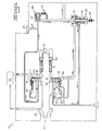
- the pumping system 10 comprises: a rotor 12; a main stage 14 of centrifugal high-speed impeller blades 16 (see FIG. 4) on one side of the rotor 12 (see FIGS. 1-3); a separate regenerative/liquid-ring starting stage 18 of liquid-ring pump blades 20 (see FIG. 5) on the rotor's opposite side (see FIGS. 1-3); and a valving means 22 that opens or closes fluid communication between the starting stage 18 and main stage 14 depending upon engine speed.
- rotor 12 is centrally mounted on rotor shaft 24.
- this shaft is driven by a drive spline (not shown) which plugs into the engine gearbox (also unshown).
- the shaft 24 is supported by angular contact bearings 26 which are oil mist lubricated.
- a standard inducer boost stage 28 At the inlet 27 of pumping system 10 is a standard inducer boost stage 28. It is fixedly mounted onto rotor shaft 24 and thus simultaneously rotates with both the main stage 14 and starting stage 18, carried on rotor 12. This inducer is attached by suitable piping to the main stage 14, with a low-pressure filter 30 in between.
- the remainder (or valving means) of pumping system 10 consists of: a Bypass Regulating and Mode Transfer Valve 32 (hereinafter "BRMTV"), which limits pressure rise in the regenerative starting stage 18 and also selects the pump's operating mode (e.g., "priming” mode, "starting” mode, or “run” mode); a check valve 34 to prevent back flow into the starting stage 18 during "run” mode in which the main stage 14 operates in lieu of starting stage 18; and a switching piston 36 which, upon receiving the appropriate signal from the BRMTV 32, strokes to either activate or deactivate the regenerative starting stage 18 by opening or closing off the starting-stage flow channel 38 (see FIG. 2).
- BRMTV Bypass Regulating and Mode Transfer Valve 32
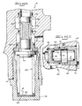
- BRMTV 32 An integral part of the present invention is BRMTV 32. Its structure is best depicted in FIG. 6. As shown therein, this valve comprises: a chamber 39 with an "upper" sleeve 40 held in position by a cover 42; a main valve body 44 that slides, relative to sleeve 40 and cover 42, within the chamber 39 to selectively open or close a start-stage window 46 or a bypass window 48; a spring 50 that rests against shims 52 inside the cover to bias the main body 44 toward its position shown in FIGS. 1, 6; and various O-rings 54, 56, 58, 60 to provide liquid-tight seals.
- FIG. 7 best illustrates the check valve 34.
- this valve Like BRMTV 32, this valve includes a main body 62 that slides inside a sleeve 64 and chamber 66.
- the sleeve is held in fixed position by a cover 68, and a spring 70, inside the cover, tends to bias the valve to its closed position shown in FIGS. 2, 7.
- Various O-rings 72, 74, 76 provide liquid-tight seals.
- the check valve 34 is connected to a reference line, with a pair of screens and a damper hole at 78.
- the damper provides dynamic stability. For similar stability, there are a pair of screens and a damper hole (at 80) associated with the BRMTV 32.
- centrifugal pumping system 10 switches from "priming” mode to "starting” mode, and to normal operation or “run” mode. Those operations are sequentially described below.
- the priming mode of pumping system 10 is shown in FIG. 1. Assuming the liquid-ring pump 18 has been previously wet, the locations of the starting stage's central inlet 81 and discharge 82 assure that sufficient fuel is always trapped within the pump 20 to produce a liquid sealing ring. This ring of liquid provides the sealing and pumping action required for vapor handling. Vapor and/or fuel-vapor mixture is drawn through the BRMTV's start-stage window 46 (see also FIG. 6) to the start-stage inlet 81 and expelled out the discharge 82 and vented overboard through a vent line 83 and bleeder plug 84 or through an automatic vent valve (not shown), until liquid is introduced at the pump inlet 81. Once this occurs, liquid fills the center of the starting stage 18, instantly allowing the liquid-ring pump to perform as a regenerative pump.
- FIG. 1 also shows the pumping system's "starting" mode. Once the regenerative/liquid-ring pump 18 is primed, it supplies fuel flow for starting until ignition has occurred and engine speed increases to a value that permits the main stage 14 to sustain pressure and flow.
- Fuel is drawn through the inducer 28, filter 30, and main stage 14 to the BRMTV 32, where it is ported through the start-stage window 46 to the start-stage inlet 81. From inlet 81, fuel flows approximately three hundred degrees around the start-stage channel 38 where, the starting stage 18, through its regenerative action, adds pressure to the flow until the pressure and flow required for engine light-off is achieved. Fuel then flows from the outlet 82 of starting stage 18, through check valve 34, and out to the fuel metering unit (not shown). As ignition occurs, and engine speed increases, the BRMTV 32 limits start-stage pressure rise by returning flow in excess of engine and actuator needs, through the bypass window 48, to the main-stage outlet 85, which is in open, fluid communication with the start-stage inlet 81.
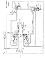
- main-stage outlet pressure eventually reaches a value roughly equivalent to the pressure that the BRMTV 32 is regulating the starting stage 18 to.
- the pressure drop across the BRMTV's bypass window 48 is eliminated, and the BRMTV 32 is no longer able to regulate start-stage outlet pressure.
- the valve 32 translates to saturate the bypass window 48 wide open (see FIG. 2).
- the start-stage window 46 in the BRMTV 32 located in the start-stage inlet line which is in fluid communication with the start-stage flow channel 38, begins to close. As this window 46 closes, a pressure drop occurs across it, causing start-stage inlet pressure to drop.
- This drop in inlet pressure is sensed by the switching piston 36 (which is biased by spring 86).
- One piston side 88 is referenced to main-stage outlet pressure, the other 89 to the flow channel 38 of the starting stage 18.
- this side 89 of the switching piston 36 sees, in effect, the average of start-stage inlet and outlet pressures.
- outlet pressure is reduced by the pressure drop through the BRMTV 32, this average pressure is also reduced.
- a pressure differential occurs across the switching piston 36, causing it to stroke (to the right, as viewed in FIGS. 1 and 2) and close off the regenerative flow channel 38.
- start-stage carbon lift seal 90 which senses main-stage outlet pressure on one side and start-stage inlet pressure on the other, lifts from the liquid-ring pump's impeller 20.
- the regenerative starting stage 18 is now inactive and no longer able to generate sufficient pressure, and the check valve 34 closes.
- the direction of flow through the BRMTV bypass window 48 reverses and all flow to the engine is supplied by the centrifugal main stage 14. This is shown by flow arrows in FIG. 2, during which the engine can be described as operating in its "run" mode.
Landscapes
- Engineering & Computer Science (AREA)
- Mechanical Engineering (AREA)
- General Engineering & Computer Science (AREA)
- Chemical & Material Sciences (AREA)
- Combustion & Propulsion (AREA)
- Structures Of Non-Positive Displacement Pumps (AREA)
Claims (5)
- Zentrifugal-Pumpsystem zum Fördern von Kraftstoff zu einem Flugzeuggasturbinentriebwerk, wobei das System versehen ist mit:einem Rotor (12) zum Antrieb durch die Turbine;einer Hauptstufenpumpe (14) mit einem Auslass (85) und einem Satz Zentrifugalläuferblätter, die auf einer Seite des Rotors (12) angeordnet sind;einer separaten regenerativen Startstufenpumpe (18) mit einem Einlass und einem Satz Läuferblätter; undeiner Ventileinrichtung (22) zum Einschalten der Startstufenpumpe (18) in einem "Startbetrieb" und zum Ausschalten der Startstufenpumpe (18) in einem "Laufbetrieb", in Abhängigkeit von der Motordrehzahl,dadurch gekennzeichnet, dass die Startstufenpumpe (18) eine Flüssigkeitsringpumpe ist, welche ihre Läuferblätter auf der anderen Seite des Rotors (12) aufweist, welche andere Seite gegenüberliegend zu der einen Seite des Rotors (12) und von derselben beabstandet ist, und
dass die Ventileinrichtung (22) in der Auslassleitung der Hauptstufenpumpe (18) ein Ventil (32) aufweist, welches die Fluidverbindung zwischen der Startstufenpumpe und der Hauptstufenpumpe (14, 18) öffnet oder schliesst, um die Kraftstoffströmung in dem "Startbetrieb" von dem Auslass (85) der Hauptstufenpumpe zu dem Einlass der Startstufenpumpe zu leiten und um die Kraftstoffströmung in dem "Laufbetrieb" von dem Auslass (85) der Hauptstufenpumpe zu dem Triebwerk unter Umgehung der Startstufenpumpe (18) umzuleiten. - Zentrifugalpumpsystem nach Anspruch 1, dadurch gekennzeichnet, dass das Ventil (32) ein Bypassregel- und Betriebsumschaltventil (32) ist, das den Druckanstieg in der regenerativen Startstufenpumpe (18) begrenzt und auch die Betriebsart des Pumpsystems wählt.
- Zentrifugalpumpsystem nach Anspruch 2, dadurch gekennzeichnet, dass die Ventileinrichtung (22) desweiteren ein Rückschlagventil (34) aufweist zum Verhindern einer Rückströmung in die Startstufenpumpe (18), im "Laufbetrieb" der Gasturbine, in welchem die Hauptstufenpumpe (14) anstelle der Startstufenpumpe (18) in Betrieb ist.
- Zentrifugalpumpsystem nach Anspruch 3, dadurch gekennzeichnet, dass die Ventileinrichtung (22) desweiteren einen Schaltkolben (36) aufweist, der auf einer Rotorwelle (24) für das Pumpsystems reitet und der, beim Empfang eines geeigneten Signals von dem Bypassregel- und Betriebsumschaltventil (32), einen Hub ausführt, um die regenerative Startstufenpumpe (18) entweder einzuschalten oder abzuschalten durch Öffnen oder Schliessen eines Strömungskanals (98) der Startstufenpumpe.
- Zentrifugalpumpsystem nach Anspruch 2, dadurch gekennzeichnet, dass das Bypassregel- und Betriebsumschaltventil (32) ein Startstufenfenster (46), ein Umgehungsfenster (48) und einen Ventilkörper (44) hat, der wahlweise beweglich ist zum Öffnen oder Schliessen des Startstufenfensters (46) oder des Umgehungsfensters (48), um die Kraftstoffströmung in dem "Startbetrieb" von dem Auslass (85) der Hauptstufenpumpe zu dem Einlass (81) der Startstufenpumpe durch das Startstufenfenster (46) zu leiten und zum Leiten der Kraftstoffströmung in dem "Laufbetrieb" von Auslass (85) der Hauptstufenpumpe durch das Umgehungsfenster (48) zu dem Triebwerk, wobei der bewegliche Ventilkörper (44) in dem "Startbetrieb" mit dem Umgehungsfenster (46) zusammenwirkt zum Begrenzen des Druckanstieges in der Startstufenpumpe während dem "Startbetrieb" durch Zurückleitung von überschüssigem Kraftstoff zu dem Auslass (85) der Hauptstufenpumpe durch das Umgehungsfenster (48).
Applications Claiming Priority (3)
| Application Number | Priority Date | Filing Date | Title |
|---|---|---|---|
| US10155493A | 1993-08-03 | 1993-08-03 | |
| US101554 | 1993-08-03 | ||
| PCT/US1994/005900 WO1995004224A1 (en) | 1993-08-03 | 1994-05-27 | Centrifugal fuel pump with starting stage |
Publications (2)
| Publication Number | Publication Date |
|---|---|
| EP0712466A1 EP0712466A1 (de) | 1996-05-22 |
| EP0712466B1 true EP0712466B1 (de) | 1997-03-19 |
Family
ID=22285260
Family Applications (1)
| Application Number | Title | Priority Date | Filing Date |
|---|---|---|---|
| EP94923883A Expired - Lifetime EP0712466B1 (de) | 1993-08-03 | 1994-05-27 | Kreiselpumpe mit auslaufstufe |
Country Status (4)
| Country | Link |
|---|---|
| US (1) | US5456574A (de) |
| EP (1) | EP0712466B1 (de) |
| DE (1) | DE69402206T2 (de) |
| WO (1) | WO1995004224A1 (de) |
Families Citing this family (21)
| Publication number | Priority date | Publication date | Assignee | Title |
|---|---|---|---|---|
| US5819524A (en) * | 1996-10-16 | 1998-10-13 | Capstone Turbine Corporation | Gaseous fuel compression and control system and method |
| US5899673A (en) * | 1996-10-16 | 1999-05-04 | Capstone Turbine Corporation | Helical flow compressor/turbine permanent magnet motor/generator |
| US6059537A (en) * | 1997-11-13 | 2000-05-09 | Sundstrand Corporation | Aircraft fuel pump with centrifugal pump and regenerative pump stages |
| US6007311A (en) * | 1997-11-14 | 1999-12-28 | Sundstrand Corporation | High speed self-lubricated fuel pump with hydrostatic bearings |
| CA2301415A1 (en) | 1999-04-19 | 2000-10-19 | Capstone Turbine Corporation | Helical flow compressor/turbine permanent magnet motor/generator |
| US6361271B1 (en) | 1999-11-19 | 2002-03-26 | Capstone Turbine Corporation | Crossing spiral compressor/pump |
| US6651441B2 (en) | 2002-01-22 | 2003-11-25 | Hamilton Sundstrand | Fluid flow system for a gas turbine engine |
| US7165932B2 (en) * | 2005-01-24 | 2007-01-23 | Visteon Global Technologies, Inc. | Fuel pump having dual single sided impeller |
| WO2007095047A2 (en) * | 2006-02-09 | 2007-08-23 | Argo-Tech Corporation | Regenerative pumping element start stage for high-speed centrifugal pump |
| DE102007013872A1 (de) * | 2007-03-20 | 2008-09-25 | Gardner Denver Deutschland Gmbh | Vakuumsystem für hohe Zusatzflüssigkeitsmengen |
| US8113804B2 (en) * | 2008-12-30 | 2012-02-14 | Hamilton Sundstrand Corporation | Vane pump with rotating cam ring and increased under vane pressure |
| US8142242B2 (en) * | 2009-05-19 | 2012-03-27 | Advanced Marine Concepts, Llc | Marine propulsion system |
| US8408233B2 (en) | 2011-03-18 | 2013-04-02 | Hamilton Sundstrand Corporation | Flow control system and method for controlling two positive displacement pumps |
| US8893466B2 (en) | 2011-03-18 | 2014-11-25 | Hamilton Sundstrand Corporation | Dual pump fuel flow system for a gas turbine engine and method of controlling |
| US10907598B2 (en) | 2018-03-07 | 2021-02-02 | Eaton Intelligent Power Limited | Self-limiting regenerative pumping element start stage for high speed centrifugal engine fuel pump and associated method |
| GB2594145B (en) * | 2020-03-04 | 2024-07-31 | Eaton Intelligent Power Ltd | Single wheel multi-stage radially-layered regenerative pump |
| EP4167892A4 (de) | 2020-06-19 | 2024-10-30 | Remedy Robotics, Inc. | Systeme und verfahren zur führung intraluminaler vorrichtungen im gefässsystem |
| CA3222522A1 (en) | 2021-07-01 | 2023-01-05 | David James Bell | Vision-based position and orientation determination for endovascular tools |
| US12121307B2 (en) | 2021-07-01 | 2024-10-22 | Remedy Robotics, Inc. | Vision-based position and orientation determination for endovascular tools |
| US11707332B2 (en) | 2021-07-01 | 2023-07-25 | Remedy Robotics, Inc. | Image space control for endovascular tools |
| DE102022001696A1 (de) * | 2022-05-13 | 2023-11-16 | Truma Gerätetechnik GmbH & Co. KG | Zweistufige Pumpe |
Family Cites Families (12)
| Publication number | Priority date | Publication date | Assignee | Title |
|---|---|---|---|---|
| GB601516A (en) * | 1944-08-30 | 1948-05-07 | Nash Engineering Co | Pumps |
| US2464144A (en) * | 1945-04-02 | 1949-03-08 | Ingersoll Rand Co | Pumping mechanism |
| US3147712A (en) * | 1960-09-02 | 1964-09-08 | Gen Motors Corp | Fuel pumping system for gas turbines |
| AU407420B2 (en) * | 1966-08-24 | 1970-10-29 | Joseph Lucas (Industries) Limited | Liquid displacement pumps |
| US3518028A (en) * | 1968-01-26 | 1970-06-30 | Trw Inc | Power reduction of liquid ring pumps |
| US3576375A (en) * | 1969-07-10 | 1971-04-27 | Bendix Corp | Fluid pumping system |
| US4347041A (en) * | 1979-07-12 | 1982-08-31 | Trw Inc. | Fuel supply apparatus |
| US4487548A (en) * | 1983-05-19 | 1984-12-11 | Chandler Evans Inc. | Centrifugal main fuel pump having starting element |
| US4864815A (en) * | 1987-12-24 | 1989-09-12 | Sundstrand Corporation | Fuel supply system with turbine driven start pump |
| US5183392A (en) * | 1989-05-19 | 1993-02-02 | Vickers, Incorporated | Combined centrifugal and undervane-type rotary hydraulic machine |
| WO1991006778A1 (en) * | 1989-11-02 | 1991-05-16 | Sundstrand Corporation | Regenerative pump and method discharging pressurized fluid therefrom |
| US5096386A (en) * | 1989-11-17 | 1992-03-17 | Sundstrand Corporation | Integral liquid ring and regenerative pump |
-
1994
- 1994-05-27 WO PCT/US1994/005900 patent/WO1995004224A1/en not_active Ceased
- 1994-05-27 DE DE69402206T patent/DE69402206T2/de not_active Expired - Fee Related
- 1994-05-27 EP EP94923883A patent/EP0712466B1/de not_active Expired - Lifetime
- 1994-12-02 US US08/349,135 patent/US5456574A/en not_active Expired - Fee Related
Also Published As
| Publication number | Publication date |
|---|---|
| DE69402206T2 (de) | 1997-10-09 |
| EP0712466A1 (de) | 1996-05-22 |
| DE69402206D1 (de) | 1997-04-24 |
| WO1995004224A1 (en) | 1995-02-09 |
| US5456574A (en) | 1995-10-10 |
Similar Documents
| Publication | Publication Date | Title |
|---|---|---|
| EP0712466B1 (de) | Kreiselpumpe mit auslaufstufe | |
| EP0298011B1 (de) | In einer Rotorkappe montiertes Schmier- und Kühlsystem | |
| US8256576B2 (en) | On-demand lubrication system for improved flow management and containment | |
| US4347041A (en) | Fuel supply apparatus | |
| US5110269A (en) | Gas turbine fuel pumping apparatus | |
| US4332527A (en) | Variable speed centrifugal pump | |
| US7007452B1 (en) | Fuel system for a gas turbine engine | |
| US4217755A (en) | Cooling air control valve | |
| US2715367A (en) | Pump and turbine for jet power unit | |
| EP3800340B1 (de) | Elektrisches pumpenunterstütztes kraftstoffsystem | |
| US3941505A (en) | Method and apparatus for pumping fuel | |
| US3576375A (en) | Fluid pumping system | |
| US6022197A (en) | Aircraft pump system with internal pressure control, comprising a regenerative pump and a centrifugal pump | |
| US5051065A (en) | Power transmission | |
| US4714405A (en) | Centrifugal pump | |
| US6059537A (en) | Aircraft fuel pump with centrifugal pump and regenerative pump stages | |
| CA1086137A (en) | Jet flap controlled fuel pump | |
| CA1080544A (en) | Pump assembly incorporating vane pump and impeller pump | |
| US3147712A (en) | Fuel pumping system for gas turbines | |
| US4643635A (en) | Vapor core centrifugal pump having main and low flow impellers | |
| US4743184A (en) | Rotary compressor with heating passage between discharge chamber and shaft seal | |
| US2782595A (en) | Fuel system for a gas turbine engine | |
| US4525129A (en) | Oil-sealed vacuum pump | |
| US4287717A (en) | Turbocharged internal combustion engine | |
| US2785634A (en) | Fluid pressurizing apparatus |
Legal Events
| Date | Code | Title | Description |
|---|---|---|---|
| PUAI | Public reference made under article 153(3) epc to a published international application that has entered the european phase |
Free format text: ORIGINAL CODE: 0009012 |
|
| 17P | Request for examination filed |
Effective date: 19960124 |
|
| AK | Designated contracting states |
Kind code of ref document: A1 Designated state(s): DE GB IT |
|
| GRAG | Despatch of communication of intention to grant |
Free format text: ORIGINAL CODE: EPIDOS AGRA |
|
| 17Q | First examination report despatched |
Effective date: 19960620 |
|
| GRAH | Despatch of communication of intention to grant a patent |
Free format text: ORIGINAL CODE: EPIDOS IGRA |
|
| GRAH | Despatch of communication of intention to grant a patent |
Free format text: ORIGINAL CODE: EPIDOS IGRA |
|
| GRAA | (expected) grant |
Free format text: ORIGINAL CODE: 0009210 |
|
| AK | Designated contracting states |
Kind code of ref document: B1 Designated state(s): DE GB IT |
|
| REF | Corresponds to: |
Ref document number: 69402206 Country of ref document: DE Date of ref document: 19970424 |
|
| PLBE | No opposition filed within time limit |
Free format text: ORIGINAL CODE: 0009261 |
|
| STAA | Information on the status of an ep patent application or granted ep patent |
Free format text: STATUS: NO OPPOSITION FILED WITHIN TIME LIMIT |
|
| 26N | No opposition filed | ||
| PGFP | Annual fee paid to national office [announced via postgrant information from national office to epo] |
Ref country code: GB Payment date: 20000419 Year of fee payment: 7 |
|
| PGFP | Annual fee paid to national office [announced via postgrant information from national office to epo] |
Ref country code: DE Payment date: 20000425 Year of fee payment: 7 |
|
| PG25 | Lapsed in a contracting state [announced via postgrant information from national office to epo] |
Ref country code: GB Free format text: LAPSE BECAUSE OF NON-PAYMENT OF DUE FEES Effective date: 20010527 |
|
| GBPC | Gb: european patent ceased through non-payment of renewal fee |
Effective date: 20010527 |
|
| PG25 | Lapsed in a contracting state [announced via postgrant information from national office to epo] |
Ref country code: DE Free format text: LAPSE BECAUSE OF NON-PAYMENT OF DUE FEES Effective date: 20020301 |
|
| PG25 | Lapsed in a contracting state [announced via postgrant information from national office to epo] |
Ref country code: IT Free format text: LAPSE BECAUSE OF NON-PAYMENT OF DUE FEES;WARNING: LAPSES OF ITALIAN PATENTS WITH EFFECTIVE DATE BEFORE 2007 MAY HAVE OCCURRED AT ANY TIME BEFORE 2007. THE CORRECT EFFECTIVE DATE MAY BE DIFFERENT FROM THE ONE RECORDED. Effective date: 20050527 |