EP0712464B1 - Piston pump - Google Patents
Piston pump Download PDFInfo
- Publication number
- EP0712464B1 EP0712464B1 EP95920733A EP95920733A EP0712464B1 EP 0712464 B1 EP0712464 B1 EP 0712464B1 EP 95920733 A EP95920733 A EP 95920733A EP 95920733 A EP95920733 A EP 95920733A EP 0712464 B1 EP0712464 B1 EP 0712464B1
- Authority
- EP
- European Patent Office
- Prior art keywords
- piston pump
- pump according
- piston
- ring
- transmission element
- Prior art date
- Legal status (The legal status is an assumption and is not a legal conclusion. Google has not performed a legal analysis and makes no representation as to the accuracy of the status listed.)
- Expired - Lifetime
Links
- 230000005540 biological transmission Effects 0.000 claims abstract description 82
- 239000000314 lubricant Substances 0.000 claims description 12
- 239000000463 material Substances 0.000 claims description 10
- 238000007789 sealing Methods 0.000 claims description 4
- 238000006073 displacement reaction Methods 0.000 claims description 2
- 230000002093 peripheral effect Effects 0.000 claims description 2
- 235000001674 Agaricus brunnescens Nutrition 0.000 claims 1
- 238000005096 rolling process Methods 0.000 claims 1
- 239000000446 fuel Substances 0.000 abstract description 13
- 230000006835 compression Effects 0.000 description 8
- 238000007906 compression Methods 0.000 description 8
- 230000004048 modification Effects 0.000 description 5
- 238000012986 modification Methods 0.000 description 5
- 229910000831 Steel Inorganic materials 0.000 description 3
- 238000002485 combustion reaction Methods 0.000 description 3
- 230000001050 lubricating effect Effects 0.000 description 3
- 239000010959 steel Substances 0.000 description 3
- 230000001133 acceleration Effects 0.000 description 2
- 239000004519 grease Substances 0.000 description 2
- 238000000034 method Methods 0.000 description 2
- 238000005299 abrasion Methods 0.000 description 1
- 238000010276 construction Methods 0.000 description 1
- 238000010438 heat treatment Methods 0.000 description 1
- 238000002347 injection Methods 0.000 description 1
- 239000007924 injection Substances 0.000 description 1
- 239000010687 lubricating oil Substances 0.000 description 1
- 238000005461 lubrication Methods 0.000 description 1
- 239000002184 metal Substances 0.000 description 1
- 230000010349 pulsation Effects 0.000 description 1
- 239000000243 solution Substances 0.000 description 1
- 239000004753 textile Substances 0.000 description 1
Images


Classifications
-
- F—MECHANICAL ENGINEERING; LIGHTING; HEATING; WEAPONS; BLASTING
- F04—POSITIVE - DISPLACEMENT MACHINES FOR LIQUIDS; PUMPS FOR LIQUIDS OR ELASTIC FLUIDS
- F04B—POSITIVE-DISPLACEMENT MACHINES FOR LIQUIDS; PUMPS
- F04B1/00—Multi-cylinder machines or pumps characterised by number or arrangement of cylinders
- F04B1/04—Multi-cylinder machines or pumps characterised by number or arrangement of cylinders having cylinders in star- or fan-arrangement
- F04B1/0404—Details or component parts
- F04B1/0426—Arrangements for pressing the pistons against the actuated cam; Arrangements for connecting the pistons to the actuated cam
-
- F—MECHANICAL ENGINEERING; LIGHTING; HEATING; WEAPONS; BLASTING
- F04—POSITIVE - DISPLACEMENT MACHINES FOR LIQUIDS; PUMPS FOR LIQUIDS OR ELASTIC FLUIDS
- F04B—POSITIVE-DISPLACEMENT MACHINES FOR LIQUIDS; PUMPS
- F04B1/00—Multi-cylinder machines or pumps characterised by number or arrangement of cylinders
- F04B1/04—Multi-cylinder machines or pumps characterised by number or arrangement of cylinders having cylinders in star- or fan-arrangement
- F04B1/0404—Details or component parts
- F04B1/0448—Sealing means, e.g. for shafts or housings
-
- F—MECHANICAL ENGINEERING; LIGHTING; HEATING; WEAPONS; BLASTING
- F04—POSITIVE - DISPLACEMENT MACHINES FOR LIQUIDS; PUMPS FOR LIQUIDS OR ELASTIC FLUIDS
- F04B—POSITIVE-DISPLACEMENT MACHINES FOR LIQUIDS; PUMPS
- F04B9/00—Piston machines or pumps characterised by the driving or driven means to or from their working members
- F04B9/02—Piston machines or pumps characterised by the driving or driven means to or from their working members the means being mechanical
- F04B9/04—Piston machines or pumps characterised by the driving or driven means to or from their working members the means being mechanical the means being cams, eccentrics or pin-and-slot mechanisms
- F04B9/045—Piston machines or pumps characterised by the driving or driven means to or from their working members the means being mechanical the means being cams, eccentrics or pin-and-slot mechanisms the means being eccentrics
Definitions
- the invention is based on a radial piston pump according to the preamble of claim 1, as is already known from DE-A1-37 01 857.
- a ring device is provided as the actuating element, which is mounted on one side of its axial extent on a ball bearing, which in turn is fixed on an eccentric at the free end of a drive shaft.
- the known ring device overlaps a support-shaped housing part, into which the pump cylinders are radially incorporated, with pump pistons emerging radially outwards, which come into contact with the ring device via cup-like designs.
- the ring device When the eccentric is driven, the ring device carries out a wobbling eccentric movement in the course of which the pump pistons are moved alternately inwards or outwards and thereby perform their suction and delivery strokes.
- the transferdoric movements between the actuating element and the pump piston are relatively small compared to known designs in which the pump pistons slide over centrally located cam tracks, but they are not completely prevented in the known embodiment.
- the pump pistons assume positions in which they are not perpendicular to the inner surface of the driving ring device.
- the known radial piston pump is provided in particular for the supply of a hydraulic anti-lock braking system, pressure medium which has more lubricating properties within limits can be selected as the conveying medium.
- pressure medium which has more lubricating properties within limits can be selected as the conveying medium.
- high sliding friction is to be expected in the contact areas between the pump pistons, which leads on the one hand to an increased power loss when driving the radial piston pump and on the other hand to increased wear. Due to material abrasion and seizure processes with high suction on the drive side of the pump pistons, a considerably limited service life can be expected here. Pumps that are exposed to petrol in this area behave as if they are lubricated and run dry.
- the radial piston pump according to the invention with the characterizing features of claim 1 has the advantage that sliding friction between the pump piston and its actuating element is completely switched off by the drive of the pump piston via a flexible transmission element. There is no sliding friction and thus loss of friction and wear are avoided.
- the pump is thus very well suited for the delivery of fuel, in particular gasoline, which is delivered under high pressure to a pressure accumulator, from where the fuel of a fuel injector is electrically controlled is supplied, via which the fuel is injected into an internal combustion engine.
- the configuration according to claim 4 results in particular in the advantage that a longitudinally symmetrical quadrilateral is formed by the transmission element and the transmission part together with the ring-shaped part that can be formed into a parallelogram without ring joints subject to sliding friction. Characterized in that the annular part is rotatably mounted on the eccentric, the intended assignment of the transmission part alignment and alignment of the annular element is maintained when the same is deflected via the eccentric.
- the configuration according to claim 6 results in a construction that is particularly simple to implement, wherein the mutually parallel parts of the transmission element can be placed in end grooves of a part receiving the pump cylinder.
- a deflection arrangement is provided on the ring-shaped part for producing the parallel course of the parts of the transmission element, which interacts with the transmission part.
- circular-cylindrical surface parts are provided on the contact areas of the parts of the transmission element, on which the two parts of the transmission element can unwind or wind up when the transmission part is displaced relative to the annular part.
- the transmission element consists of flat strip material according to claims 15 and 16, which has great flexibility in the direction of the plane of deformation with a high transmission cross section and thus resilience.
- Another advantageous embodiment According to claim 17, the storage of the annular part on the eccentric from the rest of the gasoline-filled housing is separated and sealed.
- a bellows enclosing the bearing and the end of the eccentric is provided, and a device is provided according to claim 21, by means of which lubricant can be introduced into the region of the bearing of the ring-shaped part on the eccentric, which area is encapsulated by gasoline.
- pressure lubrication can also be implemented, since the spring clamped between the outside of the bottom and the housing wall, the axial position of the annular part is secured against the inflowing lubricant pressure.
- FIG. 1 shows a longitudinal section through the radial piston pump according to the invention in a first embodiment
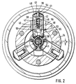
- FIG. 2 shows a section along the line II-II of FIG. 1 through the first embodiment
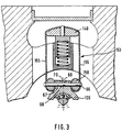
- FIG. 3 shows a partial view analogous to the section of FIG. 2 for a second embodiment
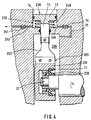
- FIG. 4 a third embodiment with a single volume 5 shows an axial view of the exemplary embodiment according to FIG. 4
- FIG. 6 shows a modified form of the sealing of the bearing on the eccentric using the exemplary embodiment according to FIG. 4, FIG.
- FIG. 7 shows a fourth exemplary embodiment with a two-part part lying along the axis of the drive shaft Transmission element
- Figure 8 shows a fifth embodiment with a part-ring-shaped part for fastening the transmission element
- Figure 9 is a section perpendicular to Figure 8 showing the drive shaft.
- the radial piston pump shown in FIG. 1 has a pump housing 1 in which a drive shaft 2 of the radial piston pump is mounted. At its one end protruding from the pump housing, a drive gear 4 is attached to the drive shaft.
- the shaft is mounted by means of two ball bearings 5, which is sealed to the outside and to an interior 6 of the radial piston pump by seals 7, so that no fuel can escape from the interior 6, which is filled with gasoline, along the drive shaft to the ball bearings.
- the drive shaft has a peg-shaped eccentric 12 which is eccentric to the central axis 11 of the drive shaft, with the eccentricity e shown in FIG.
- a roller bearing 14 is arranged, which is a needle bearing in the example shown, the z. B. has only a needle cage and a liner and axially between a shoulder 15 and a locking ring 16 with Is secured.
- annular part 20 On the needle bearing, an annular part 20 is mounted, which in the present case is pot-shaped with a bottom 21 which is in contact with the front face 17 of the eccentric 12 and there by a compression spring 22 which engages on the outside of the bottom and which is supported on a housing cover 23 the bottom inside is held on a ball 24 which is inserted into an outlet opening 18 of a lubricant channel 10 running axially through the eccentric 12.
- the lubricant channel 10 enters the drive shaft radially in the area between the two ball bearings 5 and is supplied with lubricant from a lubricant source (not shown) by a lubricant supply opening 9 which opens into the annular groove 8 arranged between the two ball bearings.
- Grease or lubricating oil that is supplied under pressure can be used as the lubricant.
- the compression spring 22 is required to hold the annular part 20 in its intended position, which is predetermined by the ball 24.
- the compression spring can be replaced by a ball, which secures the position of the ring-shaped part against axial accelerations transmitted from the internal combustion engine.
- the annular part 20 has on its side facing away from the bottom 21 a diameter widening 25 which serves to receive a shaft seal 26.
- a closed space is formed between this shaft seal and the interior of the cup-shaped annular part, which is filled with lubricant for lubricating the needle bearing 14.
- a plain bearing can also be used, which can also be used with a suitable material pairing Dry storage can be formed, then a corresponding lubricant supply and shaft seal can be dispensed with.
- the interior 6 is formed by a cup-shaped recess in the pump housing 1 and, with its cylindrical wall 28, comprises the eccentric 12 and the annular part in the circumferential direction.
- the interior space 6 is closed by the cover 23, which is also cup-shaped and encloses the housing 1 with its cylindrical wall 30 to form an annular space 31, for the tight closure of the annular space 31 to the outside with the end of its cylindrical wall in a front annular groove 32 of the pump housing 1 engages and there is a tight connection to the outer boundary ring wall of the end ring groove 32 via a seal 33 which is inserted in an outer ring groove of the cylindrical wall 30.
- Pump cylinder bores 36 are arranged in the annular web 34 of the pump housing formed between the pump interior 6 and the annular space 31, which are designed as cylindrical blind bores arranged radially to the central axis 11 and extending from the annular space 31.
- three such cylinder bores 36 are arranged at a uniform angular distance from one another. They each hold a pump piston 38, one of which protrudes axially on the end on its part projecting outward into the annular space 31 Has pin 39 on which a transmission part 40 with its bore 41 is placed.
- the transmission part is prismatic and mushroom-shaped in cross-section with a lower flat surface 42, which comes into contact with the remaining end face of the pump piston, with an upper curved surface 43 with a large radius and with a curved surface 44 adjoining this surface with a small radius.
- the transmission part is constructed symmetrically with respect to a plane passing through the pump piston axis and the central axis 11.
- a compression spring 46 is arranged within the cylinder bore 36 and is supported in an axial blind hole 47 in the pump piston 38.
- the pump piston includes a pump working space 48 in the cylinder bore, which is supplied with pressure medium, in this case gasoline, via a radial bore 49, which is controlled by the outer surface of the pump piston, during the suction stroke of the pump piston.
- pressure medium in this case gasoline
- radial bore 49 which is controlled by the outer surface of the pump piston, during the suction stroke of the pump piston.
- the radial bore is closed and the enclosed pressure medium is fed via a pressure channel 50 leading from the bottom of the cylinder bore 36, which contains a check valve 51 opening in the outflow direction, to a pressure accumulator from which, for example, fuel injection nozzles are supplied with fuel, but this is not the case here is shown in more detail.
- a flexible transmission element 53 is provided between the pump piston and the annular part 20 rotatably mounted on the eccentric.
- this consists of tape material, preferably made of steel strip, which is placed over the curved surface 43 with a large radius of the transmission element 40 and is penetrated there in the region of a form-fitting opening 54 by the pin 39 as a counterpart of a form-fitting connection.
- the transmission element is thus secured against displacement on the transmission part.
- the transmission element leads in two mutually parallel parts 55 after deflection on the curved surface 44 with a smaller radius through end-side recesses 56 of the annular web 34 to the annular part 20.
- the mutually parallel parts 55 of the transmission element 53 become cylindrical pins 58 which are axially parallel to the eccentric axis are inserted into the annular part 20, deflected and then follow the cylindrical outer surface of the annular part 20 between the two cylindrical pins 58 until they engage positively with their ends, which also have positive-locking openings 59, in a corresponding form-fitting pin inserted radially into the annular part .
- the cylindrical pins 58 have the same radius as the curved surfaces 44 of the transmission part with a small radius, the distance between the centers of curvature of this surface being the same as the distance between the axes of the cylindrical pins.
- the transfer element in the form of a ribbon forms a rectangle consisting of the two mutually parallel sides of the parts 55 of the transfer element and the imaginary connection between the centers of curvature of the curved surfaces with a small radius 44 of the transfer part and the imaginary connection between the axes of the cylinder pins 58, which imaginary connections are parallel to each other.
- the mutually parallel parts 55 are seen in the direction of rotation of the eccentric in front and behind the pump piston, what e.g. B. is also fulfilled in that they lie in a common radial plane to the axis of the drive shaft.
- the annular space 31 is hydraulically connected to the inner space 6 via the end recesses, which are provided parallel to the pump piston to the left and right of the latter.
- the interior is supplied with fuel via a fill opening 61, which can then be supplied to the pump work chamber 48 via the radial bore 49 opening into the front recess.
- the center point of the eccentric pin moves in a circle around the central axis 11 of the drive shaft and in doing so conveys the annular element 20.
- the pump piston 38 is subsequently moved inward as the eccentric continues to rotate in the direction of the arrow.
- the annular part 20 moves from its shown central position to the right, so that a parallelogram is now formed from the rectangle formed by the transmission element 53 and the transmission part 40.
- the rotational position of the annular element is maintained so that the connection between the axes of the cylinder pins 58 is still parallel to the transmission part.
- the left part 55 of the transmission element must lie somewhat on the left curved surface 44 of the transmission part and unwind from the cylinder pin 58 located underneath. Correspondingly mutually, this process takes place in the other of the parallel parts 55.
- the pump piston 38 executes its pressure stroke and delivers from there closed pump work chamber 48 the pressure medium in the pressure channel 50. Meanwhile, the pump piston adjacent in the direction of rotation executes an outward movement corresponding to its suction stroke, while the pump piston adjacent to the pump piston 38 in the opposite direction of rotation is approximately at the end of its pressure stroke.
- the actuating devices of the pump pistons consisting of the annular part 20 and the respective transmission element 53 and the transmission part 40, do not influence one another, as can easily be seen.
- the successive parts, the ring-shaped part and the eccentric 12 are accommodated within a closed space 6, which is filled with the gasoline-filled interior, so that here too the wear is kept low and a long service life of the radial piston pump when driving with gasoline as pressure medium is achieved becomes.
- the annular part 20 has no rotational movement, but only executes a circular movement around the central axis 6, it is possible that it is held in position with the aid of the compression spring against axial accelerations which are transmitted from the internal combustion engine.
- the two parallel parts 55 of the transmission element 53 are two individual tapes, which in the area of the pin 39 and the pin 60 overlap each other, each have the positive-locking opening 54 and 59 and are welded together for securing.
- Other types of connection are also possible, such as folding, screwing and the like.
- An infinity band is also advantageous, which is manufactured to the exact required length and thus has a ring shape without the overlaps shown.
- a flat ribbon made of metal is advantageous. Due to its inherent elasticity, this is not as easily deformable as a non-steel material, but the energy invested in the deformation is almost completely recovered in the course of the successive work steps. Is instead of steel z. B.
- the interior 31 or 6 of the radial piston pump is supplied with a fuel by a prefeed pump, which is approximately below 3-5 bar and by the radial piston pump z. B. is brought to pressures greater than 100 bar.
- the transmission element can also be formed from two flat strips 755 according to FIG. 7 lying parallel to one another and next to one another, with their plane pointing in the circumferential direction, both of which, on the one hand, on the annular part 720, for. B. are attached to a radially projecting rib 769 corresponding to the rib 249 of Figure 4 and on the other hand are attached to a bridge-like part 740 serving as a transfer part.
- the flat strips are guided through a corresponding recess 756 through the housing separating the interior 6 from the annular space 31. They can also be easily deformed following the deflection of the ring-shaped element and transmit the axial forces symmetrically to the pump piston.
- FIG. 3 A modification of the embodiment shown in FIGS. 1 and 2 can also be seen in FIG. 3.
- the transmission element 153 which is built from a single piece, is placed with a corresponding guide over the transmission part 140 and deflected via deflection pieces 158 on the side of the annular part 120 in such a way that two mutually parallel parts 155 in the intermediate region between the transmission part 140 and the annular part 120 arise.
- the deflecting part is again preferably cylindrical in cross section and has a central transverse bore 66 through which a transverse bolt 67 is drawn perpendicular to the plane of the band and the deflecting part 158, which through a corresponding bore 68 in a radially projecting rib 69 of the annular part 120 is guided.
- the end of the transmission element 153 is clamped between this rib and the deflection part 158 and folded onto the end face 70 of the rib 69. This results in a very good interlocking connection between the ends of the transmission element 53 and the annular part 120, the ends of this transmission element 153 for the passage of the bolt 67 being broken through twice.
- the radial piston pump according to the invention can also be designed according to FIG. 4.
- the pump piston 238 is designed as a piston which is guided in a corresponding cylinder bore 236 designed as a stepped bore.
- the larger-diameter part 72 of the stepped piston 238 serves as the actual pump piston, which, together with its smaller-diameter part 73, encloses the pump working space 248 in the larger-diameter bore 74.
- a compression spring 246 is in turn arranged in this, which moves the pump piston back during its suction stroke movement.
- a spring can also act as a tension spring on the outside of the pump piston, as shown in FIG. 5.
- the pump working chamber 248 is in turn supplied with fuel via a suction line 75 which, if control by the pump piston itself is no longer present, now contains a filling check valve 76.
- the compressed fuel is delivered to the storage, not shown.
- the stepped piston part 73 which has a smaller diameter and projects into the interior 206 on the side facing away from the pump working space 248, is connected there to a transmission element 253 which is modified compared to the above exemplary embodiments.
- This consists of a sheet-shaped part which is connected on the one hand at the end of the stepped piston part 73, which is smaller in diameter, and at the other end is connected to a rib 269 which projects radially from the annular part 220 in the axial direction.
- the annular part 220 is now supported by a ball bearing 77 on the eccentric 12, which bearing can absorb both radial and axial forces, so that no axial securing of the annular part 22 is required. Otherwise, however, this is carried out in the same way as the ring-shaped part 20 from FIG. 1 in such a way that it is cup-shaped with a lip seal 226 that closes off the interior of the cup-shaped part.
- Figure 5 shows a modification of Figure 4, the axial plan view of this embodiment, from which it can be seen that the leaf-shaped transmission element 253 can deform according to the offset e of the eccentric 12.
- the pump piston is shown schematically there by a tension spring 78, which is suspended from the housing, acted radially outwards.
- the transmission element 253 ′ can also be fastened to the peripheral surface of the annular part 220 instead of to a rib 269, as shown in FIG. 5.
- FIG. 6 finally shows a modified form of the exemplary embodiment according to FIG. 4, in which the annular element 320 has only an annular shape with radially projecting ribs 369 to which the leaf-shaped transmission elements 253 already known from FIG. 4 are fastened for actuating the stepped piston 238 Sealing the bearing point of the annular element 320 is now clamped between the ball bearing 77 of Figure 4 and the annular element 320, a bellows 79, which is bag-shaped and with its outer ends via flanges 81 tight with the end wall of the pump housing surrounding the exit of the drive shaft 2 connected is.
- this solution has the disadvantage that mass balancing, as is provided in the exemplary embodiment according to FIG. 1, cannot be used.
- a weight compensation is provided, in the form of a mass part 86 as a balancing mass, which initially as a radially extending part 87 projecting from the drive shaft 2 and then as axially parallel, the ring-shaped element 20 overlapping part 88 is executed and is arranged diametrically the eccentricity of the eccentric.
- the mass sitting on the eccentric can be reduced by using a plain bearing instead of a roller bearing, which at the same time also has dry running properties in such a way that it can be flushed with petrol, the mass of the annular part can also be Omission of the shaft seal 26 can be significantly reduced and such a mass balance is eliminated.
- FIG. 8 shows a fifth exemplary embodiment as a section perpendicular to the view of the drive shaft 802 of this exemplary embodiment shown in FIG. 9.
- This embodiment is suitable for a series arrangement of several pump pistons, for which purpose the drive shaft 802 is supported on both sides with eccentrics 812 arranged between them. These are either separated from one another by bearings 90, as shown on the left half of FIG. 9, or by intermediate disks 89, as shown in FIG the right half.
- Bearing shells 820 are mounted on the eccentrics 812 by means of semi-cylindrical bearing surfaces 887, each of which forms a bearing surface 888 for a transmission element 853 with its rounded outer surface opposite the bearing surface. This is subsequently constructed in the same way as the transmission element 53 from FIG. 2.
- the transmission element 853 can be designed as a continuous band or joined together at one point, the outer contour of the bearing shell 820 at the position area of the transmission element being designed analogously to the outer contour of the transmission part 840.
- the compression spring 46 ensures that the transmission element 853 is always tensioned and the bearing shell 820 with its open bearing surface is constantly held on the eccentric 812 so that it can carry out the required drive on the pump piston by adjusting the eccentric.
- the pump work chamber 48 which is enclosed by the pump piston in the housing part lying between the recesses 856, is in turn supplied with fuel by a filling check valve 876 and a suction line 875, which is then brought to high pressure via the check valve 851 and the pressure channel 850.
- the check valves are accommodated in blind bores in the housing, which blind bores are closed by plugs 190.
- the bearing shells 820 are guided axially, either between the housing wall and an intermediate bearing 90 or between two intermediate bearings in the central region of the drive shaft 802 or by means of intermediate disks 89 or, respectively, provided on the drive shaft 802 between the eccentrics 820 Housing wall.
- This arrangement also results in a very compact unit with low moving masses due to the semi-annular bearing shells.
- the embodiments of the piston pump according to the invention described here can also be used as a hydraulic drive machine in that, in a kinematic reversal, pressure medium from a high-pressure source is fed to the pump work chamber in a controlled manner until the pump piston, now serving as a working piston, has carried out its working stroke, which it has via the eccentric 12 the shaft 2, which is now an output shaft in the sense of a crankshaft, transmits via the transmission elements 53, 55 and drives them out and via this at the same time another pump piston for its return stroke.
- the pressure medium supply to the work space is interrupted and a relief line to a relief space is opened, so that the pump piston, through one or more other of the pump pistons, can move its return stroke over the eccentric and the transmission element, doing the one present in the work space Pump pressure quantity in the open relief line promotes.
Landscapes
- Engineering & Computer Science (AREA)
- Mechanical Engineering (AREA)
- General Engineering & Computer Science (AREA)
- Reciprocating Pumps (AREA)
- Fuel-Injection Apparatus (AREA)
- Lubrication Of Internal Combustion Engines (AREA)
Abstract
Description
Die Erfindung geht von einer Radialkolbenpumpe nach der Gattung des Patentanspruchs 1 aus, wie sie bereits aus der DE-A1-37 01 857 bekannt ist. Dort ist als Betätigungselement eine Ringvorrichtung vorgesehen, die auf der einen Seite ihrer axialen Erstreckung auf einem Kugellager gelagert ist, das seinerseits auf einem Exzenter am freien Ende einer Antriebswelle fixiert ist. Die bekannte Ringvorrichtung übergreift dabei einen stützenförmigen Gehäuseteil, in den radial die Pumpenzylinder eingearbeitet sind mit radial nach auswärts austretenden Pumpenkolben, die dort über topfartige Ausbildungen an der Ringvorrichtung zur Anlage kommen. Bei angetriebenem Exzenter führt die Ringvorrichtung eine taumelnde Extenterbewegung durch, im Laufe der die Pumpenkolben wechselweise nach innen oder nach außen bewegt werden und dabei ihre Saug- und Förderhübe ausführen. Bei dieser Ausgestaltung einer Radialkolbenpumpe sind zwar gegenüber bekannten Ausführungen, bei denen die Pumpenkolben über zentrisch liegende Nockenbahnen gleiten, die transferdorischen Bewegungen zwischen dem Betätigungselement und dem Pumpenkolben relativ gering, doch sind diese bei der bekannten Ausgestaltung auch nicht völlig unterbunden. Insbesondere nehmen die Pumpenkolben je nach Drehstellung der Ringvorrichtung Lagen ein, in denen sie nicht senkrecht zur Innenoberfläche der antreibenden Ringvorrichtung liegen. Damit ergeben sich dennoch Querkräfte an der Berührungsstelle der Pumpenkolben mit der Ringvorrichtung und gleitende Reibungen, da konstruktionsbedingt sich die Oberfläche der Ringvorrichtung im Verhältnis zu den Pumpenkolben verschiebt. Die bekannte Radialkolbenpumpe ist insbesondere für die Versorgung einer hydraulischen Antiblockieranlage vorgesehen, wobei als Fördermedium Druckmittel gewählt werden kann, das in Grenzen mehr Schmiereigenschaften aufweist. Soll eine solche Pumpe jedoch zur Druckerzeugung von Medien dienen, die nur geringe bis keine Schmiereigenschaften haben, wie z. B. Benzin, so ist in den Kontaktbereichen zwischen den Pumpenkolben mit einer hohen Gleitreibung zu rechnen, die zum einen zu einer erhöhten Verlustleistung beim Antrieb der Radialkolbenpumpe führt und zum anderen zu erhöhtem Verschleiß. Aufgrund von Materialabtragungen und Freßvorgängen bei hohem Sog an der Antriebsseite der Pumpenkolben ist hier mit einer erheblich eingeschränkten Lebensdauer zu rechnen. Pumpen, die in diesem Bereich Benzin ausgesetzt sind, verhalten sich so, als ob sie geschmiert im Trockenlauf betrieben werden.The invention is based on a radial piston pump according to the preamble of
Die erfindungsgemäße Radialkolbenpumpe mit den kennzeichnenden Merkmalen des Patentanspruchs 1 hat demgegenüber den Vorteil, daß durch den Antrieb des Pumpenkolbens jeweils über ein biegsames Übertragungselement eine Gleitreibung zwischen dem Pumpenkolben und seinem Betätigungselement völlig ausgeschaltet wird. Es tritt keine Gleitreibung auf, und somit werden Reibleistungsverluste und Verschleiß vermieden. Somit wird die Pumpe sehr gut geeignet für die Förderung von Kraftstoff, insbesondere Benzin, der unter hohem Druck in einen Druckspeicher gefördert wird, von wo elektrisch gesteuert der Kraftstoff einer Kraftstoffeinspritzdüse zugeführt wird, über die der Kraftstoff an einer Brennkraftmaschine eingespritzt wird.The radial piston pump according to the invention with the characterizing features of
Durch die Ausgestaltung gemäß Patentanspruch 4 ergibt sich insbesondere der Vorteil, daß durch das Übertragungselement und das Übertragungsteil zusammen mit dem ringförmigen Teil ein längs-symmetrisches Viereck gebildet wird, daß sich zu einem Parallelogramm formen läßt, ohne daß gleitreibungbehaftete Ringgelenke vorhanden sind. Dadurch, daß das ringförmige Teil auf dem Exzenter drehbar gelagert ist, bleibt die zueinander vorgesehene Zuordnung von Übertragungsteilausrichtung und Ausrichtung des ringförmigen Elements bei einer Auslenkung desselben über den Exzenter erhalten. Durch die Ausgestaltung nach Anspruch 6 ergibt sich dabei eine besonders einfach zu verwirklichende Konstruktion, wobei die zueinander parallel verlaufenden Teile des übertragungselements in stirnseitigen Nuten eines den Pumpenzylinder aufnehmenden Teils gelegt werden können. In besonders vorteilhafter Weise wird gemäß Patentanspruch 8 zur Erzeugung des parallelen Verlaufes der Teile des übertragungselements eine Umlenkanordnung am ringfömigen Teil vorgesehen, die mit dem Übertragungsteil zusammenwirkt. Dabei sind gemäß Patentanspruch 13 an den Anlagebereichen der Teile des Übertragungselements kreiszylindrisch verlaufende Oberflächenteile vorgesehen, an denen bei einer Verschiebung des Übertragungsteils relativ zum ringförmigen Teil die beiden Teile des Übertragungselements sich ab- bzw. aufwickeln können. Vorteilhaft besteht das Übertragungselement aus Flachbandmaterial gemäß Patentansprüche 15 und 16, welches eine große Flexibilität in Richtung der Verformungsebene aufweist bei hohem Übertragungsquerschnitt und damit Beanspruchbarkeit. Weiterhin vorteilhafte Ausführung gemäß Patentanspruch 17 ist die Lagerung des ringförmigen Teils auf dem Exzenter vom übrigen, benzingefüllten Gehäuse abgetrennt und abgedichtet. Damit werden gute Lagerungsverhältnisse erreicht unter Vermeidung eines durch Einwirkung des Benzins möglichen Trockenlauf, wie eingangs erwähnt. In Abwandlung dazu ist gemäß Patentanspruch 19 ein das Lager und das Ende des Exzenters einschließender Balg vorgesehen und gemäß Patentanspruch 21 eine Einrichtung bereitgestellt, durch die Schmiermittel in den vom Benzin gefüllten Innenraum abgekapselten Bereich des Lagers des ringförmigen Teils auf dem Exzenter eingebracht werden kann. Gemäß Patentanspruch 13 kann dabei auch eine Druckmittelschmierung verwirklicht werden, da durch die zwischen Außenseite des Bodens und der Gehäusewand eingespannten Feder die axiale Lage des ringförmigen Teils gesichert ist gegen den einströmenden Schmiermitteldruck.The configuration according to claim 4 results in particular in the advantage that a longitudinally symmetrical quadrilateral is formed by the transmission element and the transmission part together with the ring-shaped part that can be formed into a parallelogram without ring joints subject to sliding friction. Characterized in that the annular part is rotatably mounted on the eccentric, the intended assignment of the transmission part alignment and alignment of the annular element is maintained when the same is deflected via the eccentric. The configuration according to claim 6 results in a construction that is particularly simple to implement, wherein the mutually parallel parts of the transmission element can be placed in end grooves of a part receiving the pump cylinder. In a particularly advantageous manner, a deflection arrangement is provided on the ring-shaped part for producing the parallel course of the parts of the transmission element, which interacts with the transmission part. In this case, according to claim 13, circular-cylindrical surface parts are provided on the contact areas of the parts of the transmission element, on which the two parts of the transmission element can unwind or wind up when the transmission part is displaced relative to the annular part. Advantageously, the transmission element consists of flat strip material according to
Weitere Vorteile der in den Unteransprüchen aufgeführten Ausgestaltungen der Erfindung sind der nachfolgenden Beschreibung zu entnehmen.Further advantages of the embodiments of the invention listed in the subclaims can be found in the description below.
Vier Ausführungsbeispiele der Erfindung sind in der Zeichnung dargestellt und werden in der nachfolgenden Beschreibung näher erläutert. Es zeigen Figur 1 einen Längsschnitt durch die erfindungsgemäße Radialkolbenpumpe in einem ersten Ausführungsbeispiel, Figur 2 einen Schnitt gemäß der Linie II-II von Figur 1 durch das erste Ausführungsbeispiel, Figur 3 eine Teilansicht analog dem Schnitt von Figur 2 für ein zweites Ausführungsbeispiel, Figur 4 ein drittes Ausführungsbeispiel mit einem Einzelband als Übertragungselement pro Pumpenkolben, Figur 5 eine Axialsicht auf das Ausführungsbeispiel nach Figur 4, Figur 6 eine abgewandelte Form der Abdichtung des Lagers auf dem Exzenter anhand des Ausführungsbeispiels nach Figur 4, Figur 7 ein viertes Ausführungsbeispiel mit in einem längs zur Achse der Antriebswelle liegenden zweiteiligen Übertragungselement, Figur 8 ein fünftes Ausführungsbeispiel mit einem teilringförmigen Teil zur Befestigung des Übertragungselements und Figur 9 einen Schnitt senkrecht zu Figur 8 mit Darstellung der Antriebswelle.Four embodiments of the invention are shown in the drawing and are explained in more detail in the following description. 1 shows a longitudinal section through the radial piston pump according to the invention in a first embodiment, FIG. 2 shows a section along the line II-II of FIG. 1 through the first embodiment, FIG. 3 shows a partial view analogous to the section of FIG. 2 for a second embodiment, FIG. 4 a third embodiment with a
Die in Figur 1 wiedergegebene Radialkolbenpumpe weist ein Pumpengehäuse 1 auf, in der eine Antriebswelle 2 der Radialkolbenpumpe gelagert ist. An ihrem einen aus dem Pumpengehäuse herausragenden Ende ist auf der Antriebswelle ein Antriebszahnrad 4 befestigt. Die Welle ist mittels zweier Kugellager 5 gelagert, die nach außen und zu einem Innenraum 6 der Radialkolbenpumpe durch Dichtungen 7 abgedichtet ist, so daß aus dem Innenraum 6, der mit Benzin gefüllt ist, kein Kraftstoff entlang der Antriebswelle zu den Kugellagern austreten kann.The radial piston pump shown in FIG. 1 has a
An ihrem in den Innenraum 6 hereinragenden Ende weist die Antriebswelle einen zapfenförmigen zur Mittelachse 11 der Antriebswelle exzentrischen Exzenter 12 auf mit der der Figur 2 entnehmbaren Exzentrizität e. Auf dem Exzenter ist ein Wälzlager 14 angeordnet, das im ausgeführten Beispiel ein Nadellager ist, das aus Platzgründen z. B. nur einen Nadelkäfig und eine Laufbüchse aufweist und axial zwischen einer Schulter 15 und einem Sicherungsring 16 mit Gleitscheibe gesichert ist. Auf dem Nadellager ist ein ringförmiges Teil 20 gelagert, das im vorliegenden topfförmig ausgebildet ist mit einem Boden 21, der gegenüber der Stirnseite 17 des Exzenters 12 und dort durch eine außen am Boden angreifende Druckfeder 22, die sich an einem Gehäusedeckel 23 abstützt in Anlage mit der Bodeninnenseite an einer Kugel 24 gehalten ist, die in eine Austrittsöffnung 18 eines axial durch den Exzenter 12 verlaufenden Schmiermittelkanals 10 eingesetzt ist. Der Schmiermittelkanal 10 tritt radial im Bereich zwischen den beiden Kugellagern 5 in die Antriebswelle ein und wird von einer Schmiermittelzuführöffnung 9, die in die zwischen den beiden Kugellagern angeordneten Ringnut 8 mündet, aus einer nicht weiter gezeigten Schmiermittelquelle mit Schmiermittel versorgt. Als Schmiermittel kann Fett oder Schmieröl, das unter Druck zugeführt wird, verwendet werden. Insbesondere in letzterem Fall ist die Druckfeder 22 erforderlich, um das ringförmige Teil 20 in seiner vorgesehenen Position, die durch die Kugel 24 vorgegeben ist, zu halten. Bei einer Schmierung mit Fett treten keine nennenswerten axialen Kräfte auf. In diesem Fall kann die Druckfeder durch eine Kugel ersetzt werden, die die Position des ringförmigen Teils gegen von der Brennkraftmaschine her übertragene Axialbeschleunigungen sichert.At its end protruding into the
Das ringförmige Teil 20 weist an seiner dem Boden 21 abgewanden Seite eine Durchmessererweiterung 25 auf, die zur Aufnahme einer Wellendichtung 26 dient. Somit wird zwischen dieser Wellendichtung und dem Innern des topfförmig ausgebildeten ringförmigen Teils ein geschlossener Raum gebildet, der mit Schmiermittel zur Schmierung des Nadellagers 14 gefüllt ist. Statt eines Nadellagers ist auch ein Gleitlager verwendbar, das bei geeigneter Materialpaarung auch als Trockenlager ausgebildet werden kann, dann kann auf eine entsprechende Schmiermittelzufuhr und Wellendichtung verzichtet werden.The annular part 20 has on its side facing away from the bottom 21 a diameter widening 25 which serves to receive a shaft seal 26. Thus, a closed space is formed between this shaft seal and the interior of the cup-shaped annular part, which is filled with lubricant for lubricating the needle bearing 14. Instead of a needle bearing, a plain bearing can also be used, which can also be used with a suitable material pairing Dry storage can be formed, then a corresponding lubricant supply and shaft seal can be dispensed with.
Der Innenraum 6 wird durch eine topfförmige Ausnehmung im Pumpengehäuse 1 gebildet und umfaßt mit seiner zylindrischen Wand 28 den Exzenter 12 und das ringförmige Teil in Umfangsrichtung. Stirnseitig ist der Innenraum 6 durch den Deckel 23 verschlossen, der ebenfalls tassenförmig ausgebildet ist und mit seiner zylindrischen Wand 30 unter Bildung eines Ringraumes 31 das Gehäuse 1 umschließt, zum dichten Verschluß des Ringraumes 31 nach außen mit dem Ende seiner zylindrischen Wand in eine Stirnringnut 32 des Pumpengehäuses 1 eingreift und dort über eine Dichtung 33, die in einer Außenringnut der zylindrischen Wand 30 eingelegt ist, eine dichte Verbindung zur äußeren Begrenzungsringwand der Stirnringnut 32 eingeht. Da beim Betrieb der Radialkolbenpumpe in dem Ringraum 33 ein höherer Druck als der atmosphärische Umgebungsdruck herrscht, unterstützt die Druckdifferenz zwischen Ringraum 31 und Umgebung die dichte Anlage der zylindrischen Wand 30 mit der Dichtung 33 an der zylindrischen Wand der Ringnut 32.The
In dem zwischen den Pumpeninnenraum 6 und dem Ringraum 31 gebildeten Ringsteg 34 des Pumpengehäuses sind Pumpenzylinderbohrungen 36 angeordnet, die als vom Ringraum 31 ausgehende radial zur Mittelachse 11 angeordnete zylindrische Sackbohrungen ausgeführt sind. Im ausgeführten Beispiel sind drei solche Zylinderbohrungen 36 im gleichmäßigen Winkelabstand zueinander angeordnet. Sie nehmen jeweils einen Pumpenkolben 38 auf, der auf seinem nach außen in den Ringraum 31 ragenden Teil stirnseitig in axialer Verlängerung einen Zapfen 39 aufweist, auf den ein Übertragungsteil 40 mit seiner Bohrung 41 aufgesetzt ist. Der Übertragungsteil ist prismatisch ausgebildet und im Querschnitt pilzförmig mit einer unteren Planfläche 42, die in Anlage an der verbleibenden Stirnseite des Pumpenkolbens kommt, mit einer oberen gewölbten Fläche 43 mit großem Radius und mit einer gewölbten sich an diese Fläche anschließenden Fläche 44 mit kleinem Radius. In bezug auf eine durch die Pumpenkolbenachse und die Mittelachse 11 gehende Ebene ist das Übertragungsteil symmetrisch aufgebaut.
Innerhalb der Zylinderbohrung 36 ist eine Druckfeder 46 angeordnet, die sich in einem axialen Sackloch 47 im Pumpenkolben 38 abstützt. Der Pumpenkolben schließt in der Zylinderbohrung einen Pumpenarbeitsraum 48 ein, der über eine Radialbohrung 49, die von der Mantelfläche des Pumpenkolbens gesteuert wird, beim Saughub des Pumpenkolbens mit Druckmittel, in diesem Falle Benzin, versorgt wird. Beim Druckhub des Pumpenkolbens wird die Radialbohrung verschlossen und das eingeschlossene Druckmittel über einen vom Boden der Zylinderbohrung 36 abführenden Druckkanal 50, der ein in Ausflußrichtung öffnendes Rückschlagventil 51 enthält, einem Druckspeicher zugeführt, aus dem beispielsweise Kraftstoffeinspritzdüsen mit Kraftstoff versorgt werden, der aber im vorliegenden nicht näher dargestellt ist.A
Der Pumpenkolben wird von dem Exzenter 12 angetrieben. Dazu ist zwischen dem Pumpenkolben und dem auf dem Exzenter drehbar gelagerten ringförmigen Teil 20 ein biegsames Übertragungselement 53 vorgesehen. Dieses besteht im ausgeführten Beispiel nach Figuren 1 und 2 aus Bandmaterial, vorzugsweise aus Stahlband, das über die gewölbte Fläche 43 mit großem Radius des Übertragungselements 40 gelegt ist und dort im Bereich einer Formschlußöffnung 54 vom Zapfen 39 als Pendant einer Formschlußverbindung durchdrungen ist. Damit ist das Übertragungselement gegen Verschieben auf dem Übertragungsteil gesichert. Das Übertragungselement führt in zwei zueinander parallelen Teilen 55 nach Umlenkung an der gewölbten Fläche 44 mit kleinerem Radius durch stirnseitige Ausnehmungen 56 des Ringstegs 34 hindurch zum ringförmigen Teil 20. Dort werden die zueinander parallelen Teile 55 des Übertragungselements 53 an Zylinderstifte 58, die achsparallel zur Exzenterachse in das ringförmige Teil 20 eingesetzt sind, umgelenkt und folgen dann der zylindrischen Außenfläche des ringförmigen Teils 20 zwischen den beiden Zylinderstiften 58, bis sie mit ihren Enden, die ebenfalls Formschlußöffnungen 59 aufweisen, formschlüssig in einen entsprechenden, radial in das ringförmige Teil eingesetzten Formschlußzapfen eingreifen. Die Zylinderstifte 58 haben dabei denselben Radius wie die gewölbten Flächen 44 des Übertragungsteils mit kleinem Radius, wobei der Abstand der Krümmungsmittelpunkte dieser Fläche gleich groß ist wie der Abstand der Achsen der Zylinderstife voneinander. Auf diese Art und Weise wird durch das so umgelegte Übertragungselement in Form von Flachband ein Rechteck gebildet bestehend aus den beiden zueinander parallelen Seiten der Teile 55 des Übertragungselements und der gedachten Verbindung zwischen den Krümmungsmittelpunkten der gewölbten Flächen mit kleinem Radius 44 des Übertragungsteils und der gedachten Verbindung zwischen den Achsen der Zylinderstifte 58, welche gedachten Verbindungen zueinander parallel liegen. Die zueinander parallel verlaufenden Teile 55 liegen dabei in Drehrichtung des Exzenters gesehen vor und hinter dem Pumpenkolben, was z. B. auch dadurch erfüllt ist, daß sie in einer gemeinsamen, zur Achse der Antriebswelle radialen Ebene liegen.The pump piston is driven by the eccentric 12. For this purpose, a
Über die stirnseitigen Ausnehmungen, die parallel zum Pumpenkolben links und rechts von diesem vorgesehen sind, ist der Ringraum 31 mit dem Innenraum 6 hydraulisch verbunden. Der Innenraum wird über eine Füllöffnung 61 mit Kraftstoff versorgt, der dann über die in die stirnseitige Ausnehmung mündende Radialbohrung 49 dem Pumpenarbeitsraum 48 zugeführt werden kann.The
Im Betrieb bewegt sich der Mittelpunkt des Exzenterzapfens kreisförmig um die Mittelachse 11 der Antriebswelle und befördert dabei das ringförmige Element 20. Ausgehend von der Position des einen Pumpenkolbens 38 in Figur 2, bei dem sich die Achse 62 des Exzenters in bezug auf den oberen Pumpenkolben 38 und die Förderung unteren Totpunktstellung befindet, wird bei Weiterdrehung des Exzenters in Pfeilrichtung der Pumpenkolben 38 in der Folge nach innen bewegt. Dabei bewegt sich das ringförmige Teil 20 aus seiner gezeigten Mittelstellung nach rechts, so daß aus dem vom Übertragungselement 53 und dem Übertragungsteil 40 gebildeten Rechteck jetzt ein Parallelogramm entsteht. Die Drehlage des ringförmigen Elements wird dabei beibehalten, so daß die Verbindung zwischen den Achsen der Zylinderstifte 58 weiterhin parallel zu dem Übertragungsteil liegt. Dabei muß sich der linke Teil 55 des Übertragungselements etwas auf die linke gewölbte Oberfläche 44 des Übertragungsteils auflegen und von dem darunter liegenden Zylinderstift 58 abwickeln. Entsprechend gegenseitig erfolgt dieser Vorgang bei dem anderen der parallelen Teile 55. In der Folge führt der Pumpenkolben 38 seinen Druckhub aus und fördert aus dem nun verschlossenen Pumpenarbeitsraum 48 das Druckmittel in den Druckkanal 50. Währenddessen führt der in Drehrichtung benachbarte Pumpenkolben eine Auswärtsbewegung entsprechend seinem Saughub aus, während der dem Pumpenkolben 38 entgegen Drehrichtung benachbarte Pumpenkolben in etwa am Ende seines Druckhubs ist. Die Betätigungseinrichtungen der Pumpenkolben bestehend aus dem ringförmigen Teil 20 und dem jeweiligen Übertragungselement 53 und dem Übertragungsteil 40 beeinflussen, wie leicht ersichtlich, einander nicht. Auf diese Art und Weise werden die Bewegungen des Exzenters ohne Gleitreibung und Reibverluste auf die Pumpenkolben übertragen. Die gleich großen Radien, auf denen die parallelen Teile sich abwickeln bzw. aufwickeln, garantieren eine exakte Parallelführung ohne relative Schiebebewegung zueinander und mit sehr geringen Realpressungen. Das ringförmige Element führt dabei in bezug auf die Achse 62 des Exzenters keine Drehbewegung aus, vielmehr bewegt sich der Exzenter selbst unter dem ringförmigen Teil. Durch die Auslenkung der zueinander parallelen Teile 55 von der Rechteckform zum Parallelogramm ergibt sich ein sanfterer Anlauf des jeweiligen Pumpenkolbenförderhubes, was vorteilhaft ist für die Minderung von Druckpulsationen und die Minderung von Geräuschentwicklung. Diese besondere Betätigungseinrichtung der Pumpenkolben erlaubt es, von Benzin umgeben mit geringstmöglichem Verschleiß die Radialkolbenpumpe zu betreiben. Dagegen sind die aufeinander ablaufenden Teile, der ringförmige Teil und der Exzenter 12 innerhalb eines geschlossenen, von dem Benzin gefüllten Innenraum 6 getrennten Raumes untergebracht, so daß auch hier der Verschleiß niedrig gehalten ist und eine hohe Lebensdauer der Radialkolbenpumpe bei Trieb mit Benzin als Druckmittel erreicht wird. Dadurch, daß der ringförmige Teil 20 keine Drehbewegung, sondern nur eine Kreisbewegung rund um die Mittelachse 6 ausführt, ist es möglich, daß er mit Hilfe der Druckfeder gegen Axial-Beschleunigungen, die von der Brennkraftmaschine her übertragen werden, in Position gehalten wird.In operation, the center point of the eccentric pin moves in a circle around the central axis 11 of the drive shaft and in doing so conveys the annular element 20. Starting from the position of the one
Im vorstehenden sind die beiden parallelen Teile 55 des Übertragungselements 53 zwei Einzelbänder, die im Bereich des Zapfens 39 bzw. des Zapfens 60 einander überlappend jeweils die Formschlußöffnung 54 bzw. 59 aufweisen und zur Sicherung miteinander verschweißt sind. Es sind auch andere Verbindungsarten möglich, wie Falzung, Verschraubung und ähnliches. Vorteilhaft ist auch ein Unendlichband, das auf die exakte, erforderliche Länge gefertigt wird und also Ringform hat ohne die gezeigten Überlappungen. Bei der Materialauswahl für das Übertragungselement ist ein Flachband aus Metall vorteilhaft. Dieses ist wegen der Eigenelastizität zwar nicht so leicht verformbar wie ein Nichtstahlmaterial, doch wird die für die Verformung investierte Energie im Laufe der aufeinander abfolgenden Arbeitsgänge nahezu restlos wieder zurückgewonnen. Wird statt Stahl z. B. ein Übertragungselement aus Textilband verwendet, so muß mit einem Leistungsverlust durch innere Erwärmung des Materials bei seiner Verformung gerechnet werden. Dank Flachbandmaterial ist es auch ohne weiteres denkbar, andere Querschnittsformen des Übertragungselements zu verwenden, wenn auch Flachband im vorliegenden wegen der geometrischen Führung und seiner hohen Flexibilität in Umfangsrichtung zum ringförmigen Teil Vorteile aufweist. Der Innenraum 31 bzw. 6 der Radialkolbenpumpe wird im Betrieb von einer Vorförderpumpe mit einem Kraftstoff versorgt, der ca. unter 3 - 5 bar steht und durch die Radialkolbenpumpe z. B. auf Drucke größer 100 bar gebracht wird.In the foregoing, the two
In Abwandlung der in den Figuren 1 und 2 gezeigten Ausführungsform kann das Übertragungselement auch aus zwei parallel zueinander und nebeneinander liegenden, mit ihrer Ebene in Umfangsrichtung weisenden Flachbänder 755 gemäß Figur 7 gebildet sein, die beide einerseits an dem ringförmigen Teil 720 z. B. an einer radial abstehenden Rippe 769 entsprechend der Rippe 249 von Figur 4 befestigt sind und andererseits an einem brückenartig ausgebildeten, als Übertragsteil dienenden Teil 740 befestigt sind. Dieses greift an dem zwischen den Flachbändern liegenden Pumpenkolben 738 an. Die Flachbänder sind dabei durch entsprechende Ausnehmung 756 durch das den Innenraum 6 vom Ringraum 31 trennende Gehäuse geführt. Auch sie können der Auslenkung des ringförmigen Elements folgend leicht verformt werden und übertragen die axialen Kräfte symmetrisch auf den Pumpenkolben.In a modification of the embodiment shown in FIGS. 1 and 2, the transmission element can also be formed from two
Eine Abwandlung der in den Figuren 1 und 2 gezeigten Ausführungsform ist ferner der Figur 3 zu entnehmen. Dort ist das aus einem einzigen Stück gebaute Übertragungselement 153 mit einer entsprechenden Führung über das Übertragungsteil 140 gelegt und über Umlenkstücke 158 auf der Seite des ringförmigen Teils 120 umgelenkt derart, daß wiederum zwei zueinander parallele Teile 155 im Zwischenbereich zwischen dem Übertragungsteil 140 und dem ringförmigen Teil 120 entstehen. Das Umlenkteil ist hierbei wiederum vorzugsweise zylindrisch im Querschnitt und weist eine mittige Querbohrung 66 auf, durch die senkrecht zur Bandebene und dem Umlenkteil 158 ein Querbolzen 67 gezogen ist, der durch eine entsprechende Bohrung 68 in einer radial vorstehenden Rippe 69 des ringförmigen Teils 120 geführt ist. Zwischen dieser Rippe und dem Umlenkteil 158 ist das Ende des Übertragungselement 153 jeweils eingespannt und auf die Stirnseite 70 der Rippe 69 umgelegt. Somit ergibt sich eine sehr gute formschlüssige Verbindung zwischen den Enden des Übertragungselements 53 und dem ringförmigen Teil 120, wobei die Enden dieses Übertragungselements 153 der Durchführung des Bolzens 67 zweimal durchbrochen sind.A modification of the embodiment shown in FIGS. 1 and 2 can also be seen in FIG. 3. There, the
Im vorstehenden wurde zwischen Anlenkung am Pumpenkolben und Anlenkung am ringförmigen Teil ein möglichst großer Abstand gewählt, womit erreicht wurde, daß das Übertragungselement 53 bzw. 153 nicht sehr stark verformt wird. Will man eine größere Verformung erlauben, so läßt sich die erfindungsgemäße Radialkolbenpumpe auch gemäß Figur 4 ausführen. In diesem Falle ist der Pumpenkolben 238 als Kolben ausgeführt, der in einer entsprechenden als Stufenbohrung ausgeführten Zylinderbohrung 236 geführt ist. Dabei dient der im Durchmesser größere Teil 72 des Stufenkolbens 238 als eigentlicher Pumpenkolben, der zusammen mit seinem im Durchmesser kleinerem Teil 73 in der im Durchmesser größeren Bohrung 74 den Pumpenarbeitsraum 248 einschließt. In diesem ist wiederum eine Druckfeder 246 angeordnet, die den Pumpenkolben bei seiner Saubhubbewegung zurückfährt. In diesem Ausführungsbeispiel kann eine solche Feder auch als Zugfeder an der Außenseite des Pumpenkolbens angreifen, wie das in Figur 5 gezeigt ist. Der Pumpenarbeitsraum 248 wird wiederum über eine Saugleitung 75, die, bei Wegfall einer Steuerung durch den Pumpenkolben selbst, nun ein Füllrückschlagventil 76 enthält, mit Kraftstoff versorgt.In the above, the greatest possible distance was chosen between the linkage on the pump piston and the linkage on the ring-shaped part, with the result that the
Über einen entsprechenden Druckkanal 250 und dem Förderdruckventil 251 wird der komprimierte Kraftstoff zum nicht weiter dargestellten Speicher gefördert. Zum Antrieb des Pumpenkolbens ist der im Durchmesser kleinere Stufenkolbenteil 73, der auf der dem Pumpenarbeitsraum 248 abgewandten Seite in den Innenraum 206 ragt, dort mit einem gegenüber den vorstehenden Ausführungsbeispielen abgewandelten Übertragungselement 253 verbunden. Dieses besteht aus einem blattförmigen Teil, das einerseits am Ende des im Durchmesser kleineren Stufenkolbenteils 73 verbunden ist und am anderen Ende mit einer Rippe 269 verbunden ist, die radial vom ringförmigen Teil 220 in Achsrichtung verlaufend absteht. In diesem gezeigten Ausführungsbeispiel ist der ringförmige Teil 220 nun durch ein Kugellager 77 auf dem Exzenter 12 gelagert, welches Lager sowohl radiale als auch axiale Kräfte aufnehmen kann, so daß keine axiale Sicherung des ringförmigen Teils 22 erforderlich ist. Dieses ist ansonsten jedoch in gleicher Weise ausgeführt wie das ringförmige Teil 20 von Figur 1 derart, daß es topfförmig ausgebildet ist mit einer das Innere des topfförmigen Teils abschließenden Lippendichtung 226.Via a
Figur 5 zeigt in Abwandlung zu Figur 4 die axiale Aufsicht dieses Ausführungsbeispiels, woraus zu ersehen ist, daß sich das blattförmige Übertragungselement 253 entsprechend dem Versatz e des Exzenters 12 verformen kann. Der Pumpenkolben ist dort schematisch gezeigt durch eine Zugfeder 78, die am Gehäuse eingehängt ist, radial nach außen beaufschlagt. In Abwandlung kann das Übertragungselement 253' auch statt an einer Rippe 269 an der Umfangsfläche des ringförmigen Teils 220 befestigt sein, wie Figur 5 zeigt.Figure 5 shows a modification of Figure 4, the axial plan view of this embodiment, from which it can be seen that the leaf-shaped
Figur 6 zeigt schließlich eine abgewandelte Form des Ausführungsbeispiels nach Figur 4, bei dem das ringförmige Element 320 nur noch Ringform hat mit radial abstehenden Rippen 369, an denen die von Figur 4 bereits bekannten blattförmigen Übertragungselemente 253 befestigt sind zur Betätigung des stufenförmigen Kolbens 238. Zur Abdichtung der Lagerstelle des ringförmigen Elements 320 ist nun zwischen dem Kugellager 77 von Figur 4 und dem ringförmigen Element 320 ein Balg 79 eingespannt, der sackförmig ausgebildet ist und mit seinen äußeren Enden über Flansche 81 dicht mit der den Austritt der Antriebswelle 2 umgebenden Stirnwand des Pumpengehäuses verbunden ist. Innerhalb des sackförmigen Balges befindet sich dann der Austritt der Antriebswelle 2, der Exzenter 12, das Kugellager 77 und ein Befestigungselement 82, das eine Gewindebohrung aufweist, in die das Ende einer Schraube 83 schraubbar ist, die durch die Gehäusewand 84 des Pumpengehäuses in einer Bohrung 85 hindurchgeführt ist, durch eine Öffnung im Boden des sackförmigen Balgs hindurchtritt und bei Einschrauben in das Befestigungselement 58 zwischen diesem und der Gehäusewand den angrenzenden Teil des sackförmigen Balges einspannt unter dichtem Verschluß des Inneren des Balges.FIG. 6 finally shows a modified form of the exemplary embodiment according to FIG. 4, in which the
Diese Lösung hat jedoch den Nachteil, daß ein Massenausgleich, wie er in dem Ausführungsbeispiel nach Figur 1 vorgesehen ist, nicht anwendbar ist. Dort ist, um Unwuchten aufgrund der exzentrischen Lage des Exzenters und der auf ihn laufenden Massenteile zu vermeiden, ein Gewichtsausgleich vorgesehen, in Form eines Massenteiles 86 als Ausgleichsmasse, das zunächst als radial verlaufender, von der Antriebswelle 2 abstehender Teil 87 und dann als achsparallel verlaufender, das ringförmige Element 20 übergreifenden Teil 88 ausgeführt ist und diametral der Exzentrizität des Exzenters angeordnet ist. Kann jedoch die Masse, die auf dem Exzenter sitzt, dadurch vermindert werden, daß statt eines Wälzlagers ein Gleitlager verwendet werden kann, daß zugleich auch noch Trockenlaufeigenschaften aufweist derart, daß es von Benzin umspült sein kann, so kann die Masse des ringförmigen Teils auch durch Weglassen der Wellendichtung 26 erheblich vermindert werden und ein solcher Massenausgleich entfallen.However, this solution has the disadvantage that mass balancing, as is provided in the exemplary embodiment according to FIG. 1, cannot be used. There, in order to avoid unbalance due to the eccentric position of the eccentric and the mass parts running on it, a weight compensation is provided, in the form of a
In Figur 8 ist ein fünftes Ausführungsbeispiel als Schnitt senkrecht zur in Figur 9 wiedergegebenen Ansicht der Antriebswelle 802 dieses Ausführungsbeispiels gezeigt. Diese Ausführung ist für eine Reihenanordnung von mehreren Pumpenkolben geeignet, wozu die Antriebswelle 802 beidseitig gelagert wird mit dazwischen angeordneten Exzentern 812. Diese sind entweder durch Lager 90, wie auf der linken Hälfte von Figur 9 dargestellt, voneinander getrennt oder durch Zwischenscheiben 89, wie auf der rechten Hälfte dargestellt. Auf den Exzentern 812 sind mittels halbzylindrischer Lagerflächen 887 Lagerschalen 820 gelagert, die jeweils mit ihrer der Lagerfläche gegenüberliegenden gerundeten Außenfläche eine Auflagefläche 888 für ein Übertragungselement 853 bildet. Dieses ist in der Folge in gleicher Weise ausgebildet wie das Übertragungselement 53 von Figur 2. Es verzweigt sich nach Verlassen der Lagerschale an dessen gerundeter Außenkante in zwei zueinander parallel verlaufende Teile 855, die innerhalb des Gehäuses durch Ausnehmungen 856 hindurch zum Übertragungsteil 840 führen, das gleicherweise wie das von Figur 2 ausgebildet ist und das, wie auch in Figur 2 einen Pumpenkolben 38 beaufschlagt entgegen der Kraft einer Druckfeder 46, die im Pumpenarbeitsraum 48 angeordnet ist. Das Übertragungselement 853 kann dabei als durchgehendes oder an einer Stelle miteinander zusammengefügtes Band ausgeführt werden, wobei die Außenkontur der Lagerschale 820 am Lagebereich des Übertragungselementes analog der Außenkontur des Übertragungsteils 840 ausgebildet ist. Die Druckfeder 46 sorgt dabei dafür, daß das Übertragungselement 853 immer gespannt ist und die Lagerschale 820 mit ihrer offenen Lagerfläche ständig am Exzenter 812 gehalten wird, so daß sie den erforderlichen Antrieb auf dem Pumpenkolben durch die Verstellung des Exzenters durchführen kann.FIG. 8 shows a fifth exemplary embodiment as a section perpendicular to the view of the
Der Pumpenarbeitsraum 48, der durch den Pumpenkolben im zwischen den Ausnehmungen 856 liegenden Gehäuseteil eingeschlossen ist, wird wiederum durch ein Füllrückschlagventil 876 und eine Saugleitung 875 mit Kraftstoff versorgt, der dann, auf Hochdruck gebracht, über das Rückschlagventil 851 und den Druckkanal 850 abgeführt wird. Die Rückschlagventile sind in Sackbohrungen des Gehäuses untergebracht, welche Sackbohrungen durch Stopfen 190 verschlossen sind.The
Der Figur 9 entnimmt man, daß die Lagerschalen 820 axial geführt werden, und zwar entweder zwischen Gehäusewand und einem Zwischenlager 90 oder zwischen zwei Zwischenlager im mittleren Bereich der Antriebswelle 802 oder aber durch auf der Antriebswelle 802 zwischen den Exzentern 820 vorgesehenen Zwischenscheiben 89 bzw. der Gehäusewand. Diese Anordnung ergibt ebenfalls eine sehr kompakt bauende Einheit mit aufgrund der halbringförmigen Lagerschalen gering gehaltenen bewegten Massen.It can be seen from FIG. 9 that the bearing
Die hier beschriebenen Ausführungsformen der erfindungsgemäßen Kolbenpumpe können auch als hydraulische Antriebsmaschine verwendet werden, indem in kinematischer Umkehrung dem Pumpenarbeitsraum Druckmittel aus einer Hochdruckquelle gesteuert zugeführt wird, bis der Pumpenkolben, jetzt als Arbeitskolben dienend, seinen Arbeitshub ausgeführt hat, den er über den Exzenter 12 auf die Welle 2, die jetzt eine Abtriebswelle im Sinne einer Kurbelwelle ist, über die Übertragungselemente 53, 55 überträgt und diese und über diese zugleich einen anderen Pumpenkolben zu seinem Rückhub austreibt. Nach Erreichen seines oberen Totpunktes wird die Druckmittelzufuhr in den Arbeitsraum unterbrochen und eine Entlastungsleitung zu einem Entlastungsraum geöffnet, so daß der Pumpenkolben, durch einen oder mehrere andere der Pumpenkolben über den Exzenter und das Übertragungselement bewegt seinen Rückhub ausführen kann, wobei er die im Arbeitsraum vorhandene Druckmittelmenge in die geöffnete Entlastungsleitung fördert.The embodiments of the piston pump according to the invention described here can also be used as a hydraulic drive machine in that, in a kinematic reversal, pressure medium from a high-pressure source is fed to the pump work chamber in a controlled manner until the pump piston, now serving as a working piston, has carried out its working stroke, which it has via the eccentric 12 the
Claims (24)
- Piston pump having at least one pump cylinder (36, 236) which is arranged in a pump casing (1) radially to a centre axis (11) of a drive shaft (2) and in which a pump piston (38, 238) is driven for its pressure stroke towards the centre axis (11) by an actuating device, the actuating element being mounted on an eccentric (12) driven by the drive shaft (2), characterized in that the actuating device consists of an at least partly ring-shaped part (20, 820) rotatably mounted on the eccentric and of a transmission element (53, 153, 253) connected to the partly ring-shaped part (20, 820) on the one hand and to the pump piston on the other hand and flexible in the peripheral direction.
- Piston pump according to Claim 1, characterized in that the piston pump is loaded axially outwards by a restoring spring (60, 246, 78, 860).
- Piston pump according to Claim 2, characterized in that the pump piston is designed as a stepped piston (238) and emerges with its part (73) of smaller diameter through the bore of smaller diameter of a stepped cylinder bore (236), accommodating the pump piston, radially to the inside in an inner space (206) surrounded by the pump casing and is connected there to the transmission element (253) (Figs. 4, 5 and 6).
- Piston pump according to Claim 2, characterized in that the transmission element consists of two parts (55, 155) which run parallel to one another and act on a transmission part (40, 140) which is connected to the pump piston (38) arranged between the parts of the transmission element running parallel to one another (Figs. 1 to 3 and 8).
- Piston pump according to Claim 4, characterized in that the at least partly ring-shaped part is a half-ring-shaped bearing shell (820) which is provided with a semi-cylindrical bearing surface (887) and has on the side opposite the bearing surface (887) a rounded supporting surface (888) for the transmission element (853), the bearing shell being held with its bearing surface (887) on the eccentric (812) by the restoring spring (46).
- Piston pump according to Claim 5, characterized in that the drive shaft has at least one eccentric (812) lying between two intermediate discs (89) or bearings of the drive shaft, between which intermediate discs and/or axial boundary wall of the bearing the bearing shell is axially guided.
- Piston pump according to Claim 4 or 5, characterized in that the parts of the transmission element running parallel to one another are arranged in a common, axially directed plane.
- Piston pump according to Claim 4 or 5, characterized in that the parts (55, 155) of the transmission element running parallel to one another act on the transmission part (40, 140) in front of and behind the pump piston (38) as viewed in the direction of rotation of the eccentric (12) (Figs. 1 to 3 and 8).
- Piston pump according to Claim 7 or 8, characterized in that the parts (55, 155) of the transmission element running parallel to one another are in each case connected as individual parts to the transmission part and the ring-shaped part (Figs. 2 and 7).
- Piston pump according to Claim 7 or 8, characterized in that the transmission element is guided via a deflection arrangement (58, 158) on the ring-shaped part (20, 120) and via the transmission part (40, 140), having at least one fixing device (54, 39, 60, 59, 67, 68, 69) against longitudinal displacement of the transmission element on one of the parts, the ring-shaped part or the transmission part.
- Piston pump according to Claim 10, characterized in that the transmission element (153) is formed by a single part.
- Piston pump according to Claim 10, characterized in that the transmission element is a ring element.
- Piston pump according to Claim 9 or 10, characterized in that the parts (55, 155) of the transmission element running parallel to one another have a positive-locking part (54, 59) at their ends, with which positive-locking part (54, 59) they engage in corresponding positive-locking parts (39, 60) on the transmission part (40) on the one hand and on the ring-shaped part (20) on the other hand.
- Piston pump according to Claim 13, characterized in that the positive-locking parts form a hole/pin connection.
- Piston pump according to Claims 10 to 14, characterized in that the transmission part (40) is of prismatic design with mushroom cross-section and rounded edges via which the transmission element is guided, and the ring-shaped part has pins (58) as deflection arrangement, between which the parts (55) of the transmission element parallel to one another bear against the ring-shaped part with their ends having the positive-locking parts and make the positive-locking connection there with the ring-shaped part.
- Piston pump according to Claim 15, characterized in that the rounded portion (44) on the transmission part forms a segmented circle in cross-section, the diameter of which is the same size as the diameter of the deflection device formed from cylindrical pins (58).
- Piston pump according to Claim 3, characterized in that the transmission element is made of flat-strip material, with a strip plane which is perpendicular to the longitudinal direction of the centre axis.
- Piston pump according to Claims 1 to 16, characterized in that the transmission element is made of flat-strip material, with a strip plane which lies in the longitudinal direction of the centre axis.
- Piston pump according to Claim 3 or 4, characterized in that the ring-shaped part (20) has on its one axial side a base (21) closing the ring-shaped part at the end face and surrounding the eccentric (12) at the end face and has on its other axial side a sealing element (26) interacting with the eccentric.
- Piston pump according to Claim 1, characterized in that a balancing-mass part (88) is arranged on the drive shaft (2) diametrically to the eccentric (12), which balancing-mass part (88) runs partly parallel to the eccentric (12).
- Piston pump according to Claim 3 or 4, characterized in that a bellows (79) tightly enclosing the eccentric is connected to the ring-shaped part.
- Piston pump according to Claim 21, characterized in that the bellows is secured in position between ring-shaped part (320) and rolling bearing (77) and is tightly connected on the one side to the pump casing surrounding the outlet of the drive shaft and is connected on the other side to a casing wall opposite the end face of the eccentric.
- Piston pump according to Claim 18, characterized in that a lubricant outlet opening (18) is provided at the end face of the eccentric, in which lubricant outlet opening (18) a ball (24) is mounted on which the base of the ring-shaped part (20) is held by a spring (22) secured in position between the outside of the base and a casing wall.
- Piston pump according to one of the preceding claims, characterized in that the piston pump has a controlled pressure-medium feed from a high-pressure source to the pump working space (48) and a controlled pressure-medium discharge to a relief space and is operated as a hydraulic drive machine.
Applications Claiming Priority (3)
| Application Number | Priority Date | Filing Date | Title |
|---|---|---|---|
| DE4419927 | 1994-06-08 | ||
| DE4419927A DE4419927A1 (en) | 1994-06-08 | 1994-06-08 | Piston pump |
| PCT/DE1995/000698 WO1995033924A1 (en) | 1994-06-08 | 1995-05-27 | Piston pump |
Publications (2)
| Publication Number | Publication Date |
|---|---|
| EP0712464A1 EP0712464A1 (en) | 1996-05-22 |
| EP0712464B1 true EP0712464B1 (en) | 1997-08-06 |
Family
ID=6520027
Family Applications (1)
| Application Number | Title | Priority Date | Filing Date |
|---|---|---|---|
| EP95920733A Expired - Lifetime EP0712464B1 (en) | 1994-06-08 | 1995-05-27 | Piston pump |
Country Status (7)
| Country | Link |
|---|---|
| US (1) | US5626466A (en) |
| EP (1) | EP0712464B1 (en) |
| JP (1) | JPH09501481A (en) |
| KR (1) | KR960702888A (en) |
| DE (2) | DE4419927A1 (en) |
| ES (1) | ES2106643T3 (en) |
| WO (1) | WO1995033924A1 (en) |
Families Citing this family (21)
| Publication number | Priority date | Publication date | Assignee | Title |
|---|---|---|---|---|
| JPH09195926A (en) * | 1996-01-17 | 1997-07-29 | Unisia Jecs Corp | Radial plunger pump |
| DE19627757A1 (en) * | 1996-07-10 | 1998-01-15 | Bosch Gmbh Robert | Fuel pump |
| US6030185A (en) * | 1996-07-11 | 2000-02-29 | Itt Manufacturing Enterprises Inc. | Radial piston pump |
| DE19633170A1 (en) | 1996-08-17 | 1998-02-19 | Teves Gmbh Alfred | Electric motor / pump unit |
| DE19635164A1 (en) * | 1996-08-30 | 1998-03-05 | Bosch Gmbh Robert | Piston pump |
| DE19705205A1 (en) * | 1997-02-12 | 1998-08-13 | Bosch Gmbh Robert | Piston pump, esp. high pressure fuel injection pump for IC engine |
| DE29705445U1 (en) * | 1997-03-26 | 1998-04-23 | OMB Oberdorfer Maschinenfabrik AG, Bütschwil | high pressure pump |
| DE19712872A1 (en) * | 1997-03-27 | 1998-10-01 | Bosch Gmbh Robert | Pump, in particular high-pressure pump for a fuel injection device of an internal combustion engine |
| WO1998058172A1 (en) * | 1997-06-17 | 1998-12-23 | Mannesmann Rexroth Ag | Radial piston pump |
| DE19729789A1 (en) * | 1997-07-11 | 1999-01-14 | Bosch Gmbh Robert | Radial piston pump for high-pressure fuel supply |
| US6135681A (en) * | 1998-08-21 | 2000-10-24 | Allied Machine & Engineering | Flat bottom tool |
| DE19953248A1 (en) * | 1999-11-04 | 2001-05-23 | Luk Fahrzeug Hydraulik | Radial piston pump |
| IT1310755B1 (en) * | 1999-11-30 | 2002-02-22 | Elasis Sistema Ricerca Fiat | HIGH PRESSURE HYDRAULIC PUMP, IN PARTICULAR RUBBER PISTON PUMP FOR THE FUEL OF AN INTERNAL COMBUSTION ENGINE. |
| DE10012887C5 (en) * | 2000-03-16 | 2014-06-18 | Grundfos A/S | metering |
| DE102004024060A1 (en) * | 2004-05-13 | 2005-12-08 | Continental Teves Ag & Co. Ohg | Electro-hydraulic unit for an electronically controlled brake system |
| US8147226B2 (en) * | 2006-02-01 | 2012-04-03 | Black & Decker Inc. | Valve assembly for pressure washer pump |
| SI22392B (en) * | 2006-09-27 | 2013-04-30 | Tajfun Planina Proizvodnja Strojev, D.O.O. | Hydraulic aggregate for supply and control of smaller hydraulic consumers, particularly brake and clutch in forestry winch |
| CH703310A1 (en) | 2010-06-03 | 2011-12-15 | Medela Holding Ag | Piston pump device. |
| DE102010043365A1 (en) * | 2010-11-04 | 2012-05-10 | Robert Bosch Gmbh | Fuel conveyor for an internal combustion engine |
| JP7209135B2 (en) * | 2018-11-09 | 2023-01-20 | 聖 丘野 | reciprocating pump |
| US20260078870A1 (en) * | 2024-09-18 | 2026-03-19 | Dana Italia S.R.L. | Compact volumetric pump |
Family Cites Families (8)
| Publication number | Priority date | Publication date | Assignee | Title |
|---|---|---|---|---|
| US2118492A (en) * | 1936-01-27 | 1938-05-24 | Internat Engineering Corp | Operating mechanism |
| GB472241A (en) * | 1936-03-17 | 1937-09-17 | John Edward Mills | Improvements in or relating to reciprocating ram pumps |
| US3141309A (en) * | 1962-07-10 | 1964-07-21 | Carlos I Gesell | Air conditioning apparatus |
| DE2253022C2 (en) * | 1972-10-28 | 1974-12-12 | G.L. Rexroth Gmbh, 8770 Lohr | Radial piston machine |
| DE2315599A1 (en) * | 1973-03-29 | 1974-10-17 | Jun Heinrich Schlingmann | VENTILATION DEVICE FOR CENTRIFUGAL PUMPS, IN PARTICULAR FIRE-EXTINGUISHING CENTRIFUGAL PUMPS |
| DE3701857A1 (en) * | 1987-01-23 | 1988-08-04 | Teves Gmbh Alfred | RADIAL PISTON PUMP |
| JPH01244175A (en) * | 1988-03-23 | 1989-09-28 | Nippon Denso Co Ltd | Radial piston pump |
| JP2587712Y2 (en) * | 1992-04-27 | 1998-12-24 | 自動車機器株式会社 | Pintle fixing structure of radial plunger pump |
-
1994
- 1994-06-08 DE DE4419927A patent/DE4419927A1/en not_active Withdrawn
-
1995
- 1995-05-27 ES ES95920733T patent/ES2106643T3/en not_active Expired - Lifetime
- 1995-05-27 JP JP8500165A patent/JPH09501481A/en active Pending
- 1995-05-27 WO PCT/DE1995/000698 patent/WO1995033924A1/en not_active Ceased
- 1995-05-27 DE DE59500473T patent/DE59500473D1/en not_active Expired - Fee Related
- 1995-05-27 KR KR1019950705413A patent/KR960702888A/en not_active Ceased
- 1995-05-27 EP EP95920733A patent/EP0712464B1/en not_active Expired - Lifetime
- 1995-05-27 US US08/591,581 patent/US5626466A/en not_active Expired - Fee Related
Also Published As
| Publication number | Publication date |
|---|---|
| WO1995033924A1 (en) | 1995-12-14 |
| ES2106643T3 (en) | 1997-11-01 |
| JPH09501481A (en) | 1997-02-10 |
| DE59500473D1 (en) | 1997-09-11 |
| US5626466A (en) | 1997-05-06 |
| DE4419927A1 (en) | 1995-12-14 |
| EP0712464A1 (en) | 1996-05-22 |
| KR960702888A (en) | 1996-05-23 |
Similar Documents
| Publication | Publication Date | Title |
|---|---|---|
| EP0712464B1 (en) | Piston pump | |
| DE3221912C2 (en) | ||
| DE10227176A1 (en) | Fuel injection pump | |
| DE19530191A1 (en) | connecting rod | |
| DE19523283B4 (en) | Pump, in particular high-pressure pump for a fuel injection device of an internal combustion engine | |
| DE19643134C2 (en) | Fuel pump | |
| DE102007034036A1 (en) | High-pressure fuel pump with roller tappet | |
| DE102009001566A1 (en) | High pressure pump for common rail injection system of internal combustion engine of e.g. passenger car, has cylinder head element, where membrane bellows are closely attached to section of cylinder head element | |
| DE3030285A1 (en) | AXIAL PISTON PUMP | |
| DE10161258A1 (en) | High-pressure fuel pump with integrated blocking vane feed pump | |
| DE19913889B4 (en) | reciprocating engine | |
| DE19844326A1 (en) | Radial piston pump | |
| DE2137543C3 (en) | Hydrostatic piston engine | |
| DE3542938A1 (en) | Fuel injection pump | |
| DE968651C (en) | Swash plate engine | |
| DE60203777T2 (en) | Fuel injection pump | |
| DE102004019626B4 (en) | Fuel injection pump and rotary / linear motion conversion mechanism with safety device | |
| EP0307637A1 (en) | Valve control for an internal-combustion engine by means of an offset-driven rotary-piston pump | |
| DE10351473B3 (en) | axial piston | |
| DE10330757A1 (en) | Eccentric drive for volumetric pumps or motors | |
| EP0881380A1 (en) | High-pressure feed pump | |
| DE10313745A1 (en) | High pressure pump for IC engine fuel injection device e.g. for automobile, with hydrodynamic lubrication of bearings for ring segments operating pistons of pump elements | |
| DE4315646A1 (en) | Fuel injection pump for internal combustion engines | |
| DE10017780B4 (en) | piston engine | |
| DE19701392A1 (en) | Radial piston pump |
Legal Events
| Date | Code | Title | Description |
|---|---|---|---|
| PUAI | Public reference made under article 153(3) epc to a published international application that has entered the european phase |
Free format text: ORIGINAL CODE: 0009012 |
|
| AK | Designated contracting states |
Kind code of ref document: A1 Designated state(s): DE ES GB IT |
|
| 17P | Request for examination filed |
Effective date: 19960614 |
|
| GRAG | Despatch of communication of intention to grant |
Free format text: ORIGINAL CODE: EPIDOS AGRA |
|
| GRAH | Despatch of communication of intention to grant a patent |
Free format text: ORIGINAL CODE: EPIDOS IGRA |
|
| 17Q | First examination report despatched |
Effective date: 19961223 |
|
| GRAH | Despatch of communication of intention to grant a patent |
Free format text: ORIGINAL CODE: EPIDOS IGRA |
|
| GRAA | (expected) grant |
Free format text: ORIGINAL CODE: 0009210 |
|
| AK | Designated contracting states |
Kind code of ref document: B1 Designated state(s): DE ES GB IT |
|
| REF | Corresponds to: |
Ref document number: 59500473 Country of ref document: DE Date of ref document: 19970911 |
|
| GBT | Gb: translation of ep patent filed (gb section 77(6)(a)/1977) |
Effective date: 19971007 |
|
| ITF | It: translation for a ep patent filed | ||
| REG | Reference to a national code |
Ref country code: ES Ref legal event code: FG2A Ref document number: 2106643 Country of ref document: ES Kind code of ref document: T3 |
|
| PLBE | No opposition filed within time limit |
Free format text: ORIGINAL CODE: 0009261 |
|
| STAA | Information on the status of an ep patent application or granted ep patent |
Free format text: STATUS: NO OPPOSITION FILED WITHIN TIME LIMIT |
|
| 26N | No opposition filed | ||
| PGFP | Annual fee paid to national office [announced via postgrant information from national office to epo] |
Ref country code: DE Payment date: 19991230 Year of fee payment: 6 |
|
| PGFP | Annual fee paid to national office [announced via postgrant information from national office to epo] |
Ref country code: ES Payment date: 20010516 Year of fee payment: 7 |
|
| PGFP | Annual fee paid to national office [announced via postgrant information from national office to epo] |
Ref country code: GB Payment date: 20010519 Year of fee payment: 7 |
|
| REG | Reference to a national code |
Ref country code: GB Ref legal event code: IF02 |
|
| PG25 | Lapsed in a contracting state [announced via postgrant information from national office to epo] |
Ref country code: DE Free format text: LAPSE BECAUSE OF NON-PAYMENT OF DUE FEES Effective date: 20020301 |
|
| PG25 | Lapsed in a contracting state [announced via postgrant information from national office to epo] |
Ref country code: GB Free format text: LAPSE BECAUSE OF NON-PAYMENT OF DUE FEES Effective date: 20020527 |
|
| PG25 | Lapsed in a contracting state [announced via postgrant information from national office to epo] |
Ref country code: ES Free format text: LAPSE BECAUSE OF NON-PAYMENT OF DUE FEES Effective date: 20020528 |
|
| GBPC | Gb: european patent ceased through non-payment of renewal fee |
Effective date: 20020527 |
|
| REG | Reference to a national code |
Ref country code: ES Ref legal event code: FD2A Effective date: 20030611 |
|
| PG25 | Lapsed in a contracting state [announced via postgrant information from national office to epo] |
Ref country code: IT Free format text: LAPSE BECAUSE OF NON-PAYMENT OF DUE FEES;WARNING: LAPSES OF ITALIAN PATENTS WITH EFFECTIVE DATE BEFORE 2007 MAY HAVE OCCURRED AT ANY TIME BEFORE 2007. THE CORRECT EFFECTIVE DATE MAY BE DIFFERENT FROM THE ONE RECORDED. Effective date: 20050527 |