EP0712264B1 - Method and apparatus for multi-channel sound reproduction - Google Patents
Method and apparatus for multi-channel sound reproduction Download PDFInfo
- Publication number
- EP0712264B1 EP0712264B1 EP95113420A EP95113420A EP0712264B1 EP 0712264 B1 EP0712264 B1 EP 0712264B1 EP 95113420 A EP95113420 A EP 95113420A EP 95113420 A EP95113420 A EP 95113420A EP 0712264 B1 EP0712264 B1 EP 0712264B1
- Authority
- EP
- European Patent Office
- Prior art keywords
- signals
- input
- channel
- playback
- sound
- Prior art date
- Legal status (The legal status is an assumption and is not a legal conclusion. Google has not performed a legal analysis and makes no representation as to the accuracy of the status listed.)
- Expired - Lifetime
Links
Images


Classifications
-
- H—ELECTRICITY
- H04—ELECTRIC COMMUNICATION TECHNIQUE
- H04S—STEREOPHONIC SYSTEMS
- H04S7/00—Indicating arrangements; Control arrangements, e.g. balance control
- H04S7/30—Control circuits for electronic adaptation of the sound field
-
- H—ELECTRICITY
- H04—ELECTRIC COMMUNICATION TECHNIQUE
- H04S—STEREOPHONIC SYSTEMS
- H04S3/00—Systems employing more than two channels, e.g. quadraphonic
- H04S3/02—Systems employing more than two channels, e.g. quadraphonic of the matrix type, i.e. in which input signals are combined algebraically, e.g. after having been phase shifted with respect to each other
-
- H—ELECTRICITY
- H04—ELECTRIC COMMUNICATION TECHNIQUE
- H04S—STEREOPHONIC SYSTEMS
- H04S7/00—Indicating arrangements; Control arrangements, e.g. balance control
- H04S7/30—Control circuits for electronic adaptation of the sound field
- H04S7/302—Electronic adaptation of stereophonic sound system to listener position or orientation
-
- H—ELECTRICITY
- H04—ELECTRIC COMMUNICATION TECHNIQUE
- H04S—STEREOPHONIC SYSTEMS
- H04S7/00—Indicating arrangements; Control arrangements, e.g. balance control
- H04S7/30—Control circuits for electronic adaptation of the sound field
- H04S7/307—Frequency adjustment, e.g. tone control
-
- H—ELECTRICITY
- H04—ELECTRIC COMMUNICATION TECHNIQUE
- H04S—STEREOPHONIC SYSTEMS
- H04S7/00—Indicating arrangements; Control arrangements, e.g. balance control
- H04S7/40—Visual indication of stereophonic sound image
Definitions
- the invention relates to a method in the preamble of Claim 1 type described for multi-channel Sound reproduction in which the sound signals of a sound event are source-oriented and the mapping of the Allow original sound sources between recording and Playback also recorded, transmitted and multichannel may be registered for the purpose of changing this Signals before the final amplification and radiation via a Speaker arrangement with at least three front and two Surround speakers and a suitable one Device which in the preamble of claim 4 closer is defined.
- Such systems and associated display devices are in ITU-R (formerly CCIR) recommendation BS.775 and in SMPTE standard PR 173 (1992) for a 3 / 2- or 3 / 4- or 3/2/1 system described.
- Sound signal reproduction so perfected shows an improvement the playback quality with regard to the image of now three (or more) front information and regarding the Spatial information within a slightly enlarged listening zone.
- a surround processor is also known (WO 91 19407 A), which derives further directional and spatial information-bearing partial signals from two-channel signals by summation, which are fed to further loudspeakers in order to emit radiation via three front and two surround channels achieve. It is an imitation that is supposed to produce a similar sound field as a result and to convey the subjective impression, ie the illusion, of how it can be generated with several discrete multichannel signals.
- the aim here is to derive preferably further direct signals or approximately both direct signals and spatial signals, as can otherwise only be obtained from an original sound field with appropriate effort and appropriate recording technology under appropriate conditions.
- the impersonators can be different for physical reasons just approximate an optimal discrete burst of signals and never due to signal distortions to be equivalent; they are real only as makeshift solutions and are generally considered to be processors for pseudo surround Watched playback.
- the object of the invention is therefore to enable the defined listening zone for transmitted and recorded two-channel and multi-channel stereo signals to be enlarged for the space-independent reproduction of the spatial information while at the same time maintaining the specified directional information of the individual audio signal sources.
- the loudspeakers should be able to receive favorable positions within the location distribution possibilities given by the space limits. In particular, this is intended to increase the usable proportion of the total room size for acoustic / visual performances. This also applies to larger rooms. It should be taken into account here that by converting available program materials with less than 5 channels, pseudo-multi-channel playback relationships are to be created in connection with known methods.
- a device specially designed to carry out this procedure is suitable, is in the characterizing part of the claim 4 described.
- the main effect of the invention is that shown in FIG. 1 Enlargement of the stereo listening zone while maintaining the complex auditory impression that can be achieved with the previous Two-channel stereo on a single reference point reduced by a point in the middle of the listening zone is indicated and in the standardized multi-channel sound arrangement (3/2 arrangement) only a small enlargement of the Listening zone allows by an inner white trapeze is designated.
- the inner hatched trapezoid shows the Enlargement of the listening zone with appropriate localization of the Sound sources when applying the invention.
- With the outside hatched hexagon is the possibility of further Enlargement of the listening zone by means of an additional derivative Playback channels shown schematically.
- the inputs of the input stages (1-n) are with the outputs a multi-channel receiver or other one or multi-channel program sources connected.
- the outputs of this Input stages are with the inputs of the input matrix EM connected. This distributes the existing input signals over the connections to the functional units FD, so that each FD receives n-1 of the available input signals.
- the (n-1) outputs of each FD are connected to the inputs of a summing stage SE connected. Via a direct connection between the input matrix EM and each summing stage SE each arrive an unprocessed input signal in each summing stage, so that in each SE a sum signal from the n input signals can be formed.
- the outputs of the summing stages SE - those on the output side Possibility of controllable level control included - are connected to the output matrix AM so that they are connected to the existing connected playback channels, d. H. With are connected to the inputs of the power amplifiers and via the output matrix is assigned to the corresponding playback channels become.
- the outputs of the input stages E are included connected to the inputs of the conversion matrix KM and their Outputs with the corresponding inputs of the input matrix EM.
- a filter unit FE-1 can be switched.
- a filter unit FE-1 via a low-pass circuit from the existing input signals, preferably the three front signals, the low-frequency signal components filtered out, summed and assigned its own bass channel.
- locations of the speakers and the desired listening zone is one for this special device Assign input unit EA. This enables the entry the locations of the speakers, their parameters, the existing ones Room conditions and the desired listener positions, the further the possibility of correcting and adjusting the conditions between direct information and desired room information (R / D) depending on the program material.
- This input arrangement EA is in control with the individual Assemblies of the entire device connected and controls the variably adjustable parameters of the individual modules. It calculates parameters independently on the basis of the entered room and location parameters and assigns them to the corresponding assemblies.
- the signal flow for a 5-channel program can be explained as follows:
- the signals pass from the source (transmission channel, multi-channel recording, etc.) to the input stages E of this special device. They are distributed to the existing functional units FD by means of the input matrix in such a way that four of these 5 available input signals are assigned to each FD, so that one signal in each FD is not subjected to a parameter correction. (In the first FD, the first signal is switched unprocessed to the subsequent summing stage SE, in the second FD the second, etc.).
- the four are related Level, duration and phase treated differently Signals and the once untreated signal again summed up and corrected together in level.
- these sum signals are the existing ones Playback channels and the speakers connected to them with their performance levels according to their function definition (Front speaker surround speakers).
- the functional units can FD can be expanded to include a parameter change allow for all input channels, so that for each playback channel a sum of all existing and treated input signals arises (Fig. 6)
- a filter device FE-1 is connected downstream of the input stages, so are the low frequency parts of each unprocessed source signals filtered out, summed in the SE and assigned a separate bass channel that has a Level correction unit a special woofer supplied with the appropriate power unit.
- the deviations from a standard list are due to the Entry of the location parameters in the input unit can be corrected.
- additional parameters such as speaker data, Listening zone or listener positions etc. can both Volume ratios corrected as well as listening conditions outside of an optimal listening position, especially in the preferred area (preferred listener position) of the user, optimized become.
- the ratio between direct component and surround component can also depending on the program material by entering appropriate correction values in the existing input unit changed, saved and assigned to the current program be retrieved again.
Abstract
Description
Die Erfindung betrifft ein Verfahren der im Oberbegriff des
Patentanspruches 1 beschriebenen Art zur mehrkanaligen
Tonwiedergabe, bei dem die Tonsignale eines Schallereignisses
quellenorientiert aufgenommen sind und die Abbildung der
ursprünglichen Tonquellen zulassen, die zwischen Aufnahme und
Wiedergabe auch mehrkanalig aufgezeichnet, übertragen sowie
matriziert sein können, zum Zwecke der Veränderung dieser
Signale vor der Endverstärkung und Abstrahlung über eine
Lautsprecheranordnung mit wenigstens drei Front- und zwei
Surround-Lautsprechern sowie eine hierzu geeignete
Vorrichtung, die im Oberbegriff des Patentanspruches 4 näher
definiert ist.The invention relates to a method in the preamble of
Derartige Systeme und dazugehörige Wiedergabeanordnungen sind in der ITU-R-(vormals CCIR-) Empfehlung BS.775 sowie in dem SMPTE-Standard PR 173 (1992) für ein 3/2- bzw. 3/4- bzw. 3/2/1-System beschrieben.Such systems and associated display devices are in ITU-R (formerly CCIR) recommendation BS.775 and in SMPTE standard PR 173 (1992) for a 3 / 2- or 3 / 4- or 3/2/1 system described.
Für die Wiedergabe in Wohnräumen und in kleinen bis mittelgroßen
Veranstaltungs- bzw. Hörräumen, auch in Verbindung mit
Bilddarstellungen, werden bisher vorwiegend konventionelle
Zweikanal-Stereo-Wiedergabeeinrichtungen verwendet.
Bei Zweikanal-Stereo-Wiedergabe gab es jedoch bisher nur eine
sehr kleine, schlauchförmige Stereo-Hörzone mit nur einem Bezugsplatz.
Ein weiterer Nachteil der zweikanaligen stereofonen
Wiedergabe ist die nur durch Phantomschallquellenbildung
ermöglichte Abbildung eines Mittensignals mit eingeschränkter
Klang- und Ortungsqualität. Conventional two-channel stereo playback devices have so far been used predominantly for playback in living rooms and in small to medium-sized event or listening rooms, also in connection with image representations.
With two-channel stereo playback, however, there was previously only a very small, tubular stereo listening zone with only one reference point. Another disadvantage of two-channel stereophonic reproduction is the imaging of a center signal with limited sound and location quality, which is only possible through the formation of phantom sound sources.
Es ist deshalb auch bekannt, ein echtes Mittensignal bzw. auch echte Halblinks- und Halbrechts-Signale (5-Kanal-Stereofonie) zu übertragen und getrennt abzustrahlen.It is therefore also known to use a real center signal or also real half left and half right signals (5-channel stereo) to transmit and emit separately.
Es ist weiterhin bekannt, den Hörer zusätzlich zu der bisher üblichen Zweikanalstereoübertragung und primären Versorgung mit Direktinformationen mittels einer Stereowiedergabeeinrichtung auch mit Rauminformationen zu versorgen, die entweder getrennt oder gegenphasig, korreliert oder nicht korreliert als Seitensignale zugeordnet und übertragen und über zusätzliche im Raum verteilte Lautsprecher abgestrahlt werden.It is also known to be the listener in addition to that to date usual two-channel stereo transmission and primary coverage with direct information by means of a stereo playback device also to provide spatial information that either separated or out of phase, correlated or not correlated assigned and transmitted as side signals and via additional loudspeakers distributed in the room can be emitted.
Die weitverbreiteten Bemühungen, alle diese Signale in einem einheitlichen Format zusammenzufassen und zu übertragen, haben zu der oben angeführten ITU-R-Empfehlung BS.775 sowie dem SMPTE-Standard PR 173für ein 3/2- (3/4) bzw. 3/2/1-System geführt.The widespread effort to get all of these signals in one summarize and transmit uniform format to the ITU-R recommendation BS.775 and the SMPTE standard PR 173 for a 3 / 2- (3/4) or 3/2/1 system.
Ein weiterer Vorschlag (SDDS-System von Sony) ist die Erweiterung zu einem 8-Kanal-System (5-Front-und 2-Surroundkanäle sowie ein Subbaßkanal).Another proposal (Sony SDDS system) is the extension to an 8-channel system (5 front and 2 surround channels and a sub-bass channel).
Ferner ist zu berücksichtigen, daß Mehrkanaltonübertragungen mit der Einführung neuer Fernsehübertragungssysteme gekoppelt werden sollen.It should also be borne in mind that multi-channel sound transmissions coupled with the introduction of new television broadcasting systems should be.
Bekannt ist auch, daß schon seit Jahren in der Filmbranche das Mehrkanalton-System Dolby-Stereo-Surround zur Anwendung gelangt. Dieses 3-plus 1-System (3 Frontkanäle und 1 Surroundkanal in 2 Übertragungs-/Aufzeichnungskanälen verschachtelt) wird auch für den Heimbedarf angeboten. Die Vorteile eines Mittenlautsprechers bei dieser dreikanaligen Matrixübertragung von Front- bzw. Primärinformationen sind - trotz der mit Rücksicht auf den zweikanaligen Film benutzten Matrizierungsschaltung - auch bei diesem System erwiesen. It is also known that has been in the film industry for years the multi-channel sound system Dolby Stereo Surround for use arrives. This 3-plus-1 system (3 front channels and 1 surround channel nested in 2 transmission / recording channels) is also offered for home use. The advantages of a center speaker in this three-channel Matrix transmission of front or primary information are - despite being used with respect to the two-channel film Matrix circuit - also proven in this system.
Der Unterschied zwischen diesem Dolby-Stereo-Surround-System und den erwähnten Empfehlungen besteht neben einem nun diskreten Mittenkanal hauptsächlich in der unterschiedlichen Anzahl der Surroundkanäle.The difference between this Dolby stereo surround system and the recommendations mentioned exist alongside a now discrete one Center channel mainly in the different number of the surround channels.
Untersuchungen haben gesichert erwiesen, daß zwei dekorrelierte Rauminformationen eine wesentlich bessere Versorgung gewährleisten, als der bisher praktizierte eine Kanal.Investigations have shown that two decorrelated Spatial information a much better supply ensure than the previously practiced a channel.
Um die Nachteile, besonders hinsichtlich der unzureichenden Versorgung mit Rauminformationen, zu verringern, wurden zwei Wiedergabelautsprecher für die zweikanalige Rauminformation, ähnlich der zuerst beim Stereo-Ambiofonie-System nach Keibs (1960) gängigen Praxis bei zwei- oder einkanaliger Rauminformation bzw. auch ähnlich der späteren Praxis mit dem Dolby-Stereo-Surround-System bei einkanaliger Rauminformation, in die Gesamtwiedergabeanordnung integriert. Doch auch diese Variante bringt erst dann wesentliche Vorteile im Gesamteindruck, wenn die Defekte der Richtungszuordnung und der bisher mangelhaften Versorgung der Hörerplätze überwunden werden.To the disadvantages, especially regarding the inadequate Supply of spatial information, to decrease, was two Playback speakers for two-channel room information, similar to that of the Keibs stereo ambiophony system (1960) common practice for two- or single-channel spatial information or similar to the later practice with the Dolby Stereo Surround System with single-channel room information, in integrated the overall display arrangement. But this variant too only brings significant advantages in the overall impression, if the defects of the direction assignment and the previously inadequate supply of listener seats can be overcome.
Die Mängel der einkanaligen Wiedergabe der Rauminformation wurden in neuerer Zeit wieder aufgegriffen und führten außer der Akzeptanz der Standards von ITU und SMPTE zu neuen Filmtonverfahren, bei denen jeweils zweikanalige Rauminformationen verwendet werden.The shortcomings of single-channel reproduction of spatial information have been taken up again recently and led outside acceptance of the ITU and SMPTE standards for new film sound processes, where each has two-channel spatial information be used.
Es sind weiterhin zweikanalige Stereo-Wiedergabeanordnungen bekannt, bei denen die Tiefsttonwiedergabe (bis ca. 120 Hz) mittels separater Lautsprecher, sog. Subwoofer, getrennt von den Richtungssignalen erfolgt, um die körperliche Größe der einzelnen Lautsprecher zu begrenzen. In Anwendung auf die vorgenannten internationalen Empfehlungen ergibt sich ein 3/2/1-System bzw. maximal ein 5/2/1-System. They are still two-channel stereo displays known, where the low frequency reproduction (up to approx. 120 Hz) by means of separate loudspeakers, so-called subwoofers, separated from the directional signals are made to measure the physical size of the limit individual speakers. In application to the The aforementioned international recommendations result 3/2/1 system or a maximum of 5/2/1 system.
Eine so perfektionierte Tonsignalwiedergabe zeigt eine Verbesserung der Wiedergabequalität bezüglich der Abbildung von nun drei (oder mehr) Frontinformationen und bezüglich der Rauminformationen innerhalb einer etwas vergrößerten Hörzone.Sound signal reproduction so perfected shows an improvement the playback quality with regard to the image of now three (or more) front information and regarding the Spatial information within a slightly enlarged listening zone.
Außerhalb dieser, im Verhältnis zur Gesamtraumgröße sehr kleinen definierten Hörfläche, wirken sich Ortungsfehler erheblich störender aus. Die verteilten Frontsignale werden nicht richtungsgetreu abgebildet, sondern lediglich jeweils vom nächstgelegenen Lautsprecher gehört. Die beiden Rauminformationen werden in hohem Maße platzabhängig differenziert wahrgenommen.Outside of this, very much in relation to the total room size small defined listening area, location errors have a significant impact more annoying. The distributed front signals are not shown in the correct direction, but only in each case heard from the nearest speaker. The two room information are differentiated to a large extent depending on space perceived.
Es ist zwar auch bekannt, große Auditorien optimal zu versorgen (DE 3413 181), jedoch erfordert dies eine getrennte Quellenbehandlung und daher einen sehr hohen Aufwand, der für eine Übertragung und für kleine Räume unverhältnismäßig groß ist.It is also known to optimally supply large auditoriums (DE 3413 181), however this requires separate source treatment and therefore a very high effort for a Transmission and disproportionately large for small spaces is.
Es ist weiterhin auch ein Surround- Prozessor bekannt, (WO 91
19407 A) der aus zweikanaligen Signalen durch Summenbildungen
weitere Richtungs- und Rauminformationen tragende Teilsignale
ableitet, die weiteren Lautsprechern zugeführt werden, um
eine Abstrahlung über drei Front- und zwei Surround- Kanäle
zu erzielen.
Es handelt sich dabei um eine Imitation, die als Ergebnis ein
ähnliches Schallfeld erzeugen soll und den subjektiven
Eindruck, d.h. die Illusion, vermitteln sollen, wie es mit
mehreren diskreten Mehrkanalsignalen erzeugt werden kann. Ziel
ist dabei, vorzugsweise weitere Direktsignale oder
näherungsweise sowohl Direktsignale als auch Raumsignale
abzuleiten, wie sie sonst nur mit höherem Aufwand und
entsprechender Aufnahmetechnologie unter zweckmäßigen
Bedingungen aus einem Original- Schallfeld gewonnen werden
können. A surround processor is also known (WO 91 19407 A), which derives further directional and spatial information-bearing partial signals from two-channel signals by summation, which are fed to further loudspeakers in order to emit radiation via three front and two surround channels achieve.
It is an imitation that is supposed to produce a similar sound field as a result and to convey the subjective impression, ie the illusion, of how it can be generated with several discrete multichannel signals. The aim here is to derive preferably further direct signals or approximately both direct signals and spatial signals, as can otherwise only be obtained from an original sound field with appropriate effort and appropriate recording technology under appropriate conditions.
Die Imitatoren können sich dabei aus physikalischen Gründen einem optimalen diskreten Signalbündel nur annähern und aufgrund dabei entstehender Signalverfälschungen niemals gleichwertig sein; sie sind real nur als Behelfslösungen anzusehen und werden allgemein als Prozessoren für Pseudo-Surround- Wiedergabe angesehen.The impersonators can be different for physical reasons just approximate an optimal discrete burst of signals and never due to signal distortions to be equivalent; they are real only as makeshift solutions and are generally considered to be processors for pseudo surround Watched playback.
Bei der Heimwiedergabe ist der Nachteil der zu geringen Hörfläche, insbesondere in Verbindung mit hochwertiger Bildwiedergabe, jedoch gravierend, da die Platzabhängigkeit eine zu große Einschränkung bedeutet und auch für die Einführung dieser Verfahren im Heimbereich stark hinderlich wirkt.The disadvantage of home listening is that the listening area is too small, especially in connection with high-quality image reproduction, however, serious, because the space dependence is too big limitation means and also for the introduction of this Procedures in the home area are a major hindrance.
Diese Vielzahl von Vorschlägen und Empfehlungen für unterschiedliche Anwendungen und deren ständige Erweiterung bestätigt die Unzulänglichkeit der beschriebenen bekannten Verfahren und die Notwendigkeit, eine allgemeiner anwendbare Lösung zur verbesserten Wiedergabe mehrkanaliger Tonsysteme zu schaffen.This multitude of suggestions and recommendations for different Applications and their constant expansion confirmed the inadequacy of the known methods described and the need for a more general solution for improved reproduction of multi-channel sound systems create.
Die Aufgabe der Erfindung besteht deshalb darin, für übertragene
und aufgezeichnete zwei- und mehrkanalige Stereosignale
eine Vergrößerung der definierten Hörzone für die platzunabhängige
Wiedergabe der Rauminformationen bei gleichzeitiger
Beibehaltung der vorgegebenen Richtungsinformationen der einzelnen
Tonsignalquellen zu ermöglichen. Dabei sollen die
Lautsprecher innerhalb der durch die Raumgrenzen vorgegebenen
Standortverteilungsmöglichkeiten günstige Plazierungen erhalten
können.
Insbesondere soll dadurch der nutzbare Anteil der Gesamtraumgröße
für akustisch/visuelle Darbietungen erhöht werden. Das
gilt auch für größere Räume. Dabei ist zu berücksichtigen,
daß mittels Konvertierung verfügbarer Programmaterialien mit
weniger als 5 Kanälen Pseudo-Mehrkanal-Wiedergabeverhältnisse
in Verbindung mit bekannten Verfahren geschaffen werden
sollen.The object of the invention is therefore to enable the defined listening zone for transmitted and recorded two-channel and multi-channel stereo signals to be enlarged for the space-independent reproduction of the spatial information while at the same time maintaining the specified directional information of the individual audio signal sources. In doing so, the loudspeakers should be able to receive favorable positions within the location distribution possibilities given by the space limits.
In particular, this is intended to increase the usable proportion of the total room size for acoustic / visual performances. This also applies to larger rooms. It should be taken into account here that by converting available program materials with less than 5 channels, pseudo-multi-channel playback relationships are to be created in connection with known methods.
Diese Aufgabe wird mit der im Kennzeichen des Patentanspruches
1 beschriebenen Verfahrensweise gelöst.This task is performed with the in the characterizing part of the
Vorteilhafte Weiterbildungen des Verfahrens sind in den Patentansprüchen
2 und 3 beschrieben.Advantageous developments of the method are in the
Eine Vorrichtung, die zur Durchführung dieses Verfahrens besonders geeignet ist, wird im Kennzeichen des Patentanspruches 4 beschrieben.A device specially designed to carry out this procedure is suitable, is in the characterizing part of the claim 4 described.
Weiterbildungen dieser Vorrichtung sind in den Patentansprüchen 6 bis 9 beschrieben.Further developments of this device are in the claims 6 to 9 described.
Die Erfindung ist nachstehend anhand von Ausführungsbeispielen näher erläutert. In den dazugehörigen Zeichnungen zeigen die
- Fig. 1
- einen Vergleich der Stereo-Hörzonen bei üblicher 5-Kanal-Wiedergabe und bei Anwendung der Erfindung (schraffierter Bereich);
- Fig. 2
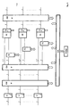
- die Grundstruktur der Vorrichtung mit den Funktionseinheiten Eingangsstufen E, Eingangsmatrix EM, Bearbeitungsstufen FD, Summier- und Pegeldosierungsstufen SE, Ausgangsmatrix AM, "intelligente" Eingabe EA und einer Anzeige;
- Fig. 3
- eine Ergänzung durch die Funktionseinheit Konvertierungsmatrix KM;
- Fig. 4
- eine Ergänzung mit den Funktionseinheiten FE für die Erzeugung eines Tiefsttonkanals zur getrennten Ansteuerung eines sog. Subwoofers;
- Fig. 5
- eine weitere mögliche Ergänzung der Bearbeitungsmöglichkeit jedes Eingangssignals für ergänzende Wiedergabekanäle bei größeren Räumen;
- Fig. 6
- eine Konfiguration für die Bearbeitungsmöglichkeit aller Kanäle.
- Fig. 1
- a comparison of the stereo listening zones in conventional 5-channel playback and when using the invention (hatched area);
- Fig. 2
- the basic structure of the device with the functional units input stages E, input matrix EM, processing stages FD, summing and level metering stages SE, output matrix AM, "intelligent" input EA and a display;
- Fig. 3
- supplemented by the functional unit conversion matrix KM;
- Fig. 4
- a supplement with the functional units FE for the generation of a low-frequency channel for the separate control of a so-called subwoofer;
- Fig. 5
- a further possible addition to the processing possibility of each input signal for additional playback channels in larger rooms;
- Fig. 6
- a configuration for processing all channels.
Der hauptsächliche Effekt der Erfindung ist die in Fig. 1 gezeigte Vergrößerung der Stereo-Hörzone unter Beibehaltung des zu erzielenden komplexen Höreindruckes, der sich bei der bisherigen Zweikanal-Stereofonie auf einen einzigen Bezugsplatz reduzierte, der durch einen Punkt in der Mitte der Hörzone angedeutet ist und bei der standardisierten Mehrkanaltonanordnung (3/2-Anordnung) nur eine geringe Vergrößerung der Hörzone zuläßt, die durch ein inneres weißes Trapez bezeichnet ist. Das innere schraffierte Trapez zeigt die Vergrößerung der Hörzone mit zutreffender Lokalisierung der Schallquellen bei Anwendung der Erfindung. Mit dem äußeren schraffierten Sechseck ist die Möglichkeit der weiteren Vergrößerung der Hörzone mittels zusätzlich abgeleiteter Wiedergabekanäle schematisch gezeigt.The main effect of the invention is that shown in FIG. 1 Enlargement of the stereo listening zone while maintaining the complex auditory impression that can be achieved with the previous Two-channel stereo on a single reference point reduced by a point in the middle of the listening zone is indicated and in the standardized multi-channel sound arrangement (3/2 arrangement) only a small enlargement of the Listening zone allows by an inner white trapeze is designated. The inner hatched trapezoid shows the Enlargement of the listening zone with appropriate localization of the Sound sources when applying the invention. With the outside hatched hexagon is the possibility of further Enlargement of the listening zone by means of an additional derivative Playback channels shown schematically.
Ein weiterer wesentlicher Vorteil bei der Anwendung der Erfindung ergibt sich aus der nicht starr an die Standardanordnung gebundene Plazierung der Lautsprecher im jeweiligen individuellen Wiedergabebereich.Another significant advantage when using the invention results from the not rigidly attached to the standard arrangement bound placement of the speakers in the individual Playback area.
Um auch die vorteilhafte Wiedergabe von Programmbeiträgen zu ermöglichen, die nach einem der Matrixverfahren, z.B. mittels des Dolby-Stereo-Surroundsystems, übertragen werden, ist nach dem üblicherweise eingesetzten Decoder (z.B. Dolby Pro Logic Surround Decoder) eine Vorrichtung nach dem beschriebenen Verfahren erforderlich, die - je nach Wunsch und Vorstellung des Anwenders - sowohl ein fünf- bzw. 5-plus-1-kanalig angebotenes Programm als auch andere ein- oder mehrkanalige Programme verarbeiten kann.To also the advantageous reproduction of program contributions enable that according to one of the matrix methods, e.g. by means of of the Dolby stereo surround system, is transmitted after the decoder usually used (e.g. Dolby Pro Logic Surround decoder) a device according to the described Procedures required - depending on your wishes and ideas of the user - both a five- or 5-plus-1-channel offer Program as well as other single or multi-channel programs can process.
Die für eine mehrkanalige Wiedergabe verfügbare und in einem
Raum unter Beachtung des Standards und der vorhandenen Möglichkeiten
aufgestellte Lautsprecheranordnung wird durch eine
Vorrichtung ergänzt, die nach einem Rundfunk- und/oder TV-Empfänger
bzw. einer Wiedergabeeinrichtung für mehrkanalige
Tonaufzeichnungen und vor die Leistungsstufen der einzelnen
Lautsprecher geschaltet werden muß.
Sie besteht gemäß Fig. 2 aus:
- der Eingangsmatrix EM mit den davorliegenden Eingangsstufen E,
- den Funktionseinheiten FD zur mehrkanaligen, unabhängigen Laufzeit-, Pegel- und ggf. erforderlichen Phasenkorrektur,
- den Summierstufen SE und
- der Ausgangsmatrix AM.
According to FIG. 2 it consists of:
- the input matrix EM with the input stages E in front of it,
- the functional units FD for multi-channel, independent runtime, level and possibly necessary phase correction,
- the summation stages SE and
- the output matrix AM.
Somit sind die Eingänge der Eingangsstufen (1-n) mit den Ausgängen eines mehrkanaligen Empfängers oder anderer ein- oder mehrkanaliger Programmquellen verbunden. Die Ausgänge dieser Eingangsstufen sind mit den Eingängen der Eingangsmatrix EM verbunden. Diese verteilt die vorhandenen Eingangssignale über die Verbindungen zu den Funktionseinheiten FD, so daß jede FD n-1 der verfügbaren Eingangssignale erhält. Die (n-1)-Ausgänge jeder FD werden mit den Eingängen einer Summierstufe SE verbunden. Über eine direkte Verbindung zwischen der Eingangsmatrix EM und jeder Summierstufe SE gelangt jeweils ein unbearbeitetes Eingangssignal in jede Summierstufe, so daß in jeder SE ein Summensignal aus den n Eingangssignalen gebildet werden kann.Thus the inputs of the input stages (1-n) are with the outputs a multi-channel receiver or other one or multi-channel program sources connected. The outputs of this Input stages are with the inputs of the input matrix EM connected. This distributes the existing input signals over the connections to the functional units FD, so that each FD receives n-1 of the available input signals. The (n-1) outputs of each FD are connected to the inputs of a summing stage SE connected. Via a direct connection between the input matrix EM and each summing stage SE each arrive an unprocessed input signal in each summing stage, so that in each SE a sum signal from the n input signals can be formed.
Diese Summensignale unterscheiden sich dadurch, daß in jedem Summensignal verschieden bearbeitete Signale und ein unbearbeitetes Signal aus der Anzahl der eingangsseitig verfügbaren Signale vorhanden sind.These sum signals differ in that in each Sum signal differently processed signals and an unprocessed Signal from the number of inputs available Signals are present.
Die Ausgänge der Summierstufen SE - die ausgangsseitig die Möglichkeit der steuerbaren Pegelbeeinflussung enthalten - werden mit der Ausgangsmatrix AM verbunden, so daß sie mit den vorhandenen angeschlossenen Wiedergabekanälen, d. h. mit den Eingängen der Leistungsverstärker verbunden sind und über die Ausgangsmatrix den entsprechenden Wiedergabekanälen zugeordnet werden.The outputs of the summing stages SE - those on the output side Possibility of controllable level control included - are connected to the output matrix AM so that they are connected to the existing connected playback channels, d. H. With are connected to the inputs of the power amplifiers and via the output matrix is assigned to the corresponding playback channels become.
Bei der Berücksichtigung der mehrkanaligen Wiedergabe eines Programms mit weniger als 5 Signalen kann gemäß Fig. 3 in Ergänzung dieses Funktionskomplexes vor der Eingangsmatrix EM eine Konvertierungsmatrix KM liegen, welche die vorhandenen Eingangssignale auf die Eingangsmatrix EM verteilt.When considering the multi-channel playback of a Programs with fewer than 5 signals can supplement FIG. 3 of this functional complex in front of the input matrix EM a conversion matrix KM, which the existing ones Input signals distributed to the input matrix EM.
In diesem Falle sind die Ausgänge der Eingangsstufen E mit den Eingängen der Konvertierungsmatrix KM verbunden und deren Ausgänge mit den entsprechenden Eingängen der Eingangsmatrix EM.In this case, the outputs of the input stages E are included connected to the inputs of the conversion matrix KM and their Outputs with the corresponding inputs of the input matrix EM.
Sofern ein separater Tieftonkanal nicht im Programmsignal enthalten ist, kann entsprechend Fig.4 zur Erzeugung eines getrennten Tieftonkanals an die Ausgänge der Eingangsstufen E eine Filtereinheit FE-1 geschaltet werden. In dieser werden, wie ebenfalls bekannt, über eine Tiefpaßschaltung aus den vorhandenen Eingangssignalen, vorzugsweise den drei Frontsignalen, die tieffrequenten Signalanteile ausgefiltert, summiert und einem eigenen Tieftonkanal zugeordnet.Unless a separate bass channel is not in the program signal is included, can be used to generate a separate bass channel to the outputs of input stages E a filter unit FE-1 can be switched. In this, as also known, via a low-pass circuit from the existing input signals, preferably the three front signals, the low-frequency signal components filtered out, summed and assigned its own bass channel.
Zwecks Anpassung der Lautsprecher an die vorhandenen Raumbedingungen kann - wie bereits bei der Stereowiedergabe in hochwertigen Heimwiedergabeanordnungen praktiziert - für die Wiedergabekanäle ein weiterer Filterbaustein FE-2 der Ausgangsmatrix nachgeschaltet werden (Fig. 4).To adapt the speakers to the existing room conditions can - as with the stereo playback in high quality home display devices practiced - for that Playback channels another filter module FE-2 of the output matrix are connected downstream (Fig. 4).
Zur akustischen Optimierung dieser Wiedergabeanordnung an die vorhandenen Raumbedingungen, Standorte der Lautsprecher und die gewünschten Hörzone ist dieser speziellen Vorrichtung eine Eingabeeinheit EA zuzuordnen. Diese ermöglicht die Eingabe der Standorte der Lautsprecher, deren Parameter, der vorhandenen Raumbedingungen sowie der gewünschten Hörerplätze, des weiteren die Möglichkeit der Korrektur und Anpassung der Verhältnisse zwischen Direktinformation und gewünschter Rauminformation (R/D) in Abhängigkeit vom Programmaterial.To acoustically optimize this display arrangement to the existing room conditions, locations of the speakers and the desired listening zone is one for this special device Assign input unit EA. This enables the entry the locations of the speakers, their parameters, the existing ones Room conditions and the desired listener positions, the further the possibility of correcting and adjusting the conditions between direct information and desired room information (R / D) depending on the program material.
Diese Eingabeanordnung EA ist steuerungsmäßig mit den einzelnen Baugruppen der gesamten Vorrichtung verbunden und steuert die variabel einstellbaren Parameter der einzelnen Baugruppen. Sie berechnet selbständig Parameter auf der Basis der eingegebenen Raum- und Standortparameter und ordnet sie den entsprechenden Baugruppen zu.This input arrangement EA is in control with the individual Assemblies of the entire device connected and controls the variably adjustable parameters of the individual modules. It calculates parameters independently on the basis of the entered room and location parameters and assigns them to the corresponding assemblies.
Zur optischen Kontrolle der eingegebenen Parameter ist als Ergänzung der Eingabeanordnung eine Anzeige auf einem Display vorgesehen.For visual control of the entered parameters is as Completion of the input arrangement a display on a display intended.
Bei einer Versorgung größerer Hörzonen werden zusätzlich weitere
Funktionseinheiten FD eingefügt, deren Eingänge mit allen
Ausgängen der Eingangsmatrix EM verbunden werden und somit
ein Summensignal aus allen - aber unterschiedlich behandelten
- Eingangssignalen für jeden weiteren Wiedergabekanal
1 bis m, der jeweils mit weiteren verteilten Lautsprechern
verbunden ist, gebildet wird (Fig. 4).If larger hearing zones are supplied, additional ones will be added
Functional units FD inserted, whose inputs with all
Outputs of the input matrix EM are connected and thus
a sum signal from all - but treated differently
- Input signals for each
Diese zulässige Erweiterung der Vorrichtung - jedes Eingangssignal, auch das nicht zu bearbeitende Signal gelangt über eine FD zur Summierstufe - vereinfacht die schaltungstechnische Lösung dieser Vorrichtung, wie Fig. 6 zeigt.This allowable extension of the device - any input signal, the signal not to be processed is also transmitted an FD to the summing stage - simplifies the circuitry Solution of this device, as shown in Fig. 6.
Der Signalfluß bei einem 5-kanaligen Programm ist wie folgt
erklärbar:
Die Signale gelangen von der Quelle (Übertragungskanal, Mehrkanalaufzeichnung
usw.) an die Eingangsstufen E dieser speziellen
Vorrichtung. Sie werden mittels der Eingangsmatrix
auf die vorhandenen Funktionseinheiten FD so verteilt, daß
jeder FD vier dieser 5 verfügbaren Eingangssignale zugeordnet
werden, so daß in jeder FD jeweils ein Signal nicht einer
Parameterkorrektur unterworfen wird. (In der ersten FD wird
das erste Signal unbearbeitet an die nachfolgende Summierstufe
SE geschaltet, in der zweiten FD das zweite usw.).The signal flow for a 5-channel program can be explained as follows:
The signals pass from the source (transmission channel, multi-channel recording, etc.) to the input stages E of this special device. They are distributed to the existing functional units FD by means of the input matrix in such a way that four of these 5 available input signals are assigned to each FD, so that one signal in each FD is not subjected to a parameter correction. (In the first FD, the first signal is switched unprocessed to the subsequent summing stage SE, in the second FD the second, etc.).
In der nachgeschalteten Summierstufe SE werden die vier bezüglich Pegel, Laufzeit und Phase unterschiedlich behandelten Signale und das jeweils einmal unbehandelte Signal wieder summiert und gemeinsam im Pegel korrigiert. Am Ausgang der Ausgangsmatrix AM sind diese Summensignale den vorhandenen Wiedergabekanälen und den daran angeschlossenen Lautsprechern mit ihren Leistungsstufen entsprechend ihrer Funktionsbestimmung (Frontlautsprecher-Surroundlautsprecher) zugeordnet.In the downstream summing stage SE, the four are related Level, duration and phase treated differently Signals and the once untreated signal again summed up and corrected together in level. At the exit of the Output matrix AM, these sum signals are the existing ones Playback channels and the speakers connected to them with their performance levels according to their function definition (Front speaker surround speakers).
In zulässiger Erweiterung der Vorrichtung können die Funktionseinheiten FD so erweitert werden, daß sie eine Parameteränderung für alle Eingangskanäle ermöglichen, so daß für jeden Wiedergabekanal eine Summe aus allen vorhandenen und behandelten Eingabesignalen entsteht (Fig. 6)In a permissible extension of the device, the functional units can FD can be expanded to include a parameter change allow for all input channels, so that for each playback channel a sum of all existing and treated input signals arises (Fig. 6)
Ist den Eingangsstufen eine Filtereinrichtung FE-1 nachgeschaltet, so werden die tieffrequenten Anteile der einzelnen unbearbeiteten Quellsignale ausgefiltert, in der SE summiert und einem gesonderten Tieftonkanal zugeordnet, der über eine Pegelkorrektureinheit einen speziellen Tieftonlautsprecher mit entsprechender Leistungseinheit versorgt.If a filter device FE-1 is connected downstream of the input stages, so are the low frequency parts of each unprocessed source signals filtered out, summed in the SE and assigned a separate bass channel that has a Level correction unit a special woofer supplied with the appropriate power unit.
Die nicht immer dem Standard entsprechende Plazierung der Lautsprecher und die in der Praxis kaum einhaltbare optimale Hörerplatzanordnung sowie die räumlichen Heimbedingungen erfordern in den meisten Anwendungsfällen außerdem eine dem jeweiligen Raum und der gewünschten Hörzone angepaßte Frequenzgangskorrektur der Lautsprecher und ggf. eine Laufzeitkorrektur der Wiedergabekanäle in Abhängigkeit ihres Standortes. Letzteres kann in den FD erfolgen.The placement of the not always according to the standard Speakers and the optimal one that can hardly be kept in practice Arrangement of the handset and the spatial home conditions require in most applications, one for each Frequency response correction adapted to the room and the desired listening zone the loudspeaker and possibly a runtime correction the playback channels depending on their location. The latter can be done in the FD.
Für eine erforderliche Raumanpassung des Frequenzgangs können - entsprechend Fig. 4 und 5 - die Signale an Raumkorrekturfilterbausteinen FE-2 zwischen der Ausgangsmatrix AM und die Eingänge der Leistungsverstärker der Wiedergabekanäle geschaltet werden.For a required spatial adjustment of the frequency response, you can 4 and 5 - the signals at room correction filter modules FE-2 between the output matrix AM and the Inputs of the power amplifiers of the playback channels switched become.
Diese Raumkorrekturfilter ermöglichen es, die Klangfarbe der gesamten Wiedergabeanordnung, durch Veränderungen in den einzelnen Wiedergabekanälen, dem jeweiligen Raum und den Vorstellungen des Anwenders durch die Eingabe von Korrekturwerten anzupassen.These room correction filters allow the timbre of the entire playback arrangement, through changes in each Playback channels, the respective room and the performances of the user by entering correction values adapt.
Die Abweichungen von einer Standardaufstellung sind durch die Eingabe der Standortparameter in die Eingabeeinheit korrigierbar. Durch die Eingabe weiterer Parameter wie Lautsprecherdaten, Hörzone oder Hörerpositionen usw. können sowohl Lautstärkeverhältnisse korrigiert als auch die Hörbedingungen außerhalb eines optimalen Hörerplatzes, insbesondere im Vorzugsbereich (bevorzugte Hörerposition) des Anwenders, optimiert werden.The deviations from a standard list are due to the Entry of the location parameters in the input unit can be corrected. By entering additional parameters such as speaker data, Listening zone or listener positions etc. can both Volume ratios corrected as well as listening conditions outside of an optimal listening position, especially in the preferred area (preferred listener position) of the user, optimized become.
Das Verhältnis zwischen Direktanteil und Surroundanteil kann ebenfalls in Abhängigkeit vom Programmaterial durch die Eingabe entsprechender Korrekturwerte in die vorhandene Eingabeeinheit verändert, gespeichert und dem aktuellen Programm zugeordnet wieder abgerufen werden.The ratio between direct component and surround component can also depending on the program material by entering appropriate correction values in the existing input unit changed, saved and assigned to the current program be retrieved again.
Die Nutzung dieser Vorrichtung auch für die Wiedergabe von Programmaterial mit weniger als fünf Tonkanälen wird durch die vor die Eingangsmatrix EM vorgeschaltete Konvertierungsmatrix KM ermöglicht.The use of this device also for the playback of Program material with less than five audio channels is through the conversion matrix upstream of the input matrix EM KM enables.
Claims (9)
- Method for multi-channel sound reproduction in which the sound signals are recorded in multi-channel and source-oriented manner and in which, prior to being emitted, said multi-channel sound signals are processed by matrixing and summation and are distributed onto front and surround playback channels and optionally also onto a sub-bass channel, characterized in that, after distribution of the sound signals onto at least three front and two surround playback channels, sub-signals are branched off from each of said sound signals and the branched-off sub-signals, differently processed according to their directional assignment, are each summated with an increased propagation delay time, reduced level and at least partially changed phase position to one of the five or more unprocessed sound signals, such that each summation signal contains differently processed sub-signals and an unprocessed sound signal and the directional assignment of the summation signals, including after further similar divisions and summations, to the channels of the three front and two surround playback loudspeakers distributed in the room, and, where applicable, further playback loudspeakers, is effected according to the orientations of the unprocessed sound signals.
- Method according to claim 1, characterized in that the further playback loudspeakers additionally distributed in the room, preferably for surround signals, are supplied with further signals each formed as a sum consisting of the sub-signals - split off from the unprocessed sound signals and differently processed in propagation delay time, level and phase - and an unprocessed sound signal, and in that the changes of amplitude and propagation delay time are selected according to the distance of each further additional playback loudspeaker from the location of the first three front and two surround loudspeakers and the corresponding supply area of the aforementioned additional surround loudspeakers.
- Method according to claim 1, characterized in that there is also a summation of sub-signals exclusively thus branched off from the sound signals and processed, in which summation the summation signal for each playback channel contains a processed sub-signal from each sound signal present at the input.
- Device for multi-channel sound reproduction with a plurality of input connections for at least three front and two surround playback channels in which the inputs are each connected through an input stage to the corresponding input connections of an input matrix (EM), characterized in that the outputs of the input matrix (EM) are connected on the one hand to the same number of input connections of a functional unit (FD) for the in each case separate different correction of the supplied signals with regard to propagation delay time, level and, where applicable, phase for each output of said functional unit (FD) and on the other hand are connected to the first inputs of a summation unit (SE) to the second and/or further inputs of which are connected the outputs of the functional unit (FD), and in that the summation signals each formed from an unchanged input signal at the input stage (E) with differently processed signals of other input signals are connected according to the assignment of the unprocessed input signals to the outputs of an output matrix (AM) for the at least three front and two surround playback channels and, where applicable, further playback loudspeakers.
- Device according to claim 4, characterized in that connected ahead of the input matrix (EM) is a further conversion matrix (KM) which distributes the available sound signals of recordings or broadcasts with fewer than five sound channels, particularly from mono, 2-, 3-, 4-, 5/2-channel stereo surround methods, onto at least five input stages of the input matrix (EM).
- Device according to claim 4, characterized in that connected ahead of the input matrix (EM) in the absence of a separate sub-bass broadcast and/or recording channel is a multi-channel filter unit which contains lowpass circuits (TP) and a summation stage and which filters out and summates the extra-low-frequency components of the available sound channels and assigns same to a separate sub-bass playback channel to the output of which are connected extra-low-frequency loudspeakers and/or subwoofers.
- Device according to claim 4, characterized in that the functional unit (FD) is provided with an input arrangement (EA) for the input of the room conditions of the playback arrangement, according to the loudspeaker positions, and of the desired parameters, with regard to the loudspeaker ratios of front and surround loudspeakers.
- Device according to claim 7, characterized in that the input arrangement (EA) is associated with a display which shows the inputs and the parameters which are to be changed, with regard to propagation delay time correction, level correction, degree-of-correlation correction, etc.
- Device according to claim 7, characterized in that the input arrangement (EA) is provided for further parameters of the sound signals which are to be influenced and is thereby connected to the units (KM, FE, SE, EM) which influence the sound signal paths through their processing elements including the required parameter values from the inputted room parameters and personalized definitions.
Applications Claiming Priority (2)
| Application Number | Priority Date | Filing Date | Title |
|---|---|---|---|
| DE4440014A DE4440014C2 (en) | 1994-11-09 | 1994-11-09 | Method and device for multi-channel sound reproduction |
| DE4440014 | 1994-11-09 |
Publications (3)
| Publication Number | Publication Date |
|---|---|
| EP0712264A2 EP0712264A2 (en) | 1996-05-15 |
| EP0712264A3 EP0712264A3 (en) | 1999-08-18 |
| EP0712264B1 true EP0712264B1 (en) | 2003-11-12 |
Family
ID=6532876
Family Applications (1)
| Application Number | Title | Priority Date | Filing Date |
|---|---|---|---|
| EP95113420A Expired - Lifetime EP0712264B1 (en) | 1994-11-09 | 1995-08-26 | Method and apparatus for multi-channel sound reproduction |
Country Status (4)
| Country | Link |
|---|---|
| US (1) | US5703955A (en) |
| EP (1) | EP0712264B1 (en) |
| AT (1) | ATE254383T1 (en) |
| DE (2) | DE4440014C2 (en) |
Families Citing this family (10)
| Publication number | Priority date | Publication date | Assignee | Title |
|---|---|---|---|---|
| DE19958836A1 (en) | 1999-11-29 | 2001-05-31 | Deutsche Telekom Ag | In car communication system has individual microphones and loudspeakers allows easy conversation |
| DE10052992C2 (en) * | 2000-10-19 | 2002-11-07 | Deutsche Telekom Ag | Process for the spatial reproduction of sound information in video conferences |
| US20040086130A1 (en) * | 2002-05-03 | 2004-05-06 | Eid Bradley F. | Multi-channel sound processing systems |
| DE10300507A1 (en) * | 2003-01-08 | 2004-07-22 | Pmc Gmbh | Subwoofer has at least one rotary knob connected in force-locking manner to axle of control motor attached to subwoofer and addressed by controller that receives its information from input device |
| US6937737B2 (en) * | 2003-10-27 | 2005-08-30 | Britannia Investment Corporation | Multi-channel audio surround sound from front located loudspeakers |
| JP4396646B2 (en) * | 2006-02-07 | 2010-01-13 | ヤマハ株式会社 | Response waveform synthesis method, response waveform synthesis device, acoustic design support device, and acoustic design support program |
| US20100135509A1 (en) * | 2008-12-01 | 2010-06-03 | Charles Timberlake Zeleny | Zeleny sonosphere |
| US9613640B1 (en) * | 2016-01-14 | 2017-04-04 | Audyssey Laboratories, Inc. | Speech/music discrimination |
| WO2019197002A1 (en) * | 2018-04-13 | 2019-10-17 | Aalborg Universitet | Generating sound zones using variable span filters |
| US11431920B2 (en) * | 2021-02-03 | 2022-08-30 | Better Way Productions LLC | 360 degree interactive studio |
Family Cites Families (12)
| Publication number | Priority date | Publication date | Assignee | Title |
|---|---|---|---|---|
| NL172815B (en) * | 1971-04-13 | Sony Corp | MULTIPLE SOUND DISPLAY DEVICE. | |
| DE2143044A1 (en) * | 1971-08-27 | 1973-03-01 | Standard Elektrik Lorenz Ag | METHOD FOR QUASIQUADROPHONIC REPRODUCTION OF TWO-CHANNEL STEREO SIGNALS |
| DD242954A3 (en) * | 1983-12-14 | 1987-02-18 | Deutsche Post Rfz | GREATER SOUND SYSTEM |
| US4589129A (en) * | 1984-02-21 | 1986-05-13 | Kintek, Inc. | Signal decoding system |
| JPH0744759B2 (en) * | 1987-10-29 | 1995-05-15 | ヤマハ株式会社 | Sound field controller |
| DE68921517T2 (en) * | 1988-07-20 | 1996-01-25 | Sanyo Electric Co | Sound player. |
| US5172415A (en) * | 1990-06-08 | 1992-12-15 | Fosgate James W | Surround processor |
| JPH04150200A (en) * | 1990-10-09 | 1992-05-22 | Yamaha Corp | Sound field controller |
| JP3108087B2 (en) * | 1990-10-29 | 2000-11-13 | パイオニア株式会社 | Sound field correction device |
| GB9103207D0 (en) * | 1991-02-15 | 1991-04-03 | Gerzon Michael A | Stereophonic sound reproduction system |
| US5199075A (en) * | 1991-11-14 | 1993-03-30 | Fosgate James W | Surround sound loudspeakers and processor |
| DE4310105A1 (en) * | 1993-03-27 | 1994-09-29 | Blaupunkt Werke Gmbh | Stereophonic sound processor |
-
1994
- 1994-11-09 DE DE4440014A patent/DE4440014C2/en not_active Expired - Lifetime
-
1995
- 1995-06-07 US US08/477,036 patent/US5703955A/en not_active Expired - Lifetime
- 1995-08-26 EP EP95113420A patent/EP0712264B1/en not_active Expired - Lifetime
- 1995-08-26 DE DE59510828T patent/DE59510828D1/en not_active Expired - Lifetime
- 1995-08-26 AT AT95113420T patent/ATE254383T1/en active
Also Published As
| Publication number | Publication date |
|---|---|
| ATE254383T1 (en) | 2003-11-15 |
| EP0712264A2 (en) | 1996-05-15 |
| US5703955A (en) | 1997-12-30 |
| DE4440014A1 (en) | 1996-05-15 |
| DE59510828D1 (en) | 2003-12-18 |
| DE4440014C2 (en) | 2002-02-07 |
| EP0712264A3 (en) | 1999-08-18 |
Similar Documents
| Publication | Publication Date | Title |
|---|---|---|
| DE2616762C2 (en) | Device for expanding a stereophonic sound image | |
| DE2244162C3 (en) | "system | |
| DE19950319A1 (en) | Process for synthesizing a three-dimensional sound field | |
| DE69834466T2 (en) | Apparatus and method for sound image localization | |
| DE2624568A1 (en) | STEREOPHONIC PLAYBACK DEVICE | |
| EP0712264B1 (en) | Method and apparatus for multi-channel sound reproduction | |
| EP2457389A1 (en) | Device and method for improving stereophonic or pseudo-stereophonic audio signals | |
| DE69734884T2 (en) | RECORDING AND REPRODUCTION OF A TWO-CHANNELING SYSTEM FOR HOLOPHONIC SOUND PLAYBACK | |
| DE102021203640B4 (en) | Loudspeaker system with a device and method for generating a first control signal and a second control signal using linearization and/or bandwidth expansion | |
| DE60125259T2 (en) | Sound field correction method in an audio system | |
| EP3090575B1 (en) | Method for audio reproduction in a multi-channel sound system | |
| DE4129918C2 (en) | Sound reproduction device | |
| DE2204668A1 (en) | Multi-channel sound reproduction system | |
| WO1995030323A1 (en) | Process and device for compensating for acoustic distortion | |
| DE10059538A1 (en) | Audio player for 5 channel DVD combines channels for headphones reduces loss of sound information | |
| WO1995033357A1 (en) | Process and equipment for the reproduction of sound signals, and associated control device and sound reproduction device | |
| DE19900961A1 (en) | Method and device for reproducing multi-channel sound signals | |
| DE19980688B3 (en) | Audio playback device | |
| DE19956690A1 (en) | Public address system | |
| EP0025118A1 (en) | Arrangement for the acoustic reproduction of signals, presented by means of a right and a left stereo-channel | |
| DE102005052904A1 (en) | System for reproducing audio signals | |
| DE19628261A1 (en) | Method and device for electronically embedding directional inserts in two-channel sound | |
| DE3001007C2 (en) | Device for recording stereophonic signals | |
| DE3131303A1 (en) | Method for transmitting stereophonic signals | |
| DE10113087B4 (en) | Arrangement for signal processing in a motor vehicle |
Legal Events
| Date | Code | Title | Description |
|---|---|---|---|
| PUAI | Public reference made under article 153(3) epc to a published international application that has entered the european phase |
Free format text: ORIGINAL CODE: 0009012 |
|
| AK | Designated contracting states |
Kind code of ref document: A2 Designated state(s): AT BE CH DE DK ES FR GB GR IE IT LI LU MC NL PT SE |
|
| RAP1 | Party data changed (applicant data changed or rights of an application transferred) |
Owner name: DEUTSCHE TELEKOM AG |
|
| PUAL | Search report despatched |
Free format text: ORIGINAL CODE: 0009013 |
|
| AK | Designated contracting states |
Kind code of ref document: A3 Designated state(s): AT BE CH DE DK ES FR GB GR IE IT LI LU MC NL PT SE |
|
| 17P | Request for examination filed |
Effective date: 20000218 |
|
| 17Q | First examination report despatched |
Effective date: 20020108 |
|
| GRAH | Despatch of communication of intention to grant a patent |
Free format text: ORIGINAL CODE: EPIDOS IGRA |
|
| GRAA | (expected) grant |
Free format text: ORIGINAL CODE: 0009210 |
|
| GRAS | Grant fee paid |
Free format text: ORIGINAL CODE: EPIDOSNIGR3 |
|
| AK | Designated contracting states |
Kind code of ref document: B1 Designated state(s): AT BE CH DE DK ES FR GB GR IE IT LI LU MC NL PT SE |
|
| REG | Reference to a national code |
Ref country code: GB Ref legal event code: FG4D Free format text: NOT ENGLISH |
|
| REG | Reference to a national code |
Ref country code: CH Ref legal event code: NV Representative=s name: ICB INGENIEURS CONSEILS EN BREVETS SA Ref country code: CH Ref legal event code: EP |
|
| REF | Corresponds to: |
Ref document number: 59510828 Country of ref document: DE Date of ref document: 20031218 Kind code of ref document: P |
|
| REG | Reference to a national code |
Ref country code: IE Ref legal event code: FG4D Free format text: GERMAN |
|
| PG25 | Lapsed in a contracting state [announced via postgrant information from national office to epo] |
Ref country code: SE Free format text: LAPSE BECAUSE OF FAILURE TO SUBMIT A TRANSLATION OF THE DESCRIPTION OR TO PAY THE FEE WITHIN THE PRESCRIBED TIME-LIMIT Effective date: 20040212 Ref country code: GR Free format text: LAPSE BECAUSE OF FAILURE TO SUBMIT A TRANSLATION OF THE DESCRIPTION OR TO PAY THE FEE WITHIN THE PRESCRIBED TIME-LIMIT Effective date: 20040212 Ref country code: DK Free format text: LAPSE BECAUSE OF FAILURE TO SUBMIT A TRANSLATION OF THE DESCRIPTION OR TO PAY THE FEE WITHIN THE PRESCRIBED TIME-LIMIT Effective date: 20040212 |
|
| PG25 | Lapsed in a contracting state [announced via postgrant information from national office to epo] |
Ref country code: ES Free format text: LAPSE BECAUSE OF FAILURE TO SUBMIT A TRANSLATION OF THE DESCRIPTION OR TO PAY THE FEE WITHIN THE PRESCRIBED TIME-LIMIT Effective date: 20040223 |
|
| GBT | Gb: translation of ep patent filed (gb section 77(6)(a)/1977) |
Effective date: 20040212 |
|
| ET | Fr: translation filed | ||
| PG25 | Lapsed in a contracting state [announced via postgrant information from national office to epo] |
Ref country code: LU Free format text: LAPSE BECAUSE OF NON-PAYMENT OF DUE FEES Effective date: 20040826 |
|
| PG25 | Lapsed in a contracting state [announced via postgrant information from national office to epo] |
Ref country code: MC Free format text: LAPSE BECAUSE OF NON-PAYMENT OF DUE FEES Effective date: 20040831 |
|
| PLBE | No opposition filed within time limit |
Free format text: ORIGINAL CODE: 0009261 |
|
| STAA | Information on the status of an ep patent application or granted ep patent |
Free format text: STATUS: NO OPPOSITION FILED WITHIN TIME LIMIT |
|
| 26N | No opposition filed |
Effective date: 20040813 |
|
| REG | Reference to a national code |
Ref country code: CH Ref legal event code: PCAR Free format text: ISLER & PEDRAZZINI AG;POSTFACH 1772;8027 ZUERICH (CH) |
|
| PG25 | Lapsed in a contracting state [announced via postgrant information from national office to epo] |
Ref country code: PT Free format text: LAPSE BECAUSE OF NON-PAYMENT OF DUE FEES Effective date: 20040412 |
|
| PGFP | Annual fee paid to national office [announced via postgrant information from national office to epo] |
Ref country code: NL Payment date: 20140821 Year of fee payment: 20 Ref country code: DE Payment date: 20140821 Year of fee payment: 20 Ref country code: IE Payment date: 20140820 Year of fee payment: 20 Ref country code: CH Payment date: 20140821 Year of fee payment: 20 |
|
| PGFP | Annual fee paid to national office [announced via postgrant information from national office to epo] |
Ref country code: FR Payment date: 20140819 Year of fee payment: 20 Ref country code: GB Payment date: 20140821 Year of fee payment: 20 Ref country code: AT Payment date: 20140820 Year of fee payment: 20 |
|
| PGFP | Annual fee paid to national office [announced via postgrant information from national office to epo] |
Ref country code: IT Payment date: 20140827 Year of fee payment: 20 |
|
| PGFP | Annual fee paid to national office [announced via postgrant information from national office to epo] |
Ref country code: BE Payment date: 20140820 Year of fee payment: 20 |
|
| REG | Reference to a national code |
Ref country code: DE Ref legal event code: R071 Ref document number: 59510828 Country of ref document: DE |
|
| REG | Reference to a national code |
Ref country code: NL Ref legal event code: V4 Effective date: 20150826 |
|
| REG | Reference to a national code |
Ref country code: CH Ref legal event code: PL |
|
| REG | Reference to a national code |
Ref country code: GB Ref legal event code: PE20 Expiry date: 20150825 |
|
| REG | Reference to a national code |
Ref country code: IE Ref legal event code: MK9A |
|
| REG | Reference to a national code |
Ref country code: AT Ref legal event code: MK07 Ref document number: 254383 Country of ref document: AT Kind code of ref document: T Effective date: 20150826 |
|
| PG25 | Lapsed in a contracting state [announced via postgrant information from national office to epo] |
Ref country code: GB Free format text: LAPSE BECAUSE OF EXPIRATION OF PROTECTION Effective date: 20150825 Ref country code: IE Free format text: LAPSE BECAUSE OF EXPIRATION OF PROTECTION Effective date: 20150826 |