EP0712106A2 - Navigation system - Google Patents
Navigation system Download PDFInfo
- Publication number
- EP0712106A2 EP0712106A2 EP95308142A EP95308142A EP0712106A2 EP 0712106 A2 EP0712106 A2 EP 0712106A2 EP 95308142 A EP95308142 A EP 95308142A EP 95308142 A EP95308142 A EP 95308142A EP 0712106 A2 EP0712106 A2 EP 0712106A2
- Authority
- EP
- European Patent Office
- Prior art keywords
- navigation system
- schedule data
- displayed
- operational schedule
- map
- Prior art date
- Legal status (The legal status is an assumption and is not a legal conclusion. Google has not performed a legal analysis and makes no representation as to the accuracy of the status listed.)
- Granted
Links
Images


Classifications
-
- G—PHYSICS
- G01—MEASURING; TESTING
- G01C—MEASURING DISTANCES, LEVELS OR BEARINGS; SURVEYING; NAVIGATION; GYROSCOPIC INSTRUMENTS; PHOTOGRAMMETRY OR VIDEOGRAMMETRY
- G01C21/00—Navigation; Navigational instruments not provided for in groups G01C1/00 - G01C19/00
- G01C21/26—Navigation; Navigational instruments not provided for in groups G01C1/00 - G01C19/00 specially adapted for navigation in a road network
- G01C21/34—Route searching; Route guidance
- G01C21/36—Input/output arrangements for on-board computers
- G01C21/3679—Retrieval, searching and output of POI information, e.g. hotels, restaurants, shops, filling stations, parking facilities
- G01C21/3682—Retrieval, searching and output of POI information, e.g. hotels, restaurants, shops, filling stations, parking facilities output of POI information on a road map
-
- G—PHYSICS
- G08—SIGNALLING
- G08G—TRAFFIC CONTROL SYSTEMS
- G08G1/00—Traffic control systems for road vehicles
- G08G1/09—Arrangements for giving variable traffic instructions
- G08G1/0962—Arrangements for giving variable traffic instructions having an indicator mounted inside the vehicle, e.g. giving voice messages
- G08G1/0968—Systems involving transmission of navigation instructions to the vehicle
- G08G1/0969—Systems involving transmission of navigation instructions to the vehicle having a display in the form of a map
-
- G—PHYSICS
- G08—SIGNALLING
- G08G—TRAFFIC CONTROL SYSTEMS
- G08G1/00—Traffic control systems for road vehicles
- G08G1/123—Traffic control systems for road vehicles indicating the position of vehicles, e.g. scheduled vehicles; Managing passenger vehicles circulating according to a fixed timetable, e.g. buses, trains, trams
- G08G1/133—Traffic control systems for road vehicles indicating the position of vehicles, e.g. scheduled vehicles; Managing passenger vehicles circulating according to a fixed timetable, e.g. buses, trains, trams within the vehicle ; Indicators inside the vehicles or at stops
- G08G1/137—Traffic control systems for road vehicles indicating the position of vehicles, e.g. scheduled vehicles; Managing passenger vehicles circulating according to a fixed timetable, e.g. buses, trains, trams within the vehicle ; Indicators inside the vehicles or at stops the indicator being in the form of a map
Definitions
- the present invention relates generally to a navigation system for use on a vehicle such as an automobile and, more particularly, to a vehicle navigation system capable of displaying operational schedule data relating to means of transportation which run along railroads or roads in a map being displayed on a display of the system.
- a vehicle-mounted navigation system is arranged such that it may store map data by means of a memory medium such as a CD-ROM and display the current location of a vehicle, detected by means of a GPS receiver and the like, in a predetermined range of map incorporating the detected location, which is read from the CD-ROM and displayed on a display of the system.
- a memory medium such as a CD-ROM
- the known system comprises a location detector, a CD-ROM, a processor, a display and other electronic devices and is thus relatively expensive, thus leaving a desire for its improved cost performance when taken in conjunction with added functions of the system.
- the navigation system is arranged to perform, additionally to the conventional function of determining the current location of a moving object and displaying the determined location of the moving object in read map data incorporating the detected location, two new functions, namely, one of storing operational schedule data of transportation means which run along at least one of railroad, road, water or air routes included in the map data, and the other of reading the operational schedule data of the means of transportation included in map data being displayed and displaying the read data on a display of the system.
- the system of the present invention is thus capable of displaying information relative to the means of transportation, leading to improved cost performance thereof.
- inventive navigation system which is formed by addition to a known system of a CD-ROM and the like for storing data relative to the means of transportation and by addition of partial control program for allowing display of the transportation means data, to a control program in a processor of the known system. Consequently, the inventive navigation system achieves added functions with addition of least hardware, thus enhancing its cost performance.
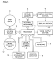
- Fig. 1 shows a navigation system according to the present invention in block diagram.
- the navigation system is comprised of a processor 1, a location detector 2, a clock section (timer) 3 having a calendar function such as years, months, days and days of week, a keyboard 4, a CD-ROM reader 5, map data 6 stored in a CD-ROM, a plotting processor 7, a picture memory 8, a display control section 9, a display section 10 and a voice output section 11.
- Designated by reference numerals 12 and 13 are transportation means operational schedule data (timetable, etc. ) stored in the CD-ROM and traffic information receiver.
- the processor 1 reads the current location of a vehicle carrying the navigation system from the location detector 2, which is formed of a GPS receiver and the like.
- the current location is represented in the form of absolute positions of the Earth, such as x degrees of north latitude and y degrees of east longitude.
- the processor 1 Based on the read current location and display magnification, designated by a command input through the keyboard 4, of a picture to be displayed, the processor 1 computes the latitude of the top and bottom marginal edges and the longitude of the right and left marginal edges of the picture to be displayed.
- the processor 1 reads, by means of the CD-ROM reader 5, map data, which may be accommodated within a field defined by the computed top and bottom and right and left marginal edges, from the map data 6 stored in the CD-ROM and transfers the read map data to the plotting processor 7.
- the plotting processor 7 receives the map data transferred from the processor 1, executes the command contained in the map data to generate graphic data in the form of dot patterns, representative of roads, railroads and stations, which are component elements of the relevant map, and writes the graphic data in a predetermined portion of the picture memory 8.
- the plotting processor 7 transforms character codes contained in the map data received from the processor 1 into corresponding dot pattern characters and writes the resulting data in a predetermined portion of the picture memory 8.
- the map in the form of dot pattern, wrote in the picture memory 8, are periodically read under the control of the display control section 9 and displayed on the display section 10 formed of a liquid crystal panel or a Braun tube (CRT).
- the display section 10 formed of a liquid crystal panel or a Braun tube (CRT).
- the current vehicle location detected by means of the location detector 2 is displayed by way of predetermined codes.
- the processor 1 communicates speech information necessary for the navigation to a vehicle driver through the voice output section 11 having a loud speaker, etc.
- the navigation system includes operation schedule data (timetable, etc. ) 12 of transportation means, stored in the CD-ROM required for displaying operational schedule information of the transportation means, and the traffic information receiver 13.
- the operation schedule data 12 of the transportation means include railroads and names of bus-route streets, which are present in each area defined by latitudinal and longitudinal limits in combination; operational timetable of trains and buses that move or run along the railroads and streets; and locations of each train and bus, which are defined jointly by the latitude and longitude at each predetermined time interval.
- the processor 1 retrieves railroads and roads which are present in a display area defined by the latitudinal and longitudinal limits in combination and being displayed on the display 10, determines the locations of trains and/or buses operating on or along the railroads and roads and communicates their display positions to the plotting processor 7.
- the plotting processor 7 Upon receipt of such communication, the plotting processor 7 writes graphics of the trains in that portion of the picture memory 8 which corresponds to the display positions of the trains and writes graphics of the buses in that portion of the picture memory 8 which corresponds to the display positions of the buses.
- the current locations of train Al and bus A2 are displayed on the screen of the display section 10 together with the location P of the vehicle represented by a triangle, as illustrated in Fig. 2.
- the vehicle driver may be warned of an approaching train by way of a message or a buzz through a loud speaker and the like of the voice output section 11.
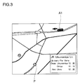
- the operation timetable of the displayed train is displayed at a corner of the screen, as shown in Fig. 3.
- the display section 10 may preferably be in the form of a touch-panel designed to display such operational time schedule by pressing with a finger of the driver of the graphics of the train being displayed.
- the driver can input a command through the keyboard 4, which forms a command input section, so that the operation time table of a train following the train being displayed may be displayed. It is also possible to display the current location of a particular train on the screen by inputting the name or identification number of the train through the keyboard 4.
- Traffic information receiver 13 receives the operation conditions of transportation means, transmitted via a radio circuit, and transmits the received data to the processor 1. Based on the operation conditions transmitted from the traffic information receiver 13, the processor 1 adjusts the current location of the train or bus, as well as the operation timetable thereof.
- Fig. 4 is a flow chart showing operation for map retrieval by use of a cursor.
- the processor 1 determines a cursor position on the displayed map designated by an image position designator (pointing device) such as a mouse and a cursor key of the keyboard 4 as the vehicle remains stable (S1).
- the processor 1 determines the display magnification (scale level) of a map to be displayed on the screen (S2).
- the processor 1 determines whether the vehicle of the operator or driver is located within the map area or field displayed on the screen on the designated scale with the designated cursor position at its center (S3) and causes the current location, marked by, for example, a triangle and referenced P, of the vehicle to be displayed when the vehicle is within the map field being displayed (S4). Thereafter, the processor 1 determines whether the public transportation means, designated by the driver through the keyboard 4, is positioned within the map field being displayed on the screen (S5) and executes the processing of Fig. 6 when the transportation means is present therein.
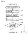
- Fig. 5 is a flow chart showing operation in which the current vehicle location is displayed.
- the processor 1 determines the current location of the vehicle (S11), whereafter it reads map data incorporating or encompassing the current vehicle location from the CD-ROM and displays the corresponding map and the current vehicle location on the screen (S12). Thereafter, the processor 1 determines the scale level of the map being displayed on the screen (S13), determines whether the designated transportation means is located within the displayed map field with the current vehicle location at its center (S14) and follows the operation steps of Fig. 6 when the designated transportation means is present therein.
- Fig. 6 is a flow chart showing operations involved in computing and displaying the location of the designated transportation means.
- the processor 1 determines the current time and date based on the day/time data of the clock section (timer) 3 (S31).
- the processor 1 retrieves two nodes (e.g., train stations and bus stops) having respective operational schedule data (diagram data) and being in close proximity to the vehicle location (S32).
- the processor 1 determines whether there is transportation means (train or bus) currently operating or running between the two retrieved nodes (stations or bus stops)(S33).
- the processor 1 estimates the current operational location of the transportation means (train or bus) on the basis of the service or operation distance between the two nodes (stations or bus stops) and operational schedule data (diagram data) (S34) and displays a mark representing the estimate operational location of the transportation means on the screen in merged or synthesized relations with the map also displayed thereon (S35).
- the processing steps shown in Fig. 4 - Fig. 6 are carried out at predetermined time intervals. These predetermined time intervals should preferably be set to vary depending on the scales of reduction (scale levels) of the maps displayed. For example, when a small scale of reduction is employed to display a narrow region of a map on an enlarged scale, the repeat time (predetermined time) with respect to the processing steps of Fig. 4 - Fig. 6 should be made short so that the moving location of the running transportation means (train or bus) can be precisely displayed.
- Fig. 7 illustrates example forms of nodes of the means of transportation. Different nodes are employed depending on the kinds of transportation means. In the illustrated example, two different nodes are employed, namely, a railroad (route) node and a station node. Each node has data such as location, distance to an adjacent node and railroad name (line name). Each station node has the operational schedule (diagram) data of the relevant transportation means.
- a railroad (route) node and a station node.
- Each node has data such as location, distance to an adjacent node and railroad name (line name).
- Each station node has the operational schedule (diagram) data of the relevant transportation means.
- Fig. 8 illustrates a screen displaying a picture retrieved from the transportation means operation schedule data 12 in which the operational schedule data of a private airplane A3 flying over the vehicle are incorporated.
- the airplane A3 is displayed when a large field is displayed on the screen.
- displaying the airplane A3 on the screen would rather serve for the purpose of amusement than for the purpose of practical uses.
- the navigation system is arranged to display trains and buses on the screen in graphic form
- the locations of the trains and buses may be displayed by flickering of luminous points lights, instead of by such graphic forms.
- the system may be arranged to display only the operation timetable, omitting the location displaying function.
- the system has been described as incorporating the traffic information receiver 13 so that the operational conditions of trains and buses can be adjusted but such arrangement may be omitted when so desired as to lower the cost of production of the system. Contrarily, instead of recording the operational schedule data of the transportation means in the CD-ROM in advance, such data may be received by means of the traffic information receiver 13 and stored in a memory within the processor 1.
- the arrangement with the transportation operation schedule data including positions, designated jointly by the latitude and longitude at each predetermined time, of trains and buses.
- the arrangement may be constructed such that the positions of the trains and buses at each predetermined time will be computed by the processor 1 based upon the time of departure from train stations and bus stops and current time.
- a mode of display may be employed in which the background map is scrolled in response to movement of the vehicle whilst the vehicle is constantly displayed at the center of the screen.
- the scroll mode of display it is difficult to determine the direction of run and speed of movement of a bus.
- a mode of display may be employed in which display positions are discretely altered every time positional displacement exceeds a predetermined value, instead of continuously varying the bus location.
- the moving object carrying the navigation system according to the present invention has been described as a vehicle but the navigation system may also be mounted on other moving objects such as boats.
- the navigation system As thus far explained in detail, by addition of only the operational schedule data of means of transportation and required processing program, the navigation system according to the present invention is provided with the new function of displaying information relative to the transportation means on the screen, whereby its cost performance is improved.
- the system With capability of displaying train information, the system is particularly useful in that when passing an invisible railroad crossing, a train approaching the crossing can be displayed, thus increasing safety at the crossing.
Abstract
Description
- The present invention relates generally to a navigation system for use on a vehicle such as an automobile and, more particularly, to a vehicle navigation system capable of displaying operational schedule data relating to means of transportation which run along railroads or roads in a map being displayed on a display of the system.
- Normally, a vehicle-mounted navigation system is arranged such that it may store map data by means of a memory medium such as a CD-ROM and display the current location of a vehicle, detected by means of a GPS receiver and the like, in a predetermined range of map incorporating the detected location, which is read from the CD-ROM and displayed on a display of the system.
- As a consequence, the known system comprises a location detector, a CD-ROM, a processor, a display and other electronic devices and is thus relatively expensive, thus leaving a desire for its improved cost performance when taken in conjunction with added functions of the system.
- It is therefore an object of the present invention to provide an improved navigation system which achieves added functions with addition of least hardware which are expensive.
- The navigation system according to the present invention is arranged to perform, additionally to the conventional function of determining the current location of a moving object and displaying the determined location of the moving object in read map data incorporating the detected location, two new functions, namely, one of storing operational schedule data of transportation means which run along at least one of railroad, road, water or air routes included in the map data, and the other of reading the operational schedule data of the means of transportation included in map data being displayed and displaying the read data on a display of the system. The system of the present invention is thus capable of displaying information relative to the means of transportation, leading to improved cost performance thereof.
- Due to unexpected traffic jams, vehicle drivers and fellow passengers often miss the trains or other transportation means scheduled to get on board, in which instance the drivers and fellow passengers can easily find out the departure time, as well as the time of arrival at the intended destination, of the following train from the operational schedule data displayed on the display of the navigation system. With some known navigation systems, difficulty is often experienced in correctly detecting the current vehicle location in that the names of displayed railway lines can not be determined. By contrast, with the system according to the present invention, it is possible to easily find out the names of the displayed railway lines by displaying the operational schedule data of the lines. With the inventive system, it is also possible to have an approaching train displayed, whereby safety at invisible railroad crossings may be enhanced.
- With the inventive system, it is further possible to display, for purposes of amusement, data representative of the destination of an airplane flying over a vehicle carrying the system. These useful new functions may be achieved by the inventive navigation system which is formed by addition to a known system of a CD-ROM and the like for storing data relative to the means of transportation and by addition of partial control program for allowing display of the transportation means data, to a control program in a processor of the known system. Consequently, the inventive navigation system achieves added functions with addition of least hardware, thus enhancing its cost performance.
- A preferred embodiment of the present invention will now be described in detail, by way of example only, with reference to the accompanying drawings, in which:
- Fig. 1 is a block diagram illustrating a navigation system according to the present invention;
- Fig. 2 is a schematic view illustrating a sample picture displayed on a screen of the system;
- Fig. 3 is a schematic view illustrating a sample picture displayed together with operational schedule data on the screen;
- Fig. 4 is a flow chart showing operation for retrieving a map by means of a cursor;
- Fig. 5 is a flow chart showing operation for displaying the current location of a vehicle;
- Fig. 6 is a flow chart showing operation for computing the current location of public transportation means and displaying the computed location;
- Fig. 7 is a schematic view illustrating a specific example of a node; and
- Fig. 8 is a schematic view illustrating another sample picture displayed on the screen.
- Initially, reference is taken to Fig. 1, which shows a navigation system according to the present invention in block diagram. As shown in the figure, the navigation system is comprised of a
processor 1, alocation detector 2, a clock section (timer) 3 having a calendar function such as years, months, days and days of week, akeyboard 4, a CD-ROM reader 5,map data 6 stored in a CD-ROM, aplotting processor 7, apicture memory 8, adisplay control section 9, adisplay section 10 and avoice output section 11. Designated byreference numerals - The
processor 1 reads the current location of a vehicle carrying the navigation system from thelocation detector 2, which is formed of a GPS receiver and the like. The current location is represented in the form of absolute positions of the Earth, such as x degrees of north latitude and y degrees of east longitude. Based on the read current location and display magnification, designated by a command input through thekeyboard 4, of a picture to be displayed, theprocessor 1 computes the latitude of the top and bottom marginal edges and the longitude of the right and left marginal edges of the picture to be displayed. Then, theprocessor 1 reads, by means of the CD-ROM reader 5, map data, which may be accommodated within a field defined by the computed top and bottom and right and left marginal edges, from themap data 6 stored in the CD-ROM and transfers the read map data to the plottingprocessor 7. - The plotting
processor 7 receives the map data transferred from theprocessor 1, executes the command contained in the map data to generate graphic data in the form of dot patterns, representative of roads, railroads and stations, which are component elements of the relevant map, and writes the graphic data in a predetermined portion of thepicture memory 8. The plottingprocessor 7 transforms character codes contained in the map data received from theprocessor 1 into corresponding dot pattern characters and writes the resulting data in a predetermined portion of thepicture memory 8. - The map in the form of dot pattern, wrote in the
picture memory 8, are periodically read under the control of thedisplay control section 9 and displayed on thedisplay section 10 formed of a liquid crystal panel or a Braun tube (CRT). In the map displayed on thedisplay 10, the current vehicle location detected by means of thelocation detector 2 is displayed by way of predetermined codes. Theprocessor 1 communicates speech information necessary for the navigation to a vehicle driver through thevoice output section 11 having a loud speaker, etc. - Apart from the features required for a known navigation system, the navigation system according to the preferred embodiment being described includes operation schedule data (timetable, etc. ) 12 of transportation means, stored in the CD-ROM required for displaying operational schedule information of the transportation means, and the
traffic information receiver 13. Theoperation schedule data 12 of the transportation means include railroads and names of bus-route streets, which are present in each area defined by latitudinal and longitudinal limits in combination; operational timetable of trains and buses that move or run along the railroads and streets; and locations of each train and bus, which are defined jointly by the latitude and longitude at each predetermined time interval. - By reading the transportation means
data 12 via the CD-ROM reader 5, theprocessor 1 retrieves railroads and roads which are present in a display area defined by the latitudinal and longitudinal limits in combination and being displayed on thedisplay 10, determines the locations of trains and/or buses operating on or along the railroads and roads and communicates their display positions to the plottingprocessor 7. Upon receipt of such communication, the plottingprocessor 7 writes graphics of the trains in that portion of thepicture memory 8 which corresponds to the display positions of the trains and writes graphics of the buses in that portion of thepicture memory 8 which corresponds to the display positions of the buses. As a result, the current locations of train Al and bus A2 are displayed on the screen of thedisplay section 10 together with the location P of the vehicle represented by a triangle, as illustrated in Fig. 2. As the vehicle approaches a railroad crossing, the vehicle driver may be warned of an approaching train by way of a message or a buzz through a loud speaker and the like of thevoice output section 11. - As the driver inputs through the keyboard 4 a command for displaying the operation timetable of the train being displayed, the operation timetable of the displayed train is displayed at a corner of the screen, as shown in Fig. 3. To simplify operation for the driver, the
display section 10 may preferably be in the form of a touch-panel designed to display such operational time schedule by pressing with a finger of the driver of the graphics of the train being displayed. When desired, the driver can input a command through thekeyboard 4, which forms a command input section, so that the operation time table of a train following the train being displayed may be displayed. It is also possible to display the current location of a particular train on the screen by inputting the name or identification number of the train through thekeyboard 4. -
Traffic information receiver 13 receives the operation conditions of transportation means, transmitted via a radio circuit, and transmits the received data to theprocessor 1. Based on the operation conditions transmitted from thetraffic information receiver 13, theprocessor 1 adjusts the current location of the train or bus, as well as the operation timetable thereof. - Referring now to the flow charts of Fig. 4 - Fig. 6, operation of the navigation system according to the present invention will be discussed. Fig. 4 is a flow chart showing operation for map retrieval by use of a cursor. The
processor 1 determines a cursor position on the displayed map designated by an image position designator (pointing device) such as a mouse and a cursor key of thekeyboard 4 as the vehicle remains stable (S1). Next, theprocessor 1 determines the display magnification (scale level) of a map to be displayed on the screen (S2). Then, theprocessor 1 determines whether the vehicle of the operator or driver is located within the map area or field displayed on the screen on the designated scale with the designated cursor position at its center (S3) and causes the current location, marked by, for example, a triangle and referenced P, of the vehicle to be displayed when the vehicle is within the map field being displayed (S4). Thereafter, theprocessor 1 determines whether the public transportation means, designated by the driver through thekeyboard 4, is positioned within the map field being displayed on the screen (S5) and executes the processing of Fig. 6 when the transportation means is present therein. - Fig. 5 is a flow chart showing operation in which the current vehicle location is displayed. Based on the location data output from the
location detector 2, theprocessor 1 determines the current location of the vehicle (S11), whereafter it reads map data incorporating or encompassing the current vehicle location from the CD-ROM and displays the corresponding map and the current vehicle location on the screen (S12). Thereafter, theprocessor 1 determines the scale level of the map being displayed on the screen (S13), determines whether the designated transportation means is located within the displayed map field with the current vehicle location at its center (S14) and follows the operation steps of Fig. 6 when the designated transportation means is present therein. - Fig. 6 is a flow chart showing operations involved in computing and displaying the location of the designated transportation means. The
processor 1 determines the current time and date based on the day/time data of the clock section (timer) 3 (S31). Next, having reference to the operational schedule data (diagram data) of the transportation means designated by the driver, theprocessor 1 retrieves two nodes (e.g., train stations and bus stops) having respective operational schedule data (diagram data) and being in close proximity to the vehicle location (S32). Then, based on the operational schedule data (diagram data) of transportation means, theprocessor 1 determines whether there is transportation means (train or bus) currently operating or running between the two retrieved nodes (stations or bus stops)(S33). When there are transportation means currently operating between the two nodes (stations or bus stops), theprocessor 1 estimates the current operational location of the transportation means (train or bus) on the basis of the service or operation distance between the two nodes (stations or bus stops) and operational schedule data (diagram data) (S34) and displays a mark representing the estimate operational location of the transportation means on the screen in merged or synthesized relations with the map also displayed thereon (S35). - The processing steps shown in Fig. 4 - Fig. 6 are carried out at predetermined time intervals. These predetermined time intervals should preferably be set to vary depending on the scales of reduction (scale levels) of the maps displayed. For example, when a small scale of reduction is employed to display a narrow region of a map on an enlarged scale, the repeat time (predetermined time) with respect to the processing steps of Fig. 4 - Fig. 6 should be made short so that the moving location of the running transportation means (train or bus) can be precisely displayed.
- Fig. 7 illustrates example forms of nodes of the means of transportation. Different nodes are employed depending on the kinds of transportation means. In the illustrated example, two different nodes are employed, namely, a railroad (route) node and a station node. Each node has data such as location, distance to an adjacent node and railroad name (line name). Each station node has the operational schedule (diagram) data of the relevant transportation means.
- Fig. 8 illustrates a screen displaying a picture retrieved from the transportation means
operation schedule data 12 in which the operational schedule data of a private airplane A3 flying over the vehicle are incorporated. Preferably, the airplane A3 is displayed when a large field is displayed on the screen. In light of the significant differences in speeds of the vehicle and airplane, displaying the airplane A3 on the screen would rather serve for the purpose of amusement than for the purpose of practical uses. - Although the navigation system according to the embodiment described above is arranged to display trains and buses on the screen in graphic form, alternative arrangements are also possible. For example, the locations of the trains and buses may be displayed by flickering of luminous points lights, instead of by such graphic forms. When desired, the system may be arranged to display only the operation timetable, omitting the location displaying function.
- The system has been described as incorporating the
traffic information receiver 13 so that the operational conditions of trains and buses can be adjusted but such arrangement may be omitted when so desired as to lower the cost of production of the system. Contrarily, instead of recording the operational schedule data of the transportation means in the CD-ROM in advance, such data may be received by means of thetraffic information receiver 13 and stored in a memory within theprocessor 1. - Description has been made on the arrangement with the transportation operation schedule data including positions, designated jointly by the latitude and longitude at each predetermined time, of trains and buses. As an alteration, the arrangement may be constructed such that the positions of the trains and buses at each predetermined time will be computed by the
processor 1 based upon the time of departure from train stations and bus stops and current time. - Instead of the mode of display as shown in Fig. 2, separate mode of display may be employed in which the background map is scrolled in response to movement of the vehicle whilst the vehicle is constantly displayed at the center of the screen. In the scroll mode of display, it is difficult to determine the direction of run and speed of movement of a bus. In this instance, a mode of display may be employed in which display positions are discretely altered every time positional displacement exceeds a predetermined value, instead of continuously varying the bus location.
- Although the system has been described as including trains, buses and private airplanes as examples of the transportation means to be displayed, subways, boats and the like may also be included as the means of transportation.
- The moving object carrying the navigation system according to the present invention has been described as a vehicle but the navigation system may also be mounted on other moving objects such as boats.
- As thus far explained in detail, by addition of only the operational schedule data of means of transportation and required processing program, the navigation system according to the present invention is provided with the new function of displaying information relative to the transportation means on the screen, whereby its cost performance is improved.
- With capability of displaying train information, the system is particularly useful in that when passing an invisible railroad crossing, a train approaching the crossing can be displayed, thus increasing safety at the crossing.
Claims (4)
- A navigation system adapted to be capable of determining the current location of a moving object, reading data of a map incorporating the determined current location and displaying the current location of the moving object together with the map on a screen (10), said navigation system comprising:operational schedule data storage means (12) for storing operational schedule data of transportation means operating along at least one of railroad, road, water and air routes contained in said map data; anddisplay means (9,10) for reading said operational schedule data from said operational schedule data storage means (12) and displaying said operational schedule data on the screen (10).
- The navigation system of Claim 1, wherein said display means (9,10) is adapted to display operation location of at least one of a train, a bus and an airplane in accordance with said operational schedule data, read from said operational schedule data storage means, of said transportation means.
- The navigation system of Claim 2, including separate graphics corresponding to said train, bus and airplane, wherein said train, bus and airplane are displayed in the form of respective graphics on the screen (10).
- The navigation system of Claim 1, 2 or 3, wherein said moving object is a vehicle.
Applications Claiming Priority (3)
| Application Number | Priority Date | Filing Date | Title |
|---|---|---|---|
| JP304346/94 | 1994-11-14 | ||
| JP30434694A JP3495118B2 (en) | 1994-11-14 | 1994-11-14 | Navigation device |
| JP30434694 | 1994-11-14 |
Publications (3)
| Publication Number | Publication Date |
|---|---|
| EP0712106A2 true EP0712106A2 (en) | 1996-05-15 |
| EP0712106A3 EP0712106A3 (en) | 1997-06-11 |
| EP0712106B1 EP0712106B1 (en) | 2001-09-05 |
Family
ID=17931913
Family Applications (1)
| Application Number | Title | Priority Date | Filing Date |
|---|---|---|---|
| EP95308142A Expired - Lifetime EP0712106B1 (en) | 1994-11-14 | 1995-11-14 | Navigation system |
Country Status (4)
| Country | Link |
|---|---|
| US (1) | US5765122A (en) |
| EP (1) | EP0712106B1 (en) |
| JP (1) | JP3495118B2 (en) |
| DE (1) | DE69522533T2 (en) |
Cited By (3)
| Publication number | Priority date | Publication date | Assignee | Title |
|---|---|---|---|---|
| EP0947970A1 (en) * | 1998-03-18 | 1999-10-06 | Mentz Datenverarbeitung GmbH | Geographical referencing of public transport networks |
| EP1072862A1 (en) * | 1999-07-29 | 2001-01-31 | Robert Bosch Gmbh | Navigation method and device |
| AT509312B1 (en) * | 2010-01-14 | 2012-12-15 | Thales Rail Signalling Solutions Gesmbh | METHOD FOR THE INFORMATION TRANSMISSION TO TRANSPORT PARTICIPANTS |
Families Citing this family (15)
| Publication number | Priority date | Publication date | Assignee | Title |
|---|---|---|---|---|
| KR100296666B1 (en) * | 1996-05-31 | 2001-08-07 | 하기와라 가즈토시 | Navigation Apparatus |
| WO1998035333A1 (en) * | 1997-02-07 | 1998-08-13 | Casio Computer Co., Ltd. | Network system for serving information to mobile terminal apparatus |
| JPH112533A (en) * | 1997-06-12 | 1999-01-06 | Matsushita Electric Ind Co Ltd | Route guide device |
| EP1055911A4 (en) * | 1998-11-30 | 2003-04-23 | Mitsubishi Electric Corp | Navigator |
| JP2003106849A (en) * | 2001-09-28 | 2003-04-09 | Clarion Co Ltd | Traveling member position displaying system and method therefor, data managing server of traveling member position displaying system as well as use side traveling member terminal of traveling member position displaying system |
| JP4737900B2 (en) * | 2001-09-28 | 2011-08-03 | クラリオン株式会社 | Mobile object approach warning system and method, and use side mobile terminal of mobile object approach warning system |
| JP2005056002A (en) * | 2003-08-07 | 2005-03-03 | Aisin Aw Co Ltd | Information processing center, information processing method and information providing system |
| US7688222B2 (en) | 2003-09-18 | 2010-03-30 | Spot Devices, Inc. | Methods, systems and devices related to road mounted indicators for providing visual indications to approaching traffic |
| US20070106434A1 (en) * | 2005-11-07 | 2007-05-10 | Galbraith Robert E Ii | User interface for railroad dispatch monitoring of a geographic region and display system employing a common data format for displaying information from different and diverse railroad CAD systems |
| US20080059273A1 (en) * | 2006-02-21 | 2008-03-06 | Dynamic Intelligence Inc. | Strategic planning |
| US8260650B2 (en) * | 2006-02-21 | 2012-09-04 | Intelligent Ip Corp. | Transportation scheduling system |
| US8150568B1 (en) * | 2006-11-16 | 2012-04-03 | Robert Gray | Rail synthetic vision system |
| RU2580335C1 (en) * | 2014-10-17 | 2016-04-10 | Общество С Ограниченной Ответственностью "Яндекс" | Method of processing map data |
| CN104613967B (en) * | 2015-01-23 | 2017-03-29 | 中国民航大学 | The chart management method of portable airborne navigation system |
| DE102023004236A1 (en) | 2023-10-21 | 2024-01-11 | Mercedes-Benz Group AG | Method for navigating a vehicle |
Citations (1)
| Publication number | Priority date | Publication date | Assignee | Title |
|---|---|---|---|---|
| EP0532158A1 (en) * | 1991-08-29 | 1993-03-17 | Pioneer Electronic Corporation | Navigation apparatus |
Family Cites Families (4)
| Publication number | Priority date | Publication date | Assignee | Title |
|---|---|---|---|---|
| DE3689139T2 (en) * | 1985-10-25 | 1994-04-07 | Mitsubishi Electric Corp | Bus service control system. |
| US5220507A (en) * | 1990-11-08 | 1993-06-15 | Motorola, Inc. | Land vehicle multiple navigation route apparatus |
| JPH05158405A (en) * | 1991-12-11 | 1993-06-25 | Hitachi Ltd | Path input device |
| US5559707A (en) * | 1994-06-24 | 1996-09-24 | Delorme Publishing Company | Computer aided routing system |
-
1994
- 1994-11-14 JP JP30434694A patent/JP3495118B2/en not_active Expired - Lifetime
-
1995
- 1995-11-13 US US08/556,610 patent/US5765122A/en not_active Expired - Lifetime
- 1995-11-14 EP EP95308142A patent/EP0712106B1/en not_active Expired - Lifetime
- 1995-11-14 DE DE69522533T patent/DE69522533T2/en not_active Expired - Lifetime
Patent Citations (1)
| Publication number | Priority date | Publication date | Assignee | Title |
|---|---|---|---|---|
| EP0532158A1 (en) * | 1991-08-29 | 1993-03-17 | Pioneer Electronic Corporation | Navigation apparatus |
Cited By (4)
| Publication number | Priority date | Publication date | Assignee | Title |
|---|---|---|---|---|
| EP0947970A1 (en) * | 1998-03-18 | 1999-10-06 | Mentz Datenverarbeitung GmbH | Geographical referencing of public transport networks |
| EP1072862A1 (en) * | 1999-07-29 | 2001-01-31 | Robert Bosch Gmbh | Navigation method and device |
| US6477462B1 (en) | 1999-07-29 | 2002-11-05 | Robert Bosch Gmbh | Transfer location navigation method and arrangement |
| AT509312B1 (en) * | 2010-01-14 | 2012-12-15 | Thales Rail Signalling Solutions Gesmbh | METHOD FOR THE INFORMATION TRANSMISSION TO TRANSPORT PARTICIPANTS |
Also Published As
| Publication number | Publication date |
|---|---|
| JP3495118B2 (en) | 2004-02-09 |
| DE69522533T2 (en) | 2002-04-18 |
| US5765122A (en) | 1998-06-09 |
| JPH08136272A (en) | 1996-05-31 |
| EP0712106A3 (en) | 1997-06-11 |
| DE69522533D1 (en) | 2001-10-11 |
| EP0712106B1 (en) | 2001-09-05 |
Similar Documents
| Publication | Publication Date | Title |
|---|---|---|
| EP0712106B1 (en) | Navigation system | |
| US6006161A (en) | Land vehicle navigation system with multi-screen mode selectivity | |
| EP0524814B1 (en) | Navigation device | |
| US7135961B1 (en) | Method and system for providing directions for driving | |
| JP3260722B2 (en) | Map display device | |
| JP3501390B2 (en) | Car navigation system | |
| EP0720003A1 (en) | Navigation device | |
| JP2005233973A (en) | Navigation device using single integrated type print data input card | |
| KR19980079760A (en) | Traffic information display | |
| US6253153B1 (en) | Vehicle navigation system and method | |
| JP2001174271A (en) | Navigation apparatus | |
| JP2005308475A (en) | Vehicle-mounted information terminal | |
| JP3228191B2 (en) | Navigation device and storage medium | |
| JPH06300576A (en) | Running position display device | |
| JP2925358B2 (en) | Residential land navigation system | |
| JPH029689B2 (en) | ||
| JP3590086B2 (en) | Car navigation system | |
| JP3594673B2 (en) | Traffic information display | |
| JP3209774B2 (en) | Map display device | |
| JPS63197986A (en) | Traffic system by spot number display | |
| JPH06162393A (en) | Method for drawing map in on-vehicle navigator | |
| JPH0668393A (en) | Vehicle guiding device | |
| JP2895168B2 (en) | Traffic information providing system using portable storage media | |
| JP3819920B2 (en) | Car navigation system | |
| Robb | Route information systems for motorists |
Legal Events
| Date | Code | Title | Description |
|---|---|---|---|
| PUAI | Public reference made under article 153(3) epc to a published international application that has entered the european phase |
Free format text: ORIGINAL CODE: 0009012 |
|
| AK | Designated contracting states |
Kind code of ref document: A2 Designated state(s): DE FR GB |
|
| PUAL | Search report despatched |
Free format text: ORIGINAL CODE: 0009013 |
|
| AK | Designated contracting states |
Kind code of ref document: A3 Designated state(s): DE FR GB |
|
| 17P | Request for examination filed |
Effective date: 19971205 |
|
| 17Q | First examination report despatched |
Effective date: 20000516 |
|
| GRAG | Despatch of communication of intention to grant |
Free format text: ORIGINAL CODE: EPIDOS AGRA |
|
| GRAG | Despatch of communication of intention to grant |
Free format text: ORIGINAL CODE: EPIDOS AGRA |
|
| GRAH | Despatch of communication of intention to grant a patent |
Free format text: ORIGINAL CODE: EPIDOS IGRA |
|
| GRAH | Despatch of communication of intention to grant a patent |
Free format text: ORIGINAL CODE: EPIDOS IGRA |
|
| GRAA | (expected) grant |
Free format text: ORIGINAL CODE: 0009210 |
|
| AK | Designated contracting states |
Kind code of ref document: B1 Designated state(s): DE FR GB |
|
| REF | Corresponds to: |
Ref document number: 69522533 Country of ref document: DE Date of ref document: 20011011 |
|
| REG | Reference to a national code |
Ref country code: GB Ref legal event code: IF02 |
|
| ET | Fr: translation filed | ||
| PLBE | No opposition filed within time limit |
Free format text: ORIGINAL CODE: 0009261 |
|
| STAA | Information on the status of an ep patent application or granted ep patent |
Free format text: STATUS: NO OPPOSITION FILED WITHIN TIME LIMIT |
|
| 26N | No opposition filed | ||
| PGFP | Annual fee paid to national office [announced via postgrant information from national office to epo] |
Ref country code: GB Payment date: 20141112 Year of fee payment: 20 Ref country code: DE Payment date: 20141111 Year of fee payment: 20 Ref country code: FR Payment date: 20141110 Year of fee payment: 20 |
|
| REG | Reference to a national code |
Ref country code: DE Ref legal event code: R071 Ref document number: 69522533 Country of ref document: DE |
|
| REG | Reference to a national code |
Ref country code: GB Ref legal event code: PE20 Expiry date: 20151113 |
|
| PG25 | Lapsed in a contracting state [announced via postgrant information from national office to epo] |
Ref country code: GB Free format text: LAPSE BECAUSE OF EXPIRATION OF PROTECTION Effective date: 20151113 |