EP0711695A2 - System and operating procedure of an electronically controlled vehicle brake - Google Patents
System and operating procedure of an electronically controlled vehicle brake Download PDFInfo
- Publication number
- EP0711695A2 EP0711695A2 EP95114808A EP95114808A EP0711695A2 EP 0711695 A2 EP0711695 A2 EP 0711695A2 EP 95114808 A EP95114808 A EP 95114808A EP 95114808 A EP95114808 A EP 95114808A EP 0711695 A2 EP0711695 A2 EP 0711695A2
- Authority
- EP
- European Patent Office
- Prior art keywords
- force
- braking
- electronically controlled
- automatic braking
- brake system
- Prior art date
- Legal status (The legal status is an assumption and is not a legal conclusion. Google has not performed a legal analysis and makes no representation as to the accuracy of the status listed.)
- Withdrawn
Links
Images

Classifications
-
- B—PERFORMING OPERATIONS; TRANSPORTING
- B60—VEHICLES IN GENERAL
- B60T—VEHICLE BRAKE CONTROL SYSTEMS OR PARTS THEREOF; BRAKE CONTROL SYSTEMS OR PARTS THEREOF, IN GENERAL; ARRANGEMENT OF BRAKING ELEMENTS ON VEHICLES IN GENERAL; PORTABLE DEVICES FOR PREVENTING UNWANTED MOVEMENT OF VEHICLES; VEHICLE MODIFICATIONS TO FACILITATE COOLING OF BRAKES
- B60T7/00—Brake-action initiating means
- B60T7/02—Brake-action initiating means for personal initiation
- B60T7/04—Brake-action initiating means for personal initiation foot actuated
- B60T7/042—Brake-action initiating means for personal initiation foot actuated by electrical means, e.g. using travel or force sensors
-
- B—PERFORMING OPERATIONS; TRANSPORTING
- B60—VEHICLES IN GENERAL
- B60T—VEHICLE BRAKE CONTROL SYSTEMS OR PARTS THEREOF; BRAKE CONTROL SYSTEMS OR PARTS THEREOF, IN GENERAL; ARRANGEMENT OF BRAKING ELEMENTS ON VEHICLES IN GENERAL; PORTABLE DEVICES FOR PREVENTING UNWANTED MOVEMENT OF VEHICLES; VEHICLE MODIFICATIONS TO FACILITATE COOLING OF BRAKES
- B60T13/00—Transmitting braking action from initiating means to ultimate brake actuator with power assistance or drive; Brake systems incorporating such transmitting means, e.g. air-pressure brake systems
- B60T13/10—Transmitting braking action from initiating means to ultimate brake actuator with power assistance or drive; Brake systems incorporating such transmitting means, e.g. air-pressure brake systems with fluid assistance, drive, or release
- B60T13/66—Electrical control in fluid-pressure brake systems
- B60T13/72—Electrical control in fluid-pressure brake systems in vacuum systems or vacuum booster units
-
- B—PERFORMING OPERATIONS; TRANSPORTING
- B60—VEHICLES IN GENERAL
- B60T—VEHICLE BRAKE CONTROL SYSTEMS OR PARTS THEREOF; BRAKE CONTROL SYSTEMS OR PARTS THEREOF, IN GENERAL; ARRANGEMENT OF BRAKING ELEMENTS ON VEHICLES IN GENERAL; PORTABLE DEVICES FOR PREVENTING UNWANTED MOVEMENT OF VEHICLES; VEHICLE MODIFICATIONS TO FACILITATE COOLING OF BRAKES
- B60T8/00—Arrangements for adjusting wheel-braking force to meet varying vehicular or ground-surface conditions, e.g. limiting or varying distribution of braking force
- B60T8/32—Arrangements for adjusting wheel-braking force to meet varying vehicular or ground-surface conditions, e.g. limiting or varying distribution of braking force responsive to a speed condition, e.g. acceleration or deceleration
- B60T8/321—Arrangements for adjusting wheel-braking force to meet varying vehicular or ground-surface conditions, e.g. limiting or varying distribution of braking force responsive to a speed condition, e.g. acceleration or deceleration deceleration
- B60T8/3255—Systems in which the braking action is dependent on brake pedal data
- B60T8/3275—Systems with a braking assistant function, i.e. automatic full braking initiation in dependence of brake pedal velocity
-
- B—PERFORMING OPERATIONS; TRANSPORTING
- B60—VEHICLES IN GENERAL
- B60Y—INDEXING SCHEME RELATING TO ASPECTS CROSS-CUTTING VEHICLE TECHNOLOGY
- B60Y2400/00—Special features of vehicle units
- B60Y2400/81—Braking systems
Definitions
- Such an arrangement is known from DE 40 28 290 C1, in which the actuation speed initiated by the driver is used as the only criterion for triggering an automatic braking force operation.
- a comparison of the actuation speed of the brake pedal initiated by the driver is carried out in its respective position with an unchangeable threshold value and, depending on the comparison result, an emergency stop is initiated or not.
- a change of direction of the operating speed of the brake pedal is used as a criterion for ending the emergency braking in this known procedure.
- the measurement of the actuation speed of the brake pedal requires a measurement of the pedal actuation path with subsequent differentiation of the measured path according to time. The same applies to the detection of the reversal of direction.
- a driver has to reduce the load on the brake pedal to such an extent that it covers a predetermined distance (within a certain time). The consequence of this is that the driver's actual will to cancel the emergency braking can only be recognized by the electronic control device and converted into corresponding actions when the brake pedal has been released by the predetermined distance. This results in a time delay before the emergency braking is actually stopped.
- the invention is based on the unexpected observation that the reduction in the pedal actuation force acting on the brake pedal compared to a measurement of the reduction in the pedal actuation speed can be detected and evaluated with a substantially smaller time delay, so that the driver's will can be met more directly.
- the predetermined time period is preferably determined as a function of the current vehicle speed, the vehicle deceleration or the pedal actuation force.
- the current vehicle speed or the vehicle deceleration can be measured via the other sensors and corresponding measured values can be supplied to the electronic control device.
- the pedal actuation force is recorded continuously and the value of the pedal actuation force immediately before triggering an automatic braking is determined as the instantaneous threshold value.
- the automatic braking is withdrawn when a reduction in the pedal actuation force detected after the automatic braking has been triggered to the current threshold value.
Abstract
Description
Die Erfindung betrifft eine elektronisch gesteuerte Fahrzeugbremsanlage mit einem eine elektromagnetisch betätigbare Steuerventilanordnung aufweisenden Bremskraftverstärker, einer die Steuerventilanordnung mit Steuersignalen für eine Auslösung oder Rücknahme einer automatischen Bremsung speisende elektronischen Steuereinrichtung (ECU), und einem die auf ein mit dem Bremskraftverstärker gekoppeltes Bremspedal wirkende Pedalbetätigungskraft erfassenden Kraftsensor, der mit der elektronischen Steuereinrichtung (ECU) verbunden ist.The invention relates to an electronically controlled vehicle brake system with a brake booster that has an electromagnetically actuable control valve arrangement, an electronic control device (ECU) that feeds the control valve arrangement with control signals for triggering or canceling an automatic braking, and one that detects the pedal actuation force acting on a brake pedal coupled to the brake booster connected to the electronic control device (ECU).
Eine derartige Anordnung ist aus der DE 40 28 290 C1 bekannt, bei der die durch den Fahrer veranlaßte Betätigungsgeschwindigkeit als einziges Kriterium zur Auslösung eines automatischen Bremskraftvorganges herangezogen wird. Hierbei wird ein Vergleich der durch den Fahrer veranlaßten Betätigungsgeschwindigkeit des Bremspedals in dessen jeweiliger Stellung mit einem unveränderlichen Schwellwert ausgefüht und in Abhängigkeit von dem Vergleichsergebnis eine Notbremsung veranlaßt oder nicht. Um die Notbremsung zu beenden, wird bei dieser bekannten Vorgehensweise ein Richtungswechsel der Betätigungsgeschwindigkeit des Bremspedals als Kriterium zur Beendigung der Notbremsung verwendet.Such an arrangement is known from DE 40 28 290 C1, in which the actuation speed initiated by the driver is used as the only criterion for triggering an automatic braking force operation. Here, a comparison of the actuation speed of the brake pedal initiated by the driver is carried out in its respective position with an unchangeable threshold value and, depending on the comparison result, an emergency stop is initiated or not. In order to end the emergency braking, a change of direction of the operating speed of the brake pedal is used as a criterion for ending the emergency braking in this known procedure.
Allerdings erfordert die Messung der Betätigungsgeschwindigkeit des Bremspedals eine Messung des Pedalbetätigungsweges mit anschließender Differenzierung des gemessenen Weges nach der Zeit. Gleiches gilt für die Erkennung der Richtungsumkehr. Dies bedeutet, daß ein Fahrer die Belastung des Bremspedals soweit zurücknehmen muß, daß dieses einen vorbestimmten Weg (in einer bestimmten Zeit) zurücklegt. Das hat zur Folge, daß der tatsächliche Wille des Fahrers, die Notbremsung abzubrechen, erst dann von der elektronischen Steuereinrichtung erkannt und in entsprechende Aktionen umgesetzt werden kann, wenn das Bremspedal um die vorbestimmte Weglänge zurückgenommen worden ist. Dies hat eine zeitlichen Verzögerung zur Folge, bevor der Abbruch der Notbremsung tatsächlich eintritt.However, the measurement of the actuation speed of the brake pedal requires a measurement of the pedal actuation path with subsequent differentiation of the measured path according to time. The same applies to the detection of the reversal of direction. This means that a driver has to reduce the load on the brake pedal to such an extent that it covers a predetermined distance (within a certain time). The consequence of this is that the driver's actual will to cancel the emergency braking can only be recognized by the electronic control device and converted into corresponding actions when the brake pedal has been released by the predetermined distance. This results in a time delay before the emergency braking is actually stopped.
Aus der DE 41 02 496 A1 ist eine Bremsdruck-Steuereinrichtung bekannt, die die auf das Bremspedal ausgeübte Kraft oder als damit direkt korrelierte Größe den im hydraulischen Bremskreis erzeugten Bremsdruck mißt, um beim Überschreiten eines Schwellenwertes den Bremskreis zu sperren, in dem der erhöhte Bremsdruck gemessen wurde.From DE 41 02 496 A1 a brake pressure control device is known which measures the force exerted on the brake pedal or, as a directly correlated variable, the brake pressure generated in the hydraulic brake circuit in order to block the brake circuit in which the increased brake pressure is exceeded when a threshold value is exceeded was measured.
In diesem Dokument wird jedoch nur die Auslösung einer unterstützten Notbremsung beschrieben. Kriterien für die Beendigung der Notbremsung oder für die fahrerinitiierte Umwandlung der Notbremsung in eine Zielbremsung wird hierbei nicht beschrieben.However, this document only describes how to trigger assisted braking. Criteria for ending the emergency braking or for the driver-initiated conversion of the emergency braking into a target braking are not described here.
Eine Notbremsung ist dadurch definiert, daß der Bremskraftverstärker unabhängig von der tatsächlichen Pedalbetätigung den maximal möglichen Bremsdruck im Hydrauliksystem erzeugt, damit das Fahrzeug in der kürzestmöglichen Strecke zum Stillstand kommt. Eine Zielbremsung bedeutet die pedalbetätigungsabhängige Steuerung des Bremskraftverstärkers, um eine vom Fahrer definierte und von ihm über das Bremspedal gesteuerte Abbremsung des Fahrzeuges zu erreichen.Emergency braking is defined by the fact that the brake booster generates the maximum possible brake pressure in the hydraulic system regardless of the actual pedal actuation, so that the vehicle comes to a standstill in the shortest possible distance. Target braking means the pedal-actuated control of the brake booster in order to achieve a braking of the vehicle which is defined by the driver and controlled by him via the brake pedal.
Der Erfindung liegt daher die Aufgabe zugrunde, eine Möglichkeit für eine möglichst sichere und verzögerungsfreie Erkennung des Fahrerwunsches, von einer Notbremsung in eine Zielbremsung überzugehen oder eine Notbremsung abzubrechen, zu schaffen.The invention is therefore based on the object of creating a possibility for the most reliable and instantaneous detection of the driver's wish to transition from emergency braking to target braking or to cancel an emergency braking.
Zur Lösung dieser Aufgabe ist die eingangs beschriebene elektronisch betriebene Fahrzeugbremsanlage durch eine elektronische Steuereinrichtung weitergebildet, die dazu eingerichtet ist, nach einer Auslösung einer automatischen Bremsung eine Rücknahme der Bremsung in Abhängigkeit von einer Verringerung der auf das Bremspedal wirkenden Pedalbetätigungskraft zu bewirken.To achieve this object, the electronically operated vehicle brake system described at the outset is further developed by an electronic control device which is set up to bring about a release of the braking as a function of a reduction in the pedal actuating force acting on the brake pedal after an automatic braking has been triggered.
Der Erfindung liegt die unerwartete Beobachtung zugrunde, daß die Verringerung der auf das Bremspedal wirkenden Pedalbetätigungskraft gegenüber einer Messung der Verringerung der Pedalbetätigungsgeschwindigkeit mit einer wesentlich geringeren Zeitverzögerung erfaßt und ausgewertet werden kann, so daß dem Willen des Fahrers unmittelbarer entsprochen werden kann.The invention is based on the unexpected observation that the reduction in the pedal actuation force acting on the brake pedal compared to a measurement of the reduction in the pedal actuation speed can be detected and evaluated with a substantially smaller time delay, so that the driver's will can be met more directly.
Um eine möglichst sichere Erkennung des Fahrerwillens für eine Rücknahme der automatischen Bremsung zu erkennen, ist die erfindungsgemäße Fahrzeugbremsanlage eingerichtet, die Rücknahme der Bremsung bei Erreichen eines vorbestimmten Schwellwertes der auf das Bremspedal wirkenden Pedalbetätigungskraft zu bewirken.In order to recognize the driver's will for a withdrawal of the automatic braking as reliably as possible, the vehicle brake system according to the invention is set up to effect the withdrawal of the braking upon reaching a predetermined threshold value of the pedal actuation force acting on the brake pedal.
Bei einer bevorzugten Ausführungsform werden dabei von dem Kraftsensor kommende Signale permanent erfaßt, in der elektronischen Steuereinrichtung in Datenwerte umgewandelt und in einem Speicher abgespeichert, der der elektronischen Steuereinrichtung zugeordnet ist. Aus den abgespeicherten Daten wird ein unmittelbar vor einer Auslösung einer automatischen Bremsung erreichter Datenwert als momentaner Schwellwert bestimmt. Bei Verringerung der nach dem Auslösen der automatischen Bremsung aus den erfaßten Signalen umgewandelten Datenwerte auf den momentanen Schwellwert wird die Rücknahme der automatischen Bremsung bewirkt.In a preferred embodiment, signals coming from the force sensor are permanently detected, converted into data values in the electronic control device and stored in a memory which is assigned to the electronic control device. From the stored data, a data value reached immediately before an automatic braking is triggered is determined as the instantaneous threshold value. When reducing after triggering The automatic braking of the data values converted from the detected signals to the current threshold value causes the automatic braking to be withdrawn.
Um die Rücknahme komfortabel, d.h. möglichst ohne ruckartige Bewegungen des Fahrzeuges zu erreichen, wird vorzugsweise bei der Rücknahme der automatischen Bremsung die momentan auf das Bremspedal wirkende Betätigungskraft als Maß für die auf die Fahrzeugbremsen auszuübende Bremskraft herangezogen. Eine Verringerung der auf die Fahrzeugbremsen auszuübenden Bremskraft von der während der automatischen Bremsung ausgeübten Bremskraft auf die durch die aktuelle Bremspedalbetätigung vorgegebene Bremskraft wird innerhalb einer vorbestimmten Zeitspanne bewirkt, um einerseits dem Fahrerwillen zügig zu entsprechen und andererseits die Dosierung der Bremskraftverstärkung über das Bremspedal gefühlvoll zu ermöglichen.To make the withdrawal convenient, i.e. If possible without jerky movements of the vehicle, the actuating force currently acting on the brake pedal is preferably used as a measure of the braking force to be exerted on the vehicle brakes when the automatic braking is withdrawn. A reduction in the braking force to be exerted on the vehicle brakes from the braking force exerted during the automatic braking to the braking force specified by the current brake pedal actuation is brought about within a predetermined period of time, on the one hand to quickly comply with the driver's will and on the other hand to enable the brake force boost to be metered sensitively via the brake pedal .
Vorzugsweise wird die vorbestimmte Zeitspanne in Abhängigkeit von der momentanen Fahrzeuggeschwindigkeit, der Fahrzeugverzögerung oder der pedalbetätigungskraft festgelegt. Die momentane Fahrzeuggeschwindigkeit oder die Fahrzeugverzögerung können über die anderen Sensoren gemessen und entsprechende Meßwerte der elektronischen Steuereinrichtung zugeführt werden.The predetermined time period is preferably determined as a function of the current vehicle speed, the vehicle deceleration or the pedal actuation force. The current vehicle speed or the vehicle deceleration can be measured via the other sensors and corresponding measured values can be supplied to the electronic control device.
Wenn die Verringerung der auf die Fahrzeugbremsen auszuübenden Bremskraft von der während der automatischen Bremsung ausgeübten Bremskraft auf die durch die aktuelle Bremspedalbetätigung vorgegebene Bremskraft proportional zur momentanen Bremspedalbetätigungskraft ausgeführt wird, kann erreicht werden, daß die Verstärkerleistung des Bremskraftverstärkers pedalproportional reduziert wird, wodurch der Bremsvorgang in einem komfortablen Maß auf das normale, nicht durch die Notbremsung überlagerte Niveau zurückgeführt wird.If the reduction in the braking force to be exerted on the vehicle brakes from the braking force exerted during the automatic braking to the braking force predetermined by the current brake pedal actuation is carried out in proportion to the instantaneous brake pedal actuation force, it can be achieved that the booster power of the brake booster is reduced in proportion to the pedal, as a result of which the braking process in one comfortable level is returned to the normal level not overlaid by the emergency braking.
Bei dem erfindungsgemäßen Verfahren zum Betrieb einer elektronisch gesteuerten Fahrzeugbremsanlage wird eine Betätigungskraft erfaßt, die auf ein Bremspedal ausgeübt wird, das mit einem Bremskraftverstärker gekoppelt ist, der eine elektromagnetisch betätigbare Steuerventilanordnung aufweist. Eine automatische Bremsung wird ausgelöst, wenn ein vorbestimmtes Kritierium erfüllt ist. Eine Rücknahme der automatischen Bremsung erfolgt dann, wenn eine Verringerung der Pedalbetätigungskraft auftritt.In the method according to the invention for operating an electronically controlled vehicle brake system, an actuation force is detected which is exerted on a brake pedal which is coupled to a brake booster which has an electromagnetically actuated control valve arrangement. Automatic braking is triggered when a predetermined criterion is met. The automatic braking is canceled when there is a reduction in the pedal actuation force.
Die Rücknahme der automatischen Bremsung ist dann eingeleitet, wenn eine Verringerung der Pedalbetätigungskraft um einen vorbestimmten Wert auftritt.The cancellation of the automatic braking is initiated when the pedal actuation force is reduced by a predetermined value.
Während des Betriebes wird die Pedalbetätigungskraft permanent erfaßt und der Wert der Pedalbetätigungskraft unmittelbar vor der Auslösung einer automatischen Bremsung wird als momentaner Schwellwert bestimmt. Die automatische Bremsung wird dann zurückgenommen, wenn eine Verringerung der nach dem Auslösen der automatischen Bremsung erfaßten Pedalbetätigungskraft auf den momentanen Schwellwert erfaßt wird.During operation, the pedal actuation force is recorded continuously and the value of the pedal actuation force immediately before triggering an automatic braking is determined as the instantaneous threshold value. The automatic braking is withdrawn when a reduction in the pedal actuation force detected after the automatic braking has been triggered to the current threshold value.
Bei der Rücknahme der automatischen Bremsung wird die momentan auf das Bremspedal wirkende Betätigungskraft als Maß für die auf die Fahrzeugbremsen auszuübende Bremskraft ausgewertet.When automatic braking is withdrawn, the actuating force currently acting on the brake pedal is evaluated as a measure of the braking force to be exerted on the vehicle brakes.
Die Verringerung der auf die Fahrzeugbremsen auszuübende Bremskraft von der während der automatischen Bremsung ausgeübten Bremskraft auf die von der Pedalbetätigung vorgegebene Bremskraft wird innerhalb einer vorbestimmten Zeitspanne bewirkt. Die Verringerung kann auch in Abhängigkeit von der momentanen Fahrzeuggeschwindigkeit, Fahrzeugverzögerung oder Bremspedalbetätigungskraft festgelegt werden.The reduction in the braking force to be exerted on the vehicle brakes from the braking force exerted during the automatic braking to the braking force predetermined by the pedal actuation is brought about within a predetermined period of time. The reduction can also be determined depending on the current vehicle speed, vehicle deceleration or brake pedal actuation force.
Bei einer bevorzugten Ausführungsform wird die Verringerung proportional zur momentanen Bremspedalbetätigungskraft ausgeführt.In a preferred embodiment, the reduction is carried out in proportion to the instantaneous brake pedal actuation force.
Weitere Eigenschaften, Details und Vorteile der Erfindung werden unter Bezugnahme auf die beigefügten Zeichnungen nachstehend beschrieben.
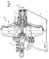
- Fig. 1
- zeigt einen elektronisch gesteuerten Bremskraftverstärker einer Fahrzeugbremsanlage gemäß der Erfindung in einer schematischen Schnittansicht.
- Fig. 2
- zeigt ein Diagramm mit dem Druckverlauf in der hydraulischen Bremsanlage in Abhängigkeit von der Bremspedalbetätigungskraft bei einer automatischen Bremsung.
- Fig. 1
- shows an electronically controlled brake booster of a vehicle brake system according to the invention in a schematic sectional view.
- Fig. 2
- shows a diagram with the pressure curve in the hydraulic brake system as a function of the brake pedal actuation force during automatic braking.
In Fig. 1 ist ein Bremskraftverstärker einer Fahrzeugbremsanlage im Überblick veranschaulicht. Der dargestellte Bremskraftverstärker 10 hat ein im wesentlichen rotationssymmetrisches Gehäuse 12, in dem eine hintere Kammer 14 sowie eine vordere Kammer 16 angeordnet und durch eine bewegliche Wand 18 voneinander getrennt sind. Zu dem Bremskraftverstärker 10 gehört eine Steuerventilanordnung 20, das mit der beweglichen Wand 18 zu gemeinsamer Relativbewegung in Bezug auf das Gehäuse 12 verbunden ist. Auf das Ventil wirkt das vordere Ende eines stangenförmigen Betätigungsgliedes 22, das im Einbauzustand mit einem (nicht gezeigten) Bremspedal des Kraftfahrzeuges verbunden ist.An overview of a brake booster of a vehicle brake system is illustrated in FIG. 1. The
Innerhalb des Bremskraftverstärkers 10 ist ein Kraftabgabeglied 30 angeordnet, das sich an der Steuerventilanordnung 20 abstützt. Das Kraftabgabeglied 30 ist zur Betätigung eines Hauptbremszylinders 32 vorgesehen.A
In dem abgebildeten Ruhezustand, bei abgeschalteter Unterdruckquelle, herrscht in den beiden Kammern 14 und 16 Atmosphärendruck. Bei eingeschalteter Unterdruckquelle, also beispielsweise bei laufendem Motor, mit dessen Ansaugrohr die vordere Kammer 16 verbunden ist, entsteht in der vorderen Kammer 16 ein Unterdruck, so daß die bewegliche Wand 18, und mit ihr das Ventil, geringfügig nach vorne verschoben wird. Dadurch stellt sich ein erneutes Druckgleichgewicht zwischen den beiden Kammern 14 und 16 ein. Von dieser Bereitschaftsstellung aus ist eine verlustwegfreie Betätigung des Bremskraftverstärkers 10 gewährleistet.In the idle state shown, with the vacuum source switched off, atmospheric pressure prevails in the two
Bei einer normalen Bremsbetätigung durch den Fahrer arbeitet der Bremskraftverstärker 10 in üblicher Weise, indem die Verbindung zwischen den beiden Kammern 14 und 16 über das Ventil unterbrochen wird und Umgebungsluft in die hintere Kammer 14 strömt. Infolgedessen steht eine durch den Bremskraftverstärker 10 verstärkte Betätigungskraft am Kraftabgabeglied 30 zur Verfügung.In the case of a normal brake actuation by the driver, the
Die Steuerventilanordnung 20 kann durch einen Elektormagneten 24 in einer Weise betätigt werden, daß die Steuerventilanordnung 20 entweder nur durch den Elektromagneten 24 aktiviert wird, oder zusätzlich zu einer Betätigung durch das Bremspedal über das Betätigungsglied 22. Dazu ist der Elektromagnet 24 über die Leitung 26 mit der elektronischen Steuereinrichtung ECU verbunden. An dem Betätigungsglied 22 ist ein Kraftsensor 28 vorgesehen, der über eine Leitung 29 ebenfalls mit der elektronischen Steuereinrichtung verbunden ist.The
Der Kraftsensor 28 kann als Dehnungs-Meßstreifen oder als Drucksensor realisiert sein.The
Dabei ist entscheidend, daß der Kraftsensor 28 an einer Stelle angeordnet ist, an der die gemessene Kraft (und deren zeitlicher Verlauf) noch möglichst genau mit der Kraft übereinstimmt, die der Fahrer auf das (nicht gezeigte) Bremspedal 10 ausübt. Das heißt, daß eine mehrfache Umlenkung, Übersetzung etc. der Kraft vor ihrer Messung zu vermeiden ist.The decisive factor here is that the
Als Kraftsensor ist z.B. ein Sensor verwendbar wie er in der P 43 00 995.6 beschrieben ist. Wenn der Fahrer das Bremspedal mit einer bestimmten Kraftanstiegsgeschwindigkeit oder mit einer bestimmten Bremspedalbetätigungsgeschwindigkeit betätigt, wird dies von der elektronischen Steuereinrichtung ECU (z.B. durch den Kraftsensor 28) erfaßt und ein Auslösesignal über die Leitung 26 an den Elektromagneten 24 geschickt. Dieses Signal bewirkt eine Verschiebung der Steuerventilanordnung 20, so daß Umgebungsluft in die Kammer 14 einströmen kann. Dies hat zur Folge, daß die bewegliche Wand 18 sich im Sinne einer Verkleinerung des Volumens der Kammer 16 bewegt und dabei das Kraftabgabeglied 30 in Richtung des Pfeiles P verschiebt. Die dabei auf den Hauptbremszylinder 32 ausgeübte Betätigungskraft ist unabhängig von der momentan noch auf das Bremspedal bzw. das Betätigungsglied 22 wirkenden Kraft. Vielmehr bewirkt die Betätigung des Elektromagneten 24 eine ungehinderte und schnelle Betätigung der Fahrzeugbremsen mit dem maximal möglichen Hydraulikdruck.The force sensor is e.g. a sensor can be used as described in P 43 00 995.6. When the driver operates the brake pedal at a certain rate of force increase or at a certain rate of brake pedal actuation, this is sensed by the electronic control device ECU (e.g. by the force sensor 28) and a trigger signal is sent via
In Fig. 2 ist ein Verlauf eines Bremsvorganges mit einer automatischen Bremsung veranschaulicht. Ausgehend von dem Punkt 1 in Fig. 2 bewirkt sowohl die auf das Betätigungsglied 22 (vom Fahrer ausgeübte) Kraft, als auch die durch den Bremskraftverstärker 10 hervorgegangene Kraftverstärkung den steilen Druckanstieg des Drucks p in den Hydraulikleitungen zu den Fahrzeugbremsen. Die maximal mögliche durch den Bremskraftverstärker 10 bewirkbare Druckbeaufschlagung wird in dem mit 2 bezeichneten Punkt in Fig. 2 erreicht. Ein weiterer Anstieg (bis zu dem Punkt 3) ist nur noch durch ein weiteres Betätigen des Bremspedals möglich, wobei nur die vom Fahrer ausgeübte Kraft noch einen Anstieg des Drucks p bewirkt. Der Bremskraftverstärker leistet hierzu keinen weiteren Beitrag mehr.A course of a braking operation with automatic braking is illustrated in FIG. 2. Starting from
Die erfindungsgemäße Betätigung der elektronisch gesteuerten Fahrzeugbremsanlage ist wie folgt:The actuation of the electronically controlled vehicle brake system according to the invention is as follows:
Am Anfang einer Betätigung des Bremspedals (Punkt 1 in Fig. 2) steigt der Druck in der hydraulischen Bremsanlage relativ steil an, da die vom Fahrer auf das Bremspedal ausgeübte Kraft durch den Bremskraftverstärker 10 linear vestärkt wird. Beim Erreichen des Punktes 4 in Fig. 2 aktiviert die elektronische Steuerung ECU über die Leitung 26 den Elektromagneten 24, so daß der Bremskraftverstärker automatisch zur Ausführung einer Notbremsung betätigt wird, was in einem praktisch senkrechten Anstieg des Drucks in der hydraulischen Bremsanlage bis auf den Punkt 5 in Fig. 2 zur Folge hat. Der Fahrer hat in Punkt 5 zwei Möglichkeiten. Entweder er erhöht die Kraft auf das Bremspedal weiter, in diesem Fall würde der Druck in der hydraulischen Bremsanlage sich in Richtung auf den Punkt 2 in Fig. 1 entlang der gestrichelten Verbindungslinie zwischen dem Punkt 5 und dem Punkt 2 erhöhen. Wenn jedoch der Fahrer einen Abbruch der Notbremsung erreichen will, muß er die auf das Bremspedal wirkende Kraft um den Betrag dF verringern. Dies hat auch zur Folge, daß sich der Druck in der hydraulischen Bremsanlage auf den Punkt 6 in Fig. 2 reduziert. Sobald der zu dem Punkt 6 gehörige Wert der auf das Bremspedal ausgeübten Kraft erreicht ist, wird dies durch die elektronische Steuerung ECU mittels des Kraftsensors 28 erfaßt und eine Deaktivierung des Elektromagneten 24 ausgelöst. Dies bewirkt eine Rücknahme der Notbremsung und eine Rückführung des Bremsdrucks auf die normale Bremskraftverstärkungskennlinie (Punkt 1 in Fig. 2) entlang der gestrichelten Linie zwischen Punkt 6 und Punkt 1 in Fig. 2.At the beginning of an actuation of the brake pedal (
Das zur Auslösung der automatischen Bremsung zu füllende Kritierium ist das Erreichen des Punktes 4 bzw. der dazugehörige Kraftwert K. Wenn die Pedalbetätigungskraft um einen vorbestimmten Wert dF verringert wird bzw. wenn ein unmittelbar vor der Auslösung der automatischen (Not-)Brem-sung erfaßter auf das Bremspedal wirkender Kraftwert wieder gemessen wird (Punkt 6 in Fig. 2) erfolgt die Rücknahme der Notbremsung durch Entregung des Elektromagneten 24. Die Rückführung des Bremskraftverstärkers auf die normale Verstärkerkennlinie (Punkte 1-2-3) kann unterschiedlich schnell oder in Abhängigkeit von Umgebungskriterien (Fahrzeugverzögerung, Fahrzeuggeschwindigkeit oder dergl.) erfolgen.The criterion to be triggered for triggering the automatic braking is reaching point 4 or the associated force value K. If the pedal actuation force is reduced by a predetermined value dF or if one is detected immediately before the automatic (emergency) braking is triggered force value acting on the brake pedal is measured again (
Claims (14)
Applications Claiming Priority (2)
| Application Number | Priority Date | Filing Date | Title |
|---|---|---|---|
| DE4436819 | 1994-10-14 | ||
| DE4436819A DE4436819C2 (en) | 1994-10-14 | 1994-10-14 | Electronically controlled vehicle brake system and method for its operation |
Publications (2)
| Publication Number | Publication Date |
|---|---|
| EP0711695A2 true EP0711695A2 (en) | 1996-05-15 |
| EP0711695A3 EP0711695A3 (en) | 1998-01-07 |
Family
ID=6530816
Family Applications (1)
| Application Number | Title | Priority Date | Filing Date |
|---|---|---|---|
| EP95114808A Withdrawn EP0711695A3 (en) | 1994-10-14 | 1995-09-20 | System and operating procedure of an electronically controlled vehicle brake |
Country Status (6)
| Country | Link |
|---|---|
| US (1) | US5590937A (en) |
| EP (1) | EP0711695A3 (en) |
| JP (1) | JPH08207747A (en) |
| KR (1) | KR960013887A (en) |
| BR (1) | BR9504370A (en) |
| DE (1) | DE4436819C2 (en) |
Cited By (17)
| Publication number | Priority date | Publication date | Assignee | Title |
|---|---|---|---|---|
| US6027182A (en) * | 1997-07-08 | 2000-02-22 | Toyota Jidosha Kabushiki Kaisha | Brake force control apparatus for properly performing both an ABS function and a BA function |
| US6120110A (en) * | 1996-04-23 | 2000-09-19 | Toyota Jidosha Kabushiki Kaisha | Brake force control device |
| US6129423A (en) * | 1996-04-25 | 2000-10-10 | Toyota Jidosha Kabushiki Kaisha | Brake force control apparatus |
| US6170924B1 (en) | 1997-07-08 | 2001-01-09 | Toyota Jidosha Kabushiki Kaisha | Brake force control apparatus accurately detecting an amount of brake operation intended by a vehicle operator |
| US6189987B1 (en) | 1996-04-26 | 2001-02-20 | Toyota Jidosha Kabushiki Kaisha | Brake force control apparatus |
| US6189986B1 (en) | 1996-04-26 | 2001-02-20 | Toyota Jidosha Kabushiki Kaisha | Braking force control apparatus |
| US6199963B1 (en) | 1996-04-30 | 2001-03-13 | Toyota Jidosha Kabushiki Kaisha | Braking force control apparatus |
| US6217133B1 (en) | 1997-05-09 | 2001-04-17 | Toyota Jidosha Kabushiki Kaisha | Brake force control apparatus |
| US6227629B1 (en) | 1996-04-05 | 2001-05-08 | Toyota Jidosha Kabushiki Kaisha | Brake force control apparatus |
| US6234589B1 (en) | 1996-05-28 | 2001-05-22 | Toyota Jidosha Kabushiki Kaisha | Braking force control apparatus |
| US6280008B1 (en) | 1996-04-26 | 2001-08-28 | Toyota Jidosha Kabushiki Kaisha | Brake force control apparatus |
| US6283561B1 (en) | 1997-03-06 | 2001-09-04 | Toyota Jidosha Kabushiki Kaisha | Braking force controller |
| US6293633B1 (en) | 1996-08-02 | 2001-09-25 | Toyota Jidosha Kabushiki Kaisha | Braking force control apparatus |
| US6312064B1 (en) | 1997-03-06 | 2001-11-06 | Toyota Jidosha Kabushiki Kaisha | Braking force controller |
| US6322168B1 (en) | 1996-04-26 | 2001-11-27 | Toyota Jidosha Kabushiki Kaisha | Braking force control apparatus |
| US6409288B2 (en) | 1996-04-26 | 2002-06-25 | Toyota Jidosha Kabushiki Kaisha | Braking force controlling apparatus |
| US6460942B1 (en) | 1996-04-23 | 2002-10-08 | Toyota Jidosha Kabushiki Kaisha | Braking force controller |
Families Citing this family (20)
| Publication number | Priority date | Publication date | Assignee | Title |
|---|---|---|---|---|
| DE4410769C2 (en) * | 1994-03-28 | 1998-04-09 | Lucas Ind Plc | Valve assembly for controlling a vacuum brake booster with an electromagnetic actuator |
| DE4440290C1 (en) * | 1994-11-11 | 1995-12-07 | Daimler Benz Ag | Release threshold determination system for vehicle automatic braking |
| DE4441910C2 (en) * | 1994-11-24 | 1998-11-12 | Lucas Ind Plc | Electronically controlled brake booster |
| DE4441913C2 (en) * | 1994-11-24 | 1998-11-12 | Lucas Ind Plc | Electronically controlled brake booster |
| JP3811972B2 (en) * | 1995-10-30 | 2006-08-23 | アイシン精機株式会社 | Brake fluid pressure control device for automobiles |
| DE19540397C1 (en) * | 1995-10-30 | 1997-04-10 | Daimler Benz Ag | Method for determining a trigger threshold for an automatic braking process |
| DE19612952C2 (en) * | 1996-04-01 | 2001-07-12 | Lucas Ind Plc | Electronically controlled brake booster |
| DE19632278C2 (en) * | 1996-08-09 | 2002-05-08 | Lucas Ind Plc | Electronically controlled brake booster and method for adjusting it |
| DE19641889C1 (en) * | 1996-10-10 | 1998-04-23 | Lucas Ind Plc | Brake booster with electromagnetic actuation unit |
| JP4026092B2 (en) * | 1997-09-30 | 2007-12-26 | 株式会社日立製作所 | Braking device |
| DE19750383C1 (en) * | 1997-11-13 | 1998-12-24 | Lucas Ind Plc | Pneumatic brake booster for motor vehicle |
| JPWO2004031009A1 (en) * | 2002-10-04 | 2006-02-02 | 株式会社アドヴィックス | Emergency braking device for vehicles |
| DE102006039121A1 (en) * | 2006-04-03 | 2007-10-04 | Robert Bosch Gmbh | Safety-deactivating method for deactivating an activated safety function in a motor vehicle relies on a braking process carried out by a driver |
| DE102009057836B4 (en) * | 2009-12-10 | 2013-02-21 | Continental Teves Ag & Co. Ohg | Emergency braking assistance system to assist a driver of a vehicle when starting |
| US8423256B2 (en) * | 2009-12-23 | 2013-04-16 | Goodrich Corporation | Systems and methods for adaptive deceleration |
| DE102010001355A1 (en) * | 2010-01-29 | 2011-08-04 | Robert Bosch GmbH, 70469 | Vacuum-brake booster for brake system of motor vehicle for loading master cylinder with supporting force, has adjusting unit for adjusting supporting force and main control valve for adjusting supporting force |
| JP2013517982A (en) * | 2010-01-29 | 2013-05-20 | ロベルト・ボッシュ・ゲゼルシャフト・ミト・ベシュレンクテル・ハフツング | Controllable pneumatic brake booster and its operating method |
| JP7092085B2 (en) * | 2019-04-03 | 2022-06-28 | トヨタ自動車株式会社 | Vehicle braking device |
| DE112020002307T5 (en) | 2019-05-09 | 2022-02-17 | Cts Corporation | VEHICLE BRAKE PEDAL WITH PEDAL RESISTANCE ASSEMBLY AND FORCE/POSITION SENSOR |
| CN110239497A (en) * | 2019-07-02 | 2019-09-17 | 平阳星嘉智能科技有限公司 | Electrically controlled brake system and preparatory emergency braking system |
Citations (2)
| Publication number | Priority date | Publication date | Assignee | Title |
|---|---|---|---|---|
| DE4028290C1 (en) | 1990-09-06 | 1992-01-02 | Daimler-Benz Aktiengesellschaft, 7000 Stuttgart, De | |
| DE4102496A1 (en) | 1991-01-29 | 1992-02-20 | Daimler Benz Ag | Brake pressure control unit for motor vehicle - couples pressures proportional to braking unit pedal force with ABS for dynamic stable behaviour |
Family Cites Families (15)
| Publication number | Priority date | Publication date | Assignee | Title |
|---|---|---|---|---|
| GB2089453B (en) * | 1980-11-04 | 1984-11-28 | Honda Motor Co Ltd | Automatic braking system for vehicles |
| JPS6237261A (en) * | 1985-08-13 | 1987-02-18 | Jidosha Kiki Co Ltd | Input detecting device for booster |
| GB8901066D0 (en) * | 1989-01-18 | 1989-03-15 | Lucas Ind Plc | Improvements in fluidpressure operated boosters for vehicle braking systems |
| JP2709163B2 (en) * | 1989-11-20 | 1998-02-04 | 住友電気工業株式会社 | Brake system |
| DE9110739U1 (en) * | 1990-09-06 | 1991-10-24 | Daimler-Benz Aktiengesellschaft, 7000 Stuttgart, De | |
| DE4208496C1 (en) * | 1992-03-17 | 1993-08-05 | Mercedes-Benz Aktiengesellschaft, 7000 Stuttgart, De | |
| DE4217409C2 (en) * | 1992-05-26 | 1996-03-21 | Lucas Ind Plc | Method for regulating a brake pressure with a brake booster |
| JPH0672297A (en) * | 1992-08-25 | 1994-03-15 | Fuji Heavy Ind Ltd | Control method of automatic brake device |
| DE4234043C1 (en) * | 1992-10-09 | 1994-03-24 | Daimler Benz Ag | Brake pressure control device for a road vehicle |
| DE4242887A1 (en) * | 1992-12-18 | 1994-06-23 | Wabco Westinghouse Fahrzeug | Brake system with at least one brake |
| DE4300995C2 (en) * | 1993-01-15 | 1994-10-27 | Lucas Ind Plc | Force sensor and method for its manufacture |
| DE4309850C2 (en) * | 1993-03-26 | 1996-12-12 | Lucas Ind Plc | Brake booster system for regulating a brake pressure with a brake booster |
| DE4325940C1 (en) * | 1993-08-03 | 1994-12-01 | Daimler Benz Ag | Method for determining the start and end of an automatic braking process |
| DE4338066C1 (en) * | 1993-11-08 | 1995-04-06 | Daimler Benz Ag | Method for performing an automatic braking process for motor vehicles with an anti-lock braking system |
| DE4405076C2 (en) * | 1994-02-17 | 1997-01-02 | Lucas Ind Plc | Pneumatic brake booster with electromagnetic auxiliary control, in particular for motor vehicle brake systems |
-
1994
- 1994-10-14 DE DE4436819A patent/DE4436819C2/en not_active Expired - Fee Related
-
1995
- 1995-09-20 EP EP95114808A patent/EP0711695A3/en not_active Withdrawn
- 1995-09-25 US US08/533,011 patent/US5590937A/en not_active Expired - Fee Related
- 1995-10-11 BR BR9504370A patent/BR9504370A/en not_active Application Discontinuation
- 1995-10-13 JP JP7291942A patent/JPH08207747A/en active Pending
- 1995-10-13 KR KR1019950035389A patent/KR960013887A/en not_active Application Discontinuation
Patent Citations (2)
| Publication number | Priority date | Publication date | Assignee | Title |
|---|---|---|---|---|
| DE4028290C1 (en) | 1990-09-06 | 1992-01-02 | Daimler-Benz Aktiengesellschaft, 7000 Stuttgart, De | |
| DE4102496A1 (en) | 1991-01-29 | 1992-02-20 | Daimler Benz Ag | Brake pressure control unit for motor vehicle - couples pressures proportional to braking unit pedal force with ABS for dynamic stable behaviour |
Cited By (17)
| Publication number | Priority date | Publication date | Assignee | Title |
|---|---|---|---|---|
| US6227629B1 (en) | 1996-04-05 | 2001-05-08 | Toyota Jidosha Kabushiki Kaisha | Brake force control apparatus |
| US6120110A (en) * | 1996-04-23 | 2000-09-19 | Toyota Jidosha Kabushiki Kaisha | Brake force control device |
| US6460942B1 (en) | 1996-04-23 | 2002-10-08 | Toyota Jidosha Kabushiki Kaisha | Braking force controller |
| US6129423A (en) * | 1996-04-25 | 2000-10-10 | Toyota Jidosha Kabushiki Kaisha | Brake force control apparatus |
| US6189987B1 (en) | 1996-04-26 | 2001-02-20 | Toyota Jidosha Kabushiki Kaisha | Brake force control apparatus |
| US6189986B1 (en) | 1996-04-26 | 2001-02-20 | Toyota Jidosha Kabushiki Kaisha | Braking force control apparatus |
| US6280008B1 (en) | 1996-04-26 | 2001-08-28 | Toyota Jidosha Kabushiki Kaisha | Brake force control apparatus |
| US6322168B1 (en) | 1996-04-26 | 2001-11-27 | Toyota Jidosha Kabushiki Kaisha | Braking force control apparatus |
| US6409288B2 (en) | 1996-04-26 | 2002-06-25 | Toyota Jidosha Kabushiki Kaisha | Braking force controlling apparatus |
| US6199963B1 (en) | 1996-04-30 | 2001-03-13 | Toyota Jidosha Kabushiki Kaisha | Braking force control apparatus |
| US6234589B1 (en) | 1996-05-28 | 2001-05-22 | Toyota Jidosha Kabushiki Kaisha | Braking force control apparatus |
| US6293633B1 (en) | 1996-08-02 | 2001-09-25 | Toyota Jidosha Kabushiki Kaisha | Braking force control apparatus |
| US6283561B1 (en) | 1997-03-06 | 2001-09-04 | Toyota Jidosha Kabushiki Kaisha | Braking force controller |
| US6312064B1 (en) | 1997-03-06 | 2001-11-06 | Toyota Jidosha Kabushiki Kaisha | Braking force controller |
| US6217133B1 (en) | 1997-05-09 | 2001-04-17 | Toyota Jidosha Kabushiki Kaisha | Brake force control apparatus |
| US6027182A (en) * | 1997-07-08 | 2000-02-22 | Toyota Jidosha Kabushiki Kaisha | Brake force control apparatus for properly performing both an ABS function and a BA function |
| US6170924B1 (en) | 1997-07-08 | 2001-01-09 | Toyota Jidosha Kabushiki Kaisha | Brake force control apparatus accurately detecting an amount of brake operation intended by a vehicle operator |
Also Published As
| Publication number | Publication date |
|---|---|
| DE4436819A1 (en) | 1996-04-18 |
| US5590937A (en) | 1997-01-07 |
| DE4436819C2 (en) | 1998-09-24 |
| BR9504370A (en) | 1997-04-08 |
| KR960013887A (en) | 1996-05-22 |
| JPH08207747A (en) | 1996-08-13 |
| EP0711695A3 (en) | 1998-01-07 |
Similar Documents
| Publication | Publication Date | Title |
|---|---|---|
| EP0711695A2 (en) | System and operating procedure of an electronically controlled vehicle brake | |
| DE4309850C2 (en) | Brake booster system for regulating a brake pressure with a brake booster | |
| DE4436297C2 (en) | Electronically controlled brake booster and method for its operation | |
| EP0435113B1 (en) | Vehicle brake installation | |
| EP0867350B1 (en) | Brake control system for vehicles | |
| EP0817736B1 (en) | Motor vehicle hydraulic braking system | |
| DE19620540C2 (en) | Electronically controllable brake system | |
| DE4102496A1 (en) | Brake pressure control unit for motor vehicle - couples pressures proportional to braking unit pedal force with ABS for dynamic stable behaviour | |
| DE4324205A1 (en) | Brake system for motor vehicles | |
| EP0365629B1 (en) | Braking pressure regulating system | |
| WO1999019194A1 (en) | Preventing the collision of a vehicle with an obstacle | |
| EP1021327B1 (en) | Automobile brake system | |
| DE19631862B4 (en) | braking device | |
| DE19731962C2 (en) | Fully hydraulic brake booster / master cylinder unit | |
| EP2296948B1 (en) | Brake booster for an automotive brake system and corresponding automotive brake system | |
| DE19845052A1 (en) | Vehicle brake system with brake support mechanism | |
| EP2688782A1 (en) | Method and system for compensating for an insufficient pressure build-up in the brake system of a vehicle | |
| DE10154633A1 (en) | Method and appliance for controlling at least one vehicle wheel brake system, controls brake pedal decay according to speed of withdrawal of brake pedal | |
| DE19750383C1 (en) | Pneumatic brake booster for motor vehicle | |
| DE3814404A1 (en) | Brake system with antilock and traction control for motor vehicles | |
| EP1053156B1 (en) | Brake power booster and a method for controlling the same | |
| DE19841879A1 (en) | Brake booster and method for its control | |
| EP0199352A1 (en) | Braking power booster for a hydraulic braking system of a motor vehicle | |
| DE102007016867A1 (en) | Brake booster for vehicle, has transfer device implemented as lever arrangement, where brake pedal is mechanically decoupled by piston of main brake cylinder during mode of operation | |
| DE2308979A1 (en) | BRAKING SYSTEM FOR A VEHICLE, IN PARTICULAR A MOTOR VEHICLE |
Legal Events
| Date | Code | Title | Description |
|---|---|---|---|
| PUAI | Public reference made under article 153(3) epc to a published international application that has entered the european phase |
Free format text: ORIGINAL CODE: 0009012 |
|
| AK | Designated contracting states |
Kind code of ref document: A2 Designated state(s): DE ES FR GB IT |
|
| PUAL | Search report despatched |
Free format text: ORIGINAL CODE: 0009013 |
|
| AK | Designated contracting states |
Kind code of ref document: A3 Designated state(s): DE ES FR GB IT |
|
| 17P | Request for examination filed |
Effective date: 19980120 |
|
| 17Q | First examination report despatched |
Effective date: 19991210 |
|
| RAP1 | Party data changed (applicant data changed or rights of an application transferred) |
Owner name: LUCAS INDUSTRIES LIMITED |
|
| STAA | Information on the status of an ep patent application or granted ep patent |
Free format text: STATUS: THE APPLICATION IS DEEMED TO BE WITHDRAWN |
|
| 18D | Application deemed to be withdrawn |
Effective date: 20000331 |