EP0711537B1 - Incubator mattress tilt mechanism - Google Patents
Incubator mattress tilt mechanism Download PDFInfo
- Publication number
- EP0711537B1 EP0711537B1 EP95307821A EP95307821A EP0711537B1 EP 0711537 B1 EP0711537 B1 EP 0711537B1 EP 95307821 A EP95307821 A EP 95307821A EP 95307821 A EP95307821 A EP 95307821A EP 0711537 B1 EP0711537 B1 EP 0711537B1
- Authority
- EP
- European Patent Office
- Prior art keywords
- incubator
- infant
- bed
- tilt mechanism
- bent rod
- Prior art date
- Legal status (The legal status is an assumption and is not a legal conclusion. Google has not performed a legal analysis and makes no representation as to the accuracy of the status listed.)
- Expired - Lifetime
Links
Images


Classifications
-
- A—HUMAN NECESSITIES
- A61—MEDICAL OR VETERINARY SCIENCE; HYGIENE
- A61G—TRANSPORT, PERSONAL CONVEYANCES OR ACCOMMODATION SPECIALLY ADAPTED FOR PATIENTS OR DISABLED PERSONS; OPERATING TABLES OR CHAIRS; CHAIRS FOR DENTISTRY; FUNERAL DEVICES
- A61G11/00—Baby-incubators; Couveuses
-
- A—HUMAN NECESSITIES
- A61—MEDICAL OR VETERINARY SCIENCE; HYGIENE
- A61G—TRANSPORT, PERSONAL CONVEYANCES OR ACCOMMODATION SPECIALLY ADAPTED FOR PATIENTS OR DISABLED PERSONS; OPERATING TABLES OR CHAIRS; CHAIRS FOR DENTISTRY; FUNERAL DEVICES
- A61G11/00—Baby-incubators; Couveuses
- A61G11/001—Baby-incubators; Couveuses with height-adjustable elements
- A61G11/002—Baby-incubators; Couveuses with height-adjustable elements height-adjustable patient support
-
- A—HUMAN NECESSITIES
- A61—MEDICAL OR VETERINARY SCIENCE; HYGIENE
- A61G—TRANSPORT, PERSONAL CONVEYANCES OR ACCOMMODATION SPECIALLY ADAPTED FOR PATIENTS OR DISABLED PERSONS; OPERATING TABLES OR CHAIRS; CHAIRS FOR DENTISTRY; FUNERAL DEVICES
- A61G11/00—Baby-incubators; Couveuses
- A61G11/008—Baby-incubators; Couveuses tiltable about a horizontal axis, e.g. oscillating
-
- A—HUMAN NECESSITIES
- A61—MEDICAL OR VETERINARY SCIENCE; HYGIENE
- A61G—TRANSPORT, PERSONAL CONVEYANCES OR ACCOMMODATION SPECIALLY ADAPTED FOR PATIENTS OR DISABLED PERSONS; OPERATING TABLES OR CHAIRS; CHAIRS FOR DENTISTRY; FUNERAL DEVICES
- A61G7/00—Beds specially adapted for nursing; Devices for lifting patients or disabled persons
- A61G7/002—Beds specially adapted for nursing; Devices for lifting patients or disabled persons having adjustable mattress frame
- A61G7/005—Beds specially adapted for nursing; Devices for lifting patients or disabled persons having adjustable mattress frame tiltable around transverse horizontal axis, e.g. for Trendelenburg position
Definitions
- This invention relates to infant incubators, and more particularly, to a means of setting and adjusting the tilt angle of an infant bed located within an infant incubator.
- Infant incubators have a variety of ways of adjusting the angle of tilt of infant beds within the apparatus. It is preferable that the tilting mechanism be operable from external of the infant incubator so that the attending personnel do not have to open any doors or portholes to carry out the process of adjusting the tilt angle.
- the tilt angle be movable continuously or infinitely variable over a wide latitude of positions, both to raise and lower the infant head or feet and not be constrained to two or three preset conditions.
- the tilt mechanism should be self sustaining, that is, once the level has been selected, it is preferable that the user merely release the control and have the selected position automatically stabilize at that position.
- the change in tilt angle must be relatively smooth and easy to operate without any abrupt movements so that the infant is not disturbed and is not startled in changing the tilt angle.
- a current tilt mechanism is exemplified in U.S. Patent 4,734,945, which discloses all the features of the preamble of claim 1, and where a pair of selector handles rotate a pair of bent rods that raise and lower the infant position. As indicated, however, the position to be selected is limited to only a few selected positions and the operator cannot place the infant at any position intermediate the set positions made available by the manufacturer.
- a further difficulty with the scissors mechanism of the aforementioned U.S. Patent reside in the mechanism having relatively fine threads located within the infant compartment to operate the scissors. Not only do the fine threads require considerable rotations of the handle (18-20) to move the infant bed from one extreme position to the other, but the mechanism and the fine threads are subject to frequent contamination and are extremely difficult to clean. Thus the mechanism must be cleaned frequently and that cleaning is burdensome and inconvenient to the medical personnel.
- a tilt mechanism for adjusting the angular position of an infant bed adapted to underlie an infant contained within an infant incubator comprises: at least one bent rod contained within the infant incubator and having one free end thereof, the bent rod having an offset portion located beneath the infant bed, said offset portion being adapted to move said bed upwardly or downwardly as said one free end thereof is rotated about an axis of rotation, a lead screw affixed to the exterior of the incubator and being rotatable along a fixed axis of rotation with respect to the incubator, linkage means affixed to the incubator and adapted to translate the rotation of said lead screw to cause corresponding rotation of said one free end of said bent rod to thereby raise or lower the infant bed to a desired position.
- a plurality of bent rods having a axis of rotation underlie the infant bed and which are secured to the incubator and are rotatable about that axis.
- a bed lifter is also used and in turn is moved by the rotational movement of the bent rods.
- Rotation of the bent rods about their axis of rotation is accomplished by a lever arm that is affixed to an end of the bent rod external of the incubator. That lever arm is joined by a linkage to a lead screw that is rotatable affixed to the infant incubator and which, when rotated by the user operating a large hand knob, causes lateral movement of the linkage. That lateral movement is translated into rotational movement of the bent rod through the lever arm and thus, by rotating the lead screw, the infant bed can readily be elevated or reclined.
- the lead screw includes a large hand knob located alongside of the incubator and free from hindering the operation of the front door or in any way impeding the access to the infant.
- the rotational movement is, by means of a linkage, translated into rotational movement of the bent rod having an axis of rotation 90 degrees displaced from the axis of rotation of the hand knob.
- the pitch of the lead screw By selecting the pitch of the lead screw, the number of turns is easily determined to move the infant bed between its extreme positions and can readily be a lesser number than the turns needed to operate the scissors mechanism cited earlier and thus more convenient to the user.
- the lead screw and substantially all of the components that operate the tilt system are located outside the infant compartment and thus are not subject to contamination. The entire mechanism is readily disassembled, however, for cleaning in a convenient and easy manner.
- a tilt mechanism constructed in accordance with the present invention is located at both ends of the incubator and therefore, the same mechanism, albeit mirror images, can be used to raise and/or lower either side of the infant bed.
- FIG 1 there is shown an isometric view of an incubator 10 having incorporated therein, the tilt mechanism of the present invention. Parts of the infant incubator 10 have been omitted, however, the incubator itself is more specifically shown and described in U.S. Patent 4, 936,824 of Koch et al.
- the incubator 10 shown in Figure 1 includes a base 12 made of a structural plastics material and which contains the equipment and controls necessary for a functioning incubator.
- a hood 14 sits atop the base 12 of incubator 10 and is generally comprised of a transparent material so that attending personnel can easily view the infant contained within the incubator 10.
- the hood 14 also generally includes a front door, hand holes and the like for access to the infant.
- an infant bed 16 which is positioned beneath the transparent hood 14 and rests upon the base 12.
- the infant bed 16 is used to support the infant and includes a mattress to underlie that infant.
- the infant bed 16 is shown, partially cut-away, in Figure 1 so that the functioning parts of the tilt mechanism can be more readily viewed.
- the infant bed 16 be tiltable to various angles desired by the attending personnel. In certain applications, it is sometimes desirable to raise the level of the head of the infant and at other times the feet of the infant. As described in the present application, however, only one tilt mechanism will be presented, it being obvious that there will normally be a tilt mechanism at both ends of the infant bed 16, one being the mirror image of the other and therefore the description of but one of the tilt mechanisms is sufficient.
- a recessed area 18 is formed in the base 12 and as will become apparent, the recessed area 18 receives various of the components of the tilt mechanism so that the infant bed 16 can be brought to a position level with the upper surface of the base 12 and the components are contained beneath the infant bed 16 within the recessed area 18.
- a bed lifter 20 is rotatably affixed to the base 12 within the recessed area 18 and is rotatable about a pair of pivot points 22 formed therein.
- the specific details of the pivot points 22 will be later explained in connection with the details of the assembly and disassembly of the tilt mechanism for incubator 10.
- Bed lifter 20 has its other free end 24 positioned so as to support the infant bed 16 when it is raised or lowered with respect to base 12 and can be seen as engaging the infant bed 16.
- Bed lifter 20 also includes a pair of elongated slots 26, (only one of which is shown in Figure 1) the purpose of which will become apparent.
- a bent rod 28 is located beneath the infant bed 16 and includes an offset portion 30 that extends upwardly, at times, toward the infant bed 16. Bent rod 28 is also rotatably mounted to the base 12 and is rotatable about pivot points 32 (only one of which is shown in Figure 1) that together form an axis of rotation for the bent rod 28.
- the bent rod 28 passes through each of the elongated slots 26 of bed lifter 20 such that the bed lifter 20 is raised or lowered as the bent rod 28 is raised or lowered.
- FIG 2 in conjunction with Figure 1, there is shown an isometric view, partially broken away, showing further details of the tilt mechanism constructed in accordance with the present invention.
- the rotational movement of bent rod 28 also causes the movement of the bed lifter 20 in the directions of double arrow A.
- bent rod 28 extends external of the incubator 10 and is coupled to a interface or key 34.
- the means of coupling the external end of bent rod 28 to the key 34 will be further explained later with reference to the means of disassembling and assembling the tilt mechanism.
- the external end of the bent rod 28 is, during operation, affixed to the key 34 and rotational motion of the bent rod 28 is transmitted directly to the key 34 and vice versa.
- the outer end of the key 34 is a square end 36, however any variety of keying arrangement may be used to connect the key 34 to a lever arm 38.
- a similar shaped hole 40 in the lever arm 38 causes the lever arm 38 and key 34 to rotate together.
- a link 42 is, in turn, connected to the lever arm 38 at a junction point 44 that is offset a predetermined distance from the axis of rotation of the bent rod 28, that is, since the center of rotation of the key 34 is coaxial with the axis of rotation of the bent rod 28, the junction point 44 is thereby displaced that predetermined distance from the axis of rotation of key 34 as well as of lever arm 38.
- a lead screw slide 46 is affixed at a junction point 48 to the other end of the link 42.
- Lead screw slide 46 has internal threads of known pitch and dimensions and slides along a lead screw slide bearing 50 formed within the cover 52.
- the lead screw slide bearing 50 allows the lead screw slide 46 to move laterally with respect to the incubator 10 but constrains the lead screw slide 46 from rotational movement. Lateral movement of lead screw slide 46 and, of course, link 42 is shown by the double arrow B.
- Threadedly engaged to the lead screw slide 46 is a lead screw 54 having, obviously, external threads that are compatible to and threadedly engaged with the internal threads within the lead screw slide 46.
- the lead screw 54 is held within a lead screw bearing 56 and is thus allowed to rotate but lateral movement is constrained.
- a hand knob 58 of a relatively large size to make gripping by the user convenient, is located at the free end of lead screw 54 and operates to rotate lead screw 54 in the direction of double arrow C.
- the hand knob 58 is preferably made of an elastic material and is pressed on to the end of the lead screw 54 such that when excessive torque is applied to the hand knob 58 by the user, the hand knob 58 rotates relative to the lead screw 54 in the manner of a slip clutch. This clutching action limits the forces on the internal assembly and the potential for damage that could occur due to over-stressing the components is minimized.
- the hand knob 58 has a rigid ring 59 affixed thereto and which overlaps a smaller diameter concentric ring 61 (shown in Figure 3) on the cover 52 for the purpose of preventing entanglement of tubes or wires which may be used in the operating environment.
- the operator merely grasps and rotates the hand knob 58 in one of the directions of arrow C, thereby also rotating lead screw 54.
- lead screw 54 As lead screw 54 is rotated, the threaded engagement with the lead screw slide 46 causes lead screw slide 46 to move laterally along lead screw slide bearing 50, thus causing link 42 to also move laterally along the direction of the double arrow B. That lateral movement of link 42 thus causes rotation of the key 34 in the direction of double arrow D through the offset distance of the lever arm 38.
- the tilt mechanism allows the use of a large hand knob 58 for convenience the operator for ease in gripping and manipulating the hand knob 58 yet that hand knob 58 is located at the side of the incubator 10 and is therefore in a position that does not interfere with the operation of a front door or impede access to the infant.
- the majority of the components are located outside the infant compartment and thus free from contamination.
- the tilt mechanism is designed so as to be readily disassembled and assembled so that personnel may clean the components.
- the tilt mechanism is basically mounted to the base 12 of incubator 10 by means of a mounting bracket 60 which is affixed to the side of the incubator 10 by conventional means, not shown.
- the mounting bracket 60 interfits with a bracket plate 62 by means of a hinge 64.
- the hinge 64 comprises a curved tab 66 extending from the bracket plate 62 that partially encircles a pin 68 on the mounting bracket 60 such that the two components are hinged together, however, various types of hinge arrangements may be used to create a hinge mechanism between the mounting bracket 60 and the bracket plate 62, it being sufficient that the bracket plate 62 be capable of swinging outwardly from the base 12 of the incubator 10 as shown by the arrow E of Figure 4.
- Bracket plate 62 is secured to the cover 52 by conventional means such as screws, not shown passing through holes 70 so that the cover 52 and the bracket plate 62 basically comprise a compact tilt mechanism assembly 72 that swings away from the incubator 10 and which contains those parts of the tilt mechanism commencing with the key 34 through the hand knob 58.
- the tilt mechanism assembly 72 is prevented from swinging outwardly when in operation by means of a latch 74 that is pivotally mounted to bracket plate 62 by a pin 76. That latch 74 interacts with the base 12 of incubator 10 by means of latch surface 78 latching under outer wall 80 formed in the base 12.
- the outer wall 80 includes a inner surface which mates with the latch surface 78 when the latch 74 is pivoted into its operating position. As can be seen, returning briefly to FIG 1 or 2, when the tilt mechanism assembly 72 is positioned in its operative position, the latch 74 secures the tilt mechanism assembly 72 to the incubator 10.
- the latch 74 may also have a tab 88 for ease of the user in unlatching the latch 74 for disengagement of the tilt mechanism assembly 72.
- the details of the pivot point 22 for the bed lifter 20 is also shown and which also contributes to the disassembly and assembly of the tilt mechanism.
- the pivot point 22 is formed in a flange 94 in the base 12 and features a rectangular entrance opening 96 and a circular opening 98 that receives and retains the generally rectangular end 100 along the axis of rotation of the bed lifter 20.
- the bed lifter 20 may be assembled or disassembled to the base 12 by being inserted while in a vertical position as shown by arrow F in Figure 4. In the vertical position, the rectangular ends 100 of the bed lifter 20 can be fitted into the circular opening 98 within flange 94 since the rectangular ends 100 will fit through the rectangular entrance openings 96.
- latch 74 is lifted by the operator which disengages the tilt mechanism assembly 72 from the base 12.
- the operator can then swing the tilt mechanism assembly 72 outwardly as shown by the arrow E of Figure 4.
- This allows the bent rod 28 to be lifted out of the base 12 which, in turn, allows the bed lifter 20 to be rotated to the vertical position as shown by the arrow G of Figure 4.
- the bed lifter 20 and the bent rod 28 may be lifted free of the base 12 and removed from the incubator 10.
- the operator has easy access to all of the parts of the tilt mechanism for cleaning.
- the reassembly is easily accomplished by merely reversing the aforedescribed procedures for disassembly.
- the tilt mechanism is easily disassembled for cleaning and is again easily reassembled.
Landscapes
- Health & Medical Sciences (AREA)
- Gynecology & Obstetrics (AREA)
- Pediatric Medicine (AREA)
- Pregnancy & Childbirth (AREA)
- Life Sciences & Earth Sciences (AREA)
- Animal Behavior & Ethology (AREA)
- General Health & Medical Sciences (AREA)
- Public Health (AREA)
- Veterinary Medicine (AREA)
- Accommodation For Nursing Or Treatment Tables (AREA)
Description
- This invention relates to infant incubators, and more particularly, to a means of setting and adjusting the tilt angle of an infant bed located within an infant incubator.
- Infant incubators have a variety of ways of adjusting the angle of tilt of infant beds within the apparatus. It is preferable that the tilting mechanism be operable from external of the infant incubator so that the attending personnel do not have to open any doors or portholes to carry out the process of adjusting the tilt angle.
- Further, it is advantageous that the tilt angle be movable continuously or infinitely variable over a wide latitude of positions, both to raise and lower the infant head or feet and not be constrained to two or three preset conditions.
- As a further feature, the tilt mechanism should be self sustaining, that is, once the level has been selected, it is preferable that the user merely release the control and have the selected position automatically stabilize at that position.
- Also, the change in tilt angle must be relatively smooth and easy to operate without any abrupt movements so that the infant is not disturbed and is not startled in changing the tilt angle.
- A current tilt mechanism is exemplified in U.S. Patent 4,734,945, which discloses all the features of the preamble of claim 1, and where a pair of selector handles rotate a pair of bent rods that raise and lower the infant position. As indicated, however, the position to be selected is limited to only a few selected positions and the operator cannot place the infant at any position intermediate the set positions made available by the manufacturer.
- Another type of infant tilt mechanism is described in U.S. Patent 4,885,918 wherein a scissors type of arrangement is utilized to change the tilt angle of the infant. While the scissors type does achieve a variety of positions that the operator can select for the infant, it does not allow for large, easy to actuate, handles for the user since the rotation of the actuators for the scissors extend directly out the front of the incubator. Thus, the knobs grasped by the user must be quite small so as to not impede the opening of the front door and the tilting is not convenient for the user.
- A further difficulty with the scissors mechanism of the aforementioned U.S. Patent reside in the mechanism having relatively fine threads located within the infant compartment to operate the scissors. Not only do the fine threads require considerable rotations of the handle (18-20) to move the infant bed from one extreme position to the other, but the mechanism and the fine threads are subject to frequent contamination and are extremely difficult to clean. Thus the mechanism must be cleaned frequently and that cleaning is burdensome and inconvenient to the medical personnel.
- It is an aim of the present invention to provide an infant incubator tilt mechanism that overcomes the problems in the prior art and which includes a mechanism that is infinitely variable between its fully raised and fully lowered positions and, when the operator has selected the desired tilt angle, the mechanism automatically retains the infant at that angle without the need to release any detents or other means to hold the desired position.
- According to the present invention a tilt mechanism for adjusting the angular position of an infant bed adapted to underlie an infant contained within an infant incubator, comprises:
at least one bent rod contained within the infant incubator and having one free end thereof, the bent rod having an offset portion located beneath the infant bed, said offset portion being adapted to move said bed upwardly or downwardly as said one free end thereof is rotated about an axis of rotation, a lead screw affixed to the exterior of the incubator and being rotatable along a fixed axis of rotation with respect to the incubator, linkage means affixed to the incubator and adapted to translate the rotation of said lead screw to cause corresponding rotation of said one free end of said bent rod to thereby raise or lower the infant bed to a desired position. - In the present tilt mechanism, a plurality of bent rods having a axis of rotation underlie the infant bed and which are secured to the incubator and are rotatable about that axis. By rotating the bent rods, one end or the other of the infant bed may be reclined or elevated as desired by the operator. A bed lifter is also used and in turn is moved by the rotational movement of the bent rods.
- Rotation of the bent rods about their axis of rotation is accomplished by a lever arm that is affixed to an end of the bent rod external of the incubator. That lever arm is joined by a linkage to a lead screw that is rotatable affixed to the infant incubator and which, when rotated by the user operating a large hand knob, causes lateral movement of the linkage. That lateral movement is translated into rotational movement of the bent rod through the lever arm and thus, by rotating the lead screw, the infant bed can readily be elevated or reclined.
- The lead screw includes a large hand knob located alongside of the incubator and free from hindering the operation of the front door or in any way impeding the access to the infant. In rotating the hand knob, the rotational movement is, by means of a linkage, translated into rotational movement of the bent rod having an axis of
rotation 90 degrees displaced from the axis of rotation of the hand knob. - By selecting the pitch of the lead screw, the number of turns is easily determined to move the infant bed between its extreme positions and can readily be a lesser number than the turns needed to operate the scissors mechanism cited earlier and thus more convenient to the user. In addition, the lead screw and substantially all of the components that operate the tilt system are located outside the infant compartment and thus are not subject to contamination. The entire mechanism is readily disassembled, however, for cleaning in a convenient and easy manner.
- Preferable a tilt mechanism constructed in accordance with the present invention, is located at both ends of the incubator and therefore, the same mechanism, albeit mirror images, can be used to raise and/or lower either side of the infant bed.
- An embodiment of the invention will now be described, by way of example, reference being made to the Figures of the accompanying diagrammatic drawings in which:-
- Figure 1 is an isometric view of an incubator having a tilt mechanism constructed in accordance with the present invention;
- Figure 2 is an isometric view, partially cutaway, showing further details of the tilt mechanism of the Figure 1 embodiment;
- Figure 3 is an exploded, isometric view illustrating additional details of the construction of the tilt mechanism of the present invention; and
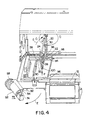
- Figure 4 is an exploded, isometric view illustrating further details of the present construction.
-
- In Figure 1, there is shown an isometric view of an
incubator 10 having incorporated therein, the tilt mechanism of the present invention. Parts of theinfant incubator 10 have been omitted, however, the incubator itself is more specifically shown and described in U.S. Patent 4, 936,824 of Koch et al. - Basically, the
incubator 10 shown in Figure 1 includes abase 12 made of a structural plastics material and which contains the equipment and controls necessary for a functioning incubator. Ahood 14 sits atop thebase 12 ofincubator 10 and is generally comprised of a transparent material so that attending personnel can easily view the infant contained within theincubator 10. As shown in the aforementioned U.S. Patent 4,936,824, thehood 14 also generally includes a front door, hand holes and the like for access to the infant. - Within
incubator 10, there is positioned aninfant bed 16 which is positioned beneath thetransparent hood 14 and rests upon thebase 12. Theinfant bed 16 is used to support the infant and includes a mattress to underlie that infant. As noted, theinfant bed 16 is shown, partially cut-away, in Figure 1 so that the functioning parts of the tilt mechanism can be more readily viewed. - As stated, it is important in the operation of the
incubator 10 that theinfant bed 16 be tiltable to various angles desired by the attending personnel. In certain applications, it is sometimes desirable to raise the level of the head of the infant and at other times the feet of the infant. As described in the present application, however, only one tilt mechanism will be presented, it being obvious that there will normally be a tilt mechanism at both ends of theinfant bed 16, one being the mirror image of the other and therefore the description of but one of the tilt mechanisms is sufficient. - A
recessed area 18 is formed in thebase 12 and as will become apparent, therecessed area 18 receives various of the components of the tilt mechanism so that theinfant bed 16 can be brought to a position level with the upper surface of thebase 12 and the components are contained beneath theinfant bed 16 within therecessed area 18. - A
bed lifter 20 is rotatably affixed to thebase 12 within therecessed area 18 and is rotatable about a pair ofpivot points 22 formed therein. The specific details of thepivot points 22 will be later explained in connection with the details of the assembly and disassembly of the tilt mechanism forincubator 10.Bed lifter 20 has its otherfree end 24 positioned so as to support theinfant bed 16 when it is raised or lowered with respect tobase 12 and can be seen as engaging theinfant bed 16. - Accordingly, as the
bed lifter 20 is rotated about thepivot points 22, thefree end 24 causes theinfant bed 16 to be raised or lowered depending on the direction of the rotation ofbed lifter 20.Bed lifter 20 also includes a pair ofelongated slots 26, (only one of which is shown in Figure 1) the purpose of which will become apparent. - A
bent rod 28 is located beneath theinfant bed 16 and includes anoffset portion 30 that extends upwardly, at times, toward theinfant bed 16. Bentrod 28 is also rotatably mounted to thebase 12 and is rotatable about pivot points 32 (only one of which is shown in Figure 1) that together form an axis of rotation for thebent rod 28. Thebent rod 28 passes through each of theelongated slots 26 ofbed lifter 20 such that thebed lifter 20 is raised or lowered as thebent rod 28 is raised or lowered. - Referring now to Figure 2, in conjunction with Figure 1, there is shown an isometric view, partially broken away, showing further details of the tilt mechanism constructed in accordance with the present invention. In Figure 2, it can be seen that the rotational movement of
bent rod 28 also causes the movement of thebed lifter 20 in the directions of double arrow A. - One end of the
bent rod 28 extends external of theincubator 10 and is coupled to a interface orkey 34. The means of coupling the external end ofbent rod 28 to thekey 34 will be further explained later with reference to the means of disassembling and assembling the tilt mechanism. - Suffice it is to say that the external end of the
bent rod 28 is, during operation, affixed to thekey 34 and rotational motion of thebent rod 28 is transmitted directly to thekey 34 and vice versa. The outer end of thekey 34 is asquare end 36, however any variety of keying arrangement may be used to connect thekey 34 to alever arm 38. A similarshaped hole 40 in thelever arm 38 causes thelever arm 38 andkey 34 to rotate together. - A
link 42 is, in turn, connected to thelever arm 38 at ajunction point 44 that is offset a predetermined distance from the axis of rotation of thebent rod 28, that is, since the center of rotation of thekey 34 is coaxial with the axis of rotation of thebent rod 28, thejunction point 44 is thereby displaced that predetermined distance from the axis of rotation ofkey 34 as well as oflever arm 38. - A
lead screw slide 46 is affixed at ajunction point 48 to the other end of thelink 42.Lead screw slide 46 has internal threads of known pitch and dimensions and slides along a lead screw slide bearing 50 formed within thecover 52. The lead screw slide bearing 50 allows thelead screw slide 46 to move laterally with respect to theincubator 10 but constrains thelead screw slide 46 from rotational movement. Lateral movement oflead screw slide 46 and, of course, link 42 is shown by the double arrow B. - Threadedly engaged to the
lead screw slide 46 is alead screw 54 having, obviously, external threads that are compatible to and threadedly engaged with the internal threads within thelead screw slide 46. Thelead screw 54 is held within a lead screw bearing 56 and is thus allowed to rotate but lateral movement is constrained. Ahand knob 58 of a relatively large size to make gripping by the user convenient, is located at the free end oflead screw 54 and operates to rotatelead screw 54 in the direction of double arrow C. - The
hand knob 58 is preferably made of an elastic material and is pressed on to the end of thelead screw 54 such that when excessive torque is applied to thehand knob 58 by the user, thehand knob 58 rotates relative to thelead screw 54 in the manner of a slip clutch. This clutching action limits the forces on the internal assembly and the potential for damage that could occur due to over-stressing the components is minimized. Thehand knob 58 has arigid ring 59 affixed thereto and which overlaps a smaller diameter concentric ring 61 (shown in Figure 3) on thecover 52 for the purpose of preventing entanglement of tubes or wires which may be used in the operating environment. - Accordingly, the overall operation of the tilt mechanism may now be described. To change the tilt angle of the
infant bed 16, the operator merely grasps and rotates thehand knob 58 in one of the directions of arrow C, thereby also rotatinglead screw 54. Aslead screw 54 is rotated, the threaded engagement with thelead screw slide 46 causes leadscrew slide 46 to move laterally along leadscrew slide bearing 50, thus causinglink 42 to also move laterally along the direction of the double arrow B. That lateral movement oflink 42 thus causes rotation of the key 34 in the direction of double arrow D through the offset distance of thelever arm 38. - Thus, the rotational movement of
hand knob 58 is translated into lateral movement and then again translated into rotational movement of key 34 at a ninety degree axis of rotation with respect to the axis of rotation ofhand knob 58. - Continuing with the operation of the tilt mechanism, therefore, as
key 34 rotates, its connection with thebent rod 28 thereby causes rotation of thebent rod 28 along its axis of rotation. Since thebent rod 28 is fitted within theelongated slots 26 ofbed lifter 20, thebed lifter 20 rotates and thus raises and/or lowers theinfant bed 16 depending, of course, on the direction of rotation of thehand knob 58. - Due to the various mechanisms through which the rotation of
hand knob 58 translates that movement ultimately to theinfant bed 16, and particularly due to the provision oflead screw 54, when the operator stopsrotating hand knob 58, theinfant bed 16 will remain in that selected position. Thus the operator may move theinfant bed 16 to any desired position within ultimate limits, and the bed is infinitely adjustable within those limits and will maintain the position selected without any further locking means. - Thus, the tilt mechanism allows the use of a
large hand knob 58 for convenience the operator for ease in gripping and manipulating thehand knob 58 yet thathand knob 58 is located at the side of theincubator 10 and is therefore in a position that does not interfere with the operation of a front door or impede access to the infant. In addition, the majority of the components are located outside the infant compartment and thus free from contamination. - As a further facet of the present invention, the tilt mechanism is designed so as to be readily disassembled and assembled so that personnel may clean the components.
- Taking, therefore, Figures 3 and 4, there is shown exploded views of the tilt mechanism of the present invention and showing some of the features that allow such disassembly and assembly to be accomplished.
- As shown in Figure 3, the tilt mechanism is basically mounted to the
base 12 ofincubator 10 by means of a mountingbracket 60 which is affixed to the side of theincubator 10 by conventional means, not shown. The mountingbracket 60 interfits with abracket plate 62 by means of ahinge 64. As shown, thehinge 64 comprises acurved tab 66 extending from thebracket plate 62 that partially encircles apin 68 on the mountingbracket 60 such that the two components are hinged together, however, various types of hinge arrangements may be used to create a hinge mechanism between the mountingbracket 60 and thebracket plate 62, it being sufficient that thebracket plate 62 be capable of swinging outwardly from thebase 12 of theincubator 10 as shown by the arrow E of Figure 4. -
Bracket plate 62 is secured to thecover 52 by conventional means such as screws, not shown passing throughholes 70 so that thecover 52 and thebracket plate 62 basically comprise a compacttilt mechanism assembly 72 that swings away from theincubator 10 and which contains those parts of the tilt mechanism commencing with the key 34 through thehand knob 58. - The
tilt mechanism assembly 72 is prevented from swinging outwardly when in operation by means of alatch 74 that is pivotally mounted tobracket plate 62 by apin 76. Thatlatch 74 interacts with thebase 12 ofincubator 10 by means oflatch surface 78 latching underouter wall 80 formed in thebase 12. Theouter wall 80 includes a inner surface which mates with thelatch surface 78 when thelatch 74 is pivoted into its operating position. As can be seen, returning briefly to FIG 1 or 2, when thetilt mechanism assembly 72 is positioned in its operative position, thelatch 74 secures thetilt mechanism assembly 72 to theincubator 10. - The
latch 74 may also have atab 88 for ease of the user in unlatching thelatch 74 for disengagement of thetilt mechanism assembly 72. - Further features allowing the easy removal of the components of the present tilt mechanism include the means of connecting between the
external end 90 of thebent rod 28 which is formed at an angle, generally a 90 degree angle and which is sized so as to fit within agroove 92 formed in the internal face of the key 34. By this means, thebent rod 28 and the key 34 are locked together for rotational movement when thetilt mechanism assembly 72 is in its operative position, yet the two components part readily when thelatch 74 is pivoted upwardly and thetilt mechanism assembly 72 is pivoted outwardly as shown in Figure 4. - In Figure 4, in particular, the details of the
pivot point 22 for thebed lifter 20 is also shown and which also contributes to the disassembly and assembly of the tilt mechanism. Thepivot point 22 is formed in aflange 94 in thebase 12 and features a rectangular entrance opening 96 and acircular opening 98 that receives and retains the generallyrectangular end 100 along the axis of rotation of thebed lifter 20. By this interfitting, thebed lifter 20 may be assembled or disassembled to thebase 12 by being inserted while in a vertical position as shown by arrow F in Figure 4. In the vertical position, the rectangular ends 100 of thebed lifter 20 can be fitted into thecircular opening 98 withinflange 94 since the rectangular ends 100 will fit through therectangular entrance openings 96. - Once the rectangular ends 100 are within the
circular openings 98, however, they are locked within the circular openings as soon as thebed lifter 20 is rotated to a position away from the vertical position. Accordingly, while thebed lifter 20 is freely rotatable with respect to thebase 12, it can only be removed or replaced when it is in the vertical position of Figure 4. - Taking, therefore the disassembly procedures, latch 74 is lifted by the operator which disengages the
tilt mechanism assembly 72 from thebase 12. The operator can then swing thetilt mechanism assembly 72 outwardly as shown by the arrow E of Figure 4. This allows thebent rod 28 to be lifted out of the base 12 which, in turn, allows thebed lifter 20 to be rotated to the vertical position as shown by the arrow G of Figure 4. At this point, thebed lifter 20 and thebent rod 28 may be lifted free of thebase 12 and removed from theincubator 10. Thus, the operator has easy access to all of the parts of the tilt mechanism for cleaning. - The reassembly, of course, is easily accomplished by merely reversing the aforedescribed procedures for disassembly. Thus, the tilt mechanism is easily disassembled for cleaning and is again easily reassembled.
Claims (7)
- A tilt mechanism for adjusting the angular position of an infant bed (16) adapted to underlie an infant contained within an infant incubator (10), comprising:
at least one bent rod (28) contained within the infant incubator (10) and having one free end thereof, the bent rod (28) having an offset portion (30) located beneath the infant bed (16), said offset portion (30) adapted to move said bed (16) upwardly or downwardly as said one free end thereof is rotated about an axis of rotation, characterised in that the tilt mechanism further comprises a lead screw (54) affixed to the exterior of the incubator (10) and being rotatable along a fixed axis of rotation with respect to the incubator (10), linkage means affixed to the incubator (10) and adapted to translate the rotation of said lead screw (54) to cause corresponding rotation of said one free end of said bent rod (28) thereby to raise or lower the infant bed (16) to a desired position. - A tilt mechanism as claimed in Claim 1 wherein said axis of rotation of said bent rod (28) and said lead screw (54) are positioned at an angle of about 90 degrees with respect to each other.
- A tilt mechanism as claimed in Claim 1 or 2 wherein said one free end of said at least one bent rod (28) extends to the exterior of the incubator (10).
- A tilt mechanism as claimed in Claim 3 in which the linkage means comprises a pivot affixed to said external end of said bent rod (28) and having a point (44) offset with respect to the axis of rotation of said rotatable bent rod (28), a linkage (42, 46) having one end thereof affixed to said pivot at said offset point (44) and having the other end threaded, said threaded end (46) being constrained from rotational movement, the lead screw (54) being threadedly engaged to said threaded end (46) of said linkage (44, 46) and being rotatably mounted to the exterior of the incubator (10), said lead screw (54) being rotatable by a user to move said linkage laterally thereby to rotate said at least one bent rod (28) to raise and lower the infant bed (16) to a desired position.
- A tilt mechanism as claimed in any one of claims 1 to 4, in which: at least one bed lifter (20) is positioned beneath the infant bed (16) and rotatably secured to the interior of the incubator (10), said bed lifter (20) being adapted to raise or lower the infant bed (16) as it is rotated by the offset portion (30) of the bent rod (23) engaging and rotating said bed lifter (20) as said at least one bent rod (28) is rotated.
- A tilt mechanism as claimed in Claim 5 wherein said at least one bed lifter (20) includes a plurality of elongated slots (26) and said offset portion (30) of said at least one bent rod (28) extends through said slots (26).
- An incubator containing a tilt mechanism as claimed in any one of claims 1 to 6.
Applications Claiming Priority (2)
| Application Number | Priority Date | Filing Date | Title |
|---|---|---|---|
| US335612 | 1989-04-10 | ||
| US08/335,612 US5531663A (en) | 1994-11-08 | 1994-11-08 | Incubator mattress tilt mechanism |
Publications (2)
| Publication Number | Publication Date |
|---|---|
| EP0711537A1 EP0711537A1 (en) | 1996-05-15 |
| EP0711537B1 true EP0711537B1 (en) | 2001-08-08 |
Family
ID=23312510
Family Applications (1)
| Application Number | Title | Priority Date | Filing Date |
|---|---|---|---|
| EP95307821A Expired - Lifetime EP0711537B1 (en) | 1994-11-08 | 1995-11-02 | Incubator mattress tilt mechanism |
Country Status (4)
| Country | Link |
|---|---|
| US (1) | US5531663A (en) |
| EP (1) | EP0711537B1 (en) |
| JP (1) | JP3718547B2 (en) |
| DE (1) | DE69522076T2 (en) |
Families Citing this family (14)
| Publication number | Priority date | Publication date | Assignee | Title |
|---|---|---|---|---|
| US6071228A (en) * | 1997-09-09 | 2000-06-06 | Hill-Rom, Inc. | Patient-support assembly for thermal support apparatus |
| US6013022A (en) | 1998-06-29 | 2000-01-11 | Jones; Thomas C. | Tilt mechanism for infant care apparatus |
| US6880188B1 (en) | 1999-11-15 | 2005-04-19 | Draeger Medical Infant Care, Inc. | Infant care apparatus with movable infant support |
| WO2001043686A2 (en) | 1999-11-15 | 2001-06-21 | Hill-Rom Services, Inc. | Infant care apparatus with movable infant support |
| US6659935B2 (en) | 2000-09-21 | 2003-12-09 | Hill-Rom Services, Inc. | Lifting apparatus for patient support surface |
| RU2603596C2 (en) | 2011-01-07 | 2016-11-27 | Конинклейке Филипс Электроникс Н.В. | Infant warming assembly with radiant heater and heater surface temperature sensor |
| JP6023088B2 (en) | 2011-02-14 | 2016-11-09 | コーニンクレッカ フィリップス エヌ ヴェKoninklijke Philips N.V. | Bed apparatus having movable heater assembly |
| JP5956243B2 (en) * | 2012-05-09 | 2016-07-27 | アトムメディカル株式会社 | Incubator |
| US9615985B2 (en) | 2012-08-08 | 2017-04-11 | Koninklijke Philips N.V. | Direct drive tilt mechanism for infant-care medical devices |
| JP6261583B2 (en) * | 2012-08-08 | 2018-01-17 | コーニンクレッカ フィリップス エヌ ヴェKoninklijke Philips N.V. | Direct drive tilt mechanism for infant care medical devices |
| CA2894582A1 (en) | 2012-12-11 | 2014-06-19 | Koninklijke Philips N.V. | Method and system for tilting an infant-care medical device |
| US9889055B2 (en) | 2013-03-15 | 2018-02-13 | Segars California Partners, Lp | Infant warming device with rotating patient support power, signal control data and communications |
| LV15786A (en) | 2022-04-26 | 2023-11-20 | Armgate, Sia | Device for adjusting the inclination of the infant bed |
| US20250369562A1 (en) * | 2024-05-31 | 2025-12-04 | Lockheed Martin Corporation | Adjustment assembly for display unit |
Family Cites Families (7)
| Publication number | Priority date | Publication date | Assignee | Title |
|---|---|---|---|---|
| US4734945A (en) * | 1987-05-14 | 1988-04-05 | The Boc Group, Inc. | Tilt mechanism for infant incubator |
| US4936824A (en) | 1987-05-15 | 1990-06-26 | The Boc Group, Inc. | Infant incubator with air curtain |
| US4885918A (en) * | 1988-11-09 | 1989-12-12 | Air-Shields, Inc. | Infant incubator mattress positioning assembly |
| US4934007A (en) * | 1989-07-20 | 1990-06-19 | Metal Craft Manufacturing Ltd. | Deck tilting device |
| US4935974A (en) * | 1989-10-06 | 1990-06-26 | Dick Stebbins | Nursing home bed tilt apparatus |
| JPH0632647B2 (en) * | 1991-10-14 | 1994-05-02 | アトム株式会社 | Bed rest lifting device for incubator |
| GB2272367B (en) * | 1992-11-16 | 1996-01-31 | Hung Yung Feng | A multi-function and automatic sick bed |
-
1994
- 1994-11-08 US US08/335,612 patent/US5531663A/en not_active Expired - Lifetime
-
1995
- 1995-11-02 DE DE69522076T patent/DE69522076T2/en not_active Expired - Fee Related
- 1995-11-02 EP EP95307821A patent/EP0711537B1/en not_active Expired - Lifetime
- 1995-11-08 JP JP28955095A patent/JP3718547B2/en not_active Expired - Fee Related
Also Published As
| Publication number | Publication date |
|---|---|
| EP0711537A1 (en) | 1996-05-15 |
| JP3718547B2 (en) | 2005-11-24 |
| JPH08206161A (en) | 1996-08-13 |
| US5531663A (en) | 1996-07-02 |
| DE69522076D1 (en) | 2001-09-13 |
| DE69522076T2 (en) | 2002-04-25 |
Similar Documents
| Publication | Publication Date | Title |
|---|---|---|
| US5531663A (en) | Incubator mattress tilt mechanism | |
| US6311705B1 (en) | Tilt control device of large-sized parasol | |
| US6003943A (en) | Multi-function control for chair | |
| US6709391B2 (en) | Diagnostic ultrasound system cart with laterally articulating control panel | |
| JP4316966B2 (en) | Surgical console | |
| EP0628290B1 (en) | Stand device of optical instrument for medical use | |
| US7200882B2 (en) | Movable control panel for a patient support | |
| US5754395A (en) | Ergonomic keyboard for a portable computer which is moveable between two positions | |
| JP2002528142A (en) | Hinged panel for warmer | |
| RU2007103536A (en) | ENDOSCOPIC SURGICAL APPARATUS WITH HANDLE WHICH IS ABLE TO HINGE ROTATION OF RELATIVE ROD | |
| US7066505B2 (en) | Combination folding crank handle and lock | |
| JPS63292957A (en) | Tilting mechanism for newborn nursing device | |
| JPS60500428A (en) | Equipment for receiving terminal equipment or similar office equipment | |
| US5694815A (en) | Optical therapeutic and/or diagnostic instrument which can be positioned about at least one spatial axis utilizing a handle assembly | |
| US4805476A (en) | Transmission shift control assembly | |
| JP4093936B2 (en) | Armrest device | |
| JPH0732266Y2 (en) | Manual remote control type door mirror | |
| US11540968B2 (en) | Headrest for surgical chairs | |
| US4113309A (en) | Headrest for dental chair | |
| CN212298460U (en) | Multi-angle turns to screen connecting device and screen strutting arrangement | |
| CN115500881B (en) | Pneumoperitoneum-free supporting device and laparoscopic surgery robot | |
| US20260026653A1 (en) | Multi-step adjustable head tilting mechanism for tilt-head mixer | |
| JP2001299680A (en) | Endoscope operation device | |
| JPH09149877A (en) | Endoscope holding device | |
| JP3650568B2 (en) | Endoscope operation device |
Legal Events
| Date | Code | Title | Description |
|---|---|---|---|
| PUAI | Public reference made under article 153(3) epc to a published international application that has entered the european phase |
Free format text: ORIGINAL CODE: 0009012 |
|
| AK | Designated contracting states |
Kind code of ref document: A1 Designated state(s): DE FR GB |
|
| 17P | Request for examination filed |
Effective date: 19961030 |
|
| RAP1 | Party data changed (applicant data changed or rights of an application transferred) |
Owner name: DATEX-OHMEDA, INC. |
|
| 17Q | First examination report despatched |
Effective date: 19990903 |
|
| GRAG | Despatch of communication of intention to grant |
Free format text: ORIGINAL CODE: EPIDOS AGRA |
|
| GRAG | Despatch of communication of intention to grant |
Free format text: ORIGINAL CODE: EPIDOS AGRA |
|
| GRAH | Despatch of communication of intention to grant a patent |
Free format text: ORIGINAL CODE: EPIDOS IGRA |
|
| GRAH | Despatch of communication of intention to grant a patent |
Free format text: ORIGINAL CODE: EPIDOS IGRA |
|
| GRAA | (expected) grant |
Free format text: ORIGINAL CODE: 0009210 |
|
| AK | Designated contracting states |
Kind code of ref document: B1 Designated state(s): DE FR GB |
|
| RIN1 | Information on inventor provided before grant (corrected) |
Inventor name: SIMENAUER, ROBERT M. Inventor name: KREMENCHUGSKY, VLADIMIR Inventor name: JONES, THOMAS C. Inventor name: HODGE, COLIN G. Inventor name: GLOYD, DAVID A. |
|
| REF | Corresponds to: |
Ref document number: 69522076 Country of ref document: DE Date of ref document: 20010913 |
|
| ET | Fr: translation filed | ||
| REG | Reference to a national code |
Ref country code: GB Ref legal event code: IF02 |
|
| PLBE | No opposition filed within time limit |
Free format text: ORIGINAL CODE: 0009261 |
|
| STAA | Information on the status of an ep patent application or granted ep patent |
Free format text: STATUS: NO OPPOSITION FILED WITHIN TIME LIMIT |
|
| 26N | No opposition filed | ||
| PGFP | Annual fee paid to national office [announced via postgrant information from national office to epo] |
Ref country code: FR Payment date: 20041119 Year of fee payment: 10 |
|
| PGFP | Annual fee paid to national office [announced via postgrant information from national office to epo] |
Ref country code: DE Payment date: 20041230 Year of fee payment: 10 |
|
| PGFP | Annual fee paid to national office [announced via postgrant information from national office to epo] |
Ref country code: GB Payment date: 20051026 Year of fee payment: 11 |
|
| PG25 | Lapsed in a contracting state [announced via postgrant information from national office to epo] |
Ref country code: DE Free format text: LAPSE BECAUSE OF NON-PAYMENT OF DUE FEES Effective date: 20060601 |
|
| PG25 | Lapsed in a contracting state [announced via postgrant information from national office to epo] |
Ref country code: FR Free format text: LAPSE BECAUSE OF NON-PAYMENT OF DUE FEES Effective date: 20060731 |
|
| REG | Reference to a national code |
Ref country code: FR Ref legal event code: ST Effective date: 20060731 |
|
| GBPC | Gb: european patent ceased through non-payment of renewal fee |
Effective date: 20061102 |
|
| PG25 | Lapsed in a contracting state [announced via postgrant information from national office to epo] |
Ref country code: GB Free format text: LAPSE BECAUSE OF NON-PAYMENT OF DUE FEES Effective date: 20061102 |