JP4316966B2 - Surgical console - Google Patents
Surgical console Download PDFInfo
- Publication number
- JP4316966B2 JP4316966B2 JP2003313837A JP2003313837A JP4316966B2 JP 4316966 B2 JP4316966 B2 JP 4316966B2 JP 2003313837 A JP2003313837 A JP 2003313837A JP 2003313837 A JP2003313837 A JP 2003313837A JP 4316966 B2 JP4316966 B2 JP 4316966B2
- Authority
- JP
- Japan
- Prior art keywords
- panel display
- cable
- surgical console
- spindle assembly
- articulation mechanism
- Prior art date
- Legal status (The legal status is an assumption and is not a legal conclusion. Google has not performed a legal analysis and makes no representation as to the accuracy of the status listed.)
- Expired - Lifetime
Links
- 230000020347 spindle assembly Effects 0.000 claims description 18
- 230000008878 coupling Effects 0.000 claims description 5
- 238000010168 coupling process Methods 0.000 claims description 5
- 238000005859 coupling reaction Methods 0.000 claims description 5
- 238000010276 construction Methods 0.000 abstract 1
- 238000001356 surgical procedure Methods 0.000 description 2
- 230000005484 gravity Effects 0.000 description 1
- 238000012986 modification Methods 0.000 description 1
- 230000004048 modification Effects 0.000 description 1
- 230000002093 peripheral effect Effects 0.000 description 1
Images


Classifications
-
- A—HUMAN NECESSITIES
- A61—MEDICAL OR VETERINARY SCIENCE; HYGIENE
- A61B—DIAGNOSIS; SURGERY; IDENTIFICATION
- A61B50/00—Containers, covers, furniture or holders specially adapted for surgical or diagnostic appliances or instruments, e.g. sterile covers
- A61B50/20—Holders specially adapted for surgical or diagnostic appliances or instruments
-
- A—HUMAN NECESSITIES
- A61—MEDICAL OR VETERINARY SCIENCE; HYGIENE
- A61B—DIAGNOSIS; SURGERY; IDENTIFICATION
- A61B50/00—Containers, covers, furniture or holders specially adapted for surgical or diagnostic appliances or instruments, e.g. sterile covers
- A61B50/10—Furniture specially adapted for surgical or diagnostic appliances or instruments
- A61B50/13—Trolleys, e.g. carts
-
- A—HUMAN NECESSITIES
- A61—MEDICAL OR VETERINARY SCIENCE; HYGIENE
- A61B—DIAGNOSIS; SURGERY; IDENTIFICATION
- A61B17/00—Surgical instruments, devices or methods, e.g. tourniquets
- A61B2017/00017—Electrical control of surgical instruments
-
- A—HUMAN NECESSITIES
- A61—MEDICAL OR VETERINARY SCIENCE; HYGIENE
- A61B—DIAGNOSIS; SURGERY; IDENTIFICATION
- A61B17/00—Surgical instruments, devices or methods, e.g. tourniquets
- A61B2017/00017—Electrical control of surgical instruments
- A61B2017/00199—Electrical control of surgical instruments with a console, e.g. a control panel with a display
-
- A—HUMAN NECESSITIES
- A61—MEDICAL OR VETERINARY SCIENCE; HYGIENE
- A61B—DIAGNOSIS; SURGERY; IDENTIFICATION
- A61B50/00—Containers, covers, furniture or holders specially adapted for surgical or diagnostic appliances or instruments, e.g. sterile covers
- A61B50/30—Containers specially adapted for packaging, protecting, dispensing, collecting or disposing of surgical or diagnostic appliances or instruments
- A61B50/33—Trays
-
- A—HUMAN NECESSITIES
- A61—MEDICAL OR VETERINARY SCIENCE; HYGIENE
- A61M—DEVICES FOR INTRODUCING MEDIA INTO, OR ONTO, THE BODY; DEVICES FOR TRANSDUCING BODY MEDIA OR FOR TAKING MEDIA FROM THE BODY; DEVICES FOR PRODUCING OR ENDING SLEEP OR STUPOR
- A61M2209/00—Ancillary equipment
- A61M2209/08—Supports for equipment
- A61M2209/082—Mounting brackets, arm supports for equipment
Abstract
Description
本発明は、概して外科用コンソールの分野、特に、顕微外科用コンソールに使用されるパネルディスプレーに関する。 The present invention relates generally to the field of surgical consoles, and more particularly to panel displays used in microsurgical consoles.
現代の手術、特に、眼科手術の間において、外科医は多様な気体式および電子式顕微外科用ハンドピースを使用する。ハンドピースは、マイクロプロセッサーで動く外科用コンソールであって足踏みスイッチ(footswitch)、赤外線遠隔制御装置およびタッチスクリーンパネルディスプレーのような多様な周辺機器により外科医または助手からの入力を受け取る外科用コンソールにより操作される。タッチスクリーンパネルディスプレーに関しては、好ましくはこれらの機器は調整可能であり、従来技術の外科用コンソールでは旋回動作および傾斜動作の二つの軸線が提供され、本発明以前においては、これらの限定された動作を提供するために、電力供給コードおよび制御信号コードは、独立しているが長さ方向に沿って結合されている2つ以上の部分に分離される必要があった。このような構造は、コンソールの構造に望ましくない複雑さを付加し、パネルディスプレーに望ましくない電気ノイズを付加する。 During modern surgery, particularly ophthalmic surgery, surgeons use a variety of gas and electronic microsurgical handpieces. The handpiece is a microprocessor-operated surgical console operated by a surgical console that receives input from the surgeon or assistant by a variety of peripheral devices such as footswitches, infrared remote controls and touch screen panel displays. Is done. For touch screen panel displays, these instruments are preferably adjustable, and prior art surgical consoles are provided with two axes, pivoting and tilting, prior to the present invention these limited movements. In order to provide the power supply code and the control signal code had to be separated into two or more parts that were independent but coupled along the length. Such a structure adds undesirable complexity to the structure of the console and adds undesirable electrical noise to the panel display.
従って、電気ノイズを低減する、より簡単な構造を備えるパネルディスプレーを有する外科用コンソールの必要性が存続する。 Accordingly, there remains a need for a surgical console having a panel display with a simpler structure that reduces electrical noise.
本発明は、旋回軸線、回転軸線および傾斜軸線を介したパネルディスプレーの関節結合を許可する3軸ジンバル上に取り付けられたパネルディスプレーを有する外科用コンソールを提供することにより、従来技術の外科用コンソールを改良する。関節結合機構は、パネルディスプレーの大きな回転を可能にする単一の連続するケーブルともに、二つの螺旋状のケーブルラップを使用する。連続するケーブルは構造を簡単にし、パネルディスプレーへの電気信号ノイズを最小化する。 The present invention provides a surgical console having a panel display mounted on a three-axis gimbal that allows articulation of the panel display via a pivot axis, a rotation axis and a tilt axis. To improve. The articulation mechanism uses two helical cable wraps along with a single continuous cable that allows large rotation of the panel display. The continuous cable simplifies the structure and minimizes electrical signal noise to the panel display.
よって、本発明の一つの目的は、旋回軸線、回転軸線および傾斜軸線を介したパネルディスプレーの関節結合を許可する3軸ジンバル上に取り付けられるパネルディスプレーを有する外科用コンソールを提供することである。 Accordingly, one object of the present invention is to provide a surgical console having a panel display mounted on a three-axis gimbal that allows articulation of the panel display via a pivot axis, a rotation axis, and a tilt axis.
本発明のもう一つの目的は、パネルディスプレーの大きな回転を可能にする単一の連続するケーブルを使用し二つの螺旋状のケーブルラップを使用する関節結合機構上に取り付けられるパネルディスプレーを有する外科用コンソールを提供することである。 Another object of the present invention is a surgical device having a panel display mounted on an articulating mechanism using a single continuous cable and using two helical cable wraps to allow large rotation of the panel display. Is to provide a console.
本発明の、これらの利点、他の利点、および目的は、以下の詳細な説明および特許請求の範囲から明らかになりうる。 These and other advantages and objects of the invention will be apparent from the following detailed description and claims.
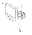
図1に最も良く示されているように、本発明の外科用コンソール10は、概して、関節結合機構16によりコンソール10の本体14に取り付けられたパネルディスプレー12を有する。図2から図7に最も良く示されているように、関節結合機構16は、概して、ベース18と、上側ケーブルラップ21を有する上側スピンドル組立体20と、下側ケーブルラップ22を有する下側スピンドル組立体23と、ケーブル24とを有する。上側スピンドル組立体20は任意の適当なデザインでよいが、概して、(図示されていない)適当なドラッグブレーキ(drag brake)と一緒にシャフト19を有する。ケーブル24は、好ましくは、一つの連続していて長さの途切れないケーブルであり、関節結合機構16を通してディスプレー12をコンソール10へ接続するためのコネクター25を両端に有する。
As best shown in FIG. 1, the
図3および図4に最も良く示されているように、ケーブル24は、上側スピンドル組立体20内の螺旋状の上側ケーブルラップ21の周囲に巻き付き、ベース18内でネジ26および締め具28により所定位置に保持される。上側ケーブルラップ21は、ケーブル24を引っ張ることなく、または損傷することなく、上側スピンドル組立体20上でパネル12が回転することを可能にする。上側スピンドル組立体20は、少なくとも90°にわたり、好ましくは、少なくとも225°にわたりスピンドル19周りにパネルディスプレー12が回転することを可能にする。また、上側スピンドル組立体20はピボットアーム30を有する。図7に最も良く示されているように、垂直な取り付けアーム32は、ピボットアーム30に回転するように取り付けられ、取り付けアーム32にパネルディスプレー12を取り付けることを可能にするための取り付け穴部34を有する。取り付けアーム32はパネルディスプレー12を傾けることを可能とし、このような動きは、ピボットアーム30上で滑動可能に受け入れられるスプリング36により援助される。また、スプリング36は重力相殺機能を有し、パネルディスプレー12の重量がパネルディスプレー12を下方向へ回転することを妨げる。さらに、ピボットアーム30は、(図示されていない)適当なドラッグブレーキを有してもよい。好ましくは、ピボットアーム30および取り付けアーム32は、パネルディスプレー12がベース18に当接して平らに折り畳まれるように前方および後方へ傾けられることが可能なように、十分な範囲の動きを可能とし、好ましくは、少なくとも95°の動きを可能にする。
As best shown in FIGS. 3 and 4, the
図5および図6に最も良く示されているように、下側スピンドル組立体23はスピンドル38と、締め具プレート40と、ネジ42と、下側ケーブルラップ22とを有する。スピンドル38は任意の適当なデザインでよいが、概して、シャフト39と、ハウジング41と、(図示されていない)適当なドラッグブレーキとを有する。ネジ42は締め具プレート40と、下側ケーブルラップ22と、ベース18とを通してスピンドル38内へ受け入れられる。ケーブル24は、ネジ44および締め具46により締め具プレート40へ固定される。スピンドル38および下側ケーブルラップ22は、コンソール10上の下側ベース18の回転(旋回)を可能にするように、好ましくは少なくとも90°にわたり、さらに好ましくは少なくとも180°にわたり回転(旋回)を可能にするように、前述のようにベース18内で動作する。
As best shown in FIGS. 5 and 6, the
使用においては、本発明の組立体16は、パネルディスプレー12の、(上側スピンドル組立体20周りの)回転、(ピボットアーム30周りの)傾斜および(下側スピンドル組立体23周りの)旋回の3つの軸線周りの回転を可能にする。上側ケーブルラップ21および下側ケーブルラップ22は、螺旋形状でケーブル24を渦巻き状に巻き、ケーブル24を引っ張ることなくまたは損傷することなく、上側スピンドル組立体20および下側スピンドル組立体23の回転を可能とする。また、このような構造は、コンソール10とパネルディスプレー12との間の中間の途切れまたは接合部無しに、連続していて途切れないケーブル24の使用を可能にし、よって、構造を簡単にし、且つ、パネルディスプレー12への望ましくない電気ノイズを低減する。
In use, the
この記載は、例証および説明のために与えられるものである。特許請求の範囲に記載の発明の範囲と精神から逸脱しない変更が可能であることは当業者により理解されうる。 This description is given for purposes of illustration and explanation. It can be understood by those skilled in the art that modifications can be made without departing from the scope and spirit of the claimed invention.
10…外科用コンソール
12…パネルディスプレー
16…関節結合機構
10 ...
Claims (6)
a)外装部を有する本体(14)と、
b)関節結合機構(16)により前記本体の前記外装部に取り付けられるパネルディスプレー(12)とを有し、
前記関節結合機構は、少なくとも3つの軸線周りの前記パネルディスプレーの動作を可能にし、
前記関節結合機構は、上側スピンドル組立体(20)および下側スピンドル組立体(23)を有し、前記上側スピンドル組立体は前記関節結合機構(16)に前記パネルディスプレー(12)を取り付け、前記下側スピンドル組立体は前記コンソールの前記本体(14)に前記関節結合機構を取り付け、
前記上側スピンドル組立体(20)は上側ケーブルラップ(21)を有し、前記下側スピンドル組立体(23)は下側ケーブルラップ(22)を有し、前記上側ケーブルラップおよび前記下側ケーブルラップのそれぞれは、前記パネルディスプレー(12)を前記本体(14)へ接続するケーブルを引っ張ることなくまたは損傷することなく、上側スピンドル組立体及び下側スピンドル組立体の回転を可能とする、外科用コンソール。 In the surgical console (10)
a) a body (14) having an exterior part;
b) a panel display (12) attached to the exterior portion of the main body by a joint coupling mechanism (16) ;
The articulation mechanism enables operation of the panel display about at least three axes ;
The joint coupling mechanism includes an upper spindle assembly (20) and a lower spindle assembly (23), and the upper spindle assembly attaches the panel display (12) to the joint coupling mechanism (16). A lower spindle assembly attaches the articulation mechanism to the body (14) of the console;
The upper spindle assembly (20) has an upper cable wrap (21), and the lower spindle assembly (23) has a lower cable wrap (22), the upper cable wrap and the lower cable wrap. Each of which is capable of rotating the upper and lower spindle assemblies without pulling or damaging the cable connecting the panel display (12) to the body (14). .
Applications Claiming Priority (1)
| Application Number | Priority Date | Filing Date | Title |
|---|---|---|---|
| US10/236,601 US7044568B2 (en) | 2002-09-05 | 2002-09-05 | Surgical console |
Publications (3)
| Publication Number | Publication Date |
|---|---|
| JP2004097819A JP2004097819A (en) | 2004-04-02 |
| JP2004097819A5 JP2004097819A5 (en) | 2005-12-22 |
| JP4316966B2 true JP4316966B2 (en) | 2009-08-19 |
Family
ID=31715318
Family Applications (1)
| Application Number | Title | Priority Date | Filing Date |
|---|---|---|---|
| JP2003313837A Expired - Lifetime JP4316966B2 (en) | 2002-09-05 | 2003-09-05 | Surgical console |
Country Status (14)
| Country | Link |
|---|---|
| US (1) | US7044568B2 (en) |
| EP (1) | EP1396235B1 (en) |
| JP (1) | JP4316966B2 (en) |
| CN (1) | CN1298291C (en) |
| AT (1) | ATE285722T1 (en) |
| AU (1) | AU2003231647B2 (en) |
| BR (1) | BR0304123A (en) |
| CA (1) | CA2434349C (en) |
| DE (1) | DE60300250T2 (en) |
| DK (1) | DK1396235T3 (en) |
| ES (1) | ES2233905T3 (en) |
| IL (1) | IL156911A (en) |
| MX (1) | MXPA03006712A (en) |
| ZA (1) | ZA200305417B (en) |
Families Citing this family (36)
| Publication number | Priority date | Publication date | Assignee | Title |
|---|---|---|---|---|
| US20070218751A1 (en) * | 2004-03-11 | 2007-09-20 | Element Labs, Inc. | Mounting system for light tiles attached to tensioned cables |
| US8191909B2 (en) * | 2005-01-10 | 2012-06-05 | Livengood Engineering, Inc. | Modular patient support system |
| WO2006074473A2 (en) * | 2005-01-10 | 2006-07-13 | Livengood Engineering, Inc. | Modular patient support system |
| JP4709590B2 (en) * | 2005-06-28 | 2011-06-22 | 株式会社日立メディコ | Ultrasonic diagnostic equipment |
| US7770860B1 (en) | 2005-11-10 | 2010-08-10 | Modular Services Company | Medical service system on articulating arm with electromagnetic brakes |
| US9545338B2 (en) | 2006-01-20 | 2017-01-17 | Lensar, Llc. | System and method for improving the accommodative amplitude and increasing the refractive power of the human lens with a laser |
| US9889043B2 (en) | 2006-01-20 | 2018-02-13 | Lensar, Inc. | System and apparatus for delivering a laser beam to the lens of an eye |
| US10842675B2 (en) | 2006-01-20 | 2020-11-24 | Lensar, Inc. | System and method for treating the structure of the human lens with a laser |
| AU2007265334B2 (en) * | 2006-06-28 | 2011-04-07 | Alcon Inc. | Control display positioning system |
| US8262553B2 (en) * | 2006-09-18 | 2012-09-11 | Novartis Ag | Ophthalmic surgical console system |
| TWI326437B (en) * | 2006-12-29 | 2010-06-21 | Chimei Innolux Corp | Display device |
| US8500723B2 (en) | 2008-07-25 | 2013-08-06 | Lensar, Inc. | Liquid filled index matching device for ophthalmic laser procedures |
| US8480659B2 (en) | 2008-07-25 | 2013-07-09 | Lensar, Inc. | Method and system for removal and replacement of lens material from the lens of an eye |
| US20100060121A1 (en) * | 2008-09-10 | 2010-03-11 | Dental Equipment, Llc Dba Pelton & Crane | Modular storage unit for a cabinet |
| US8070120B2 (en) * | 2008-11-19 | 2011-12-06 | Hoffman Enclosures, Inc. | Vertical motion pendant arm |
| EP2456385B1 (en) | 2009-07-24 | 2015-07-22 | Lensar, Inc. | System for performing ladar assisted procedures on the lens of an eye |
| US8617146B2 (en) | 2009-07-24 | 2013-12-31 | Lensar, Inc. | Laser system and method for correction of induced astigmatism |
| US8382745B2 (en) | 2009-07-24 | 2013-02-26 | Lensar, Inc. | Laser system and method for astigmatic corrections in association with cataract treatment |
| EP2456384B1 (en) | 2009-07-24 | 2023-09-20 | LENSAR, Inc. | System for providing laser shot patterns to the lens of an eye |
| US8758332B2 (en) | 2009-07-24 | 2014-06-24 | Lensar, Inc. | Laser system and method for performing and sealing corneal incisions in the eye |
| US8658948B2 (en) * | 2009-12-17 | 2014-02-25 | Alcon Research, Ltd. | Docking station with temperature control and electronic identification system |
| WO2011094678A1 (en) | 2010-02-01 | 2011-08-04 | Lensar, Inc. | Purkinjie image-based alignment of suction ring in ophthalmic applications |
| CN106974614B (en) | 2010-10-15 | 2019-04-26 | 雷萨公司 | The system and method for the scan control illumination of the structure of inside of eye |
| USD694890S1 (en) * | 2010-10-15 | 2013-12-03 | Lensar, Inc. | Laser system for treatment of the eye |
| USD695408S1 (en) * | 2010-10-15 | 2013-12-10 | Lensar, Inc. | Laser system for treatment of the eye |
| US10463541B2 (en) | 2011-03-25 | 2019-11-05 | Lensar, Inc. | System and method for correcting astigmatism using multiple paired arcuate laser generated corneal incisions |
| US8988483B2 (en) * | 2011-06-06 | 2015-03-24 | Ted Schwartz | Mobile conferencing system |
| DE102012105912A1 (en) * | 2012-07-03 | 2014-01-09 | B. Braun Avitum Ag | Holding device and medical device for extracorporeal blood treatment with holding device |
| USD714453S1 (en) | 2012-08-30 | 2014-09-30 | Guided Therapeutics, Inc. | Hand held unit for diagnostics or measurement |
| PL402394A1 (en) * | 2013-01-08 | 2014-07-21 | Kriosystem Spółka Z Ograniczoną Odpowiedzialnością | Cryotherapy device with the control panel |
| USD787073S1 (en) | 2015-03-12 | 2017-05-16 | Lgms, Llc | Patient support cart with mounting plate |
| USD783389S1 (en) | 2015-03-12 | 2017-04-11 | Lgms, Llc | Mounting plate for a patient support cart |
| WO2017062921A1 (en) | 2015-10-07 | 2017-04-13 | MAQUET CARDIOPULMONARY GmbH | Medical device |
| US10364033B2 (en) * | 2017-12-21 | 2019-07-30 | Adient Aerospace Llc | Table apparatus |
| US11793959B2 (en) | 2018-03-16 | 2023-10-24 | Drägerwerk AG & Co. KGaA | Ventilator with adjustable user interface |
| CN113163140B (en) * | 2020-01-22 | 2023-05-09 | 海信视像科技股份有限公司 | Display device |
Family Cites Families (22)
| Publication number | Priority date | Publication date | Assignee | Title |
|---|---|---|---|---|
| US4437677A (en) * | 1982-02-09 | 1984-03-20 | Haig Ksayian | Hand and/or foot propelled vehicle |
| US4625731A (en) | 1984-10-10 | 1986-12-02 | Picker International, Inc. | Ultrasonic image display mounting |
| US5157603A (en) | 1986-11-06 | 1992-10-20 | Storz Instrument Company | Control system for ophthalmic surgical instruments |
| US5028746A (en) * | 1989-08-31 | 1991-07-02 | Rosemount Inc. | Cable protector for wound cable |
| US5627584A (en) | 1991-01-17 | 1997-05-06 | Olympus Optical Co., Ltd. | Endoscope system with centralized control of associated peripheral equipment |
| US5179447A (en) * | 1991-04-16 | 1993-01-12 | Hughes-Avicom International, Inc. | Personal video player and monitor assembly for airline passenger seat console |
| US5177616A (en) * | 1991-12-02 | 1993-01-05 | Matsushita Avionics Systems | Stowable video display assembly |
| US5667179A (en) * | 1994-09-30 | 1997-09-16 | Rosen; John B. | Ratcheting articulable monitor support and presentation device |
| ES2215229T3 (en) * | 1996-05-30 | 2004-10-01 | Technolas Gmbh Ophthalmologische Systeme | LASER SYSTEM EXCIMERO FOR EYE SURGERY. |
| US6022088A (en) | 1996-08-29 | 2000-02-08 | Bausch & Lomb Surgical, Inc. | Ophthalmic microsurgical system |
| US5924988A (en) * | 1997-04-11 | 1999-07-20 | Acuson Corporation | Ultrasound system display device |
| US6007036A (en) * | 1997-09-23 | 1999-12-28 | Rosen Products Llc | Stowable support apparatus |
| US5996954A (en) * | 1997-10-14 | 1999-12-07 | Rosen Products Llc | Stowable support apparatus |
| US6102476A (en) * | 1998-03-11 | 2000-08-15 | May; Gordon G. | Computer furniture with integrated computer |
| US6024427A (en) * | 1998-04-21 | 2000-02-15 | Kimball International, Inc. | Mobile office furniture pedestal unit with handle and auxiliary worksurface and storage |
| US6220658B1 (en) * | 1998-10-16 | 2001-04-24 | Johnson Controls Technology Company | Retractable tray table |
| US6145926A (en) * | 1998-11-17 | 2000-11-14 | Lin; Kuan Jen | Computer chair device |
| US6447451B1 (en) * | 1999-05-04 | 2002-09-10 | Sonosite, Inc. | Mobile ultrasound diagnostic instrument and docking stand |
| US6510049B2 (en) * | 2000-01-06 | 2003-01-21 | Rosen Products Llc | Adjustable display monitor unit |
| CA2334143A1 (en) * | 2001-02-05 | 2002-08-05 | Inscape Corporation | Multi-positional mouse pad |
| TW495130U (en) * | 2001-02-09 | 2002-07-11 | Acer Inc | Flat display device and the rotatory structure thereof |
| US6614969B2 (en) * | 2001-07-26 | 2003-09-02 | The Ludlow Company, Lp | High speed electronic remote medical imaging system and method |
-
2002
- 2002-09-05 US US10/236,601 patent/US7044568B2/en not_active Expired - Lifetime
-
2003
- 2003-07-04 CA CA002434349A patent/CA2434349C/en not_active Expired - Lifetime
- 2003-07-11 DK DK03077206T patent/DK1396235T3/en active
- 2003-07-11 AT AT03077206T patent/ATE285722T1/en active
- 2003-07-11 DE DE60300250T patent/DE60300250T2/en not_active Expired - Lifetime
- 2003-07-11 ES ES03077206T patent/ES2233905T3/en not_active Expired - Lifetime
- 2003-07-11 EP EP03077206A patent/EP1396235B1/en not_active Expired - Lifetime
- 2003-07-14 IL IL156911A patent/IL156911A/en active IP Right Grant
- 2003-07-14 ZA ZA200305417A patent/ZA200305417B/en unknown
- 2003-07-28 MX MXPA03006712A patent/MXPA03006712A/en active IP Right Grant
- 2003-08-06 AU AU2003231647A patent/AU2003231647B2/en not_active Expired
- 2003-08-13 CN CNB031278736A patent/CN1298291C/en not_active Expired - Lifetime
- 2003-09-01 BR BR0304123-9A patent/BR0304123A/en not_active Application Discontinuation
- 2003-09-05 JP JP2003313837A patent/JP4316966B2/en not_active Expired - Lifetime
Also Published As
| Publication number | Publication date |
|---|---|
| CN1298291C (en) | 2007-02-07 |
| EP1396235A1 (en) | 2004-03-10 |
| ZA200305417B (en) | 2004-05-20 |
| CA2434349C (en) | 2009-06-02 |
| EP1396235B1 (en) | 2004-12-29 |
| AU2003231647B2 (en) | 2008-01-24 |
| US7044568B2 (en) | 2006-05-16 |
| BR0304123A (en) | 2004-06-08 |
| DK1396235T3 (en) | 2005-04-25 |
| AU2003231647A1 (en) | 2004-03-25 |
| MXPA03006712A (en) | 2004-03-10 |
| ATE285722T1 (en) | 2005-01-15 |
| DE60300250T2 (en) | 2005-12-22 |
| IL156911A (en) | 2008-08-07 |
| JP2004097819A (en) | 2004-04-02 |
| ES2233905T3 (en) | 2005-06-16 |
| DE60300250D1 (en) | 2005-02-03 |
| US20040046487A1 (en) | 2004-03-11 |
| IL156911A0 (en) | 2004-02-08 |
| CA2434349A1 (en) | 2004-03-05 |
| CN1483385A (en) | 2004-03-24 |
Similar Documents
| Publication | Publication Date | Title |
|---|---|---|
| JP4316966B2 (en) | Surgical console | |
| US6695774B2 (en) | Apparatus and method for controlling endoscopic instruments | |
| JP4222706B2 (en) | Medical instrument holding device | |
| JP5265818B2 (en) | Medical holding device | |
| JP2008155031A (en) | Camera holder device, and its method | |
| KR100936928B1 (en) | Surgical robot | |
| AU6486094A (en) | Endoscopic surgical instrument with pivotable and rotatable staple cartridge | |
| US10639066B2 (en) | System for controlling displacement of an intervention device | |
| JP5663155B2 (en) | Endoscope device | |
| JP4469439B2 (en) | Medical manipulator | |
| JP3670325B2 (en) | Medical device holding device | |
| US20230080541A1 (en) | Surgical instrument holding device and surgical assistance device | |
| JP2002103255A (en) | Support device of manipulator | |
| JP4422262B2 (en) | Endoscopic surgery system | |
| JP2005007189A (en) | Surgical instrument holding device | |
| JP2001120492A (en) | Endoscope system device | |
| JP2001145639A (en) | Manipulator controller | |
| CN113951948B (en) | Surgical instrument control unit | |
| JPH09149877A (en) | Endoscope holding device | |
| JP2002191545A (en) | Medical operation tool holding device | |
| JP2003245286A (en) | Endoscope operating system | |
| CN116175526A (en) | 6-degree-of-freedom medical miniature mechanical arm |
Legal Events
| Date | Code | Title | Description |
|---|---|---|---|
| A521 | Request for written amendment filed |
Free format text: JAPANESE INTERMEDIATE CODE: A523 Effective date: 20051102 |
|
| A621 | Written request for application examination |
Free format text: JAPANESE INTERMEDIATE CODE: A621 Effective date: 20051102 |
|
| A131 | Notification of reasons for refusal |
Free format text: JAPANESE INTERMEDIATE CODE: A131 Effective date: 20081209 |
|
| A521 | Request for written amendment filed |
Free format text: JAPANESE INTERMEDIATE CODE: A523 Effective date: 20090306 |
|
| TRDD | Decision of grant or rejection written | ||
| A01 | Written decision to grant a patent or to grant a registration (utility model) |
Free format text: JAPANESE INTERMEDIATE CODE: A01 Effective date: 20090421 |
|
| A01 | Written decision to grant a patent or to grant a registration (utility model) |
Free format text: JAPANESE INTERMEDIATE CODE: A01 |
|
| A61 | First payment of annual fees (during grant procedure) |
Free format text: JAPANESE INTERMEDIATE CODE: A61 Effective date: 20090521 |
|
| R150 | Certificate of patent or registration of utility model |
Ref document number: 4316966 Country of ref document: JP Free format text: JAPANESE INTERMEDIATE CODE: R150 Free format text: JAPANESE INTERMEDIATE CODE: R150 |
|
| FPAY | Renewal fee payment (event date is renewal date of database) |
Free format text: PAYMENT UNTIL: 20120529 Year of fee payment: 3 |
|
| FPAY | Renewal fee payment (event date is renewal date of database) |
Free format text: PAYMENT UNTIL: 20130529 Year of fee payment: 4 |
|
| R250 | Receipt of annual fees |
Free format text: JAPANESE INTERMEDIATE CODE: R250 |
|
| FPAY | Renewal fee payment (event date is renewal date of database) |
Free format text: PAYMENT UNTIL: 20130529 Year of fee payment: 4 |
|
| R250 | Receipt of annual fees |
Free format text: JAPANESE INTERMEDIATE CODE: R250 |
|
| R250 | Receipt of annual fees |
Free format text: JAPANESE INTERMEDIATE CODE: R250 |
|
| R250 | Receipt of annual fees |
Free format text: JAPANESE INTERMEDIATE CODE: R250 |
|
| R250 | Receipt of annual fees |
Free format text: JAPANESE INTERMEDIATE CODE: R250 |
|
| R250 | Receipt of annual fees |
Free format text: JAPANESE INTERMEDIATE CODE: R250 |
|
| R250 | Receipt of annual fees |
Free format text: JAPANESE INTERMEDIATE CODE: R250 |
|
| R250 | Receipt of annual fees |
Free format text: JAPANESE INTERMEDIATE CODE: R250 |
|
| S111 | Request for change of ownership or part of ownership |
Free format text: JAPANESE INTERMEDIATE CODE: R313111 Free format text: JAPANESE INTERMEDIATE CODE: R313113 |
|
| S531 | Written request for registration of change of domicile |
Free format text: JAPANESE INTERMEDIATE CODE: R313531 |
|
| S111 | Request for change of ownership or part of ownership |
Free format text: JAPANESE INTERMEDIATE CODE: R313111 Free format text: JAPANESE INTERMEDIATE CODE: R313113 |
|
| S531 | Written request for registration of change of domicile |
Free format text: JAPANESE INTERMEDIATE CODE: R313531 |
|
| R350 | Written notification of registration of transfer |
Free format text: JAPANESE INTERMEDIATE CODE: R350 |
|
| R250 | Receipt of annual fees |
Free format text: JAPANESE INTERMEDIATE CODE: R250 |
|
| R250 | Receipt of annual fees |
Free format text: JAPANESE INTERMEDIATE CODE: R250 |
|
| R250 | Receipt of annual fees |
Free format text: JAPANESE INTERMEDIATE CODE: R250 |
|
| R250 | Receipt of annual fees |
Free format text: JAPANESE INTERMEDIATE CODE: R250 |
|
| EXPY | Cancellation because of completion of term |