EP0710854A2 - X-ray scintillating plate utilizing angled fiber optic rods - Google Patents
X-ray scintillating plate utilizing angled fiber optic rods Download PDFInfo
- Publication number
- EP0710854A2 EP0710854A2 EP95116449A EP95116449A EP0710854A2 EP 0710854 A2 EP0710854 A2 EP 0710854A2 EP 95116449 A EP95116449 A EP 95116449A EP 95116449 A EP95116449 A EP 95116449A EP 0710854 A2 EP0710854 A2 EP 0710854A2
- Authority
- EP
- European Patent Office
- Prior art keywords
- ray
- fiber optic
- ray image
- rods
- image
- Prior art date
- Legal status (The legal status is an assumption and is not a legal conclusion. Google has not performed a legal analysis and makes no representation as to the accuracy of the status listed.)
- Withdrawn
Links
Images

Classifications
-
- G—PHYSICS
- G01—MEASURING; TESTING
- G01T—MEASUREMENT OF NUCLEAR OR X-RADIATION
- G01T1/00—Measuring X-radiation, gamma radiation, corpuscular radiation, or cosmic radiation
- G01T1/16—Measuring radiation intensity
- G01T1/20—Measuring radiation intensity with scintillation detectors
- G01T1/201—Measuring radiation intensity with scintillation detectors using scintillating fibres
-
- G—PHYSICS
- G01—MEASURING; TESTING
- G01T—MEASUREMENT OF NUCLEAR OR X-RADIATION
- G01T1/00—Measuring X-radiation, gamma radiation, corpuscular radiation, or cosmic radiation
- G01T1/16—Measuring radiation intensity
- G01T1/20—Measuring radiation intensity with scintillation detectors
- G01T1/2018—Scintillation-photodiode combinations
- G01T1/20183—Arrangements for preventing or correcting crosstalk, e.g. optical or electrical arrangements for correcting crosstalk
-
- G—PHYSICS
- G01—MEASURING; TESTING
- G01T—MEASUREMENT OF NUCLEAR OR X-RADIATION
- G01T1/00—Measuring X-radiation, gamma radiation, corpuscular radiation, or cosmic radiation
- G01T1/16—Measuring radiation intensity
- G01T1/20—Measuring radiation intensity with scintillation detectors
- G01T1/2018—Scintillation-photodiode combinations
- G01T1/20185—Coupling means between the photodiode and the scintillator, e.g. optical couplings using adhesives with wavelength-shifting fibres
-
- G—PHYSICS
- G01—MEASURING; TESTING
- G01T—MEASUREMENT OF NUCLEAR OR X-RADIATION
- G01T1/00—Measuring X-radiation, gamma radiation, corpuscular radiation, or cosmic radiation
- G01T1/16—Measuring radiation intensity
- G01T1/20—Measuring radiation intensity with scintillation detectors
- G01T1/2018—Scintillation-photodiode combinations
- G01T1/20187—Position of the scintillator with respect to the photodiode, e.g. photodiode surrounding the crystal, the crystal surrounding the photodiode, shape or size of the scintillator
Definitions
- This invention relates in general to x-ray imaging systems and relates more particularly to direct digital x-ray imaging system including a fiber optic scintillating plate in which aliasing and x-ray transmission problems are minimized.
- Screen film x-ray diagnostic imaging is an effective tool for detection and diagnosis of a number of diseases, such as cancer, as well as for assessment of injuries. It is widely believed that improved performance with respect to both image quality and radiation dose could be obtained if x-ray image data were acquired directly in digital form. Such a technology would in turn require fewer moving parts (prone to wear and tear), a smaller package, and less image acquisition and processing time.
- One of the approaches in direct digital x-ray imaging involves the utilization of a scintillating screen that is then imaged by a CCD (charge coupled device) through a lens or a fiber optic light guide.
- CCD charge coupled device
- Some of the requirements for such a screen are high x-ray absorption, high x-ray energy to light photon conversion efficiency, high resolution, large dynamic range.
- Such screens should also be free of spatial artifacts and easily manufacturable.
- Fiber optic scintillating plates seem to have the advantage of having much higher resolution (5 to 15 1p/mm). These fiber optic scintillating plates are made of monolithic bundles of round or hexagonally shaped glass or plastic rods.
- the rods are oriented at a normal angle with respect to an x-ray image plane. (See Fig. 1, rods 10 are normal to the X-Y plane and parallel to the Z axis.)
- the rods are doped with some type of rare earth element, such as terbium, to emit visible light when exposed to x-rays.
- Each rod has its own cladding which is essential in minimizing cross-talk between fibers.
- the fill-factor in these plates can approach 85% with the remaining 15% attributed to the cladding and light absorbing material used in between the rods. Therefor the produced visible light as a result of x-ray absorption within each fiber core will be channeled and directed toward the imaging sensor, such as a CCD. To capture more of this light, one side of the plate is usually coated with a reflective material, such as aluminum.
- Such a scintillating fiber optic plate may also be used in conjunction with other type of sensors such as thin-film transistor (TFT) array or tiled CCD arrays whereby the scintillator may be in direct contact with the array.
- TFT thin-film transistor
- MTF modulation transfer function
- the fiber optic scintillating plates can produce images with very high resolution due to the discrete and channelized nature of the emission of light within the core of each fiber.
- the MTF of a system is defined as the Fourier transform of the system point-spread function (PSF). This means that, in theory, it is possible to measure the MTF by generating the Fourier transform of the image of a point source.
- PSF point-spread function
- the mathematical assumption that is implicit here is that the system is both linear and shift-invariant, i.e., that the location of this point source on the image plan can be chosen arbitrarily. This assumption is invalid in an imaging system in which the image plane is composed of well defined discrete image sensors.
- One way to overcome this problem is to blur the image at the detector level so that the boundaries of the pixels are not as well defined and then to edge enhance the acquired image using image processing techniques. This is often done in CCD based systems.
- U.S. Patent 4,910,405 issued March 20, 1990, inventors Suzuki et al. discloses an x-ray image sensor including a fiber optic face plate, a phosphor screen formed on the x-ray incidence side of the face plate and an image sensing device connected to the other side of the face plate.
- a core material of the face plate is a radiation shielding glass which prevents x-ray damage of the solid-state image sensing device.
- the face plate can be inclined from the normal axis to the screen.
- a fiber optic scintillating plate which is angled to the normal axis of an x-ray image.
- U.S. Patent 4,247,165, issued January 27, 1981, inventor Versluis; U.S. Patent 4,586,781, issued May 6, 1986, inventor Gunther et al.; and U.S. patent 4,914,349, issued April 3, 1990, inventors Matsui et al. disclose fiber optic plates having fibers which are inclined at an angle to an optical plane.
- the fiber optic plates disclosed in these patents purport to solve various optical transmission problems, but are not directed to such problems as prevention of x-ray transmission to an image sensing device.
- a fiber optic scintillating plate which has fibers which are tilted with respect to the x-ray image plane.
- aliasing is eliminated because x-ray photons are absorbed by the angled scintillating cores at various depths, so that they could easily cross the fiber cladding and be absorbed in the neighboring scintillating fiber core.
- the image plane will no longer be composed of well defined discrete pixels and some blurring is introduced that may be later reduced by edge enhancement image processing.
- the transmission of x-rays to the light image detector through the fiber cladding is eliminated since there will be no direct path for x-ray photons through the cladding.
- Fig. 1 is a diagrammatic view of a known fiber optic array.
- Fig. 2 is a diagrammatic view of an x-ray imaging system incorporating an embodiment of the present invention.
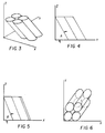
- Figs. 3-6 are diagrammatic views of an embodiment of the present invention.
- an x-ray imaging system incorporating an embodiment of the present invention.
- an x-ray source 12 emits x-rays which are passed through object 14 (such as a body part).
- An x-ray image of the object is projected on to a first face 15 of fiber optic scintillating plate 16 which converts the x-ray image into a corresponding light image which is emitted from second face 17 of plate 16.
- the light image is converted to an x-ray image signal by detector 18 (such as a CCD sensor, a TFT array) after transmission by optical assembly 20 (such as a light guide or lens assembly).
- the x-ray image signal is digitized and processed by image processing circuit 22 for image characteristics, such as tone scale, edge enhancement, segmentation.
- Fiber optic scintillating plate 16 is made of monolithic bundles of round or hexagonally shaped glass or plastic rods 10.
- the rods 10 have first ends 19 coextensive with plate face 15 and second ends 21 coextensive with plate face 17.
- the rods have a core which is doped with some type of material (e.g., a rare earth element such as terbium) which emits visible light when exposed to x-rays.
- a rare earth element such as terbium
- Each rod is clad to minimize cross-talk between rods. The visible light produced in each rod as a result of x-ray absorption is channeled and directed toward the detector 18.
- the rods 10 are tilted with respect to the image plane (Fig. 3).
- the first angle A may be on the Y-Z plane (Fig. 4) and the second angle B could be on the X-Z plane (Fig. 5), or with respect to the row, column, or any direct axis of the formation of fibers.
- Rods 10 are angled so that no x-ray photon will have a direct path through a single fiber core or cladding (Fig. 6).
- the optimum angles A and B will depend on the pixel pitch, pixel spacing, the thickness of the plate 16, and the x-ray absorption of the material used in construction of the plate 16. These angles could have a range of 1 to 89 degrees and are optimized for best performance of the plate 16.
- a fiber optic scintillating plate with normal angle rods may be used and the whole plate may be tilted to obtain the same effective angles and purpose.
- the x-ray to light conversion does not necessarily have to happen within the fiber optic plate and this conversion may be done beforehand by placing a common scintillating plate on the surface of the fiber optic plate.
- Such a scintillating plate may be used in various medical x-ray imaging modalities (Fig. 2).
- the resulting visible image can then be imaged by a CCD via a lens or fiber optic guide or alternatively it can be imaged directly by some other light detector such as a large area CCD or a two dimensional array of photo diodes and thin-film transistors.
- a fiber optic scintillating plate eliminates aliasing and x-ray penetration.
- the aliasing will be eliminated since the x-ray photons are absorbed at various depths, they could easily cross the cladding and be absorbed at the neighboring fiber core. In this manner, the image plane will no longer be composed of well-defined discrete pixels and some blurring is introduced that may be later reduced by edge enhancement algorithms.
- the transmission of x-rays to the detector through the cladding is eliminated since there will be no direct path for those photons through the cladding.
Abstract
Description
- This invention relates in general to x-ray imaging systems and relates more particularly to direct digital x-ray imaging system including a fiber optic scintillating plate in which aliasing and x-ray transmission problems are minimized.
- Screen film x-ray diagnostic imaging is an effective tool for detection and diagnosis of a number of diseases, such as cancer, as well as for assessment of injuries. It is widely believed that improved performance with respect to both image quality and radiation dose could be obtained if x-ray image data were acquired directly in digital form. Such a technology would in turn require fewer moving parts (prone to wear and tear), a smaller package, and less image acquisition and processing time.
- One of the approaches in direct digital x-ray imaging involves the utilization of a scintillating screen that is then imaged by a CCD (charge coupled device) through a lens or a fiber optic light guide. Some of the requirements for such a screen are high x-ray absorption, high x-ray energy to light photon conversion efficiency, high resolution, large dynamic range. Such screens should also be free of spatial artifacts and easily manufacturable.
- Fiber optic scintillating plates seem to have the advantage of having much higher resolution (5 to 15 1p/mm). These fiber optic scintillating plates are made of monolithic bundles of round or hexagonally shaped glass or plastic rods. The rods are oriented at a normal angle with respect to an x-ray image plane. (See Fig. 1,
rods 10 are normal to the X-Y plane and parallel to the Z axis.) The rods are doped with some type of rare earth element, such as terbium, to emit visible light when exposed to x-rays. Each rod has its own cladding which is essential in minimizing cross-talk between fibers. The fill-factor in these plates can approach 85% with the remaining 15% attributed to the cladding and light absorbing material used in between the rods. Therefor the produced visible light as a result of x-ray absorption within each fiber core will be channeled and directed toward the imaging sensor, such as a CCD. To capture more of this light, one side of the plate is usually coated with a reflective material, such as aluminum. - Such a scintillating fiber optic plate may also be used in conjunction with other type of sensors such as thin-film transistor (TFT) array or tiled CCD arrays whereby the scintillator may be in direct contact with the array.
- Two problems of such a fiber optic scintillating plate are MTF (modulation transfer function) problems and x-ray transmission through the cladding.
- The fiber optic scintillating plates can produce images with very high resolution due to the discrete and channelized nature of the emission of light within the core of each fiber. The MTF of a system is defined as the Fourier transform of the system point-spread function (PSF). This means that, in theory, it is possible to measure the MTF by generating the Fourier transform of the image of a point source. The mathematical assumption that is implicit here is that the system is both linear and shift-invariant, i.e., that the location of this point source on the image plan can be chosen arbitrarily. This assumption is invalid in an imaging system in which the image plane is composed of well defined discrete image sensors.
- The practical implications of such a problem may cause aliasing in the acquired image at various spatial frequencies. This effect may be most evident when imaging an object with spatial frequencies at exact multiples of the pixel pitch.
- One way to overcome this problem is to blur the image at the detector level so that the boundaries of the pixels are not as well defined and then to edge enhance the acquired image using image processing techniques. This is often done in CCD based systems.
- Although the absorption of x-rays of the core in the scintillating fiber optic plates is close to 100%, this is not the case for the cladding. Any x-ray photons transmitted through the cladding and striking the detector may cause image blurring and at the same time reduce the lifetime of the detector significantly. This is significant in CCDs when a single x-ray photon may generate so many electrons as to saturate the well and causes unacceptable image blurring.
- U.S. Patent 4,910,405, issued March 20, 1990, inventors Suzuki et al., discloses an x-ray image sensor including a fiber optic face plate, a phosphor screen formed on the x-ray incidence side of the face plate and an image sensing device connected to the other side of the face plate. A core material of the face plate is a radiation shielding glass which prevents x-ray damage of the solid-state image sensing device. The face plate can be inclined from the normal axis to the screen. There is no disclosure in this patent of a fiber optic scintillating plate which is angled to the normal axis of an x-ray image.
- U.S. Patent 4,247,165, issued January 27, 1981, inventor Versluis; U.S. Patent 4,586,781, issued May 6, 1986, inventor Gunther et al.; and U.S. patent 4,914,349, issued April 3, 1990, inventors Matsui et al. disclose fiber optic plates having fibers which are inclined at an angle to an optical plane. The fiber optic plates disclosed in these patents purport to solve various optical transmission problems, but are not directed to such problems as prevention of x-ray transmission to an image sensing device.
- According to the present invention, there is provided a solution to the problems of the prior art relating to fiber optic scintillating plates. According to a feature of the present invention, a fiber optic scintillating plate is provided which has fibers which are tilted with respect to the x-ray image plane. Thus, aliasing is eliminated because x-ray photons are absorbed by the angled scintillating cores at various depths, so that they could easily cross the fiber cladding and be absorbed in the neighboring scintillating fiber core. In this manner, the image plane will no longer be composed of well defined discrete pixels and some blurring is introduced that may be later reduced by edge enhancement image processing. Moreover, the transmission of x-rays to the light image detector through the fiber cladding is eliminated since there will be no direct path for x-ray photons through the cladding.
- Fig. 1 is a diagrammatic view of a known fiber optic array.
- Fig. 2 is a diagrammatic view of an x-ray imaging system incorporating an embodiment of the present invention.
- Figs. 3-6 are diagrammatic views of an embodiment of the present invention.
- Referring now to Fig. 2, there is shown an x-ray imaging system incorporating an embodiment of the present invention. As shown, an x-ray source 12 emits x-rays which are passed through object 14 (such as a body part). An x-ray image of the object is projected on to a
first face 15 of fiberoptic scintillating plate 16 which converts the x-ray image into a corresponding light image which is emitted fromsecond face 17 ofplate 16. The light image is converted to an x-ray image signal by detector 18 (such as a CCD sensor, a TFT array) after transmission by optical assembly 20 (such as a light guide or lens assembly). - The x-ray image signal is digitized and processed by
image processing circuit 22 for image characteristics, such as tone scale, edge enhancement, segmentation. - Fiber
optic scintillating plate 16 is made of monolithic bundles of round or hexagonally shaped glass orplastic rods 10. Therods 10 havefirst ends 19 coextensive withplate face 15 andsecond ends 21 coextensive withplate face 17. The rods have a core which is doped with some type of material (e.g., a rare earth element such as terbium) which emits visible light when exposed to x-rays. Each rod is clad to minimize cross-talk between rods. The visible light produced in each rod as a result of x-ray absorption is channeled and directed toward thedetector 18. - According to the present invention, the
rods 10 are tilted with respect to the image plane (Fig. 3). The first angle A, may be on the Y-Z plane (Fig. 4) and the second angle B could be on the X-Z plane (Fig. 5), or with respect to the row, column, or any direct axis of the formation of fibers.Rods 10 are angled so that no x-ray photon will have a direct path through a single fiber core or cladding (Fig. 6). The optimum angles A and B will depend on the pixel pitch, pixel spacing, the thickness of theplate 16, and the x-ray absorption of the material used in construction of theplate 16. These angles could have a range of 1 to 89 degrees and are optimized for best performance of theplate 16. - Alternatively, a fiber optic scintillating plate with normal angle rods may be used and the whole plate may be tilted to obtain the same effective angles and purpose. Also the x-ray to light conversion does not necessarily have to happen within the fiber optic plate and this conversion may be done beforehand by placing a common scintillating plate on the surface of the fiber optic plate.
- Such a scintillating plate may be used in various medical x-ray imaging modalities (Fig. 2). The resulting visible image can then be imaged by a CCD via a lens or fiber optic guide or alternatively it can be imaged directly by some other light detector such as a large area CCD or a two dimensional array of photo diodes and thin-film transistors.
- The invention finds applicability in x-ray imaging systems used in medical, industrial and scientific applications. A fiber optic scintillating plate, according to the invention, eliminates aliasing and x-ray penetration. The aliasing will be eliminated since the x-ray photons are absorbed at various depths, they could easily cross the cladding and be absorbed at the neighboring fiber core. In this manner, the image plane will no longer be composed of well-defined discrete pixels and some blurring is introduced that may be later reduced by edge enhancement algorithms. With the same token, the transmission of x-rays to the detector through the cladding is eliminated since there will be no direct path for those photons through the cladding.
- The invention has been described in detail herein with reference to the figures, however, it will be appreciated that variations and modifications are possible within the spirit and scope of the invention.
Claims (3)
- X-ray imaging apparatus comprising:
an x-ray scintillating plate having
a first face upon which is projected an x-ray image;
a bundle of fiber optic rods having first and second ends, wherein said first ends are coupled with said first face of said plate, each of said fiber optic rods including a core of optical material which emits light when exposed to x-rays and cladding surrounding said core; and
a second face coupled to said second ends of said rods for emitting a light x-ray image produced by said bundle of fiber optic rods in response to a projected x-ray image;
wherein said bundle of fiber optic rods are oriented at such an angle relative to an x-ray image projected thereon, that substantially all x-rays of said x-ray image are absorbed by said rod cores before they are transmitted to said second face. - The x-ray imaging apparatus of claim 1 including a photodetector for converting said light x-ray image into an x-ray image signal.
- The x-ray imaging apparatus of claim 1 wherein said first face of said scintillating plate is parallel to the plane of said x-ray image which extends in X and Y mutually perpendicular directions, and wherein said fiber optic rods are oriented at an angle, other than normal, with respect to both said X direction and said Y direction of said plane of said x-ray image.
Applications Claiming Priority (2)
| Application Number | Priority Date | Filing Date | Title |
|---|---|---|---|
| US08/334,286 US5554850A (en) | 1994-11-04 | 1994-11-04 | X-ray scintillating plate utilizing angled fiber optic rods |
| US334286 | 1994-11-04 |
Publications (2)
| Publication Number | Publication Date |
|---|---|
| EP0710854A2 true EP0710854A2 (en) | 1996-05-08 |
| EP0710854A3 EP0710854A3 (en) | 1998-03-04 |
Family
ID=23306498
Family Applications (1)
| Application Number | Title | Priority Date | Filing Date |
|---|---|---|---|
| EP95116449A Withdrawn EP0710854A3 (en) | 1994-11-04 | 1995-10-19 | X-ray scintillating plate utilizing angled fiber optic rods |
Country Status (3)
| Country | Link |
|---|---|
| US (1) | US5554850A (en) |
| EP (1) | EP0710854A3 (en) |
| JP (1) | JPH08211199A (en) |
Cited By (3)
| Publication number | Priority date | Publication date | Assignee | Title |
|---|---|---|---|---|
| DE19606091A1 (en) * | 1996-02-19 | 1997-08-21 | Siemens Ag | X=ray diagnostic device for e.g. mammography |
| WO1998025794A1 (en) * | 1996-12-11 | 1998-06-18 | Lohr Industrie | Removable block for immobilising a vehicle wheel on a perforated carrying structure |
| DE19850608A1 (en) * | 1998-11-03 | 2000-05-04 | Markus R Mueller | X-ray picture evaluation unit, e.g. for the X-ray examination of humans, animals or objects, comprises a carrier which produces characteristic changes when exposed to X-rays, which are picked up by a detection unit. |
Families Citing this family (13)
| Publication number | Priority date | Publication date | Assignee | Title |
|---|---|---|---|---|
| US5864146A (en) * | 1996-11-13 | 1999-01-26 | University Of Massachusetts Medical Center | System for quantitative radiographic imaging |
| US6031892A (en) * | 1989-12-05 | 2000-02-29 | University Of Massachusetts Medical Center | System for quantitative radiographic imaging |
| US5715292A (en) * | 1994-11-25 | 1998-02-03 | Loral Fairchild Corporation | Digital sensor cassette for mammography |
| US6627895B2 (en) * | 1998-08-28 | 2003-09-30 | Fuji Photo Film Co., Ltd. | Radiation image detecting system |
| JP3870156B2 (en) * | 2002-02-07 | 2007-01-17 | キヤノン株式会社 | Fiber plate and manufacturing method thereof, radiation imaging apparatus, and radiation imaging system |
| WO2008105953A2 (en) * | 2006-10-04 | 2008-09-04 | Angell Daniel K | Radiation detection device |
| US8477906B2 (en) * | 2007-03-05 | 2013-07-02 | Trustees Of Boston University | High definition scintillation detector for medicine, homeland security and non-destructive evaluation |
| JP2011133395A (en) * | 2009-12-25 | 2011-07-07 | Ge Medical Systems Global Technology Co Llc | Radiation detector and radiographic device |
| JP5901169B2 (en) * | 2011-07-26 | 2016-04-06 | キヤノン株式会社 | Scintillator structure and radiation detector |
| JPWO2013157448A1 (en) * | 2012-04-20 | 2015-12-21 | ソニー株式会社 | Semiconductor photodetection device and radiation detection device |
| JP6338467B2 (en) * | 2014-06-18 | 2018-06-06 | キヤノン株式会社 | Imaging device |
| WO2016172291A1 (en) * | 2015-04-23 | 2016-10-27 | Fermi Research Alliance, Llc | Monocrystal-based microchannel plate image intensifier |
| CN106443754B (en) * | 2016-11-16 | 2019-02-01 | 奕瑞影像科技(太仓)有限公司 | Radioscopic image capturing apparatus |
Citations (4)
| Publication number | Priority date | Publication date | Assignee | Title |
|---|---|---|---|---|
| US4247165A (en) | 1978-07-06 | 1981-01-27 | U.S. Philips Corporation | Fiber optic plate |
| US4586781A (en) | 1982-07-30 | 1986-05-06 | Hughes Aircraft Company | Diffraction optics diffusing screen |
| US4910405A (en) | 1987-06-15 | 1990-03-20 | Seiko Instruments Inc. | X-ray image sensor |
| US4914349A (en) | 1986-10-27 | 1990-04-03 | Hamamatsu Photonics Kabushiki Kaisha | Photo-electric conversion tube with optical fiber plate |
Family Cites Families (3)
| Publication number | Priority date | Publication date | Assignee | Title |
|---|---|---|---|---|
| FR2547495B1 (en) * | 1983-06-16 | 1986-10-24 | Mouyen Francis | APPARATUS FOR OBTAINING A DENTAL RADIOLOGICAL IMAGE |
| US5150394A (en) * | 1989-12-05 | 1992-09-22 | University Of Massachusetts Medical School | Dual-energy system for quantitative radiographic imaging |
| US5308986A (en) * | 1992-12-17 | 1994-05-03 | Nanoptics Incorporated | High efficiency, high resolution, real-time radiographic imaging system |
-
1994
- 1994-11-04 US US08/334,286 patent/US5554850A/en not_active Expired - Lifetime
-
1995
- 1995-10-18 JP JP7269629A patent/JPH08211199A/en active Pending
- 1995-10-19 EP EP95116449A patent/EP0710854A3/en not_active Withdrawn
Patent Citations (4)
| Publication number | Priority date | Publication date | Assignee | Title |
|---|---|---|---|---|
| US4247165A (en) | 1978-07-06 | 1981-01-27 | U.S. Philips Corporation | Fiber optic plate |
| US4586781A (en) | 1982-07-30 | 1986-05-06 | Hughes Aircraft Company | Diffraction optics diffusing screen |
| US4914349A (en) | 1986-10-27 | 1990-04-03 | Hamamatsu Photonics Kabushiki Kaisha | Photo-electric conversion tube with optical fiber plate |
| US4910405A (en) | 1987-06-15 | 1990-03-20 | Seiko Instruments Inc. | X-ray image sensor |
Cited By (3)
| Publication number | Priority date | Publication date | Assignee | Title |
|---|---|---|---|---|
| DE19606091A1 (en) * | 1996-02-19 | 1997-08-21 | Siemens Ag | X=ray diagnostic device for e.g. mammography |
| WO1998025794A1 (en) * | 1996-12-11 | 1998-06-18 | Lohr Industrie | Removable block for immobilising a vehicle wheel on a perforated carrying structure |
| DE19850608A1 (en) * | 1998-11-03 | 2000-05-04 | Markus R Mueller | X-ray picture evaluation unit, e.g. for the X-ray examination of humans, animals or objects, comprises a carrier which produces characteristic changes when exposed to X-rays, which are picked up by a detection unit. |
Also Published As
| Publication number | Publication date |
|---|---|
| JPH08211199A (en) | 1996-08-20 |
| EP0710854A3 (en) | 1998-03-04 |
| US5554850A (en) | 1996-09-10 |
Similar Documents
| Publication | Publication Date | Title |
|---|---|---|
| US5554850A (en) | X-ray scintillating plate utilizing angled fiber optic rods | |
| US4816679A (en) | Radiation image read-out apparatus | |
| US7122804B2 (en) | X-ray imaging device | |
| WO2002004932A1 (en) | X-ray measuring apparatus | |
| KR101898794B1 (en) | Photon-counting detector | |
| US5118934A (en) | Fiber fed x-ray/gamma ray imaging apparatus | |
| US6507040B2 (en) | Radiation image read-out apparatus | |
| JP2007147370A (en) | Radiation detection device and radiation imaging system | |
| Schaetzing et al. | New high-speed scanning technique for computed radiography | |
| US6703637B2 (en) | Radiation image read-out method and apparatus | |
| US5818900A (en) | Image spot noise reduction employing rank order | |
| JPH03137599A (en) | Radioactive fluorescent screen | |
| EP0583844B1 (en) | X-ray examination apparatus with light concentration means and plural image sensors | |
| JPS61226677A (en) | Two-dimensional radioactive ray detector | |
| JP2007278792A (en) | Radiation detecting apparatus and system | |
| US6952465B2 (en) | Radiographic apparatus | |
| JP2000300546A (en) | Radiation photographing apparatus | |
| EP1000581B1 (en) | High resolution real-time x-ray image apparatus | |
| JP3171938B2 (en) | Diffuse light collector | |
| JPH10300858A (en) | Two-dimensional radiation detector | |
| EP1168000A2 (en) | Radiation image read-out apparatus | |
| US20030156677A1 (en) | Apparatus and method for detection of radiation | |
| JPH085745A (en) | Radiation camera | |
| US20020024030A1 (en) | Radiation image read-out method and apparatus | |
| WO2001077654A1 (en) | Digital imaging apparatus |
Legal Events
| Date | Code | Title | Description |
|---|---|---|---|
| PUAI | Public reference made under article 153(3) epc to a published international application that has entered the european phase |
Free format text: ORIGINAL CODE: 0009012 |
|
| AK | Designated contracting states |
Kind code of ref document: A2 Designated state(s): DE FR GB |
|
| PUAL | Search report despatched |
Free format text: ORIGINAL CODE: 0009013 |
|
| RHK1 | Main classification (correction) |
Ipc: G01T 1/29 |
|
| AK | Designated contracting states |
Kind code of ref document: A3 Designated state(s): DE FR GB |
|
| 17P | Request for examination filed |
Effective date: 19980812 |
|
| 17Q | First examination report despatched |
Effective date: 20001018 |
|
| STAA | Information on the status of an ep patent application or granted ep patent |
Free format text: STATUS: THE APPLICATION IS DEEMED TO BE WITHDRAWN |
|
| 18D | Application deemed to be withdrawn |
Effective date: 20010301 |