EP0710586A2 - Track mount system for vehicle carrier - Google Patents
Track mount system for vehicle carrier Download PDFInfo
- Publication number
- EP0710586A2 EP0710586A2 EP95116965A EP95116965A EP0710586A2 EP 0710586 A2 EP0710586 A2 EP 0710586A2 EP 95116965 A EP95116965 A EP 95116965A EP 95116965 A EP95116965 A EP 95116965A EP 0710586 A2 EP0710586 A2 EP 0710586A2
- Authority
- EP
- European Patent Office
- Prior art keywords
- track
- wedge
- end support
- mount system
- operably connected
- Prior art date
- Legal status (The legal status is an assumption and is not a legal conclusion. Google has not performed a legal analysis and makes no representation as to the accuracy of the status listed.)
- Withdrawn
Links
Images


Classifications
-
- B—PERFORMING OPERATIONS; TRANSPORTING
- B60—VEHICLES IN GENERAL
- B60R—VEHICLES, VEHICLE FITTINGS, OR VEHICLE PARTS, NOT OTHERWISE PROVIDED FOR
- B60R9/00—Supplementary fittings on vehicle exterior for carrying loads, e.g. luggage, sports gear or the like
- B60R9/04—Carriers associated with vehicle roof
- B60R9/045—Carriers being adjustable or transformable, e.g. expansible, collapsible
Definitions
- This invention relates to article carriers for automotive vehicles, specifically to an adjustable article carrier track mount system.
- Article carriers commonly referred to as luggage racks, have long been utilized to carry loads on the exterior of automotive vehicles.
- the designs of these carriers have advanced from the purely functional rectangular configuration to the more aerodynamic and adjustable configurations.
- Adjustable carriers were developed to permit the user to adjust the carriers to the size of the load and provide additional securement.
- crossbar members are attached to end supports that are mounted on tracks longitudinally secured to the vehicle. End supports are allowed to travel longitudinally along the tracks varying the space between the crossbar members in accordance with the desired load size.
- Locking assemblies are provided to secure the end supports in the desired position along the tracks. With such a system, varying load sizes can be accommodated in a more secure fashion.
- the adjustable carrier systems of the past are not without shortcomings.
- one of the disadvantages of these systems is that the tracks to which the end supports are mounted are rolled form steel.
- roll-form tracks are an effective means to accommodate the varying cross-car and longitudinal radii of different vehicle roof line designs, roll-forming results in a high-profile carrier.
- High-profile article carriers tend to reduce the aerodynamics and aesthetic value of the vehicle design.
- the roll-forming of tracks to accommodate the wide variety of car designs has proven to be expensive and inefficient.
- adjustable article carriers have been found to be unsatisfactory.
- Various locking assemblies have been utilized from nuts and bolts systems to lever and locking pin systems.
- these assemblies tend to be inconvenient to use, to induce unacceptable drag as the vehicle travels, or to ineffectively lock the end supports in place. Therefore, it would be desirable to have an adjustable article carrier with a low profile for greater aerodynamics and aesthetics, that is capable of compensating for the cross-line radius or fall-away slope of the vehicle roof, that is less expensive to produce and stock, that is convenient for the user to use, and that will easily and effectively lock the end supports in place while the vehicle is in motion.
- the track mount system of the present invention serves to facilitate compensation within an adjustable article carrier for the cross-line radius or fall-away slope of a vehicle roof, and easy and effective locking in place of an adjustable article carrier while the vehicle is in motion. It preferably has an elongated track and an end support operably connected to the track. The end support is adapted to slidably receive a crossbar and longitudinally slide along the track. In addition, the end support is able to rotate about a longitudinal axis of the track to compensate for the cross-line radius or fall-away slope of the vehicle roof.
- the track mount system would include a locking mechanism operably connected to the end support and slidably received within the track.
- the locking mechanism includes opposed wedges and a device adapted to force one wedge against another wedge to lock the locking mechanism within the track, thus locking the end support in a desired position along the track.
- An object of this invention is to provide an improved track mount system for an adjustable article carrier.
- Figure 1 is a front profile view of the track mount system mounted to a vehicle roof.
- Figure 2 is a side view of a partial assembly of the track mount system including an end support, a lever with an eccentric shaft, a locking mechanism, and a track.
- Figure 3 is a top view of the track mount system assembly including a crossbar, an end support, a locking mechanism, a lever, and a track.
- Figure 4 is a front profile view of an assembly including a track, a gasket, a slide, a pedestal of an end support and a wedge bolt.
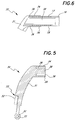
- Figure 5 is a front profile view of an end support.
- Figure 6 is a front profile view of an assembly including a partial front profile of an end support and a partial profile of a crossbar.
- Figure 7 is a side and partial sectional view of an assembly including an end support and pedestal, a guide, and wedges of a locking mechanism.
- Figure 8 is a perspective view of a guide.
- Figure 9 is a perspective view of forward and aft wedges.
- Figure 10 is a side profile view of a wedge bolt and an adjustment nut.
- Figure 11 is a perspective view of a lever and an eccentric shaft assembly.
- Figure 12 is an end view of the eccentric shaft depicted in Figure 11.
- the track mount system 10 comprises a pair of parallel disposed tracks 20 longitudinally mounted on a vehicle roof 12.
- a pair of gaskets 14 interpose the tracks 20 and the roof 12.
- a pair of end supports 30 are operably mounted on the tracks 20 and are interconnected by a crossbar 16.
- the end supports 30 are capable of traveling longitudinally along the tracks 20 and, when used in combination with a second assembly of the end supports 30 and the connecting crossbar 16, the end supports 30 and the crossbars 16 can be positioned along the track 20 to accommodate varying load sizes.
- Figure 4 shows a front profile view of an assembly comprising the track 20, the gasket 14, a guide 40, a pedestal 32, and a wedge bolt 70.
- the track 20 is preferably a straight extrusion, preferably extruded from a noncorrosive material such as aluminum or aluminum composite, with a track body 21 forming a substantially circular front profile.
- the track 20 extrusion is preferably sufficiently flexible to adapt to the longitudinal curvature of the vehicle roof 12.
- the body 21, however, is not a closed circle, rather it terminates at inwardly and angularly extending rails 23 and 24.
- the rails 23 and 24 extend inwardly at angles ⁇ and ⁇ , respectively, from the vertical V.
- the termination of the body 21 at the rails 23 and 24 forms an opening in the upper portion of the track 20.
- the angle ⁇ , along which the rail 23 is directed is preferably 10°-30°, most preferably substantially 22°, from the vertical V, while the angle ⁇ , along which the rail 24 is directed, is preferably 25°- 55°, most preferably substantially 45°, from the vertical V, thus creating a gap in the upper portion of the track body 21 that extends 35°-85°, most preferably substantially 67°, along the circumference of the track body 21.
- This configuration allows the end support 30 to rotate between the rails 23 and 24 through an angle of rotation of 35°-85°, most preferably substantially 67°, to compensate for the cross-line radius or fall-away slope of the vehicle roof 12, as the end supports 30 travel longitudinally along the tracks 20.
- the inner surface 22 of the track body 21 is preferably smooth to slidably receive a guide 40, discussed in more detail below.
- the guide 40 guides the pedestal 32 longitudinally along the track.
- Supporting the track body 21 is a pair of leg supports 25 and 26 that mount on the gasket 14.
- the leg support 25 is longer than the leg support 26 and is sloped at an angle ⁇ from the vertical V, while leg support 26 is also sloped at an angle ⁇ from the vertical V.
- the angles ⁇ and ⁇ are preferably 20° and 12°, respectively.
- This configuration of the leg supports 25 and 26 orients the opening of the track between the rails 23 and 24 such that the opening of the track 20 is tilted inwardly toward the longitudinal center line of the vehicle roof 12. This orientation tends to parallel the force vector that the track 20 is expected to experience during operation.
- This arrangement advantageously permits use of a substantially flat gasket 14.
- a substantially horizontal base 28 extends between leg supports 25 and 26.
- the base 28 is used to fasten the track 20 to the roof 12 of the vehicle.
- the heads of a fastener (not shown) used to fasten the track 20 to the vehicle roof 12 is easily recessed away from the track body 21 into a cavity formed by the base 28, the leg supports 25 and 26, and the body 21 of the track 20.
- an intermediate support 27 may optionally be added to extend vertically from the base 28 to the body 21 of the track 20.
- FIG. 1 An alternate track embodiment is shown in Figure 1.
- the track 20 in Figure 1 includes a circular body 21, rails 23 and 24, and leg supports 25 and 26 as in the previous embodiment.
- the lower end of the body 21 is used to fasten the track 20 to the vehicle roof 12.
- a gap is required to exist between the locking mechanism 50 and the lower end of the body 21 to prevent interference between a fastener head (not shown) and the locking mechanism 50 as the end support 30 slides longitudinally along the track 20.
- This arrangement provides an even lower profile for the track mount system 10.
- the end supports 30 comprise a substantially aerodynamic body 31 which is generally canted inwardly toward the center line of the vehicle roof 12.
- the upper portion of the body 31 forms a sleeve 34 and a stem 38, both extending away from the body 31 inwardly toward the longitudinal center line of the vehicle roof 12.
- the sleeve 34 and the stem 38 form a channel 36 therebetween that is adapted to receive an upper wall 17 and a lower wall 18 of the crossbar 16.
- the walls 17 and 18 of the crossbar 16 slide over the stem 38 and are slidably received within the channels 36, with the ends of walls 17 and 18 being hidden by the sleeves 34.
- the body 31, of the end support 30, extends downwardly to a substantially circular pedestal 32, as shown in Figure 5, that is rotatably received within the guide 40, discussed in detail in Figure 8.
- This configuration comprising a substantially circular pedestal 32 rotatably received within a guide 40 and a crossbar 16 slidably received within a sleeve 34 and channel 36 of an end support 30, allows the track mount system 10 to compensate for the cross-line radius or fall-away slope of the vehicle roof 12.
- the end support body 31 will tend to move inwardly and outwardly while rotating about its pedestal 32 as the cross-line radius or fall-away slope of the vehicle roof 12 changes.
- the track mount system 10 is able to maintain a low profile extending along the vehicle roof 12.
- the guide 40 has a substantially circular profile substantially similar to that of the track 20.
- the guide 40 preferably has a smooth outer surface 44 that allows it to slide longitudinally along the track 20 and a smooth inner surface 42 that allows rotation of the pedestal 32 within the guide 40.
- the substantially circular profile of the guide 40 terminates at edges 48.
- the edges 48 are angled inwardly to mate with the angled rails 23 and 24 of the track 20 shown in Figure 4.
- a retaining slot 46 is cut through the lower portion of the guide 40 and is used to retain the guide 40 on the pedestal 32.
- the guide 40 is attached to the forward portion 32a of the pedestal 32.
- Locking mechanism 50 preferably comprises forward and aft wedges 60 and 62, a wedge bolt 70, an adjustment nut 80, and an eccentric shaft 54 attached to a lever 52.
- the wedge bolt 70, adjustment nut 80, and lever 52 with eccentric shaft 54 are omitted from Figure 7 for clarity.
- the wedges 60 and 62, respectively, are oriented either forward and aft of a wedged pedestal 32 as shown in Figure 2, or simply aft of a pedestal 32 as shown in Figure 7.
- the wedge 60 is shown to be substantially cylindrical with a wedged or chamfered face 61.
- a bore hole 67 is bored into the non-chamfered end of the wedge 60, and enables the wedge 60 to mate with the aft end of the pedestal 32.
- a through-hole 66 passes through the wedge 60 from the wedged face 61 to the bore hole 67 and matches up with an identical through-hole 33 in the pedestal 32.
- a pair of opposing slots 64 and 65 extend the length of the upper portion of the wedge 60.
- the slots 64 and 65 are configured and adapted to receive the rails 23 and 24 of the track 20 shown in Figure 4, such that, upon full assembly of the track mount system 10, the wedge 60 is slidably received, and unable to rotate, within the track 20.
- the aft wedge 62 is similar to the forward wedge 60, wherein wedge 62 is also substantially cylindrical comprising identical slots 64 and 65 and mating oppositely-sloped wedge or chamfered face 63.
- the slots 64 and 65 of both wedges 60 and 62 enable the wedges 60 and 62 to be properly oriented within the track 20 such that the mating wedge faces 61 and 63 are properly aligned.
- a wedge bolt bore 68 is bored into the wedge 62 from the wedge face 63, and an adjustment nut through-hole 69 is drilled into the wedge 62 from the non-wedged faced end of the wedge 62 to intersect the wedge bolt bore 68.
- the wedge bolt 70 comprises a cylindrical head 72 that steps down to a cylindrical shaft 74 of smaller diameter.
- the shaft 74 is threaded at the end 75 opposite the head 72 end of the wedge bolt 70.
- An adjustment nut 80 is adapted to rotatably receive the threaded end 75 of the shaft 74.
- the head 72 When assembled, the head 72 is slidably received within a bore hole 35 in the forward portion 32a of the pedestal 32, while the shaft 74 extends through through-holes 33a and 33 of the pedestal 32, the bore 67 and through-hole 66 of the wedge 60, and bore 68 and through-hole 69 of wedge 62.
- the adjustment nut 80 is received within hole 69 and rotatably attaches to the shaft 74 at the threaded end 75 to adjust the wedges 60 and 62, respectively, locking the end supports 30 in place along the track 20.
- fine tune adjustment of the wedges 60 and 62 is accomplished by a device preferably utilizing a lever 52 and an eccentric shaft 54 assembly as shown in Figure 11.
- the eccentric shaft 54 extends from the cylindrical base 58 through a through-hole 39 in the forward pedestal 32a, a through-hole 76 in the head 72 of the wedge bolt 70, and on into the slot 46 of the guide 40. Rotation of the eccentric shaft 54 about its eccentric axis, shown in Figure 12, forces the wedge bolt 70 to move in a reciprocal motion.
- the shaft 54 also acts to retain the guide 40 on the pedestal 32a.
- the lever 52 is retained in operable connection with the end support 30 by a retaining pin (not shown) that is received within a bore 59 in the lever base 58 and a bore 37 in the end support body 31.
- a recess 53 in the body 31 of the end support 30 is adapted to receive a lever arm 56 to preserve the aerodynamic feature of the end support 30.
- the lever 52 with eccentric shaft 54, the wedge bolt 70, the guide 40, and the wedges 60 and 62, the guide 40, the pedestal 32, and the wedges 60 and 62 are slid into the track 20 while aligning the edges 48 of the guide 40 and the slots 64 and 65 of the wedges 60 and 62 with the rails 23 and 24 of the track 20.
- the adjustment nut 80 is screwed onto the threaded end 75 of the shaft 74. The adjustment nut 80 is adjusted until the wedges 60 and 62 are snug against one another and the track 20, but still in sliding communication with the track 20.
- the lever 52 can be moved to its locked position 52b, as shown in Figure 3, thus locking the end support 30 in place.
- the eccentric shaft 54 rotates within through-hole 76 of wedge bolt 70, further tensioning the wedge bolt 70 and pulling it toward the forward portion of the pedestal 32a.
- This generally longitudinal motion forces the wedges 60 and 62 against one another and to further move the wedges 60 and 62 longitudinally and transversely relative to one another along their respective faces 61 and 63.
- the wedge bore 68 allows the wedges 60 and 62 to move relative to one another without interference with the wedge bolt 70.
- the movement of the wedges 60 and 62 relative one another caused by moving the lever 50 from an unlocked 52a to a locked 52b position is sufficient to easily and effectively lock the end support 30 in a desired position along the track 20.
- FIG. 2 shows an alternate embodiment for the locking mechanism 50.
- the locking mechanism 50 similarly comprises forward and aft wedges 60 and 62, respectively, however, the wedge faces 61 and 63 are oriented as mirror images to one another.
- a pedestal 32 is wedge-shaped having a forward wedged faced 61a and an aft wedge faced 63a that mate with wedge faces 61 and 63, respectively, of the forward and aft wedges 60 and 62.
- the head 72 of the wedge bolt 70 is received within a bore in the forward wedge 60.
- the shaft 74 of the wedge bolt 72 extends through through-holes extending out of forward wedge 60 from the bore in the forward wedge 60, through the wedge pedestal 32 and through the aft wedge 62, wherein the adjustment nut 80 is able to screw onto the threaded end 75 of the shaft 74.
- the lever 52 is operably connected to the end support in similar fashion as described and illustrated in Figures 7 and 11.
- the eccentric shaft 54 extends down from the lever 52 into a bore in the forward wedge 60 retaining the forward wedge 60 in place, while passing through the through-hole 76 in the wedge bolt 70. As in the previous embodiment, rotation of the eccentric shaft 54 forces the wedge bolt 70 to move in a reciprocal motion.
- the forward and aft wedges 60 and 62 and the pedestal 32 are slid into the track.
- the forward and aft wedges 60 and 62 act as both guides to slide the end support 30 along the track 20 and brakes for a locking mechanism 50 to lock the end support 30 in place.
- the pedestal 32 is able to rotate about the wedge bolt 70 within the track.
- the pedestal 32 and the wedges 60 and 62 are slid into the track 20.
- the adjustment nut 80 is screwed onto the threaded end 75 of the shaft 74.
- the adjustment nut 80 is adjusted until the wedges 60 and 62 are snug against the pedestal 32 and the track 20, but still in sliding communication with the track 20.
- the lever 52 can be moved to its locked position 52b, as shown in Figure 3, thus locking the end support 30 in place.
- the eccentric shaft 54 rotates within through-hole 76 of the wedge bolt 70, further tensioning the wedge bolt 70 and pulling it toward the forward wedge 60.
- This generally longitudinal motion forces the wedges 60 and 62 against the pedestal 32 and to further move the wedges 60 and 62 longitudinally and transversely relative to the pedestal 32 along their respective faces 61, 63, 61a and 63a.
- the movement of the wedges 60 and 62 relative to the pedestal 32 caused by moving the lever 50 from an unlocked 52a to a locked 52b position is sufficient to easily and effectively lock the end support 30 in a position along the track 20.
Abstract
An adjustable article carrier track mount system that compensates for the cross-line radius or fall-away slope of a vehicle roof and easily and effectively locks the adjustable article carrier in place, has an elongated track, an end support operably connected to the track and adapted to slidably receive a crossbar, to slide longitudinally along the track, and rotate about the longitudinal axis of the track. To facilitate locking the adjustable article carrier in place, the track mount system includes a locking mechanism that is slidably received in the track and operably connected to the end support. The locking mechanism includes opposed wedges and a device adapted to force one of the wedges against another wedge to lock the locking mechanism within the track and thus the end support at a desired position along the track.
Description
- This invention relates to article carriers for automotive vehicles, specifically to an adjustable article carrier track mount system.
- Article carriers, commonly referred to as luggage racks, have long been utilized to carry loads on the exterior of automotive vehicles. The designs of these carriers have advanced from the purely functional rectangular configuration to the more aerodynamic and adjustable configurations.
- Adjustable carriers were developed to permit the user to adjust the carriers to the size of the load and provide additional securement. Typically in such assemblies, crossbar members are attached to end supports that are mounted on tracks longitudinally secured to the vehicle. End supports are allowed to travel longitudinally along the tracks varying the space between the crossbar members in accordance with the desired load size. Locking assemblies are provided to secure the end supports in the desired position along the tracks. With such a system, varying load sizes can be accommodated in a more secure fashion.
- However, the adjustable carrier systems of the past are not without shortcomings. For example, one of the disadvantages of these systems is that the tracks to which the end supports are mounted are rolled form steel. Although roll-form tracks are an effective means to accommodate the varying cross-car and longitudinal radii of different vehicle roof line designs, roll-forming results in a high-profile carrier. High-profile article carriers tend to reduce the aerodynamics and aesthetic value of the vehicle design. Moreover, the roll-forming of tracks to accommodate the wide variety of car designs has proven to be expensive and inefficient.
- Furthermore, the locking assemblies employed in these adjustable article carriers have been found to be unsatisfactory. Various locking assemblies have been utilized from nuts and bolts systems to lever and locking pin systems. However, these assemblies tend to be inconvenient to use, to induce unacceptable drag as the vehicle travels, or to ineffectively lock the end supports in place. Therefore, it would be desirable to have an adjustable article carrier with a low profile for greater aerodynamics and aesthetics, that is capable of compensating for the cross-line radius or fall-away slope of the vehicle roof, that is less expensive to produce and stock, that is convenient for the user to use, and that will easily and effectively lock the end supports in place while the vehicle is in motion.
- The track mount system of the present invention serves to facilitate compensation within an adjustable article carrier for the cross-line radius or fall-away slope of a vehicle roof, and easy and effective locking in place of an adjustable article carrier while the vehicle is in motion. It preferably has an elongated track and an end support operably connected to the track. The end support is adapted to slidably receive a crossbar and longitudinally slide along the track. In addition, the end support is able to rotate about a longitudinal axis of the track to compensate for the cross-line radius or fall-away slope of the vehicle roof.
- Preferably, the track mount system would include a locking mechanism operably connected to the end support and slidably received within the track. The locking mechanism includes opposed wedges and a device adapted to force one wedge against another wedge to lock the locking mechanism within the track, thus locking the end support in a desired position along the track.
- An object of this invention is to provide an improved track mount system for an adjustable article carrier.
- Further objects and advantages of the present invention will become apparent from consideration of the drawings and ensuing description.
- Figure 1 is a front profile view of the track mount system mounted to a vehicle roof.
- Figure 2 is a side view of a partial assembly of the track mount system including an end support, a lever with an eccentric shaft, a locking mechanism, and a track.
- Figure 3 is a top view of the track mount system assembly including a crossbar, an end support, a locking mechanism, a lever, and a track.
- Figure 4 is a front profile view of an assembly including a track, a gasket, a slide, a pedestal of an end support and a wedge bolt.
- Figure 5 is a front profile view of an end support.
- Figure 6 is a front profile view of an assembly including a partial front profile of an end support and a partial profile of a crossbar.
- Figure 7 is a side and partial sectional view of an assembly including an end support and pedestal, a guide, and wedges of a locking mechanism.
- Figure 8 is a perspective view of a guide.
- Figure 9 is a perspective view of forward and aft wedges.
- Figure 10 is a side profile view of a wedge bolt and an adjustment nut.
- Figure 11 is a perspective view of a lever and an eccentric shaft assembly.
- Figure 12 is an end view of the eccentric shaft depicted in Figure 11.
- Referring now in detail to the drawings, therein illustrated is a novel track mount system for a vehicle article carrier. As shown in Figure 1, the
track mount system 10 comprises a pair of parallel disposedtracks 20 longitudinally mounted on avehicle roof 12. A pair ofgaskets 14 interpose thetracks 20 and theroof 12. A pair ofend supports 30 are operably mounted on thetracks 20 and are interconnected by acrossbar 16. As shown in Figures 2 and 3, the end supports 30 are capable of traveling longitudinally along thetracks 20 and, when used in combination with a second assembly of the end supports 30 and the connectingcrossbar 16, the end supports 30 and thecrossbars 16 can be positioned along thetrack 20 to accommodate varying load sizes. - Figure 4 shows a front profile view of an assembly comprising the
track 20, thegasket 14, aguide 40, apedestal 32, and awedge bolt 70. Thetrack 20 is preferably a straight extrusion, preferably extruded from a noncorrosive material such as aluminum or aluminum composite, with atrack body 21 forming a substantially circular front profile. Thetrack 20 extrusion is preferably sufficiently flexible to adapt to the longitudinal curvature of thevehicle roof 12. Thebody 21, however, is not a closed circle, rather it terminates at inwardly and angularly extendingrails rails body 21 at therails track 20. The angle φ, along which therail 23 is directed, is preferably 10°-30°, most preferably substantially 22°, from the vertical V, while the angle θ, along which therail 24 is directed, is preferably 25°- 55°, most preferably substantially 45°, from the vertical V, thus creating a gap in the upper portion of thetrack body 21 that extends 35°-85°, most preferably substantially 67°, along the circumference of thetrack body 21. This configuration, as will be discussed in more detail later, allows theend support 30 to rotate between therails vehicle roof 12, as the end supports 30 travel longitudinally along thetracks 20. - The
inner surface 22 of thetrack body 21 is preferably smooth to slidably receive aguide 40, discussed in more detail below. Theguide 40 guides thepedestal 32 longitudinally along the track. - Supporting the
track body 21 is a pair of leg supports 25 and 26 that mount on thegasket 14. Theleg support 25 is longer than theleg support 26 and is sloped at an angle Ω from the vertical V, whileleg support 26 is also sloped at an angle τ from the vertical V. The angles Ω and τ are preferably 20° and 12°, respectively. This configuration of the leg supports 25 and 26 orients the opening of the track between therails track 20 is tilted inwardly toward the longitudinal center line of thevehicle roof 12. This orientation tends to parallel the force vector that thetrack 20 is expected to experience during operation. This arrangement advantageously permits use of a substantiallyflat gasket 14. - A substantially
horizontal base 28 extends between leg supports 25 and 26. Thebase 28 is used to fasten thetrack 20 to theroof 12 of the vehicle. The heads of a fastener (not shown) used to fasten thetrack 20 to thevehicle roof 12 is easily recessed away from thetrack body 21 into a cavity formed by thebase 28, the leg supports 25 and 26, and thebody 21 of thetrack 20. If further rigidity is desired, anintermediate support 27 may optionally be added to extend vertically from the base 28 to thebody 21 of thetrack 20. - An alternate track embodiment is shown in Figure 1. The
track 20 in Figure 1 includes acircular body 21, rails 23 and 24, and leg supports 25 and 26 as in the previous embodiment. The lower end of thebody 21 is used to fasten thetrack 20 to thevehicle roof 12. Thus, a gap is required to exist between the lockingmechanism 50 and the lower end of thebody 21 to prevent interference between a fastener head (not shown) and thelocking mechanism 50 as theend support 30 slides longitudinally along thetrack 20. This arrangement provides an even lower profile for thetrack mount system 10. - Referring to Figures 5, 6 and 7, the end supports 30 comprise a substantially
aerodynamic body 31 which is generally canted inwardly toward the center line of thevehicle roof 12. The upper portion of thebody 31 forms asleeve 34 and astem 38, both extending away from thebody 31 inwardly toward the longitudinal center line of thevehicle roof 12. Thesleeve 34 and thestem 38 form achannel 36 therebetween that is adapted to receive anupper wall 17 and alower wall 18 of thecrossbar 16. Thewalls crossbar 16 slide over thestem 38 and are slidably received within thechannels 36, with the ends ofwalls sleeves 34. In addition, thebody 31, of theend support 30, extends downwardly to a substantiallycircular pedestal 32, as shown in Figure 5, that is rotatably received within theguide 40, discussed in detail in Figure 8. This configuration, comprising a substantiallycircular pedestal 32 rotatably received within aguide 40 and acrossbar 16 slidably received within asleeve 34 andchannel 36 of anend support 30, allows thetrack mount system 10 to compensate for the cross-line radius or fall-away slope of thevehicle roof 12. Thus, as theend support 30 slides longitudinally along thetrack 20, theend support body 31 will tend to move inwardly and outwardly while rotating about itspedestal 32 as the cross-line radius or fall-away slope of thevehicle roof 12 changes. As this movement occurs, thewalls crossbar 16 slidably adjust over thestem 38 within thechannels 36, while remaining hidden by thesleeves 34. As a result of this method of cross-line radius or fall-away slope compensation, thetrack mount system 10 is able to maintain a low profile extending along thevehicle roof 12. - As shown in Figure 4, the
guide 40 has a substantially circular profile substantially similar to that of thetrack 20. Referring to Figure 8, theguide 40 preferably has a smoothouter surface 44 that allows it to slide longitudinally along thetrack 20 and a smoothinner surface 42 that allows rotation of thepedestal 32 within theguide 40. The substantially circular profile of theguide 40 terminates at edges 48. Theedges 48 are angled inwardly to mate with theangled rails track 20 shown in Figure 4. Preferably, a retainingslot 46 is cut through the lower portion of theguide 40 and is used to retain theguide 40 on thepedestal 32. In the embodiment illustrated in Figure 7, theguide 40 is attached to the forward portion 32a of thepedestal 32. - Referring to Figures 2 and 7, a
novel locking mechanism 50 of thetrack mount system 10 is therein illustrated. Lockingmechanism 50 preferably comprises forward andaft wedges wedge bolt 70, anadjustment nut 80, and aneccentric shaft 54 attached to alever 52. Thewedge bolt 70,adjustment nut 80, andlever 52 witheccentric shaft 54 are omitted from Figure 7 for clarity. Thewedges pedestal 32 as shown in Figure 2, or simply aft of apedestal 32 as shown in Figure 7. - Referring to Figures 7 and 9, the
wedge 60 is shown to be substantially cylindrical with a wedged or chamferedface 61. Abore hole 67 is bored into the non-chamfered end of thewedge 60, and enables thewedge 60 to mate with the aft end of thepedestal 32. A through-hole 66 passes through thewedge 60 from the wedgedface 61 to thebore hole 67 and matches up with an identical through-hole 33 in thepedestal 32. A pair of opposingslots wedge 60. Theslots rails track 20 shown in Figure 4, such that, upon full assembly of thetrack mount system 10, thewedge 60 is slidably received, and unable to rotate, within thetrack 20. - The
aft wedge 62 is similar to theforward wedge 60, whereinwedge 62 is also substantially cylindrical comprisingidentical slots face 63. Theslots wedges wedges track 20 such that the mating wedge faces 61 and 63 are properly aligned. In addition, a wedge bolt bore 68 is bored into thewedge 62 from thewedge face 63, and an adjustment nut through-hole 69 is drilled into thewedge 62 from the non-wedged faced end of thewedge 62 to intersect the wedge bolt bore 68. - Referring to Figure 10, the
wedge bolt 70 comprises acylindrical head 72 that steps down to acylindrical shaft 74 of smaller diameter. Theshaft 74 is threaded at theend 75 opposite thehead 72 end of thewedge bolt 70. Anadjustment nut 80 is adapted to rotatably receive the threadedend 75 of theshaft 74. - When assembled, the
head 72 is slidably received within abore hole 35 in the forward portion 32a of thepedestal 32, while theshaft 74 extends through through-holes 33a and 33 of thepedestal 32, thebore 67 and through-hole 66 of thewedge 60, and bore 68 and through-hole 69 ofwedge 62. Theadjustment nut 80 is received withinhole 69 and rotatably attaches to theshaft 74 at the threadedend 75 to adjust thewedges track 20. - However, fine tune adjustment of the
wedges lever 52 and aneccentric shaft 54 assembly as shown in Figure 11. Theeccentric shaft 54 extends from thecylindrical base 58 through a through-hole 39 in the forward pedestal 32a, a through-hole 76 in thehead 72 of thewedge bolt 70, and on into theslot 46 of theguide 40. Rotation of theeccentric shaft 54 about its eccentric axis, shown in Figure 12, forces thewedge bolt 70 to move in a reciprocal motion. Theshaft 54 also acts to retain theguide 40 on the pedestal 32a. Thelever 52 is retained in operable connection with theend support 30 by a retaining pin (not shown) that is received within abore 59 in thelever base 58 and abore 37 in theend support body 31. Arecess 53 in thebody 31 of theend support 30 is adapted to receive alever arm 56 to preserve the aerodynamic feature of theend support 30. - In operation, after assembly of the
end support 30, thelever 52 witheccentric shaft 54, thewedge bolt 70, theguide 40, and thewedges guide 40, thepedestal 32, and thewedges track 20 while aligning theedges 48 of theguide 40 and theslots wedges rails track 20. With the assembly slidably received in thetrack 20 and thelever 52 in an unlocked position 52a, as shown in Figure 3, theadjustment nut 80 is screwed onto the threadedend 75 of theshaft 74. Theadjustment nut 80 is adjusted until thewedges track 20, but still in sliding communication with thetrack 20. After sliding theend support 30 to a desired position along thetrack 20, thelever 52 can be moved to its locked position 52b, as shown in Figure 3, thus locking theend support 30 in place. As thelever 52 moves from its unlocked position 52a to its locked position of 52b, theeccentric shaft 54 rotates within through-hole 76 ofwedge bolt 70, further tensioning thewedge bolt 70 and pulling it toward the forward portion of the pedestal 32a. This generally longitudinal motion forces thewedges wedges respective faces wedges wedge bolt 70. The movement of thewedges lever 50 from an unlocked 52a to a locked 52b position is sufficient to easily and effectively lock theend support 30 in a desired position along thetrack 20. - As noted above, Figure 2 shows an alternate embodiment for the
locking mechanism 50. Thelocking mechanism 50 similarly comprises forward andaft wedges pedestal 32 is wedge-shaped having a forward wedged faced 61a and an aft wedge faced 63a that mate with wedge faces 61 and 63, respectively, of the forward andaft wedges head 72 of thewedge bolt 70 is received within a bore in theforward wedge 60. Theshaft 74 of thewedge bolt 72 extends through through-holes extending out offorward wedge 60 from the bore in theforward wedge 60, through thewedge pedestal 32 and through theaft wedge 62, wherein theadjustment nut 80 is able to screw onto the threadedend 75 of theshaft 74. Thelever 52 is operably connected to the end support in similar fashion as described and illustrated in Figures 7 and 11. Theeccentric shaft 54 extends down from thelever 52 into a bore in theforward wedge 60 retaining theforward wedge 60 in place, while passing through the through-hole 76 in thewedge bolt 70. As in the previous embodiment, rotation of theeccentric shaft 54 forces thewedge bolt 70 to move in a reciprocal motion. - After assembly of the
end support 30 withpedestal 32, the forward andaft wedges wedge bolt 70, thelever 52 witheccentric shaft 54, and theadjustment nut 80, the forward andaft wedges pedestal 32 are slid into the track. The forward andaft wedges end support 30 along thetrack 20 and brakes for alocking mechanism 50 to lock theend support 30 in place. Thepedestal 32 is able to rotate about thewedge bolt 70 within the track. Thus, this configuration provides aneffective locking mechanism 50 along with the capability of compensating for the cross-line radius or fall-away slope of thevehicle roof 12 by allowing rotation of the end supports 30 via itspedestal 32 about thewedge bolt 70. - In operation, after assembly of the
end support 30 with thepedestal 32, thelever 52 with theeccentric shaft 54, thewedge bolt 70, and thewedges pedestal 32 and thewedges track 20. With the assembly slidably received in thetrack 20 and thelever 52 in an unlocked position 52a, as shown in Figure 3, theadjustment nut 80 is screwed onto the threadedend 75 of theshaft 74. Theadjustment nut 80 is adjusted until thewedges pedestal 32 and thetrack 20, but still in sliding communication with thetrack 20. After sliding theend support 30 to a desired position along thetrack 20, thelever 52 can be moved to its locked position 52b, as shown in Figure 3, thus locking theend support 30 in place. As thelever 52 moves from its unlocked position 52a to its locked position 52b, theeccentric shaft 54 rotates within through-hole 76 of thewedge bolt 70, further tensioning thewedge bolt 70 and pulling it toward theforward wedge 60. This generally longitudinal motion forces thewedges pedestal 32 and to further move thewedges pedestal 32 along theirrespective faces wedges pedestal 32 caused by moving thelever 50 from an unlocked 52a to a locked 52b position is sufficient to easily and effectively lock theend support 30 in a position along thetrack 20. - Although it is preferred to lock the
end support 30 in place along thetrack 20 by tensioning thewedge bolt 70 to drawaft wedge 62 forward, a structurally equivalent device can be used to push theaft wedge 62 forward. Such a device would essentially accomplish the desired effect of the previous embodiments of locking theend support 30 in place along thetrack 20. - While the above description contains many specifics, these should not be construed as limitations on the scope of the invention, but rather as an example of the preferred embodiments thereof. Many other variations are possible. Accordingly, the scope of the present invention should be determined not by the embodiments illustrated above, but by the appended claims and their legal equivalents.
Claims (12)
- A track mount system for a vehicle carrier comprising
an elongated track,
an end support operably connected to said track and adapted to slide longitudinally along said track, and
a locking mechanism slidably retained within said track and operably connected to said end support, said locking mechanism including
first and second opposed wedges, and
a device operably connected to said first and second opposed wedges to force said second wedge against said first wedge, said device including a tensioning bolt extending from said first wedge through said second wedge. - The track mount system of Claim 1, further comprising an adjustment nut adjustably attached to a threaded end of said tensioning bolt.
- A track mount system for a vehicle carrier comprising
an elongated track,
an end support operably connected to said track and adapted to slide longitudinally along said track, and
a locking mechanism slidably retained within said track and operably connected to said end support, said locking mechanism including
first and second opposed wedges,
a lever operably connected to said end support,
a rod extending from said lever, and
a tensioning bolt operably connected to said first and second opposed wedges and said rod, said bolt drawing said second wedge against said first wedge as said lever is moved from a first position to a second position. - A track mount system for a vehicle carrier comprising
an elongated track,
a guide slidably retained within said track,
an end support adapted to slidably receive a crossbar, and
a pedestal extending from said end support into said track and rotatably connecting to said guide to compensate for the fall-away slope of a vehicle roof as said guide and said pedestal slide longitudinally along said track. - The track mount system of Claim 4, wherein said track is a substantially flexible and a substantially straight extrusion.
- The track mount system of Claim 4, wherein said track, said guide and said pedestal have substantially circular profiles.
- The track mount system of Claim 4, further comprising a forward wedge and an aft wedge operable connected to said pedestal and slidably retained within said track.
- The track mount system of Claim 7, further comprising a rail angularly extending inwardly from said track and operably connecting to said forward and aft wedges.
- A track mount system for a vehicle carrier comprising
an elongated track,
a guide slidably retained within said track,
an end support adapted to slidably receive a crossbar,
a pedestal extending from said end support into said track and rotatably connecting to said guide to compensate for the fall-away slope of a vehicle roof as said guide and said pedestal slide longitudinally along said track, and
a locking mechanism slidably retained within said track and operably connected to said end support, said locking mechanism including
first and second opposed wedges, and
a device operably connected to said first and second wedges to force said second wedge against said first wedge to lock said end support in a locked position along said track. - The track mount system of Claim 9, wherein said device of said locking mechanism further comprises an eccentric shaft operably connected to said first and second wedges.
- The track mount system of Claim 10, further comprising a lever attached to said eccentric shaft.
- The track mount system of Claim 9, wherein said device further comprises a tensioning bolt extending from said first wedge through said second wedge.
Applications Claiming Priority (2)
| Application Number | Priority Date | Filing Date | Title |
|---|---|---|---|
| US333003 | 1981-12-21 | ||
| US08/333,003 US5551617A (en) | 1994-11-01 | 1994-11-01 | Track mount system |
Publications (2)
| Publication Number | Publication Date |
|---|---|
| EP0710586A2 true EP0710586A2 (en) | 1996-05-08 |
| EP0710586A3 EP0710586A3 (en) | 1996-05-29 |
Family
ID=23300838
Family Applications (1)
| Application Number | Title | Priority Date | Filing Date |
|---|---|---|---|
| EP95116965A Withdrawn EP0710586A2 (en) | 1994-11-01 | 1995-10-27 | Track mount system for vehicle carrier |
Country Status (2)
| Country | Link |
|---|---|
| US (2) | US5551617A (en) |
| EP (1) | EP0710586A2 (en) |
Cited By (2)
| Publication number | Priority date | Publication date | Assignee | Title |
|---|---|---|---|---|
| CN109131113A (en) * | 2018-10-12 | 2019-01-04 | 周丰 | A kind of vehicle roof rack |
| RU216690U1 (en) * | 2022-05-27 | 2023-02-21 | Индивидуальный предприниматель Пикунов Артём Арнольдович | ROOF RACK SUPPORT |
Families Citing this family (9)
| Publication number | Priority date | Publication date | Assignee | Title |
|---|---|---|---|---|
| DE19858558B4 (en) * | 1998-12-18 | 2006-04-13 | Jac Products Deutschland Gmbh | Roof rail for vehicles |
| US6305589B1 (en) * | 1999-03-01 | 2001-10-23 | Industri Ab Thule | Vertically engageable carrier foot |
| USD434364S (en) * | 1999-07-09 | 2000-11-28 | Nissan Design International, Inc. | Vehicle roof rack |
| US6561397B1 (en) | 1999-07-09 | 2003-05-13 | Nissan Design America, Inc. | Vehicle roof rack system |
| DE10210141A1 (en) * | 2002-03-07 | 2003-09-18 | Arvinmeritor Gmbh | Body part and method for its production |
| FR2884198B3 (en) * | 2005-04-12 | 2008-11-07 | Scambia Ind Dev Ag | BAR FOR FIXING ON A ROOF OF A MOTOR VEHICLE |
| CZ2006272A3 (en) * | 2006-04-26 | 2007-11-07 | Ac Lak, S.R.O. | Vehicle roof luggage carrier |
| EP3013647B1 (en) * | 2013-06-24 | 2018-05-23 | Mont Blanc Industri AB | A support foot for luggage carrier |
| US10040403B2 (en) * | 2015-06-09 | 2018-08-07 | Yakima Products, Inc. | Crossbar clamp actuator |
Family Cites Families (53)
| Publication number | Priority date | Publication date | Assignee | Title |
|---|---|---|---|---|
| US3223301A (en) * | 1962-05-24 | 1965-12-14 | Helm Accessories Inc | Car top carrier |
| US3253755A (en) * | 1964-06-22 | 1966-05-31 | John A Bott | Luggage rack |
| US3325067A (en) * | 1965-04-12 | 1967-06-13 | Helm Design & Mfg Inc | Car top luggage carrier |
| US3554416A (en) * | 1968-02-21 | 1971-01-12 | Bott John Anthony | Vehicle luggage rack |
| US4182471A (en) * | 1974-07-08 | 1980-01-08 | Bott John Anthony | Article carrier for automotive vehicles |
| US4516710A (en) * | 1974-07-08 | 1985-05-14 | Bott John Anthony | Article carrier for automotive vehicles |
| US4099658A (en) * | 1974-07-08 | 1978-07-11 | Bott John Anthony | Article carrier for automotive vehicles |
| US4440333A (en) * | 1974-07-08 | 1984-04-03 | Bott John Anthony | Article carrier for automotive vehicles |
| US4047689A (en) * | 1976-07-19 | 1977-09-13 | Uop Inc. | Load distributing track fitting |
| US4101061A (en) * | 1977-05-09 | 1978-07-18 | U-Haul International, Inc. | Adjustable car top carrier support |
| US4132335A (en) * | 1977-09-27 | 1979-01-02 | Four Star Corporation | Slidable bracket for article carrier |
| US4270681A (en) * | 1977-09-27 | 1981-06-02 | Four Star Corporation | Slidable bracket for article carrier |
| US4323182A (en) * | 1977-10-27 | 1982-04-06 | Bott John Anthony | Luggage carrier assembly |
| US4185799A (en) * | 1978-03-14 | 1980-01-29 | Boeing Commercial Airplane Company | Aircraft partition mounting assembly |
| US4244501A (en) * | 1979-01-18 | 1981-01-13 | Four Star Corporation | Slidable bracket for luggage rack |
| US4264025A (en) * | 1979-02-26 | 1981-04-28 | Four Star Corporation | Tiedown bracket with ratchet disc |
| US4279368A (en) * | 1979-03-09 | 1981-07-21 | Four Star Corporation | Stanchion assembly |
| US4372469A (en) * | 1979-03-29 | 1983-02-08 | Four Star Corporation | Article carrier having variably positionable cross-rail bracket |
| US4245764A (en) * | 1979-03-29 | 1981-01-20 | Four Star Corporation | Article carrier having variably positionable cross-rail bracket |
| US4278376A (en) * | 1979-06-11 | 1981-07-14 | Hunter Mike E | Load restraining panel |
| US4239138A (en) * | 1979-06-11 | 1980-12-16 | Four Star Corporation | Article carrier comprising slotted side rail with slidable cross-rail and bracket therefor |
| US4295588A (en) * | 1979-09-04 | 1981-10-20 | Four Star Corporation | Slotted side rail and movable bracket for article carrier |
| US4269340A (en) * | 1979-09-28 | 1981-05-26 | Four Star Corporation | Load bearing cross-slat |
| US4826061A (en) * | 1979-10-29 | 1989-05-02 | Amco Manufacturing Corporation | Vehicle luggage carrier with flush tiedown endcap |
| US4815643A (en) * | 1979-10-29 | 1989-03-28 | Amco Manufacturing Corporation | Modular luggage carrier with sliding tie-down bracket stabilized against luggage securing forces |
| US4616771A (en) * | 1979-10-29 | 1986-10-14 | Amco Manufacturing Corporation | Modular luggage rack with accessories |
| CA1183819A (en) * | 1980-07-23 | 1985-03-12 | John A. Bott | Cross rail for vehicle luggage carrier |
| US4341332A (en) * | 1980-12-29 | 1982-07-27 | Four Star Corporation | Stanchion assembly |
| US4473178A (en) * | 1981-02-27 | 1984-09-25 | Bott John Anthony | Vehicle luggage carrier |
| US4406386A (en) * | 1981-04-06 | 1983-09-27 | Masco Corporation | Article carrier and a bracket therefor |
| US4487348A (en) * | 1981-10-15 | 1984-12-11 | Four Star Corporation | Adjustable and removable cross rail |
| US4500020A (en) * | 1982-05-06 | 1985-02-19 | Masco Corp. | Article carrier with adjustably positionable bracket |
| US4469261A (en) * | 1982-05-06 | 1984-09-04 | Masco Corporation | Article carrier with adjustably positionable bracket |
| US4448337A (en) * | 1982-05-06 | 1984-05-15 | Masco Corporation | Article carrier |
| US4588117A (en) * | 1983-04-11 | 1986-05-13 | Bott John Anthony | Cross rail for vehicle luggage carrier |
| US4684048A (en) * | 1985-09-20 | 1987-08-04 | Bott John Anthony | Vehicle article carrier |
| DE3614740A1 (en) * | 1986-04-30 | 1987-11-05 | Bayerische Motoren Werke Ag | Roofrack fastening on a vehicle roof |
| US4768692A (en) * | 1986-07-28 | 1988-09-06 | Four Star Corporation | End cap and tie down assembly for article carrier |
| US4768691A (en) * | 1986-09-22 | 1988-09-06 | Huron/St. Clair Company, A Division Of Masco Industries, Inc. | Adjustable support rail for a luggage carrier |
| KR910005299B1 (en) * | 1987-03-03 | 1991-07-24 | 마쯔다 가부시기가이샤 | Structure for mounting roof carriers on a roof of motorcar |
| US4765522A (en) * | 1987-03-06 | 1988-08-23 | Oliver Industries, Inc. | Luggage carrier |
| US4911348A (en) * | 1988-05-03 | 1990-03-27 | Huron/St. Clair Company | Adjustable cross rail for luggage carrier |
| US4982886A (en) * | 1989-03-27 | 1991-01-08 | John A. Bott | Article carrier |
| US4988026A (en) * | 1989-05-15 | 1991-01-29 | Huron/St. Clair Incorporated | Discretely adjustable support rail for luggage carriers |
| US5004139A (en) * | 1989-09-15 | 1991-04-02 | Hagus, U.S.A., Inc. | Vehicle article holder |
| US5007570A (en) * | 1990-04-02 | 1991-04-16 | Chrysler Corporation | Luggage rack for a vehicle |
| US5016798A (en) * | 1990-04-05 | 1991-05-21 | Huron/St. Clair Incorporated | Spacer insert for load-bearing slats |
| US5170920A (en) * | 1991-02-15 | 1992-12-15 | Masco Corporation | Luggage rack |
| SE469220B (en) * | 1992-06-24 | 1993-06-07 | Thule Ind Ab | RELAY DEVICE |
| WO1994010007A1 (en) * | 1992-10-28 | 1994-05-11 | The American Team | Carrier operable from one side of vehicle |
| US5320264A (en) * | 1993-01-11 | 1994-06-14 | Perrycraft, Inc. | Adjustable vehicle cargo carrier construction |
| SE501055C2 (en) * | 1993-03-24 | 1994-10-31 | Thule Ind Ab | load carriers |
| WO1995010007A1 (en) * | 1993-10-06 | 1995-04-13 | Hdg Entwicklungs- Und Patentverwertungsges. Mbh | Method and device for controlling the consumption of solid fuels in a combustion unit |
-
1994
- 1994-11-01 US US08/333,003 patent/US5551617A/en not_active Expired - Fee Related
-
1995
- 1995-10-27 EP EP95116965A patent/EP0710586A2/en not_active Withdrawn
-
1996
- 1996-08-19 US US08/699,170 patent/US5839615A/en not_active Expired - Fee Related
Non-Patent Citations (1)
| Title |
|---|
| None |
Cited By (2)
| Publication number | Priority date | Publication date | Assignee | Title |
|---|---|---|---|---|
| CN109131113A (en) * | 2018-10-12 | 2019-01-04 | 周丰 | A kind of vehicle roof rack |
| RU216690U1 (en) * | 2022-05-27 | 2023-02-21 | Индивидуальный предприниматель Пикунов Артём Арнольдович | ROOF RACK SUPPORT |
Also Published As
| Publication number | Publication date |
|---|---|
| US5839615A (en) | 1998-11-24 |
| US5551617A (en) | 1996-09-03 |
| EP0710586A3 (en) | 1996-05-29 |
Similar Documents
| Publication | Publication Date | Title |
|---|---|---|
| US11225200B2 (en) | Vehicular rack having modular design with outside handle and quick release | |
| US5551617A (en) | Track mount system | |
| US5470003A (en) | Adjustable cross rail for a vehicle article carrier | |
| US5393114A (en) | Reversible utility rail and utility rack | |
| US4900217A (en) | Stowable, multiple grade ramping device | |
| US7214018B2 (en) | Sliding bed accessory arrangement | |
| US5342013A (en) | Seat sliding device for vehicle | |
| US7159918B2 (en) | Sliding bed extender arrangement | |
| EP0872381A2 (en) | Fastening device for a roof rack | |
| US4988026A (en) | Discretely adjustable support rail for luggage carriers | |
| US6520393B1 (en) | Tiltable rooftop cargo carrier for a vehicle | |
| US20040118886A1 (en) | Apparatus and methods for securing a crossbar to a roof rack | |
| CN113291222B (en) | Multipurpose transport vehicle | |
| US20030230697A1 (en) | Pivotable clamp | |
| US20130015221A1 (en) | Adjustable hi-low hitch mounted cargo carrier | |
| WO1995006800A1 (en) | Arrangement for mounting slides | |
| US5221103A (en) | Quick change slider panel and installation method for flatbed trailer | |
| DE19819011B4 (en) | Adjustable holding device for on-board computers in motor vehicles, in particular for laptop or notebook computers | |
| GB2228453A (en) | Stowable bulkhead for vehicle body | |
| US20230234648A1 (en) | Twist lock accessory rack system | |
| JP2001071820A (en) | Vehicular article carrier device with adjustable non- fixed cross bar | |
| US5531367A (en) | Vehicle baggage-holder device | |
| US20030155390A1 (en) | Adjustable hitch mounted cargo carrier | |
| GB2275296A (en) | A clampable carriage sliding on a track. | |
| US11945410B2 (en) | Ladder rack system |
Legal Events
| Date | Code | Title | Description |
|---|---|---|---|
| PUAI | Public reference made under article 153(3) epc to a published international application that has entered the european phase |
Free format text: ORIGINAL CODE: 0009012 |
|
| PUAL | Search report despatched |
Free format text: ORIGINAL CODE: 0009013 |
|
| AK | Designated contracting states |
Kind code of ref document: A2 Designated state(s): AT BE CH DE DK ES FR GB GR IE IT LI LU MC NL PT SE |
|
| AK | Designated contracting states |
Kind code of ref document: A3 Designated state(s): AT BE CH DE DK ES FR GB GR IE IT LI LU MC NL PT SE |
|
| STAA | Information on the status of an ep patent application or granted ep patent |
Free format text: STATUS: THE APPLICATION IS DEEMED TO BE WITHDRAWN |
|
| 18D | Application deemed to be withdrawn |
Effective date: 19961130 |