EP0710562B1 - Printer - Google Patents
Printer Download PDFInfo
- Publication number
- EP0710562B1 EP0710562B1 EP95307890A EP95307890A EP0710562B1 EP 0710562 B1 EP0710562 B1 EP 0710562B1 EP 95307890 A EP95307890 A EP 95307890A EP 95307890 A EP95307890 A EP 95307890A EP 0710562 B1 EP0710562 B1 EP 0710562B1
- Authority
- EP
- European Patent Office
- Prior art keywords
- printhead
- signal
- pulse
- printing
- Prior art date
- Legal status (The legal status is an assumption and is not a legal conclusion. Google has not performed a legal analysis and makes no representation as to the accuracy of the status listed.)
- Expired - Lifetime
Links
- 238000007639 printing Methods 0.000 claims description 131
- 230000036278 prepulse Effects 0.000 claims description 82
- 238000000034 method Methods 0.000 claims description 31
- 238000007599 discharging Methods 0.000 claims description 15
- 230000005611 electricity Effects 0.000 claims description 13
- 238000010438 heat treatment Methods 0.000 claims description 10
- 238000012544 monitoring process Methods 0.000 claims description 8
- 238000009529 body temperature measurement Methods 0.000 claims description 4
- 230000002401 inhibitory effect Effects 0.000 claims 2
- 230000005764 inhibitory process Effects 0.000 claims 2
- 239000000976 ink Substances 0.000 description 95
- 238000012546 transfer Methods 0.000 description 38
- 238000010926 purge Methods 0.000 description 25
- 238000010586 diagram Methods 0.000 description 22
- 239000003086 colorant Substances 0.000 description 19
- 230000006870 function Effects 0.000 description 14
- 230000008859 change Effects 0.000 description 12
- 239000007788 liquid Substances 0.000 description 12
- 102100027152 Dihydrolipoyllysine-residue acetyltransferase component of pyruvate dehydrogenase complex, mitochondrial Human genes 0.000 description 11
- 101001122360 Homo sapiens Dihydrolipoyllysine-residue acetyltransferase component of pyruvate dehydrogenase complex, mitochondrial Proteins 0.000 description 11
- 238000011084 recovery Methods 0.000 description 9
- 230000007613 environmental effect Effects 0.000 description 6
- 239000000758 substrate Substances 0.000 description 6
- 101100314162 Candida albicans (strain SC5314 / ATCC MYA-2876) YBL053 gene Proteins 0.000 description 4
- 230000002159 abnormal effect Effects 0.000 description 4
- 238000004140 cleaning Methods 0.000 description 4
- 238000004891 communication Methods 0.000 description 4
- 238000001816 cooling Methods 0.000 description 4
- 230000004044 response Effects 0.000 description 4
- 239000007787 solid Substances 0.000 description 4
- 101150044955 tof1 gene Proteins 0.000 description 4
- 230000005540 biological transmission Effects 0.000 description 3
- 238000009835 boiling Methods 0.000 description 3
- 238000012937 correction Methods 0.000 description 3
- 230000000694 effects Effects 0.000 description 3
- 238000004519 manufacturing process Methods 0.000 description 3
- -1 DIK1 Proteins 0.000 description 2
- 101000928408 Homo sapiens Protein diaphanous homolog 2 Proteins 0.000 description 2
- 102100036469 Protein diaphanous homolog 2 Human genes 0.000 description 2
- 230000003247 decreasing effect Effects 0.000 description 2
- 230000003111 delayed effect Effects 0.000 description 2
- 238000001514 detection method Methods 0.000 description 2
- 230000006866 deterioration Effects 0.000 description 2
- 230000008569 process Effects 0.000 description 2
- 230000009467 reduction Effects 0.000 description 2
- 230000003252 repetitive effect Effects 0.000 description 2
- CJOXJJYSFBAIOV-WMZJFQQLSA-N (z)-4-(5-chloro-1h-indol-3-yl)-4-hydroxy-2-oxobut-3-enoic acid Chemical compound C1=C(Cl)C=C2C(C(/O)=C/C(=O)C(=O)O)=CNC2=C1 CJOXJJYSFBAIOV-WMZJFQQLSA-N 0.000 description 1
- 101100391178 Dictyostelium discoideum forE gene Proteins 0.000 description 1
- 101100476085 Dictyostelium discoideum mrps4 gene Proteins 0.000 description 1
- 101100030422 Saccharomyces cerevisiae (strain ATCC 204508 / S288c) DIA3 gene Proteins 0.000 description 1
- 101100275670 Saccharomyces cerevisiae (strain ATCC 204508 / S288c) TFS1 gene Proteins 0.000 description 1
- 101100370021 Saccharomyces cerevisiae (strain ATCC 204508 / S288c) TOF2 gene Proteins 0.000 description 1
- 241000610628 Trichoptilium incisum Species 0.000 description 1
- 238000005520 cutting process Methods 0.000 description 1
- 230000007423 decrease Effects 0.000 description 1
- 230000001419 dependent effect Effects 0.000 description 1
- 230000002542 deteriorative effect Effects 0.000 description 1
- 239000000428 dust Substances 0.000 description 1
- 238000001704 evaporation Methods 0.000 description 1
- 230000008020 evaporation Effects 0.000 description 1
- 230000020169 heat generation Effects 0.000 description 1
- 230000010365 information processing Effects 0.000 description 1
- 238000007641 inkjet printing Methods 0.000 description 1
- 230000007246 mechanism Effects 0.000 description 1
- 230000006386 memory function Effects 0.000 description 1
- 238000003672 processing method Methods 0.000 description 1
- 239000004065 semiconductor Substances 0.000 description 1
- 230000001360 synchronised effect Effects 0.000 description 1
- 238000012360 testing method Methods 0.000 description 1
- 238000003079 width control Methods 0.000 description 1
Images











Classifications
-
- B—PERFORMING OPERATIONS; TRANSPORTING
- B41—PRINTING; LINING MACHINES; TYPEWRITERS; STAMPS
- B41J—TYPEWRITERS; SELECTIVE PRINTING MECHANISMS, i.e. MECHANISMS PRINTING OTHERWISE THAN FROM A FORME; CORRECTION OF TYPOGRAPHICAL ERRORS
- B41J2/00—Typewriters or selective printing mechanisms characterised by the printing or marking process for which they are designed
- B41J2/005—Typewriters or selective printing mechanisms characterised by the printing or marking process for which they are designed characterised by bringing liquid or particles selectively into contact with a printing material
- B41J2/01—Ink jet
- B41J2/015—Ink jet characterised by the jet generation process
- B41J2/04—Ink jet characterised by the jet generation process generating single droplets or particles on demand
- B41J2/045—Ink jet characterised by the jet generation process generating single droplets or particles on demand by pressure, e.g. electromechanical transducers
- B41J2/04501—Control methods or devices therefor, e.g. driver circuits, control circuits
- B41J2/04528—Control methods or devices therefor, e.g. driver circuits, control circuits aiming at warming up the head
-
- B—PERFORMING OPERATIONS; TRANSPORTING
- B41—PRINTING; LINING MACHINES; TYPEWRITERS; STAMPS
- B41J—TYPEWRITERS; SELECTIVE PRINTING MECHANISMS, i.e. MECHANISMS PRINTING OTHERWISE THAN FROM A FORME; CORRECTION OF TYPOGRAPHICAL ERRORS
- B41J2/00—Typewriters or selective printing mechanisms characterised by the printing or marking process for which they are designed
- B41J2/005—Typewriters or selective printing mechanisms characterised by the printing or marking process for which they are designed characterised by bringing liquid or particles selectively into contact with a printing material
- B41J2/01—Ink jet
- B41J2/015—Ink jet characterised by the jet generation process
- B41J2/04—Ink jet characterised by the jet generation process generating single droplets or particles on demand
- B41J2/045—Ink jet characterised by the jet generation process generating single droplets or particles on demand by pressure, e.g. electromechanical transducers
- B41J2/04501—Control methods or devices therefor, e.g. driver circuits, control circuits
- B41J2/04541—Specific driving circuit
-
- B—PERFORMING OPERATIONS; TRANSPORTING
- B41—PRINTING; LINING MACHINES; TYPEWRITERS; STAMPS
- B41J—TYPEWRITERS; SELECTIVE PRINTING MECHANISMS, i.e. MECHANISMS PRINTING OTHERWISE THAN FROM A FORME; CORRECTION OF TYPOGRAPHICAL ERRORS
- B41J2/00—Typewriters or selective printing mechanisms characterised by the printing or marking process for which they are designed
- B41J2/005—Typewriters or selective printing mechanisms characterised by the printing or marking process for which they are designed characterised by bringing liquid or particles selectively into contact with a printing material
- B41J2/01—Ink jet
- B41J2/015—Ink jet characterised by the jet generation process
- B41J2/04—Ink jet characterised by the jet generation process generating single droplets or particles on demand
- B41J2/045—Ink jet characterised by the jet generation process generating single droplets or particles on demand by pressure, e.g. electromechanical transducers
- B41J2/04501—Control methods or devices therefor, e.g. driver circuits, control circuits
- B41J2/04543—Block driving
-
- B—PERFORMING OPERATIONS; TRANSPORTING
- B41—PRINTING; LINING MACHINES; TYPEWRITERS; STAMPS
- B41J—TYPEWRITERS; SELECTIVE PRINTING MECHANISMS, i.e. MECHANISMS PRINTING OTHERWISE THAN FROM A FORME; CORRECTION OF TYPOGRAPHICAL ERRORS
- B41J2/00—Typewriters or selective printing mechanisms characterised by the printing or marking process for which they are designed
- B41J2/005—Typewriters or selective printing mechanisms characterised by the printing or marking process for which they are designed characterised by bringing liquid or particles selectively into contact with a printing material
- B41J2/01—Ink jet
- B41J2/015—Ink jet characterised by the jet generation process
- B41J2/04—Ink jet characterised by the jet generation process generating single droplets or particles on demand
- B41J2/045—Ink jet characterised by the jet generation process generating single droplets or particles on demand by pressure, e.g. electromechanical transducers
- B41J2/04501—Control methods or devices therefor, e.g. driver circuits, control circuits
- B41J2/04563—Control methods or devices therefor, e.g. driver circuits, control circuits detecting head temperature; Ink temperature
-
- B—PERFORMING OPERATIONS; TRANSPORTING
- B41—PRINTING; LINING MACHINES; TYPEWRITERS; STAMPS
- B41J—TYPEWRITERS; SELECTIVE PRINTING MECHANISMS, i.e. MECHANISMS PRINTING OTHERWISE THAN FROM A FORME; CORRECTION OF TYPOGRAPHICAL ERRORS
- B41J2/00—Typewriters or selective printing mechanisms characterised by the printing or marking process for which they are designed
- B41J2/005—Typewriters or selective printing mechanisms characterised by the printing or marking process for which they are designed characterised by bringing liquid or particles selectively into contact with a printing material
- B41J2/01—Ink jet
- B41J2/015—Ink jet characterised by the jet generation process
- B41J2/04—Ink jet characterised by the jet generation process generating single droplets or particles on demand
- B41J2/045—Ink jet characterised by the jet generation process generating single droplets or particles on demand by pressure, e.g. electromechanical transducers
- B41J2/04501—Control methods or devices therefor, e.g. driver circuits, control circuits
- B41J2/0458—Control methods or devices therefor, e.g. driver circuits, control circuits controlling heads based on heating elements forming bubbles
-
- B—PERFORMING OPERATIONS; TRANSPORTING
- B41—PRINTING; LINING MACHINES; TYPEWRITERS; STAMPS
- B41J—TYPEWRITERS; SELECTIVE PRINTING MECHANISMS, i.e. MECHANISMS PRINTING OTHERWISE THAN FROM A FORME; CORRECTION OF TYPOGRAPHICAL ERRORS
- B41J2/00—Typewriters or selective printing mechanisms characterised by the printing or marking process for which they are designed
- B41J2/005—Typewriters or selective printing mechanisms characterised by the printing or marking process for which they are designed characterised by bringing liquid or particles selectively into contact with a printing material
- B41J2/01—Ink jet
- B41J2/21—Ink jet for multi-colour printing
- B41J2/2121—Ink jet for multi-colour printing characterised by dot size, e.g. combinations of printed dots of different diameter
- B41J2/2128—Ink jet for multi-colour printing characterised by dot size, e.g. combinations of printed dots of different diameter by means of energy modulation
-
- B—PERFORMING OPERATIONS; TRANSPORTING
- B41—PRINTING; LINING MACHINES; TYPEWRITERS; STAMPS
- B41J—TYPEWRITERS; SELECTIVE PRINTING MECHANISMS, i.e. MECHANISMS PRINTING OTHERWISE THAN FROM A FORME; CORRECTION OF TYPOGRAPHICAL ERRORS
- B41J2202/00—Embodiments of or processes related to ink-jet or thermal heads
- B41J2202/01—Embodiments of or processes related to ink-jet heads
- B41J2202/17—Readable information on the head
-
- B—PERFORMING OPERATIONS; TRANSPORTING
- B41—PRINTING; LINING MACHINES; TYPEWRITERS; STAMPS
- B41J—TYPEWRITERS; SELECTIVE PRINTING MECHANISMS, i.e. MECHANISMS PRINTING OTHERWISE THAN FROM A FORME; CORRECTION OF TYPOGRAPHICAL ERRORS
- B41J2202/00—Embodiments of or processes related to ink-jet or thermal heads
- B41J2202/01—Embodiments of or processes related to ink-jet heads
- B41J2202/21—Line printing
Definitions
- This invention relates to a printer and, more particularly, to a printer for printing an image on a recording medium by using a line-type printhead.
- a printhead mounted in a conventional ink-jet printer has a considerably smaller print width than printing paper.
- the printhead is therefore mounted in the printer to oppose printing paper, and a carriage on which the printhead is mounted is laterally moved to perform a serial print operation.
- Density unevenness of a printed image in such a printhead is corrected by, for example, controlling the print operation of the printer by a reciprocal printing method.
- a double pulse control printing method As an effective printing method for a printhead mounted in a conventional ink-jet type printer, a double pulse control printing method is known. In this method, a short pulse is applied to each nozzle heater of the printhead first, and a long pulse is then applied to each nozzle heater.
- a print control method different from that employed by the serial printer is required for the line printer to obtain a high-quality printed image free from density unevenness by making the ink discharge amounts from the ink discharge nozzles uniform.
- printhead control is required in consideration of the following points to maintain high print quality:
- EP-A-0496525 describes an ink jet recording apparatus wherein a recording head is driven using pulse width modulation in which the pulse width of a pre-heating pulse to be applied to a print element to be used in recording is controlled in accordance with the temperature of the printhead.
- EP-A-0496525 is thus concerned only with the pulses applied to print elements that are actually used for recording and does not address the problems of thermal imbalance which may arise in a line-type printhead when only some of the print elements are being used for recording.
- WO90/03554 describes a thermal printhead in which the application of a pre-pulse signal to a print element is controlled in accordance with the previous columns of data to be recorded and the current column of data.
- JP-A-4-70348 describes an ink jet image printing apparatus wherein discharge orifices to be used for recording are driven by a pre-pulse insufficient to cause ink ejection followed by a main pulse for causing ink ejection.
- the temperature of printhead is detected and the pulse width or pulse voltage of the pre-pulses and main pulses are controlled in accordance with the detected temperature.
- the main pulse may be divided at lower temperatures.
- no drive signal at all is applied to the discharge orifices not to be used for recording.
- a pulse of small width (example 3.0 microseconds) insufficient to cause ink discharge is applied.
- the present invention also provides a method of printing as set out in claim 13.
- a printer embodying the present invention using the line-type printhead when an image is to be printed on a recording medium by driving the M electrothermal transducers and M print elements corresponding to the electrothermal transducers, respectively, printing characteristic information associated with the M print elements are latched in correspondence with the M electrothermal transducers, optimal pre-pulse signals for the M print elements are selected on the basis of a plurality of input pre-pulse signals and the latched printing characteristic information, and a pre-heating operation is performed by sending an electricity to the M electrothermal transducers by using the selected pre-pulse signals.
- printing characteristic information is output to the printhead, and a plurality of pre-pulse signals are also applied thereto.
- An embodiment of the present invention provides a printer having a full-line printhead capable of maintaining high print auality.
- a printer for generating print image data by receiving print image data from an external device, and printing an image on a recording medium on the basis of the print image data by using a line-type printhead having a plurality of print elements, and driving the plurality of print elements by using N driving circuits comprises: division control means for dividing the N driving circuits into M groups and performing control in units of groups; temperature measurement means for measuring the internal temperature of the printhead for each of the groups; driving means for driving the printhead through the N driving circuits to perform a print operation by applying a first pulse to each of said plurality of print elements, and applying a second pulse following the first pulse; first adjustment means for adjusting a width of the second pulse for each of the N driving circuits on the basis of variations in operations of the N driving circuits; and second adjustment means for adjusting a pulse interval of the first and second pulses on the basis of M internal temperatures measured by the temperature measurement means.
- the width of the second pulse is adjusted for each of the N driving circuits on the basis of the variations in the operations of the N driving circuits, and the pulse intervals of the first and second pulses are adjusted on the basis of the M measured internal temperatures obtained upon forming the N driving circuits into M groups.
- An embodiment of the present invention provides a printer which can always maintain good print quality without being influenced by print conditions such as the printing density and changes in temperature in the environment in which the printer is installed.
- a printer using a line-type printhead for printing an image on a recording medium by driving M electrothermal transducers and M print elements corresponding to the electrothermal transducers, respectively, according to double pulse control comprises: monitoring means for monitoring an internal temperature of the printhead; input means for inputting print data; driving means for driving the printhead by sending an electricity to the M electrothermal transducers according to the double pulse control; and first control means for controlling the driving means to inhibit application of pre-pulse signals to the M electrothermal transducers on the basis of the internal temperature and a printing density obtained from the print data.
- control is performed to suppress application of pre-pulse signals to the M electrothermal transducers on the basis of the monitored internal temperature of the printhead and the printing density obtained from input print data.
- the invention is particularly advantageous since variations in printing in units of print elements in the line-type printhead can be corrected.
- a deterioration in print quality due to variations in the operations of the N driving circuits or change in the internal temperature of the printhead can be corrected to maintain high print quality.
- pulse control is performed upon completion of a print operation corresponding to one line during printing, no abnormal pulse is applied to each print element of the printhead. This protects the printhead and also prevents a deterioration in print quality due to application of abnormal pulses.
- printhead A typical example of a colour printer incorporating a full-line printhead (to be referred to as printhead hereinafter) will be briefly described first.
- Print data is transmitted to each printhead at the timing of a print operation for the preceding line.
- An engine detects this timing through a vertical registration adjustment counter, and transmits a trigger signal (a-TRG*; "*" indicates low true) for requesting print data to a formatter at the timing one line ahead of the print position.
- the formatter prepares for the transmission of the print data, and makes a vertical sync signal (a-ENB*), indicating the one-page data is being transferred, active.
- the engine transmits a print data reference clock signal (DATACK) to the formatter with a predetermined delay time with respect to the print data request signal.
- the formatter transmits the print data to the engine in synchronism with this reference clock signal.
- the engine directly transmits the received print data to the printhead.
- the above operation is independently performed for each color signal except for the transmission of the reference clock signal to the formatter.
- the print data is therefore directly transferred from the formatter to the printhead. Consequently, the print data need not be temporarily stored in the engine.
- the transfer of the one-line print data is completed.
- the engine makes a latch signal (DLAT*) active, and temporarily stores the data in the printhead.
- DLAT* latch signal
- an ink corresponding to the print data for the first line is discharged to perform printing.
- a print data request signal for the second line is output from the engine to the formatter, and the same print operation as that for the first line is performed.
- the engine uses a clock for transferring data to the printhead as a reference clock, and counts the sum total of unused nozzle heaters of the printhead and nozzles to be subjected to horizontal registration adjustment with reference clocks. After this count operation, the engine transfers reference clocks (DATACK) corresponding to the number of the print nozzle heaters to the formatter. Upon outputting the print data request signal, the engine counts reference clocks (CK) for horizontal registration adjustment for each color signal. After the count operation, the engine transfers reference clocks (a-SICK) corresponding to the total number of the nozzle heaters to the printhead. The formatter transfers print data (a-DATA) for each color in synchronism with the reference clocks (DATACK) transferred from the engine. The print data transferred to the engine in this manner is sent to the printhead through the engine.
- DATACK reference clocks
- a-SICK reference clocks
- a line printer In a line printer, while a given line is printed, data for the next line is sent to a printhead. In cleaning the printhead, therefore, the engine stops outputting the print data request signal one line before a head cleaning operation during printing. After the printhead cleaning operation is completed, the engine outputs the print data request signal.
- the data set when the purge operation is performed during printing is rewritten, and the print data set before the purge operation is stored in the printhead after the purge operation. With this operation, even if the printing paper moves and a data transfer request signal is output, printing can be properly performed.
- Fig. 1 is a block diagram showing the circuit arrangement of a color printer (to be referred to as a printer hereinafter) having full-line printheads.
- the circuit of this printer is constituted by a formatter 110 for controlling communication with a host computer (to be referred to as a host hereinafter) and bitmapping data into a bitmap RAM, and an engine 150 for performing various control operations for the printheads and controlling a convey motor and various sensors.
- a host computer to be referred to as a host hereinafter
- bitmapping data into a bitmap RAM to be referred to as a host hereinafter
- an engine 150 for performing various control operations for the printheads and controlling a convey motor and various sensors.
- the formatter 110 requires a circuit arrangement corresponding to various applications (e.g., a facsimile apparatus and a copying machine as well as a printer) in consideration of different interfaces with the host and different image processing methods.
- the engine 150 is designed to reduce differences dependent on applications, and is standardized to cope with any applications, thereby attaining a reduction in cost.
- the formatter 110 is constituted by a CPU-F 111 for executing control programs, a ROM 112 for storing the control programs, a system RAM 113 for executing programs, an IFCNT 114 for communication with the host, a bit map RAM 115 for storing the bitmap data of print contents transmitted from the host, a circuit GAF 116 dedicated for controlling the bit map RAM 115 and performing communication with the engine 150, an emulation ROM (E-ROM) 117 for analyzing print data from the host, a character generator (CG-ROM) 118 for converting character code data into bitmap data, a memory card 119 used as an external memory, an I/O port 120 serving as an interface with the above option control functions, and an operation panel 121 serving as a user interface and including keys for various operations, an LCD for displaying a message from the printer, and the like.
- E-ROM emulation ROM
- CG-ROM character generator
- Reference numeral 122 denotes a control box which serves as a user interface to perform various instruction input operations when this printer performs an image print operation by using image data stored in the memory card 119 in a stand-alone manner without being connected to the host; and 123 and 124, input/output interfaces (an option IN and an option OUT) with various apparatuses to be connected, as options, to the printer.
- the printing paper supply unit (to be described later) is connected to the option IN 123, and the printing paper discharge unit (to be described later) is connected to the option OUT 124.
- the engine 150 will be described next.
- the engine 150 is constituted by an engine circuit 160 mainly designed for a printing paper conveying operation, and an engine circuit 180 mainly designed for printhead driving control.
- the engine 150 is constituted by a CPU-E 161 including a ROM for storing control programs, a RAM used as a work area to execute the programs, a port for receiving a signal from a sensor (to be described later), and an A/D converter for converting an analog input from the port into digital data, and adapted to execute the control programs to perform various control operations, a RAM 162 used when the CPU-E 161 executes a program, an EEPROM 163 for storing unevenness correction data for each printhead, a clock counter (RTC) 164, and a GAE 165 dedicated for generating test print data and performing communication with the formatter 110.
- Reference numeral 171 denotes a sensor for detecting the position of printing paper; and 172, a convey motor for conveying the printing paper.
- the engine circuit 180 includes a circuit GAE 181 dedicated for driving/controlling a printhead 190, controlling a motor 191 for moving the printhead 190 and a cap (not shown) to cap the ink discharge nozzles of the printhead 190 when no print operation is performed, and controlling a sensor 192 for detecting the positions of the cap and the printhead.
- a circuit GAE 181 dedicated for driving/controlling a printhead 190, controlling a motor 191 for moving the printhead 190 and a cap (not shown) to cap the ink discharge nozzles of the printhead 190 when no print operation is performed, and controlling a sensor 192 for detecting the positions of the cap and the printhead.
- Fig. 2 is a sectional side view showing the schematic arrangement of a printer 100 described above with reference to Fig. 1.
- Fig. 2 shows the printer 100 incorporating the control box 122, a printing paper supply unit 130 using roll paper as printing paper, and a printing paper discharge unit 131 having a cutter for cutting the roll paper after a print operation.
- the engine 150 is divided into these two parts 160 and 180 for easy implementation upon mounting on the printer, as shown in Fig. 2.
- Reference numeral 190Y denotes a full-line printhead (Y head) for performing printing by using yellow (Y) ink; 190M, a full-line printhead (M head) for performing printing by using magenta (M) ink; 190C, a full-line printhead (C head) for performing printing by using cyan (C) ink; and 190K, a full-line printhead (K head) for performing printing by using black (K) ink. These printheads are arranged along the convey direction of printing paper.
- Reference numeral 171a denotes a sensor for detecting the leading portion of the printing paper from black lines printed on the roll paper at predetermined equal intervals and generating a signal (TOF1); 171b, a sensor for detecting the leading portion of the printing paper from a black line printed on the roll paper after a print operation, and generating another signal (TOF2); and 173, a convey belt which is rotated/driven upon rotation of the convey motor 172.
- the convey belt 173 is moved, the printing paper (recording medium) placed on the convey belt 173 is conveyed.
- Fig. 3 shows the printhead arrangement of the print unit of the printer
- the printhead 190 is constituted by four line heads, i.e., the K head for discharging black ink, the C head for discharging cyan ink, the M head for discharging a magenta ink, and the Y head for discharging yellow ink.
- the printing paper is conveyed from the K head (190K) side and sequentially passes below the C head (190C), the M head (190M), and the Y head (190Y).
- print data corresponding to the head portions of the respective colors are transferred to the heads, and the nozzle heaters in the heads are energized in accordance with the print data.
- the inks are discharged from the corresponding nozzles to execute a print operation.
- Fig. 4 shows the arrangement of a printhead of the printer. As shown in Fig. 3 as well, each printhead includes ICs 1 to 11 each having 128 nozzles.
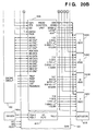
- Fig. 5 shows the arrangement of an IC (head substrate) of a printhead.
- the ICs 1 to 11 have the same arrangement.
- "*" indicates a low true signal which is true at low level.
- reference symbol VH denotes a power supply voltage applied to a heater 501; and PGND, GND (ground) of a heater power supply.
- Reference numeral 502 denotes a transistor for driving the heater 501.
- Reference symbol ODD denotes a signal for designating sending an electricity to the odd-numbered heaters 501; and EVEN, a signal for designating sending an electricity to the even-numbered heaters 501.
- Reference numeral 503 denotes a 3 to 8 decoder.
- the 128 heaters 501 are grouped into eight blocks (16 nozzles per block), and the 3 to 8 decoder 503 selects a block of heaters 501 to be driven in accordance with a block selection signal (BENB0 to BENB2).
- a block selection signal (BENB0 to BENB2).
- Reference symbol SUBH denotes a sub-heat signal; PT*, a signal for heating nozzles when no print operation is performed; MHENB*, a heat pulse signal for sending an electricity to nozzles when a print operation is actually performed; and PHEAT1* to PHEAT4*, pre-heat pulses, which are selected by a selection logic 504 in accordance with selection data set in selection data latches 505 and 506 (to be described later).
- the heaters 501 are pre-heated by the selected pulse signals.
- the signal PT* is a signal for adjusting the internal temperature of a printhead. This signal is used to apply pulses to the printhead so as to raise its temperature when the operating or environmental temperature of the printhead is low and no print operation is performed.
- the signals PHEAT1* to PHEAT4* are used as pre-heat pulses when double pulse print control is performed during a normal print operation.
- Reference numeral 508 denotes a shift register for receiving selection data for selecting the pre-heat pulses (PHEAT1* to PHEAT4*) as serial data (SI) in synchronism with a clock (SICK) and holding 128-bit data.
- the print data held in this manner is latched by a data latch 507 in response to a signal DLAT*.
- the selection data is latched by the selection data latch 505 in response to a signal LATA*, and is also latched by the selection data latch 506 in response to a latch signal LATB*.
- Reference symbol DIA denotes an input signal to a sensor 509; and DIK, an output signal from the sensor 509.
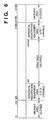
- Fig. 6 shows the heater arrangement of the printhead.
- unusable areas may be formed on the right and left portions of the printhead. For this reason, if, for example, these areas respectively include 24 nozzles near each of the right and left end portions of the printhead, a total of 1,360 nozzles are usable nozzles, which correspond to the number obtained by subtracting "48" from the total number of nozzles.
- the color printer includes the four heads corresponding to the four colors, i.e., K, C, M, and Y, and the nozzle positions (the positions of dots to be printed) of the heads of the respective colors must be accurately aligned to be superposed. If this positioning is not accurate, proper color representation cannot be attained, and a high-image quality color print operation cannot be performed. Since such a positioning operation is very minute adjustment (on the micron ( ⁇ m) order), this operation cannot be mechanically performed. For this reason, horizontal registration adjustment nozzles for positioning the printheads of the respective colors are used. The print positions of the printheads of the respective colors are adjusted depending on how many of the adjustment nozzles are used for a print operation. If the number of nozzles for horizontal registration adjustment is 16, the number of nozzles which can be used for a print operation is 1,344.
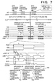
- Fig. 7 is a timing chart showing a print sequence in the printer. Note that "a" of a signal name "a-xxx" in Fig. 7 indicates color signals of K, C, M, and Y, and the respective colors correspond to these signal lines. In the following description, similar signal names will be used.
- Print data is sent, as a signal SI, to the printhead in synchronism with a SICK (serial clock) signal, and is stored in the shift register 508.
- SICK serial clock
- the signal DLAT* is made active after the data is transferred by one line, the data is temporarily stored in the data latches 507 in the ICs 1 to 11.
- heater blocks to be heated are sequentially selected in accordance with the signal ODD (odd-numbered nozzle selection signal), the signal EVEN (even-numbered nozzle selection signal), the signal BENB0 (block 0 selection signal), the signal BENB1 (block 1 selection signal), and the signal BENB2 (block 2 selection signal).
- Signals a-PH1* to a-PH4* and a-MH1* to a-MH11 are then made active to send an electricity to the heaters 501 of the respective ICs. With this operation, an ink is discharged from the corresponding nozzles to perform a print operation.
- print data for the next line is transferred while the heaters for the currently printed line are energized.
- the signal DLAT* for the next line must be made active after the lapse of one of the heat time of the heaters for the currently printed line or the data transfer time, whichever is longer. This is because, if the signal DLAT* for the next line is made active in the heat time of the heaters for the currently printed line, print data set after the signal DLAT is made active becomes print data for the next line.
- the print speed is determined mainly by the basic performance of a printhead.
- the signal DLAT* becomes active in a print operation after a normal heater energizing operation.
- reference numeral 701 denotes the energization timing of the 1st heater, the 17th heater, the 33rd heater,..., the 1,393rd heater.
- Reference numeral 702 denotes the heat timing of the 2nd heater, the 18th heater, the 34th heater,..., the 1,394th heater.
- main heat pulses of a width T3 are applied after a pre-heat period of a width T1 and a quiescent period of a width T2.
- Reference numeral 703 denotes the heat timing of the 3rd heater, the 19th heater, the 35th heater,..., the 1,395 heater. Similar to the timing 701, at the timing 703, since data is "0", only the heat pulses based on the signal a-PT* are applied.
- the printhead incorporates an EEPROM 401 for storing information about the nozzles.
- the contents stored in the EEPROM 401 include pre-pulse data, pre-pulse selection data, temperature adjustment pulse data, head rank data, and other ID data.
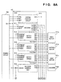
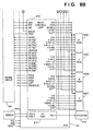
- Figs. 8A and 8B are block diagrams showing the arrangements of the gate array (GAE) 181 in the engine circuit 180.
- the GAE 181 has a function of controlling the rotations of motors 191a to 191c required for the engine circuit 180, a function of controlling an encoder 192b which operates in synchronism with the movement of printing paper, the above printhead control function, a port control function, and the like.
- Reference numeral 810 denotes a system control circuit; 811, a decoder; 812 to 814, motor drivers for rotating/driving the corresponding motors; 191a, the head motor for vertically moving the printhead 190 to perform a recovery operation therefor; 191b, the capping motor for moving a cap to cap the printhead 190; and 191c, the lead motor.
- the encoder 192b is brought into contact with printing paper as a recording medium and generates a signal upon movement of the paper.
- the signal from the encoder 192b is input to an encoder control unit 815 to generate a signal ENCCK, which is output to a head control unit 816.
- Reference numeral 192a denotes a sensor unit, which includes sensors for detecting the position of the printhead in the vertical direction, the position of the cap, and the like. Input signals from these sensors are input through an I/O port 817 and output to an actuator 818.
- Reference numeral 816 denotes a head control unit for controlling data to be output to the printheads of the respective colors, performing driving control of the printheads, and the like. The operation of the head control unit 816 will be mainly described below.
- Figs. 9A and 9B are circuit diagrams of the head control unit 816.
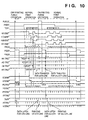
- Fig. 10 is a timing chart showing a printing operation controlled by the head control unit 816.
- the head control unit 816 includes a horizontal synchronization circuit 900, a vertical synchronization circuit 901, a transfer area circuit 902, a transfer data circuit 903, a heat area circuit 904, a heat signal circuit 905, and a sub-heater control circuit 906.
- the respective circuits will be sequentially described below.
- the horizontal synchronization circuit 900 is a circuit for generating a signal HSYNC serving as a reference signal for the printer.
- This printer uses a stepping motor as the convey motor 172.
- printing paper is conveyed by 70.5 ⁇ m (one-dot distance: 1/360 in.) per driving clock for the convey motor 172.
- the signal HSYNC signal is generated on the basis of a signal PRCK as this clock signal.
- the printer incorporates the encoder 192b capable of directly detecting the moving amount of the printing paper so that the signal HSYNC can be generated on the basis of a clock output signal (ENCCK) output from the encoder control unit 815 in accordance with a signal from the encoder 192b.
- ENCCK clock output signal
- the horizontal synchronization circuit 900 generates the above signal DLAT* on the basis of a signal HTEND* as a heat end signal for nozzle heaters.
- a signal HSTRG* is a trigger signal based on the signal HSYNC*.
- a signal PGTRG* is a trigger signal for a purge operation to be described later.
- the vertical synchronization circuit 901 generates print data request signals HK-TRG*, HC-TRG*, HM-TRG*, and HY-TRG* for the respective colors on the basis of the signal HSYNC.
- the signal HK-TRG* is output after lines (TKGAP in Fig. 10) corresponding to ((the distance from the TOF1 sensor 171a to the black head 190K) - 1) are counted with the signal HSYNC with reference to a signal TOF1 detected when printing paper is conveyed.
- a signal HK-TRG* is output after the signal HSYNCs corresponding to 141 clocks (10 x 1,000/70.5 - 1) are counted. That is, the signal HK-TRG* signal is output at the timing of transferring print data for the black head 190K.
- the signal HC-TRG* is output after lines (KCGAP in Fig. 10) corresponding to ((the distance between the black head 190K and the cyan head 190C) - 1) are counted with the signal HSYNC.
- the signal HM-TRG is output after lines (CMGAP in Fig.
- the signal HY-TRG is output after lines (MYGAP in Fig. 10) corresponding to ((the distance between the magenta head 190M and the yellow head 190Y) - 1) are counted with the signal HSYNC.
- the engine circuit 160 returns a signal HK-ENB* on the basis of the signal HK-TRG*.
- the signal HK-ENB* is used to count lines to be printed, and corresponds to the page length. While the signal HK-ENB* is active, the signal HK-TRG* is output in synchronism with the signal HSYNC* to transfer data in units of lines. The same operation is performed with respect to signals HC-ENB*, HM-ENB*, and HY-ENB*.
- print data can be transferred from the formatter 110 to the engine 150 without incorporating any print buffer in the engine 150 so that a great reduction in the cost of the engine 150 can be attained.
- the signal PRTRG* is the logical sum of a trigger signal HSTRG* output in synchronism with the signal HSYNC and the signal PGTRG*. This will be described later.
- the vertical synchronization circuit 901 also generates a signal HTTRG* for starting to send an electricity to nozzle heaters.
- the print dot positions for the respective colors must accurately coincide with each other. This is because dots of colors other than cyan, magenta, and yellow are printed while being superposed on dots of other colors. For example, a blue dot is printed by superposing cyan and magenta dots; a red dot, by superposing magenta and yellow dots; and a green dot, by superposing yellow and cyan dots.
- the print dot size is as small as 70.5 ⁇ m, such a precision cannot be mechanically attained. For this reason, a registration adjustment function is required.
- the CPU-E 161 sets the counter value for generating the above print data request signal in the GAE 181. Even if, therefore, the mechanical precision is low, the print dot positions can be accurately aligned by changing the counter value.
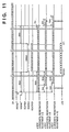
- Fig. 11 is a timing chart showing a sequence of operations of the transfer area circuit 902 and the transfer data circuit 903.
- the transfer area circuit 902 generates a signal HDATACK as a data transfer clock signal for the engine circuit 160, a signal SCAREA for generating the output timing of the SICK signal for the printhead 190, and a signal SDAREA for generating an effective area timing for each color data.
- the printhead 190 has nozzle areas which cannot be used for a print operation. For these areas, only the SICK signal must be transferred without transferring actual data with the SI signal (i.e., transferring "0" data instead). In addition, only one signal HDATACK is transferred to the engine circuit 160.
- the print positions in the horizontal direction must also be electrically adjusted.
- This adjustment method can be realized by shifting the signal SCAREA for each color and adjusting the output timing of the SICK signal for each color. More specifically, the CPU-E 161 adjusts the value of the horizontal registration adjustment register of the GAE 181 between "0" and "15” to change the number of clocks between the signal HDATACK and the SICK signal, thereby changing the positions of print nozzles in the horizontal direction. Assume that the horizontal registration adjustment of the black (K) head is set to "8", and the horizontal registration adjustment of the cyan (C) head is set to "15".
- the heat area circuit 904 generates a signal PHCK serving as a reference signal for time-divisionally sending an electricity to nozzle heaters, the time-division signals ODD, EVEN, BENB0, BENB1, and BENB2 from the signal PHCK, and signals K-FAREA, C-FAREA, M-FAREA, and Y-FAREA indicating the timings at which an electricity is time-divisionally sent to the nozzles of the respective colors. Note that the arrangement of the heat area circuit 904 will be described in detail later.
- the heat signal circuit 905 generates the signals PHEAT1* to PHEAT4* and the signals MH1* to MH11* required to perform a print operation based on double pulse control, and the signal PT* as a heat pulse for internal temperature adjustment for each color.
- a-PT* is a general term corresponding to the printheads 190K, 190C, 190M, and 190Y of the inks of the respective colors.
- the signals PHEAT1* to PHEAT4* are used as control signals for applying pre-pulses during a normal print operation.
- a circuit, in the heat signal circuit 905, which generates pre-pulses will be described in detail later.
- the printhead 190 includes sub-heaters for heating/controlling the head independently of the nozzle heaters.
- the sub-heater control circuit 906 controls the sub-heaters.
- the ink-jet printer requires an operation sequence called a recovery operation to prevent clogging of nozzles in the printhead.
- This operation is required to eliminate factors which make the ink discharge operation unstable. For example, an ink may coagulate in nozzles, or dust and the like may adhere to the orifices of nozzles. More specifically, the ink in the printhead is pressurized and circulated, or the ink is forcibly discharged from all the nozzles.
- recovery operation must be performed by only the engine 150.
- the recovery operation is basically performed during a period other than that of a print operation. If, however, the print time is long or high-density print operations are consecutively performed, a recovery operation must be performed even during the print operation. For this reason, recovery sequences are based on two operation timings, i.e., an off-printing purge operation timing and an on-printing purge operation timing, each of which requires control (see Fig. 10).
- the recovery operation of the printhead is an operation of discharging an ink from all the nozzles. No reference will be made to other operations, e.g., forcibly circulating an ink and wiping the discharge surfaces of the nozzles. An off-printing purge operation sequence will be described with reference to Fig. 10.
- the off-printing purge operation is performed.
- the transfer timing of print data differs from the nozzle heat timing of the printhead for the print data by one line. If, therefore, the above off-printing purge operation is performed during a print operation, print data for one line is lost, and printing is performed on the printing paper with all inks throughout the one line. For this reason, in the on-printing purge operation, the data transfer request signal to the formatter 110 is disabled at the timing of one line before the execution of the purge operation, and the data transfer request signal is output at the timing at which the on-printing purge operation is ended.
- This operation can be realized by controlling the timing at which the CPU-E 161 sets "1" in the PURGE register of the GAE 181 in the following manner.
- the ink discharge amount can be stabilized by using a method of applying a short pulse (pre-pulse) first, and then applying a long pulse (main pulse) rather -than by using a method of applying one longer pulse in one operation.
- the former method is called a double pulse print control method.
- Portions T1 and T3 in Fig. 7 respectively correspond to the pre-pulse and the main pulse.
- the width of the pre-heat pulse must be changed in units of nozzles. More specifically, a long pre-heat pulse is applied to a nozzle with a small discharge amount, while a short pre-heat pulse is applied to a nozzle with a large discharge amount. For this reason, a plurality of pre-pulse signals are required.
- the four types of pre-pulses are set as follows.
- the CPU-E 161 reads out pre-pulse data recorded on the EEPROM 401 in each printhead and sets the data in the GAE 181.
- the GAE 181 then generates the signals a-PH1* to a-PH4* at a proper timing.
- the pulse width setting operation in units of nozzles is determined by pre-pulse selection data.
- pre-pulse selection data There are four types of pre-pulse data, and 2-bit data may be used to select pre-pulse data through a selection circuit (not shown). More specifically, when the value of the 2-bit data is "00", the signal PHEAT1* is applied to the corresponding nozzle heater. Similarly, the signal PHEAT2* is applied when the data is "01"; the signal PHEAT3*, when the data is "10”; and the signal PHEAT4*, when the data is "11".
- This setting of the selection signals is executed in accordance with the pre-pulse setting sequence in Fig. 12.
- the symbol "a-" of each signal name in Fig. 12 is used as a general term, although different signals are used for the printheads of the respective inks.
- the CPU-E 161 reads out the LSB (bit 0) of 2-bit pre-pulse selection data from the EEPROM 401 of each printhead when the power supply of the printer is turned on. The CPU-E 161 then sets this data in the GAE 181. The GAE 181 transfers the selection data to the printhead with the signal SI in synchronism with the SICK signal. In this manner, the selection data associated with a total of 1,408 nozzles of the printhead are stored in the shift registers 508 of all the ICs of the printhead. When this transfer is completed, the signal LATA* becomes active (low active). With this operation, the selection data from the shift registers 508 are latched by the selection data latches 505.
- the CPU-E 161 reads out the MSB (bit 1) of the 2-bit pulse selection data from the EEPROM 401 in the printhead, and sets the data in the GAE 181 similar to the setting of bit 0.
- the GAE 181 outputs the selection data to the printhead with the signal SI in synchronism with the SICK signal.
- the selection data associated with a total of 1,408 nozzles of the printhead are stored in the shift registers 508 of all the ICs.
- the latch signal LATB* becomes active (low active). With this operation, the selection data from the shift registers 508 are latched by the selection data latches 506.
- the 2-bit selection data associated with a total of 1,408 nozzles of the printhead are latched in the printhead. Thereafter, optimal pre-pulses for the respective nozzles are selected in accordance with the signals PHEAT1*, PHEAT2*, PHEAT3*, and PHEAT4*. With this operation, the ink discharge amounts from the respective nozzles are made uniform to prevent density unevenness.
- the main pulse is a pulse for actually causing ink to be discharged and is controlled in units of ICs.
- Fig. 13 is a circuit diagram showing the detailed arrangement of a transfer data circuit. Since this circuit arrangement is common to print operations using four types of inks or the four printheads, Fig. 13 shows an arrangement for one printhead. For the sake of descriptive convenience, the symbol "a-" of each signal name in Fig. 13 is used as a general term, although different signals are used for the printheads of the respective inks. In practice, therefore, for example, a signal a-CSPH includes signals K-CSPH, C-CSPH, M-CSPH, and Y-CSPH according to the types of printheads.
- reference numeral 1501 denotes a shift register; 1502 to 1507, AND circuits; 1508 to 1510, OR circuits; and 1511, an inverter.
- the transfer data circuit outputs a print data signal a-DATA transferred from the engine circuit 160 as a signal a-SI to the printhead.
- the CPU-E 161 reads out the above pre-pulse selection signals from the EEPROM 401 in the printhead.
- the signal K-CSPH as a selection signal for the printhead 190K is made active.
- the GAE 181 then connects a signal SCK to a signal K-SICK, and connects a signal SDO to a signal K-SI in accordance with the signal K-CSPH.
- the CPU-E 161 transfers the LSB (bit 0) of the 2-bit pre-pulse selection signal as the signal SDO to the printhead 190K.
- the signal C-CSPH* as a selection signal for the printhead 190C is made active, and the same setting operation as that for the printhead 190K is performed.
- the signal LATA* corresponding to the port function of the GAE 181 is made active.
- the MSB (bit 1) of the 2-bit pre-pulse selection signal is transferred, as the signal SDO, to the printhead 190K by making the signal K-CSPH* active. Thereafter, the signal C-CSPH* is made active and transferred to the printhead 190C. Likewise, the signals are sequentially transferred to the printheads 190M and 190Y, and the latch signal LATB* becomes active. With this operation, data setting in the selection logic 504 of the printhead 190K is completed.
- the signals PHEAT1* to PHEAT4* in the printheads 190K, 190C, 190M, and 190Y can be selected in units of nozzle heaters.
- the signals PHEAT1* to PHEAT4* connected to the printhead 190K are respectively signals K-PH1* to K-PH4*; and the signals MH1* to MH11*, signals K-MH1* to K-MH11*.
- the signals PHEAT1* to PHEAT4* connected to the printhead 190C are respectively signals C-PH1* to C-PH4*; and the signals MH1* to MH11*, signals C-MH1* to C-MH11*.
- the signals PHEAT1* to PHEAT4* connected to the printhead 190M are respectively signals M-PH1* to M-PH4*; and the signals MH1* to MH11*, signals M-MH1* to M-MH11*.
- the signals PHEAT1* to PHEAT4* connected to the printhead 190Y are respectively signals Y-PH1* to Y-PH4*; and the signals MH1* to MH11*, signals Y-MH1* to Y-MH11*.
- Fig. 14 is a block diagram showing the arrangement of a circuit, in the heat signal circuit 905, which generates pre-pulses. Since this circuit arrangement is common to the four colors, Fig. 14 shows only an arrangement for one color.
- the symbol "a-" in Fig. 14 represents a general term of signal names, which should be represented by different symbols for the respective colors.
- reference numerals 1601 to 1604 denote T0 count circuits; 1611 to 1614, T1 count circuits; and 1621 to 1624, PH output circuits.
- the T0 count circuit 1601, the T1 count circuit 1611, and the PH output circuit 1621 generate the first type of pre-heat pulse signal (a-PH1*).
- the T0 count circuit 1602, the T1 count circuit 1612, and the PH output circuit 1622 generate the second type of pre-heat pulse signal (a-PH2*).
- the T0 count circuit 1603, the T1 count circuit 1613, and the PH output circuit 1623 generate the third type of pre-heat pulse signal (a-PH3*).
- the T0 count circuit 1604, the T1 count circuit 1614, and the PH output circuit 1624 generate the fourth type of pre-heat pulse signal (a-PH4*).
- pre-heat pulse signal As described above, since the four types of pre-heat pulse signals are generated by the circuits having the same arrangement, only the generation of the pre-heat pulse signal (a-PH1*) will be described below.
- the T0 count circuit 1601 counts a time corresponding to the value of T0 for the signal K-PH1* starting from the signal PHCK, then makes a signal SHP active.
- the T1 count circuit 1611 counts a time corresponding to the value of T1 after the signal SHP becomes active, and makes a signal HHP active.
- the PH output circuit 1621 generates the signal a-PH1* from the signals SHP and HHP.
- the signals a-PH2* to a-PH4* are also generated by the same operation as described above.
- the pre-pulse signal therefore, can be generated by connecting two counters.
- the generation of the main pulse signal requires control for each IC (as shown in Fig. 4, one printhead includes 11 ICs).
- the main pulse can also be generated by connecting two counters as in the case of a pre-pulse.
- a circuit for generating a signal (PT*) for adjusting the internal temperature is constituted by one counter for each of the color components (K, C, M, and Y) of print data.
- a signal K-PT* (see Fig. 7) as a heat pulse for this internal temperature control is made active at the leading edge of the signal PHCK, and is made inactive when a time corresponding to the value of T6 (see Fig. 7) set in the K-PT register (not shown) is counted.
- Signals C-PT*, M-PT*, and Y-PT* also change in the same manner as described above.
- Temperature control in the printhead which is based on the signals K-PT*, C-PT*, M-PT*, and Y-PT*, is performed by nozzle heaters which are not used for a print operation.
- the pre-heat pulse width is controlled for each nozzle of each printhead, and double pulse control can be performed by selecting optimal pulse widths. Therefore, variations in the ink discharge amounts from one nozzle to another nozzle can be properly corrected. With this operation, high print quality can be maintained.
- the print data output lines connected to the printheads are used to set pre-heat pulse data therein, the number of signal lines between the printer and the printheads can be reduced, and the printer can be reduced in size.
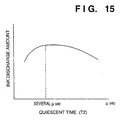
- Double pulse print control as characteristic control in this example will be described next with reference to the arrangement of the printhead IC (head substrate) in Fig. 5, the timing chart in Fig. 7 showing the print sequence, the quiescent time/ink discharge amount characteristics in Fig. 15, and the heat signal circuit (MH unit) in Fig. 16.
- the ink discharge amount can be stabilized by using a method of applying a short pulse (pre-pulse) first, and then applying a long pulse (main pulse) rather than by using a method of applying one longer pulse in one operation.
- pre-pulse short pulse
- main pulse long pulse
- control of the ink discharge amounts is called double pulse control.
- T1 denotes a pre-pulse
- a signal PT* is a signal for adjusting the internal temperature of each printhead.
- this signal is used to apply pulses to nozzle heaters which are not used for a print operation so as to raise the temperature of the printhead.
- This pulse width is set in a manner such that a CPU-E 161 reads out temperature adjustment pulse data from an EEPROM 401 in the printhead, and then sets the data in a GAE 181.
- the GAE 181 outputs the signal PT* at the timing shown in Fig. 7 on the basis of the set value ("a-PT*" in Fig.
- Signals PHEAT1* to PHEAT4* are also used as control signals for applying pre-pulses during a normal print operation.
- the ink discharge amounts from the printheads vary depending on the manufacturing processes, density unevenness occurs in an actual print operation in units of nozzles.
- the width of a pre-heat pulse therefore, must be changed in units of nozzles in order to prevent such density unevenness. More specifically, a long pre-heat pulse is applied to a nozzle with a small discharge amount, while a short pre-heat pulse is applied to a nozzle with a large discharge amount. For this reason, a plurality of signals for pre-pulses are required in accordance with the ink discharge amounts from the nozzles.
- nozzle heaters are manufactured in a semiconductor process, variations of the nozzle heaters in each printhead IC (head substrate) are small, but variations in units of ICs are large. As described above, as the variations of the nozzle heaters increase, density unevenness occurs, and the print quality deteriorates. For this reason, control must be performed to suppress density unevenness by changing the value of T3 representing the main pulse width in units of ICs.
- the CPU-E 161 reads out head rank data (a parameter which quantifies the degree of density unevenness corresponding to the IC) from the EEPROM 401 in the printhead, and sets the data in the GAE 181.
- the GAE 181 outputs a signal representing the pulse width (T3) set by a signal MHENB* at a proper timing. With this operation, density unevenness can be prevented in units of ICs.
- T2 a quiescent time between the pre-pulse (T1) and the main pulse (T3)
- the print width is long. For this reason, the internal temperature of the printhead locally rises at a portion in which printing density is high, but the internal temperature is not so high at a portion in which printing density is low . As a result, a temperature gradient is produced in one printhead. If this temperature gradient becomes steep, the ink discharge amount from each nozzle becomes unstabilized, and density unevenness occurs. For this reason, ink discharge control in consideration of this temperature off-balance is required.
- Fig. 15 shows the ink discharge amount characteristics indicating the relationship between the ink discharge amount and T2. It is known that the ink discharge amount increases to its peak while the value of T2 remains 0 to several ⁇ sec, and then gradually decreases with an increase in the value of T2. This phenomenon is associated with the mechanism of forming bubbles and ink droplets, and is well known. For this reason, a detailed description of the phenomenon will be omitted. According to the above relationship, T2 may be set to be several ⁇ sec at a low-temperature portion of the printhead, whereas T2 may be brought closer to "0" at a high-temperature portion. This control can be performed in units of LSIs in the printhead. It is known, however, that the temperature gradient is not so steep as to change in units of LSIs. That is, control in units of groups of LSIs is more advantageous because the control operation is simplified, and it contributes to reducing the circuit size of the head substrate.
- one printhead is divided into a plurality of portions, and T2 corresponding to the temperature of each divided portion is supplied to the printhead to perform ink discharge control, thereby realizing correction in consideration of the temperature gradient in the printhead.
- the head substrate arrangement of the printhead in Fig. 4 is obtained with a division number of "3".
- the CPU-E 161 detects the representative temperatures of the respective groups from signals DKA1, DIK1, DIA2, DIK2, DIA3, and DIK3 as signals from temperature sensors for the respective groups in the printhead, and sets the values of T5 corresponding to the respective representative temperatures in the GAE 181.
- the GAE 181 measures the time T5 for each of the three groups, based on the set values, and outputs a main pulse. In this manner, density unevenness caused by a temperature gradient in one printhead can be prevented.
- Figs. 16A and 16B are circuit diagrams showing the detailed arrangement of a heat signal circuit for generating a main pulse (T3).
- the heat signal circuit is a circuit for generating the signals PHEAT1* to PHEAT4* and signals MH1* to MH11* required for the above double pulse print control for each ink color. Since these signals are required for each ink color, the signals PHEAT1* to PHEAT4* connected to the printhead 190K are respectively signals K-PH1* to K-PH4*; and the signals MH1* to MH11*, signals K-MH1* to K-MH11*. Similarly, the signals PHEAT1* to PHEAT4* connected to the printhead 190C are respectively signals C-PH1* to C-PH4*; and the signals MH1* to MH11*, signals C-MH1* to C-MH11*.
- the signals PHEAT1* to PHEAT4* connected to the printhead 190M are respectively signals M-PH1* to M-PH4*; and the signals MH1* to MH11*, signals M-MH1* to M-MH11*.
- the signals PHEAT1* to PHEAT4* connected to the printhead 190Y are respectively signals Y-PH1* to Y-PH4*; and the signals MH1* to MH11*, signals Y-MH1* to Y-MH11*.
- the signal K-PH1 becomes active after a time corresponding to T0 corresponding to the signal K-PH1 on the basis of a signal PHCK, and becomes inactive after a time corresponding to T1 is counted.
- a similar operation is performed with respect to the 'signals K-PH2* to K-PH4*.
- the same operation is performed as to the signals C-PH1* to C-PH4*, M-PH1* to M-PH4*, and Y-PH1* to Y-PH4* which are respectively used for discharging inks of the respective colors.
- two counters may be connected.
- the generation of the main pulse, signal requires control for each IC (in this example, as shown in Fig. 4, one printhead includes 11 ICs).
- the main pulse can also be generated by connecting two counters as in the case of the pre-pulse.
- 88 counters are required.
- Each counter has a large circuit size. That is, the size of a circuit constituted by 88 counters is very large, and this results in deteriorating the reliability of the circuit. For this reason, in this example, the circuit arrangement is designed such that basic pulses are generated for the generation of main pulses, and necessary pulses are selected.
- the heat signal circuit for generating main pulses is constituted by a T5 count circuit 1210 for generating a pulse of T5 (see Fig. 7), selection circuits 1211 to 1214 therefor, T3 count circuits 1221 to 1232 for generating a pulse of 'T3 (see Fig. 7), selection circuits 1241 to 1252 therefor, T5 register circuits 1261 to 1264, and latch circuits 1271 to 1274.
- the total number of counters is 13 according to the above constructed circuit. That is, the circuit size is about 1/4 that of the circuit constituted by only counters.
- the signal K-MH1 will be described first.
- the T5 selection circuit 1211 selects a signal BP as an output from the T5 count circuit 1210 for counting a time corresponding to T5 set in the register (not shown) of group 1 of the printhead 190K, and determines a signal BP1*.
- the T5 selection circuit 1211 then outputs the signal BP1* to the T3 count circuit 1221.
- the T3 count circuit 1221 outputs 16 types of main pulses (MP0 to MP15) to the T3 selection circuit 1241. Selection data is set in the K-MH1 register in the T3 selection circuit 1241.
- the T3 selection circuit 1241 outputs the signal K-MP1* on the basis of the 16 input main pulses (MP0 to MP15).
- the value of T5 becomes equal to the value set in the register (not shown) of group 2 of the printhead 190K, and a signal BP2 is determined.
- the T3 count circuit 1222 performs the same operation as described above to output main pulses (MP0 to MP15).
- the T3 selection circuit 1242 selects the signal set in the K-MH5 register in the circuit, and outputs the signal K-MH5*. Similar operations are performed to output the signals K-MH6* and K-MH7*.
- the value of T5 becomes the value set in the register (not shown) of group 3 of the printhead 190K, and a signal BP3* is determined.
- Other operations are the same as those described above.
- a T5 (see Fig. 7) setting operation will be described below, in which the pulse width is changed in accordance with a change in the temperature of each printhead.
- the value of T3 is stored in the EEPROM 401 in the printhead.
- the CPU-E 161 may read out the contents of the EEPROM 401 and set them as signals D0 to D7 in the T3 selection circuits 1241 to 1252.
- the CPU-E 161 since the value of T5 must be changed in accordance with a change in temperature, the CPU-E 161 periodically reads the value of a temperature sensor in the printhead and sets values in the T5 selection circuits 1211 to 1214 of the GAE 181 in accordance with the signals D0 to D3. Since the CPU-E 161 does not manage the energization timings of nozzle heaters, the value of T5 may change during the period of sending an electricity to the nozzle heaters.
- the printer needs a circuit arrangement for preventing T5 from being changed during the period of sending an electricity to the nozzle heaters.
- the T5 register circuits 1261 to 1264 and the latch circuits 1271 to 1274 cause a main pulse signal to reflect information from the CPU-E 161, which is set in the T5 register circuits 1261 to 1264, with a delay of one line. With this operation, damage to the nozzle heaters can be prevented. Since the value of T5 does not change during the period of printing one line, no abrupt change in ink discharge amount occurs in the process of printing one line. Density unevenness of a printed image, therefore, can be prevented.
- Double pulse control can be properly performed with the above operation.
- a signal K-PT* (Fig. 7) as a heat pulse for temperature control is made active at the leading edge of the signal PHCK, and is made inactive after a time corresponding to the value of T6 (see Fig. 7) set in the K-PT register (not shown).
- This circuit is therefore constituted by one counter.
- the same circuit arrangement is used for signals C-PT*, M-PT*, and Y-PT*.
- pulse quiescent time control for each group in the printhead and main pulse width control for each IC are performed in consideration of (1) a temperature gradient and a change in temperature in the printhead and (2) variations of ICs.
- the ink discharge amounts from the respective nozzles are made uniform to allow a print operation with high print quality.
- the circuit for the above control is designed to minimize the number of counters, the circuit size can be reduced, and the overall size of the printer can also be reduced.
- Fig. 17 shows the arrangement of a printhead for one color according to this embodiment.
- the arrangement of the printhead in Fig. 17 is the same as that of the first example described with reference to Fig. 4 except that there is no signal PT* which is input to each IC in the first and second examples. A description of this therefore, will be omitted.
- Fig. 18 shows the arrangement of a head IC of the printhead according to this embodiment.
- the arrangement of the head IC in Fig. 18 is the same as that of the head IC in Fig. 5 described in the first example except that no gate for inputting the signal PT* is used. A description of this arrangement, therefore, will be omitted.
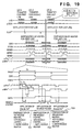
- Fig. 19 is a timing chart showing a basic print sequence according to this embodiment.
- the signals shown in Fig. 19 are the same as those in Fig. 7, described in the first example, except that the signal PT* is not included.
- reference numeral 701 denotes the energization timing of the 1st heater, the 17th heater, the 33rd heater,..., the 1,393rd heater.
- Reference numeral 702 denotes the heat timing of the 2nd heater, the 18th heater, the 34th heater,..., the 1,394th heater.
- main heat pulses of a width T3 are applied after a pre-heat period of a width T1 and a quiescent period of a width T2.
- Reference numeral 703 denotes the heat timing of the 3rd heater, the 19th heater, the 35th heater,..., the 1,395 heater. Similar to the timing 701, at the timing 703, since data is "0", only the heat pulses based on the signal a-PH* are applied.
- Figs. 20A and 20B are block diagrams showing the arrangements of an engine circuit 180 and a GAE 181 according to this embodiment. Unlike in the arrangements in Figs. 8A and 8B, described in the first example, in the arrangements of this embodiment, the signals K-PT*, C-PT*, M-PT*, and Y-PT* used in the first example need not be output from an encoder control unit 815 to printheads 190K, 190C, 190M, and 190Y. Since other arrangements are the same as those of the first example, a description thereof will be omitted.
- Figs. 21A and 21B are block diagrams showing the arrangement of a head control unit 816 of the GAE 181 according to this embodiment.
- the signals K-PT*, C-PT*, M-PT*, and Y-PT* output in the first example need not be output from a heat signal circuit 905.
- the heat signal circuit 905 in this embodiment is a circuit for generating signals PHEAT1* to PHEAT4* and signals MH1* to MH11* required to perform a print operation based on double pulse control for each color.
- the heat signal circuit 905 will be described in detail later. Since other arrangements are the same as those in the first example, a description thereof will be omitted.
- Pre-heat pulse control in double pulse print control, which is characteristic operation control in this embodiment, will be described below.
- the ink discharge amount can be stabilized by using a method of applying a short pulse (pre-pulse) first, and then applying a long pulse (main pulse) rather than by using a method of applying one longer pulse in one operation.
- Pre-pulse a short pulse
- main pulse a long pulse
- Portions T1 and T3 in Fig. 19 respectively correspond to the pre-pulse and the main pulse.
- the signals PHEAT1* to PHEAT4* connected to the printhead 190K are respectively signals K-PH1* to K-PH4*; and the signals MH1* to MH11*, signals K-MH1* to K-MH11*.
- the signals PHEAT1* to PHEAT4* connected to the printhead 190C are respectively signals C-PH1* to C-PH4*; and the signals MH1* to MH11*, signals C-MH1* to C-MH11*.
- the signals PHEAT1* to PHEAT4* connected to the printhead 190M are respectively signals M-PH1* to M-PH4*; and the signals MH1* to MH11*, signals M-MH1* to M-MH11*.
- the signals PHEAT1* to PHEAT4* connected to the printhead 190Y are respectively signals Y-PH1* to Y-PH4*; and the signals MH1* to MH11*, signals Y-MH1* to Y-MH11*.
- a full-line type printhead having a long print width like this embodiment has many ink discharge nozzles, and hence many nozzle heaters. For this reason, when a high-density print operation is performed, the nozzle heaters generate large quantities of heat, and the internal temperature of the printhead rises. As a result, it is difficult to maintain the internal temperature within the temperature range for a proper print operation.
- the printer of this embodiment includes a cooling fan to prevent such a rise in 'temperature so as to prevent an abnormal rise in the internal temperature of the printhead.
- no pre-pulse is generated in pre-pulse print control to suppress an increase in the quantity of heat generated from each nozzle heater.
- Fig. 22 is a circuit diagram showing the detailed arrangement of the heat signal circuit. Since this circuit arrangement is common to print operations using four types of inks or the four printheads, Fig. 22 shows an arrangement for one printhead. For the sake of descriptive convenience, the symbol "a-" of each signal name in Fig. 22 is used as a general term, although different signals are used for the printheads of the respective inks. In practice, therefore, for example, a signal a-FAREA includes signals K-FAREA, C-FAREA, M-FAREA, and Y-FAREA according to the types of printheads.
- reference numeral 1701 denotes a pre-pulse generation circuit; 1702, a main pulse generation circuit; and 1703, a PHLESS circuit.
- the pre-pulse generation circuit 1701 generates signals a-PH1* to a-PH4*. These signals are generated as follows.
- a CPU-E 161 reads out pre-pulse data from an EEPROM 401 in each printhead, and sets the data in the GAE 181. With this operation, a counter in the pre-pulse generation circuit 1701 as an internal circuit of the GAE 181 generates and outputs four types of pre-pulse signals (a-HPH1* to a-HPH4*) on the basis of a signal PHCK.
- the main pulse generation circuit 1702 performs a similar operation. That is, the CPU-E 161 reads out head rank data from the EEPROM 401 in the printhead, and sets the data in the GAE 181. With this operation, a counter in the main pulse generation circuit 1702 as an internal circuit of the GAE 181 generates and outputs main pulse signals (a-HMH1* to a-HMH11*) for the respective ICs (ICs 1 to 11) on the basis of the signal PHCK.
- the PHLESS circuit 1703 is a circuit for selecting, in accordance with the value set by the CPU-E 161 and stored in the a-PHOFF register (not shown) in the GAE 181, whether or not to output a pre-pulse.
- the CPU-E 161 determines, on the basis of the printing density attained by the printheads 190K, 190C, 190M, and 190Y of the printer and temperature information from temperature sensors arranged in the printheads, that the printing density is low or the temperatures of the printheads have decreased because of a low operation environmental temperature. In this case, the CPU-E 161 sets "0" in the a-PHOFF register. On the other hand, when the printing density is high or the operation environmental temperature is high, the CPU-E 161 sets "1" in the a-PHOFF register.
- Fig. 23 is a circuit diagram showing the detailed arrangement of the PHLESS circuit 1703.
- reference numeral 1710 denotes a flip-flop; 1711, an inverter; 1721 to 1725, AND circuits; and 1731 to 1741, OR circuits.
- pre-pulse signals (a-HPH1* to a-HPH4*) generated by the pre-pulse generation circuit 1701 are directly output as pre-pulse selection signals (a-PH1* to a-PH4*), and main pulse signals (a-HMH1* to a-HMH11*) generated by the main pulse generation circuit 1702 are directly output as main pulse signals (a-MH1* to a-MH11*).
- pre-pulses are applied to all the nozzle heaters in the printhead to uniformly heat the printhead. Therefore, the ink discharge amount from each nozzle is stabilized.
- pre-pulse selection signals (a-PH1* to a-PH4*)
- a-PH1* only one pre-pulse signal (a-HPH1*) is commonly applied to the OR circuits 1731 to 1741.
- signals based on the logical sums between the signal a-PH1* and the respective main pulses are respectively applied to only nozzle heaters, of the nozzle heaters of the printhead, for which print data are present.
- double pulse control is substantially executed for the nozzle heaters used for a print operation.
- a heating operation using pre-pulses is not performed for the nozzle heaters which are not used for the print operation.
- double pulse print control is performed such that no pre-pulses are applied to the printhead, and double pulses are substantially applied to only the nozzle heaters which are used for a print operation.
- the total quantity of heat generated by the nozzle heaters is suppressed low, and a rise in the temperature of each printhead can be suppressed. Even if, therefore, the operation environmental temperature is high, high print quality can be maintained.
- a combination of the control in this embodiment and the operation of the cooling fan will enhance the cooling effect.
- the cooling fan itself can be reduced in size.
- This embodiment also exemplifies a color printer using printheads for four colors.
- the present invention can be equally applied to a printer having at least one line printhead.
- the constants in this embodiment e.g., the number of nozzle heaters and the number of LSIs, are examples, and the present invention is not limited'to them.
- this embodiment exemplifies a printer constituted by a formatter and an engine as separate units.
- the present invention can be applied to an integrated printer.
- the engine in this embodiment is constituted by the two separate circuit blocks.
- the present invention is not limited to this.
- the engine may be constituted by one circuit block.
- a printer which comprises means (e.g., an electrothermal transducer, laser beam generator, and the like) for generating heat energy as energy utilized upon execution of ink discharge, and causes a change in state of an ink by the heat energy, among the ink-jet printers.
- means e.g., an electrothermal transducer, laser beam generator, and the like
- heat energy as energy utilized upon execution of ink discharge
- the system is effective because, by applying at least one driving signal, which corresponds to printing information and gives a rapid temperature rise exceeding film boiling, to each of electrothermal transducers arranged in correspondence with a sheet or liquid channels holding a liquid (ink), heat energy is generated by the electrothermal transducer to effect film boiling on the heat acting surface of the printhead, and consequently, a bubble can be formed in the liquid (ink) in one-to-one correspondence with the driving signal.
- the driving signal is applied as a pulse signal, the growth and shrinkage of the bubble can be attained instantly and adequately to achieve discharge of the liquid (ink) with the particularly high response characteristics.
- signals disclosed in U.S. Patent Nos. 4,463,359 and 4,345,262 are suitable. Note that further excellent printing can be performed by using the conditions described in U.S. Patent No. 4,313,124 of the invention which relates to the temperature rise rate of the heat acting surface.
- the arrangement using U.S. Patent Nos. 4,558,333 and 4,459,600 which disclose the arrangement having a heat acting portion arranged in a flexed region is also included in the present invention.
- the present invention can be effectively applied to an arrangement based on Japanese Patent Laid-Open No. 59-123670 which discloses the arrangement using a slot common to a plurality of electrothermal transducers as a discharge portion of the electrothermal transducers, or Japanese Patent Laid-Open No. 59-138461 which discloses the arrangement having an opening for absorbing a pressure wave of heat energy in correspondence with a discharge portion.
- a full line type printhead having a length corresponding to the width of a maximum printing medium which can be printed by the printer
- either the arrangement which satisfies the full-line length by combining a plurality of printheads as disclosed in the above specification or the arrangement as a single printhead obtained by forming printheads integrally can be used.
- an exchangeable chip type printhead as described in the above embodiment, which can be electrically connected to the apparatus main unit and can receive an ink from the apparatus main unit upon being mounted on the apparatus main unit but also a cartridge type printhead in which an ink tank is integrally arranged on the printhead itself can be applicable to the present invention.
- recovery means for the printhead, preliminary auxiliary means, and the like provided as an arrangement of the printer of the present invention since the printing operation can be further stabilized.
- examples of such means include, for the printhead, capping means, cleaning means, pressurization or suction means, and preliminary heating means using electrothermal transducers, another heating element, or a combination thereof. It is also effective for stable printing to provide a preliminary discharge mode which performs discharge independently of printing.
- the ink is a liquid.
- the present invention may employ an ink which is solid at room temperature or less and softens or liquefies at room temperature, or an ink which liquefies upon application of a use printing signal, since it is a general practice to perform temperature control of the ink itself within a range from 30°C to 70°C in the ink-jet system, so that the ink viscosity can fall within a stable discharge range.
- an ink which is solid in a non-use state and liquefies upon heating may be used.
- an ink which liquefies upon application of heat energy according to a printing signal and is discharged in a liquid state, an ink which begins to solidify when it reaches a printing medium, or the like, is applicable to the present invention.
- an ink may be situated opposite electrothermal transducers while being held in a liquid or solid state in recess portions of a porous sheet or through holes, as described in Japanese Patent Laid-Open No. 54-56847 or 60-71260.
- the above-mentioned film boiling system is most effective for the above-mentioned inks.
- the ink-jet printer of the present invention may be used in the form of a copying machine combined with a reader, and the like, or a facsimile apparatus having a transmission/reception function in addition to an image output terminal of an information processing equipment such as a computer.
- the present invention can be applied to a system constituted by a plurality of devices, or to an apparatus comprising a single device. Furthermore, it goes without saying that the invention is also applicable to a case where the object of the invention is attained by supplying a program to a system or apparatus.
Landscapes
- Particle Formation And Scattering Control In Inkjet Printers (AREA)
- Ink Jet (AREA)
Description
- This invention relates to a printer and, more particularly, to a printer for printing an image on a recording medium by using a line-type printhead.
- A printhead mounted in a conventional ink-jet printer has a considerably smaller print width than printing paper. The printhead is therefore mounted in the printer to oppose printing paper, and a carriage on which the printhead is mounted is laterally moved to perform a serial print operation.
- Density unevenness of a printed image in such a printhead is corrected by, for example, controlling the print operation of the printer by a reciprocal printing method.
- As an effective printing method for a printhead mounted in a conventional ink-jet type printer, a double pulse control printing method is known. In this method, a short pulse is applied to each nozzle heater of the printhead first, and a long pulse is then applied to each nozzle heater.
- In a line printer incorporating a full-line printhead having the same print width as that of printing paper, since the print width is large and the number of nozzles for discharging ink is large, variations in ink discharge amount per orifice and the discharge direction cannot be neglected, unlike those in a printhead mounted in a serial printer like the above conventional printer. In addition, the line printer cannot employ the reciprocal printing method, which can be employed by the serial printer, owing to its structure.
- Under the circumstances, a print control method different from that employed by the serial printer is required for the line printer to obtain a high-quality printed image free from density unevenness by making the ink discharge amounts from the ink discharge nozzles uniform.
- Furthermore, in the line printer incorporating the full-line printhead described above, since a large number of nozzle heaters are also used, due to uneven energization of the nozzle heaters depending on the printing density, and changes in operating temperature, the internal temperature of the printhead cannot be kept constant for a proper print operation, resulting in variations in the ink discharge amounts from the respective nozzles. For this reason, it is difficult to maintain good print quality.
- In a printer having a full-line printhead with the same print width as that of printing paper, since the structure of the printhead is different from that of a printhead having a small print width, printhead control is required in consideration of the following points to maintain high print quality:
- (1) Since the nozzle heaters used for the ink discharge nozzles of the full-line printhead are driven by a plurality of LSIs, variations in ink discharge amount must be suppressed in units of LSIs in consideration of variations in the quality of LSIs.
- (2) Control must be performed to suppress variations in ink discharge amount due to a temperature gradient in the printhead which results from the long print width.
- (3) Control must be performed so as not to damage the nozzle heaters when large currents are supplied to the nozzle heaters to perform control operations (1) and (2).
-
- EP-A-0496525 describes an ink jet recording apparatus wherein a recording head is driven using pulse width modulation in which the pulse width of a pre-heating pulse to be applied to a print element to be used in recording is controlled in accordance with the temperature of the printhead. EP-A-0496525 is thus concerned only with the pulses applied to print elements that are actually used for recording and does not address the problems of thermal imbalance which may arise in a line-type printhead when only some of the print elements are being used for recording.
- WO90/03554 describes a thermal printhead in which the application of a pre-pulse signal to a print element is controlled in accordance with the previous columns of data to be recorded and the current column of data.
- JP-A-4-70348 describes an ink jet image printing apparatus wherein discharge orifices to be used for recording are driven by a pre-pulse insufficient to cause ink ejection followed by a main pulse for causing ink ejection. The temperature of printhead is detected and the pulse width or pulse voltage of the pre-pulses and main pulses are controlled in accordance with the detected temperature. The main pulse may be divided at lower temperatures. Generally, no drive signal at all is applied to the discharge orifices not to be used for recording. However, where a discharge orifice not to be used for recording is arranged to be ready for recording, a pulse of small width (example 3.0 microseconds) insufficient to cause ink discharge is applied.
- Accordingly, it is an object of the present invention to provide a printer which can perform a high-image quality print operation even when a print operation is performed by using a full-line printhead having a long print width according to double pulse control.
- According to the present invention, there is provided a printing apparatus in accordance with
claim 1. - The present invention also provides a method of printing as set out in claim 13.
- In a printer embodying the present invention using the line-type printhead, when an image is to be printed on a recording medium by driving the M electrothermal transducers and M print elements corresponding to the electrothermal transducers, respectively, printing characteristic information associated with the M print elements are latched in correspondence with the M electrothermal transducers, optimal pre-pulse signals for the M print elements are selected on the basis of a plurality of input pre-pulse signals and the latched printing characteristic information, and a pre-heating operation is performed by sending an electricity to the M electrothermal transducers by using the selected pre-pulse signals. In this printer, printing characteristic information is output to the printhead, and a plurality of pre-pulse signals are also applied thereto.
- An embodiment of the present invention provides a printer having a full-line printhead capable of maintaining high print auality.
- In an embodiment a printer for generating print image data by receiving print image data from an external device, and printing an image on a recording medium on the basis of the print image data by using a line-type printhead having a plurality of print elements, and driving the plurality of print elements by using N driving circuits, comprises: division control means for dividing the N driving circuits into M groups and performing control in units of groups; temperature measurement means for measuring the internal temperature of the printhead for each of the groups; driving means for driving the printhead through the N driving circuits to perform a print operation by applying a first pulse to each of said plurality of print elements, and applying a second pulse following the first pulse; first adjustment means for adjusting a width of the second pulse for each of the N driving circuits on the basis of variations in operations of the N driving circuits; and second adjustment means for adjusting a pulse interval of the first and second pulses on the basis of M internal temperatures measured by the temperature measurement means.
- In the embodiment described above, when the printhead is driven through the N driving circuits to perform a print operation by applying the first pulse to each of the plurality of print elements and applying the second pulse thereto following the first pulse, the width of the second pulse is adjusted for each of the N driving circuits on the basis of the variations in the operations of the N driving circuits, and the pulse intervals of the first and second pulses are adjusted on the basis of the M measured internal temperatures obtained upon forming the N driving circuits into M groups.
- An embodiment of the present invention provides a printer which can always maintain good print quality without being influenced by print conditions such as the printing density and changes in temperature in the environment in which the printer is installed.
- In an embodiment of the present invention, a printer using a line-type printhead for printing an image on a recording medium by driving M electrothermal transducers and M print elements corresponding to the electrothermal transducers, respectively, according to double pulse control, comprises: monitoring means for monitoring an internal temperature of the printhead; input means for inputting print data; driving means for driving the printhead by sending an electricity to the M electrothermal transducers according to the double pulse control; and first control means for controlling the driving means to inhibit application of pre-pulse signals to the M electrothermal transducers on the basis of the internal temperature and a printing density obtained from the print data.
- In the embodiment as described above, control is performed to suppress application of pre-pulse signals to the M electrothermal transducers on the basis of the monitored internal temperature of the printhead and the printing density obtained from input print data.
- The invention is particularly advantageous since variations in printing in units of print elements in the line-type printhead can be corrected. In addition, a deterioration in print quality due to variations in the operations of the N driving circuits or change in the internal temperature of the printhead can be corrected to maintain high print quality. Furthermore, since pulse control is performed upon completion of a print operation corresponding to one line during printing, no abnormal pulse is applied to each print element of the printhead. This protects the printhead and also prevents a deterioration in print quality due to application of abnormal pulses.
- Moreover, since correction can be made to prevent variations in the print operations of the print elements due to changes in the internal temperature or printing density of the printhead, high print quality free from density unevenness can be obtained.
- Other features and advantages of the present invention will be apparent from the following description taken in conjunction with the accompanying drawings, in which like reference characters designate the same or similar parts throughout the figures thereof.
- The accompanying drawings, which are incorporated in and constitute a part of the specification, illustrate an embodiment of the invention and, together with the description, serve to explain the principles of the invention.
- Fig. 1 is a block diagram showing the circuit arrangement of a color printer having full-line ink-jet printheads;
- Fig. 2 is a sectional side view showing the schematic arrangement of the printer in Fig. 1;
- Fig. 3 is a view for explaining the printhead arrangement of the printer in Fig. 1;
- Fig. 4 is a view showing the arrangement of a printhead corresponding to one color;
- Fig. 5 is a circuit diagram showing the arrangement of a head IC of the printhead;
- Fig. 6 is a view showing the arrangement of the nozzle heaters of the printhead;
- Fig. 7 is a timing chart showing a basic printing sequence in the printer in Fig. 1;
- Figs. 8A and 8B are block diagrams showing the
arrangements of a
GAE 181 in anengine circuit 180; - Figs. 9A and 9B are block diagrams showing the
arrangements of a
head control unit 816 in theGAE 181; - Fig. 10 is a timing chart showing a print operation timing set by the head control unit;
- Fig. 11 is a timing chart showing an operation
sequence in a
transfer area circuit 902 and atransfer data circuit 903; - Fig. 12 is a timing chart showing a pre-pulse setting sequence;
- Fig. 13 is a block diagram showing the arrangement of the transfer data circuit;
- Fig. 14 is a block diagram showing the arrangement of a heat signal circuit (PH unit);
- Fig. 15 is a graph showing quiescent time/ink discharge amount characteristics;
- Figs. 16A and 16B are circuit diagrams showing the detailed arrangement of a heat signal circuit (MH unit) ;
- Fig. 17 is a view showing a full-line printhead corresponding to one color according to an embodiment of the present invention;
- Fig. 18 is a circuit diagram showing the arrangement of a head IC of the printhead according to an embodiment;
- Fig. 19 is a timing chart showing a basic print sequence according to the embodiment;
- Figs. 20A and 20B are block diagrams showing the
arrangements of a
GAE 181 in anengine circuit 180 according to the embodiment; - Figs. 21A and 21B are block diagrams showing the
arrangement of a
head control unit 816 of theGAE 181 according to the embodiment; - Fig. 22 is a block diagram showing the arrangement of a heat signal circuit (PH unit); and
- Fig. 23 is a block diagram showing the arrangement of a PHLESS circuit in Fig. 22.
-
- A typical example of a colour printer incorporating a full-line printhead (to be referred to as printhead hereinafter) will be briefly described first.
- Print data is transmitted to each printhead at the timing of a print operation for the preceding line. An engine detects this timing through a vertical registration adjustment counter, and transmits a trigger signal (a-TRG*; "*" indicates low true) for requesting print data to a formatter at the timing one line ahead of the print position. Upon detection of this signal, the formatter prepares for the transmission of the print data, and makes a vertical sync signal (a-ENB*), indicating the one-page data is being transferred, active. The engine transmits a print data reference clock signal (DATACK) to the formatter with a predetermined delay time with respect to the print data request signal. The formatter transmits the print data to the engine in synchronism with this reference clock signal. The engine directly transmits the received print data to the printhead.
- The above operation is independently performed for each color signal except for the transmission of the reference clock signal to the formatter. The print data is therefore directly transferred from the formatter to the printhead. Consequently, the print data need not be temporarily stored in the engine.
- With this operation, the transfer of the one-line print data is completed. When the one-line print data is transferred to the printhead, the engine makes a latch signal (DLAT*) active, and temporarily stores the data in the printhead. When printing paper is then conveyed and moved by one line, an ink corresponding to the print data for the first line is discharged to perform printing. Meanwhile, a print data request signal for the second line is output from the engine to the formatter, and the same print operation as that for the first line is performed.
- Subsequently, the same print operation is repeated for the third and fourth lines. While the above vertical sync signal is active, a print data request signal is transmitted to the formatter for each line in accordance with the moving amount of printing paper. In this manner, the transfer of one-page print data is completed.
- After a print data request signal becomes active, the engine uses a clock for transferring data to the printhead as a reference clock, and counts the sum total of unused nozzle heaters of the printhead and nozzles to be subjected to horizontal registration adjustment with reference clocks. After this count operation, the engine transfers reference clocks (DATACK) corresponding to the number of the print nozzle heaters to the formatter. Upon outputting the print data request signal, the engine counts reference clocks (CK) for horizontal registration adjustment for each color signal. After the count operation, the engine transfers reference clocks (a-SICK) corresponding to the total number of the nozzle heaters to the printhead. The formatter transfers print data (a-DATA) for each color in synchronism with the reference clocks (DATACK) transferred from the engine. The print data transferred to the engine in this manner is sent to the printhead through the engine.
- With this operation, after the reference clocks for horizontal registration adjustment are input to the printhead for each color, the print data synchronized with the reference clocks is input to the printhead together with the reference clocks. Thereafter, clocks for horizontal registration adjustment are input to the printhead again, thereby allowing horizontal registration adjustment.
- In a line printer, while a given line is printed, data for the next line is sent to a printhead. In cleaning the printhead, therefore, the engine stops outputting the print data request signal one line before a head cleaning operation during printing. After the printhead cleaning operation is completed, the engine outputs the print data request signal. The data set when the purge operation is performed during printing is rewritten, and the print data set before the purge operation is stored in the printhead after the purge operation. With this operation, even if the printing paper moves and a data transfer request signal is output, printing can be properly performed.
- Fig. 1 is a block diagram showing the circuit arrangement of a color printer (to be referred to as a printer hereinafter) having full-line printheads.
- As shown in Fig. 1, the circuit of this printer is constituted by a
formatter 110 for controlling communication with a host computer (to be referred to as a host hereinafter) and bitmapping data into a bitmap RAM, and anengine 150 for performing various control operations for the printheads and controlling a convey motor and various sensors. - This arrangement is designed for the following purpose. The
formatter 110 requires a circuit arrangement corresponding to various applications (e.g., a facsimile apparatus and a copying machine as well as a printer) in consideration of different interfaces with the host and different image processing methods. In contrast to this, theengine 150 is designed to reduce differences dependent on applications, and is standardized to cope with any applications, thereby attaining a reduction in cost. - The following functions are assigned to the
formatter 110 and theengine 150. - (1) Functions of Formatter
- interfacing with the host
- analyzing a command sent from the host
- bitmapping print data into the bitmap RAM on the basis of the command
- control of an operation panel
- control of a control box (to be described later)
- interfacing with the
engine 150 - option control: control (option IN) of a printing paper supply unit, and control (operation OUT) of printing paper discharge unit
- (2) Functions of Engine
- interfacing with the
formatter 110 - control of an ink supply subsystem
- control of a paper convey subsystem
- data transfer control for each printhead
- heater on/off control of each printhead
- temperature management
- timepiece function
- backup memory function
- printing paper width detection function
- interfacing with the
-
- In order to realize these functions, the following circuit arrangement is required.
- Referring to Fig. 1, the
formatter 110 is constituted by a CPU-F 111 for executing control programs, aROM 112 for storing the control programs, asystem RAM 113 for executing programs, an IFCNT 114 for communication with the host, abit map RAM 115 for storing the bitmap data of print contents transmitted from the host, acircuit GAF 116 dedicated for controlling thebit map RAM 115 and performing communication with theengine 150, an emulation ROM (E-ROM) 117 for analyzing print data from the host, a character generator (CG-ROM) 118 for converting character code data into bitmap data, amemory card 119 used as an external memory, an I/O port 120 serving as an interface with the above option control functions, and anoperation panel 121 serving as a user interface and including keys for various operations, an LCD for displaying a message from the printer, and the like. -
Reference numeral 122 denotes a control box which serves as a user interface to perform various instruction input operations when this printer performs an image print operation by using image data stored in thememory card 119 in a stand-alone manner without being connected to the host; and 123 and 124, input/output interfaces (an option IN and an option OUT) with various apparatuses to be connected, as options, to the printer. The printing paper supply unit (to be described later) is connected to the option IN 123, and the printing paper discharge unit (to be described later) is connected to theoption OUT 124. - The
engine 150 will be described next. - As shown in Fig. 1, the
engine 150 is constituted by anengine circuit 160 mainly designed for a printing paper conveying operation, and anengine circuit 180 mainly designed for printhead driving control. - The
engine 150 is constituted by a CPU-E 161 including a ROM for storing control programs, a RAM used as a work area to execute the programs, a port for receiving a signal from a sensor (to be described later), and an A/D converter for converting an analog input from the port into digital data, and adapted to execute the control programs to perform various control operations, aRAM 162 used when the CPU-E 161 executes a program, anEEPROM 163 for storing unevenness correction data for each printhead, a clock counter (RTC) 164, and aGAE 165 dedicated for generating test print data and performing communication with theformatter 110.Reference numeral 171 denotes a sensor for detecting the position of printing paper; and 172, a convey motor for conveying the printing paper. - The
engine circuit 180 includes acircuit GAE 181 dedicated for driving/controlling aprinthead 190, controlling amotor 191 for moving theprinthead 190 and a cap (not shown) to cap the ink discharge nozzles of theprinthead 190 when no print operation is performed, and controlling asensor 192 for detecting the positions of the cap and the printhead. - Fig. 2 is a sectional side view showing the schematic arrangement of a
printer 100 described above with reference to Fig. 1. Fig. 2 shows theprinter 100 incorporating thecontrol box 122, a printingpaper supply unit 130 using roll paper as printing paper, and a printingpaper discharge unit 131 having a cutter for cutting the roll paper after a print operation. Theengine 150 is divided into these twoparts -
Reference numeral 190Y denotes a full-line printhead (Y head) for performing printing by using yellow (Y) ink; 190M, a full-line printhead (M head) for performing printing by using magenta (M) ink; 190C, a full-line printhead (C head) for performing printing by using cyan (C) ink; and 190K, a full-line printhead (K head) for performing printing by using black (K) ink. These printheads are arranged along the convey direction of printing paper. -
Reference numeral 171a denotes a sensor for detecting the leading portion of the printing paper from black lines printed on the roll paper at predetermined equal intervals and generating a signal (TOF1); 171b, a sensor for detecting the leading portion of the printing paper from a black line printed on the roll paper after a print operation, and generating another signal (TOF2); and 173, a convey belt which is rotated/driven upon rotation of the conveymotor 172. When the conveybelt 173 is moved, the printing paper (recording medium) placed on the conveybelt 173 is conveyed. - Fig. 3 shows the printhead arrangement of the print unit of the printer
- The
printhead 190 is constituted by four line heads, i.e., the K head for discharging black ink, the C head for discharging cyan ink, the M head for discharging a magenta ink, and the Y head for discharging yellow ink. - As shown in Figs. 2 and 3, the printing paper is conveyed from the K head (190K) side and sequentially passes below the C head (190C), the M head (190M), and the Y head (190Y). When the printing paper passes below these heads, print data corresponding to the head portions of the respective colors are transferred to the heads, and the nozzle heaters in the heads are energized in accordance with the print data. With this operation, the inks are discharged from the corresponding nozzles to execute a print operation.
- Fig. 4 shows the arrangement of a printhead of the printer. As shown in Fig. 3 as well, each printhead includes
ICs 1 to 11 each having 128 nozzles. - Fig. 5 shows the arrangement of an IC (head substrate) of a printhead. The
ICs 1 to 11 have the same arrangement. In the following description, "*" indicates a low true signal which is true at low level. - Referring to Fig. 5, reference symbol VH denotes a power supply voltage applied to a
heater 501; and PGND, GND (ground) of a heater power supply.Reference numeral 502 denotes a transistor for driving theheater 501. Reference symbol ODD denotes a signal for designating sending an electricity to the odd-numberedheaters 501; and EVEN, a signal for designating sending an electricity to the even-numberedheaters 501.Reference numeral 503 denotes a 3 to 8 decoder. In this embodiment, the 128heaters 501 are grouped into eight blocks (16 nozzles per block), and the 3 to 8decoder 503 selects a block ofheaters 501 to be driven in accordance with a block selection signal (BENB0 to BENB2). Reference symbol SUBH denotes a sub-heat signal; PT*, a signal for heating nozzles when no print operation is performed; MHENB*, a heat pulse signal for sending an electricity to nozzles when a print operation is actually performed; and PHEAT1* to PHEAT4*, pre-heat pulses, which are selected by aselection logic 504 in accordance with selection data set in selection data latches 505 and 506 (to be described later). Theheaters 501 are pre-heated by the selected pulse signals. - In this case, the signal PT* is a signal for adjusting the internal temperature of a printhead. This signal is used to apply pulses to the printhead so as to raise its temperature when the operating or environmental temperature of the printhead is low and no print operation is performed. The signals PHEAT1* to PHEAT4* are used as pre-heat pulses when double pulse print control is performed during a normal print operation.
-
Reference numeral 508 denotes a shift register for receiving selection data for selecting the pre-heat pulses (PHEAT1* to PHEAT4*) as serial data (SI) in synchronism with a clock (SICK) and holding 128-bit data. The print data held in this manner is latched by adata latch 507 in response to a signal DLAT*. The selection data is latched by the selection data latch 505 in response to a signal LATA*, and is also latched by the selection data latch 506 in response to a latch signal LATB*. Reference symbol DIA denotes an input signal to asensor 509; and DIK, an output signal from thesensor 509. - Fig. 6 shows the heater arrangement of the printhead.
- The total number of nozzles of the printhead is 128 x 11 = 1,408. In the manufacturing process for a printhead, unusable areas may be formed on the right and left portions of the printhead. For this reason, if, for example, these areas respectively include 24 nozzles near each of the right and left end portions of the printhead, a total of 1,360 nozzles are usable nozzles, which correspond to the number obtained by subtracting "48" from the total number of nozzles.
- As described above, the color printer includes the four heads corresponding to the four colors, i.e., K, C, M, and Y, and the nozzle positions (the positions of dots to be printed) of the heads of the respective colors must be accurately aligned to be superposed. If this positioning is not accurate, proper color representation cannot be attained, and a high-image quality color print operation cannot be performed. Since such a positioning operation is very minute adjustment (on the micron (µm) order), this operation cannot be mechanically performed. For this reason, horizontal registration adjustment nozzles for positioning the printheads of the respective colors are used. The print positions of the printheads of the respective colors are adjusted depending on how many of the adjustment nozzles are used for a print operation. If the number of nozzles for horizontal registration adjustment is 16, the number of nozzles which can be used for a print operation is 1,344.
- Fig. 7 is a timing chart showing a print sequence in the printer. Note that "a" of a signal name "a-xxx" in Fig. 7 indicates color signals of K, C, M, and Y, and the respective colors correspond to these signal lines. In the following description, similar signal names will be used.
- Print data is sent, as a signal SI, to the printhead in synchronism with a SICK (serial clock) signal, and is stored in the
shift register 508. When the signal DLAT* is made active after the data is transferred by one line, the data is temporarily stored in the data latches 507 in theICs 1 to 11. Thereafter, heater blocks to be heated are sequentially selected in accordance with the signal ODD (odd-numbered nozzle selection signal), the signal EVEN (even-numbered nozzle selection signal), the signal BENB0 (block 0 selection signal), the signal BENB1 (block 1 selection signal), and the signal BENB2 (block 2 selection signal). Signals a-PH1* to a-PH4* and a-MH1* to a-MH11 are then made active to send an electricity to theheaters 501 of the respective ICs. With this operation, an ink is discharged from the corresponding nozzles to perform a print operation. - Note that print data for the next line is transferred while the heaters for the currently printed line are energized. The signal DLAT* for the next line must be made active after the lapse of one of the heat time of the heaters for the currently printed line or the data transfer time, whichever is longer. This is because, if the signal DLAT* for the next line is made active in the heat time of the heaters for the currently printed line, print data set after the signal DLAT is made active becomes print data for the next line.
- In general, the print speed is determined mainly by the basic performance of a printhead. In this case, since the heat time of the heaters is longer than the data transfer time, the signal DLAT* becomes active in a print operation after a normal heater energizing operation.
- Referring to Fig. 7,
reference numeral 701 denotes the energization timing of the 1st heater, the 17th heater, the 33rd heater,..., the 1,393rd heater. At thetiming 701, since data (DATA) is "0", only the heat pulses based on a signal a-PT* are applied.Reference numeral 702 denotes the heat timing of the 2nd heater, the 18th heater, the 34th heater,..., the 1,394th heater. At thetiming 702, since data is "1", main heat pulses of a width T3 are applied after a pre-heat period of a width T1 and a quiescent period of a width T2.Reference numeral 703 denotes the heat timing of the 3rd heater, the 19th heater, the 35th heater,..., the 1,395 heater. Similar to thetiming 701, at thetiming 703, since data is "0", only the heat pulses based on the signal a-PT* are applied. - As shown in Fig. 4, the printhead incorporates an
EEPROM 401 for storing information about the nozzles. For example, the contents stored in theEEPROM 401 include pre-pulse data, pre-pulse selection data, temperature adjustment pulse data, head rank data, and other ID data. - Figs. 8A and 8B are block diagrams showing the arrangements of the gate array (GAE) 181 in the
engine circuit 180. - The
GAE 181 has a function of controlling the rotations ofmotors 191a to 191c required for theengine circuit 180, a function of controlling anencoder 192b which operates in synchronism with the movement of printing paper, the above printhead control function, a port control function, and the like.Reference numeral 810 denotes a system control circuit; 811, a decoder; 812 to 814, motor drivers for rotating/driving the corresponding motors; 191a, the head motor for vertically moving theprinthead 190 to perform a recovery operation therefor; 191b, the capping motor for moving a cap to cap theprinthead 190; and 191c, the lead motor. Theencoder 192b is brought into contact with printing paper as a recording medium and generates a signal upon movement of the paper. The signal from theencoder 192b is input to anencoder control unit 815 to generate a signal ENCCK, which is output to ahead control unit 816.Reference numeral 192a denotes a sensor unit, which includes sensors for detecting the position of the printhead in the vertical direction, the position of the cap, and the like. Input signals from these sensors are input through an I/O port 817 and output to anactuator 818.Reference numeral 816 denotes a head control unit for controlling data to be output to the printheads of the respective colors, performing driving control of the printheads, and the like. The operation of thehead control unit 816 will be mainly described below. - Figs. 9A and 9B are circuit diagrams of the
head control unit 816. Fig. 10 is a timing chart showing a printing operation controlled by thehead control unit 816. - The
head control unit 816 includes ahorizontal synchronization circuit 900, avertical synchronization circuit 901, atransfer area circuit 902, atransfer data circuit 903, aheat area circuit 904, aheat signal circuit 905, and asub-heater control circuit 906. The respective circuits will be sequentially described below. - The
horizontal synchronization circuit 900 is a circuit for generating a signal HSYNC serving as a reference signal for the printer. This printer uses a stepping motor as the conveymotor 172. For example, printing paper is conveyed by 70.5 µm (one-dot distance: 1/360 in.) per driving clock for the conveymotor 172. The signal HSYNC signal is generated on the basis of a signal PRCK as this clock signal. - In some case, the friction coefficient between printing paper and the convey
belt 173 is small, and the rotation distance of the conveymotor 172 does not coincide with the moving distance of the printing paper. For this reason, the printer incorporates theencoder 192b capable of directly detecting the moving amount of the printing paper so that the signal HSYNC can be generated on the basis of a clock output signal (ENCCK) output from theencoder control unit 815 in accordance with a signal from theencoder 192b. - The
horizontal synchronization circuit 900 generates the above signal DLAT* on the basis of a signal HTEND* as a heat end signal for nozzle heaters. A signal HSTRG* is a trigger signal based on the signal HSYNC*. A signal PGTRG* is a trigger signal for a purge operation to be described later. - The
vertical synchronization circuit 901 generates print data request signals HK-TRG*, HC-TRG*, HM-TRG*, and HY-TRG* for the respective colors on the basis of the signal HSYNC. The signal HK-TRG* is output after lines (TKGAP in Fig. 10) corresponding to ((the distance from theTOF1 sensor 171a to theblack head 190K) - 1) are counted with the signal HSYNC with reference to a signal TOF1 detected when printing paper is conveyed. If, for example, the distance from theTOF1 sensor 171a to theblack head 190K is 10 mm, a signal HK-TRG* is output after the signal HSYNCs corresponding to 141 clocks (10 x 1,000/70.5 - 1) are counted. That is, the signal HK-TRG* signal is output at the timing of transferring print data for theblack head 190K. The signal HC-TRG* is output after lines (KCGAP in Fig. 10) corresponding to ((the distance between theblack head 190K and thecyan head 190C) - 1) are counted with the signal HSYNC. Similarly, the signal HM-TRG is output after lines (CMGAP in Fig. 10) corresponding to ((the distance between thecyan head 190C and themagenta head 190M) -1) are counted with the signal HSYNC. The signal HY-TRG is output after lines (MYGAP in Fig. 10) corresponding to ((the distance between themagenta head 190M and theyellow head 190Y) - 1) are counted with the signal HSYNC. With these operations, data can be transferred to the head of each color at the timing one line ahead of the position of the printhead. - The
engine circuit 160 returns a signal HK-ENB* on the basis of the signal HK-TRG*. The signal HK-ENB* is used to count lines to be printed, and corresponds to the page length. While the signal HK-ENB* is active, the signal HK-TRG* is output in synchronism with the signal HSYNC* to transfer data in units of lines. The same operation is performed with respect to signals HC-ENB*, HM-ENB*, and HY-ENB*. - With this data transfer method, print data can be transferred from the
formatter 110 to theengine 150 without incorporating any print buffer in theengine 150 so that a great reduction in the cost of theengine 150 can be attained. - The signal PRTRG* is the logical sum of a trigger signal HSTRG* output in synchronism with the signal HSYNC and the signal PGTRG*. This will be described later.
- The
vertical synchronization circuit 901 also generates a signal HTTRG* for starting to send an electricity to nozzle heaters. - As described above, in the color printer, the print dot positions for the respective colors must accurately coincide with each other. This is because dots of colors other than cyan, magenta, and yellow are printed while being superposed on dots of other colors. For example, a blue dot is printed by superposing cyan and magenta dots; a red dot, by superposing magenta and yellow dots; and a green dot, by superposing yellow and cyan dots. However, since the print dot size is as small as 70.5 µm, such a precision cannot be mechanically attained. For this reason, a registration adjustment function is required. In this printer, the CPU-
E 161 sets the counter value for generating the above print data request signal in theGAE 181. Even if, therefore, the mechanical precision is low, the print dot positions can be accurately aligned by changing the counter value. - Fig. 11 is a timing chart showing a sequence of operations of the
transfer area circuit 902 and thetransfer data circuit 903. - The
transfer area circuit 902 generates a signal HDATACK as a data transfer clock signal for theengine circuit 160, a signal SCAREA for generating the output timing of the SICK signal for theprinthead 190, and a signal SDAREA for generating an effective area timing for each color data. - As described above, the
printhead 190 has nozzle areas which cannot be used for a print operation. For these areas, only the SICK signal must be transferred without transferring actual data with the SI signal (i.e., transferring "0" data instead). In addition, only one signal HDATACK is transferred to theengine circuit 160. For this reason, in order to perform horizontal registration adjustment in theGAE 181 for each color, the SICK signal corresponding to the total number of nozzles may be output after the SICK signal is delayed by a time corresponding to a registration adjustment area with respect to the signal SCAREA, and the signal HDATACK corresponding to the number of print dots may be output after the signal HDATACK is delayed by a time corresponding to (an area which cannot be used for a print operation (24 nozzles)) + (a horizontal registration adjustment area (16 nozzles) = ) 40 clocks with respect to the signal SCAREA. - As described above, since an increase in mechanical position precision is limited, the print positions in the horizontal direction must also be electrically adjusted. This adjustment method can be realized by shifting the signal SCAREA for each color and adjusting the output timing of the SICK signal for each color. More specifically, the CPU-
E 161 adjusts the value of the horizontal registration adjustment register of theGAE 181 between "0" and "15" to change the number of clocks between the signal HDATACK and the SICK signal, thereby changing the positions of print nozzles in the horizontal direction. Assume that the horizontal registration adjustment of the black (K) head is set to "8", and the horizontal registration adjustment of the cyan (C) head is set to "15". In this case, eight nozzles of the print nozzles of theblack head 190K on the right side are set as unused nozzles for horizontal registration adjustment, and 15 nozzles of the print nozzles of thecyan head 190C on the right side are set as unused nozzles for horizontal registration adjustment. In this state, a print operation is performed. - The
heat area circuit 904 generates a signal PHCK serving as a reference signal for time-divisionally sending an electricity to nozzle heaters, the time-division signals ODD, EVEN, BENB0, BENB1, and BENB2 from the signal PHCK, and signals K-FAREA, C-FAREA, M-FAREA, and Y-FAREA indicating the timings at which an electricity is time-divisionally sent to the nozzles of the respective colors. Note that the arrangement of theheat area circuit 904 will be described in detail later. - The
heat signal circuit 905 generates the signals PHEAT1* to PHEAT4* and the signals MH1* to MH11* required to perform a print operation based on double pulse control, and the signal PT* as a heat pulse for internal temperature adjustment for each color. Referring to Fig. 7, "a-PT*" is a general term corresponding to theprintheads - A circuit, in the
heat signal circuit 905, which generates pre-pulses will be described in detail later. - The
printhead 190 includes sub-heaters for heating/controlling the head independently of the nozzle heaters. Thesub-heater control circuit 906 controls the sub-heaters. - The ink-jet printer requires an operation sequence called a recovery operation to prevent clogging of nozzles in the printhead. This operation is required to eliminate factors which make the ink discharge operation unstable. For example, an ink may coagulate in nozzles, or dust and the like may adhere to the orifices of nozzles. More specifically, the ink in the printhead is pressurized and circulated, or the ink is forcibly discharged from all the nozzles.
- Such an operation is irrelevant to the normal operation of the printer and must be performed independently of the
formatter 110. Therefore, the recovery operation must be performed by only theengine 150. The recovery operation is basically performed during a period other than that of a print operation. If, however, the print time is long or high-density print operations are consecutively performed, a recovery operation must be performed even during the print operation. For this reason, recovery sequences are based on two operation timings, i.e., an off-printing purge operation timing and an on-printing purge operation timing, each of which requires control (see Fig. 10). - The recovery operation of the printhead is an operation of discharging an ink from all the nozzles. No reference will be made to other operations, e.g., forcibly circulating an ink and wiping the discharge surfaces of the nozzles. An off-printing purge operation sequence will be described with reference to Fig. 10.
- (1) The CPU-
E 161 sets "1" first in the PURGE register of theGAE 181, and then sets "0" therein. - (2) The
GAE 181 sets a signal PGOP indicating the execution of a purge operation to "1", and causes thehorizontal synchronization circuit 900 to output the signal PGTRG*. - (3) The
vertical synchronization circuit 901 outputs the signal HTTRG* on the basis of the signal PGTRG*. At this time, the signal PRTRG* is not output because no print data is requested. - (4) The
transfer data circuit 903 fixes the signal SI as the print data of each color to high level and transfers the SICK signal. The detailed arrangement and operation of thetransfer data circuit 903 will be described later. - (5) The
heat area circuit 904 and theheat signal circuit 905 generate normal double pulses from the signal HTTRG* to discharge an ink from printheads. When this ink discharging operation is completed, the signal HTEND* becomes active. - (6) The
horizontal synchronization circuit 900 makes the signal DLAT* active in accordance with the signal HTEND*. With this operation, all the data in the printhead are set to the ON ("1") state, and afterward ink is discharged from all of orifices in the printhead (hereinafter this ink discharge operation is referred to as "a full-dot discharging operation"). - (7) The
vertical synchronization circuit 901 counts the signal DLAT*, and the CPU-E 161 performs a full-dot discharging operation the number of times set in the NPG register of theGAE 181. - (8) When the operation is completed, the
GAE 181 sets the signal PGOP to "0", and the CPU-E 161 reads this signal and detects the end of the purge operation. -
- With the above operations, the off-printing purge operation is performed.
- As described above, the transfer timing of print data differs from the nozzle heat timing of the printhead for the print data by one line. If, therefore, the above off-printing purge operation is performed during a print operation, print data for one line is lost, and printing is performed on the printing paper with all inks throughout the one line. For this reason, in the on-printing purge operation, the data transfer request signal to the
formatter 110 is disabled at the timing of one line before the execution of the purge operation, and the data transfer request signal is output at the timing at which the on-printing purge operation is ended. This operation can be realized by controlling the timing at which the CPU-E 161 sets "1" in the PURGE register of theGAE 181 in the following manner. - (1) The CPU-
E 161 detects the timing of the execution of an on-printing purge operation through some means. - (2) The CPU-
E 161 sets "1" in the PURGE register of theGAE 181. - (3) The
vertical synchronization circuit 901 of theGAE 181 masks the signal PRTRG* as the print data request signal to inhibit its output. - (4) The CPU-
E 161 sends a clock to the conveymotor 172 to convey the printing paper by one dot. - (5) Although the
GAE 181 generates the signal HSYNC, the signal PRTRG* is not output. For this reason, data transfer from theformatter 110 is not performed. Since the signal HTTRG* is output, data for the m-th line is printed. - (6) The CPU-
E 161 sets "0" in the PURGE register of theGAE 181. - (7) The
vertical synchronization circuit 901 of theGAE 181 cancels the masked state of the signal PRTRG* to output it afterward. - (8) The
GAE 181 performs the same operation as the off-printing purge operation. - (9) When the off-printing purge operation is
completed, the
vertical synchronization circuit 901 of theGAE 181 outputs a signal PPTRG*. - (10) The
transfer area circuit 902 and thetransfer data circuit 903 of theGAE 181 transfer data for the (m + 1)th line. - (11) After the signal SCAREA becomes inactive by
the signal PPTRG*, the
horizontal synchronization circuit 900 of theGAE 181 outputs the signal DLAT*. - (12) The normal print operation is resumed.
-
- With the above operations, not only the on-printing purge operation is properly performed, but also a proper print operation is performed.
- As known well, in applying a voltage to each nozzle heater, the ink discharge amount can be stabilized by using a method of applying a short pulse (pre-pulse) first, and then applying a long pulse (main pulse) rather -than by using a method of applying one longer pulse in one operation. The former method is called a double pulse print control method. Portions T1 and T3 in Fig. 7 respectively correspond to the pre-pulse and the main pulse.
- Four types of pre-pulse signals are used for the four
printheads - Since the ink discharge amount per nozzle of the printheads varies depending on the manufacturing processes, density unevenness occurs on a printed image in units of nozzles. In order to prevent such density unevenness, the width of the pre-heat pulse, therefore, must be changed in units of nozzles. More specifically, a long pre-heat pulse is applied to a nozzle with a small discharge amount, while a short pre-heat pulse is applied to a nozzle with a large discharge amount. For this reason, a plurality of pre-pulse signals are required.
- The four types of pre-pulses are set as follows. The CPU-
E 161 reads out pre-pulse data recorded on theEEPROM 401 in each printhead and sets the data in theGAE 181. TheGAE 181 then generates the signals a-PH1* to a-PH4* at a proper timing. - The pulse width setting operation in units of nozzles is determined by pre-pulse selection data. There are four types of pre-pulse data, and 2-bit data may be used to select pre-pulse data through a selection circuit (not shown). More specifically, when the value of the 2-bit data is "00", the signal PHEAT1* is applied to the corresponding nozzle heater. Similarly, the signal PHEAT2* is applied when the data is "01"; the signal PHEAT3*, when the data is "10"; and the signal PHEAT4*, when the data is "11".
- This setting of the selection signals is executed in accordance with the pre-pulse setting sequence in Fig. 12. For the sake of descriptive convenience, the symbol "a-" of each signal name in Fig. 12 is used as a general term, although different signals are used for the printheads of the respective inks.
- The CPU-
E 161 reads out the LSB (bit 0) of 2-bit pre-pulse selection data from theEEPROM 401 of each printhead when the power supply of the printer is turned on. The CPU-E 161 then sets this data in theGAE 181. TheGAE 181 transfers the selection data to the printhead with the signal SI in synchronism with the SICK signal. In this manner, the selection data associated with a total of 1,408 nozzles of the printhead are stored in the shift registers 508 of all the ICs of the printhead. When this transfer is completed, the signal LATA* becomes active (low active). With this operation, the selection data from the shift registers 508 are latched by the selection data latches 505. - Subsequently, the CPU-
E 161 reads out the MSB (bit 1) of the 2-bit pulse selection data from theEEPROM 401 in the printhead, and sets the data in theGAE 181 similar to the setting ofbit 0. TheGAE 181 outputs the selection data to the printhead with the signal SI in synchronism with the SICK signal. In this manner, the selection data associated with a total of 1,408 nozzles of the printhead are stored in the shift registers 508 of all the ICs. When this transfer operation is completed, the latch signal LATB* becomes active (low active). With this operation, the selection data from the shift registers 508 are latched by the selection data latches 506. - With the above operation, the 2-bit selection data associated with a total of 1,408 nozzles of the printhead are latched in the printhead. Thereafter, optimal pre-pulses for the respective nozzles are selected in accordance with the signals PHEAT1*, PHEAT2*, PHEAT3*, and PHEAT4*. With this operation, the ink discharge amounts from the respective nozzles are made uniform to prevent density unevenness.
- Note that the main pulse is a pulse for actually causing ink to be discharged and is controlled in units of ICs.
- The above pre-pulse data setting operation will be described next with reference to an actual circuit.
- Fig. 13 is a circuit diagram showing the detailed arrangement of a transfer data circuit. Since this circuit arrangement is common to print operations using four types of inks or the four printheads, Fig. 13 shows an arrangement for one printhead. For the sake of descriptive convenience, the symbol "a-" of each signal name in Fig. 13 is used as a general term, although different signals are used for the printheads of the respective inks. In practice, therefore, for example, a signal a-CSPH includes signals K-CSPH, C-CSPH, M-CSPH, and Y-CSPH according to the types of printheads.
- Referring to Fig. 13,
reference numeral 1501 denotes a shift register; 1502 to 1507, AND circuits; 1508 to 1510, OR circuits; and 1511, an inverter. - In a normal print operation, the transfer data circuit outputs a print data signal a-DATA transferred from the
engine circuit 160 as a signal a-SI to the printhead. When the power supply of the printer is turned on, the CPU-E 161 reads out the above pre-pulse selection signals from theEEPROM 401 in the printhead. - First of all, the signal K-CSPH as a selection signal for the
printhead 190K is made active. TheGAE 181 then connects a signal SCK to a signal K-SICK, and connects a signal SDO to a signal K-SI in accordance with the signal K-CSPH. The CPU-E 161 transfers the LSB (bit 0) of the 2-bit pre-pulse selection signal as the signal SDO to theprinthead 190K. When this transfer operation is completed, the signal C-CSPH* as a selection signal for theprinthead 190C is made active, and the same setting operation as that for theprinthead 190K is performed. The same applies to theprintheads GAE 181 is made active. - Next, the MSB (bit 1) of the 2-bit pre-pulse selection signal is transferred, as the signal SDO, to the
printhead 190K by making the signal K-CSPH* active. Thereafter, the signal C-CSPH* is made active and transferred to theprinthead 190C. Likewise, the signals are sequentially transferred to theprintheads selection logic 504 of theprinthead 190K is completed. - With the above operation, the signals PHEAT1* to PHEAT4* in the
printheads - These pre-pulses and main pulses are required for each ink color (or each printhead). For this reason, the signals PHEAT1* to PHEAT4* connected to the
printhead 190K are respectively signals K-PH1* to K-PH4*; and the signals MH1* to MH11*, signals K-MH1* to K-MH11*. Similarly, the signals PHEAT1* to PHEAT4* connected to theprinthead 190C are respectively signals C-PH1* to C-PH4*; and the signals MH1* to MH11*, signals C-MH1* to C-MH11*. The signals PHEAT1* to PHEAT4* connected to theprinthead 190M are respectively signals M-PH1* to M-PH4*; and the signals MH1* to MH11*, signals M-MH1* to M-MH11*. The signals PHEAT1* to PHEAT4* connected to theprinthead 190Y are respectively signals Y-PH1* to Y-PH4*; and the signals MH1* to MH11*, signals Y-MH1* to Y-MH11*. - Fig. 14 is a block diagram showing the arrangement of a circuit, in the
heat signal circuit 905, which generates pre-pulses. Since this circuit arrangement is common to the four colors, Fig. 14 shows only an arrangement for one color. The symbol "a-" in Fig. 14 represents a general term of signal names, which should be represented by different symbols for the respective colors. Referring to Fig. 14,reference numerals 1601 to 1604 denote T0 count circuits; 1611 to 1614, T1 count circuits; and 1621 to 1624, PH output circuits. - In this arrangement, the
T0 count circuit 1601, theT1 count circuit 1611, and thePH output circuit 1621 generate the first type of pre-heat pulse signal (a-PH1*). TheT0 count circuit 1602, theT1 count circuit 1612, and thePH output circuit 1622 generate the second type of pre-heat pulse signal (a-PH2*). TheT0 count circuit 1603, theT1 count circuit 1613, and thePH output circuit 1623 generate the third type of pre-heat pulse signal (a-PH3*). TheT0 count circuit 1604, theT1 count circuit 1614, and thePH output circuit 1624 generate the fourth type of pre-heat pulse signal (a-PH4*). - As described above, since the four types of pre-heat pulse signals are generated by the circuits having the same arrangement, only the generation of the pre-heat pulse signal (a-PH1*) will be described below.
- The
T0 count circuit 1601 counts a time corresponding to the value of T0 for the signal K-PH1* starting from the signal PHCK, then makes a signal SHP active. TheT1 count circuit 1611 counts a time corresponding to the value of T1 after the signal SHP becomes active, and makes a signal HHP active. ThePH output circuit 1621 generates the signal a-PH1* from the signals SHP and HHP. The signals a-PH2* to a-PH4* are also generated by the same operation as described above. - The pre-pulse signal, therefore, can be generated by connecting two counters. The generation of the main pulse signal requires control for each IC (as shown in Fig. 4, one printhead includes 11 ICs).
- The main pulse can also be generated by connecting two counters as in the case of a pre-pulse.
- With the above operation, double pulse control can be properly performed.
- A circuit for generating a signal (PT*) for adjusting the internal temperature is constituted by one counter for each of the color components (K, C, M, and Y) of print data.
- A signal K-PT* (see Fig. 7) as a heat pulse for this internal temperature control is made active at the leading edge of the signal PHCK, and is made inactive when a time corresponding to the value of T6 (see Fig. 7) set in the K-PT register (not shown) is counted. Signals C-PT*, M-PT*, and Y-PT* also change in the same manner as described above. Temperature control in the printhead, which is based on the signals K-PT*, C-PT*, M-PT*, and Y-PT*, is performed by nozzle heaters which are not used for a print operation.
- As described above, the pre-heat pulse width is controlled for each nozzle of each printhead, and double pulse control can be performed by selecting optimal pulse widths. Therefore, variations in the ink discharge amounts from one nozzle to another nozzle can be properly corrected. With this operation, high print quality can be maintained.
- In addition, since the print data output lines connected to the printheads are used to set pre-heat pulse data therein, the number of signal lines between the printer and the printheads can be reduced, and the printer can be reduced in size.
- Another example of double pulse print control will be described below. Since the basic arrangement of a printer used in this example is the same as that described in the first example, a repetitive description of the arrangement and operation will be avoided. Only the characteristic arrangement and operation of the second example will be described below.
- Double pulse print control as characteristic control in this example will be described next with reference to the arrangement of the printhead IC (head substrate) in Fig. 5, the timing chart in Fig. 7 showing the print sequence, the quiescent time/ink discharge amount characteristics in Fig. 15, and the heat signal circuit (MH unit) in Fig. 16.
- As known well, in applying a voltage to each nozzle heater, the ink discharge amount can be stabilized by using a method of applying a short pulse (pre-pulse) first, and then applying a long pulse (main pulse) rather than by using a method of applying one longer pulse in one operation. In the former method, control of the ink discharge amounts is called double pulse control. Referring to Fig. 7, reference symbol T1 denotes a pre-pulse; and T3, a main pulse.
- In the printhead IC (head substrate) in Fig. 5, a signal PT* is a signal for adjusting the internal temperature of each printhead. When the internal temperature of the printhead is low, this signal is used to apply pulses to nozzle heaters which are not used for a print operation so as to raise the temperature of the printhead. This pulse width is set in a manner such that a CPU-
E 161 reads out temperature adjustment pulse data from anEEPROM 401 in the printhead, and then sets the data in aGAE 181. TheGAE 181 outputs the signal PT* at the timing shown in Fig. 7 on the basis of the set value ("a-PT*" in Fig. 7 represents a general term corresponding toprintheads - Four types of pre-pulse signals are used for the following reason.
- Since the ink discharge amounts from the printheads vary depending on the manufacturing processes, density unevenness occurs in an actual print operation in units of nozzles. The width of a pre-heat pulse, therefore, must be changed in units of nozzles in order to prevent such density unevenness. More specifically, a long pre-heat pulse is applied to a nozzle with a small discharge amount, while a short pre-heat pulse is applied to a nozzle with a large discharge amount. For this reason, a plurality of signals for pre-pulses are required in accordance with the ink discharge amounts from the nozzles.
- Control associated with the main pulse will be described next.
- Since nozzle heaters are manufactured in a semiconductor process, variations of the nozzle heaters in each printhead IC (head substrate) are small, but variations in units of ICs are large. As described above, as the variations of the nozzle heaters increase, density unevenness occurs, and the print quality deteriorates. For this reason, control must be performed to suppress density unevenness by changing the value of T3 representing the main pulse width in units of ICs. For this purpose, the CPU-
E 161 reads out head rank data (a parameter which quantifies the degree of density unevenness corresponding to the IC) from theEEPROM 401 in the printhead, and sets the data in theGAE 181. TheGAE 181 outputs a signal representing the pulse width (T3) set by a signal MHENB* at a proper timing. With this operation, density unevenness can be prevented in units of ICs. - A method of setting a quiescent time (T2) between the pre-pulse (T1) and the main pulse (T3) will be described next.
- Since the printer of this example includes many nozzles, the print width is long. For this reason, the internal temperature of the printhead locally rises at a portion in which printing density is high, but the internal temperature is not so high at a portion in which printing density is low . As a result, a temperature gradient is produced in one printhead. If this temperature gradient becomes steep, the ink discharge amount from each nozzle becomes unstabilized, and density unevenness occurs. For this reason, ink discharge control in consideration of this temperature off-balance is required.
- Fig. 15 shows the ink discharge amount characteristics indicating the relationship between the ink discharge amount and T2. It is known that the ink discharge amount increases to its peak while the value of T2 remains 0 to several µsec, and then gradually decreases with an increase in the value of T2. This phenomenon is associated with the mechanism of forming bubbles and ink droplets, and is well known. For this reason, a detailed description of the phenomenon will be omitted. According to the above relationship, T2 may be set to be several µsec at a low-temperature portion of the printhead, whereas T2 may be brought closer to "0" at a high-temperature portion. This control can be performed in units of LSIs in the printhead. It is known, however, that the temperature gradient is not so steep as to change in units of LSIs. That is, control in units of groups of LSIs is more advantageous because the control operation is simplified, and it contributes to reducing the circuit size of the head substrate.
- In this example, therefore, one printhead is divided into a plurality of portions, and T2 corresponding to the temperature of each divided portion is supplied to the printhead to perform ink discharge control, thereby realizing correction in consideration of the temperature gradient in the printhead.
- The head substrate arrangement of the printhead in Fig. 4 is obtained with a division number of "3". The CPU-
E 161 detects the representative temperatures of the respective groups from signals DKA1, DIK1, DIA2, DIK2, DIA3, and DIK3 as signals from temperature sensors for the respective groups in the printhead, and sets the values of T5 corresponding to the respective representative temperatures in theGAE 181. TheGAE 181 measures the time T5 for each of the three groups, based on the set values, and outputs a main pulse. In this manner, density unevenness caused by a temperature gradient in one printhead can be prevented. - Figs. 16A and 16B are circuit diagrams showing the detailed arrangement of a heat signal circuit for generating a main pulse (T3).
- The heat signal circuit is a circuit for generating the signals PHEAT1* to PHEAT4* and signals MH1* to MH11* required for the above double pulse print control for each ink color. Since these signals are required for each ink color, the signals PHEAT1* to PHEAT4* connected to the
printhead 190K are respectively signals K-PH1* to K-PH4*; and the signals MH1* to MH11*, signals K-MH1* to K-MH11*. Similarly, the signals PHEAT1* to PHEAT4* connected to theprinthead 190C are respectively signals C-PH1* to C-PH4*; and the signals MH1* to MH11*, signals C-MH1* to C-MH11*. The signals PHEAT1* to PHEAT4* connected to theprinthead 190M are respectively signals M-PH1* to M-PH4*; and the signals MH1* to MH11*, signals M-MH1* to M-MH11*. The signals PHEAT1* to PHEAT4* connected to theprinthead 190Y are respectively signals Y-PH1* to Y-PH4*; and the signals MH1* to MH11*, signals Y-MH1* to Y-MH11*. - First of all, the signal K-PH1 becomes active after a time corresponding to T0 corresponding to the signal K-PH1 on the basis of a signal PHCK, and becomes inactive after a time corresponding to T1 is counted. A similar operation is performed with respect to the 'signals K-PH2* to K-PH4*. In addition, the same operation is performed as to the signals C-PH1* to C-PH4*, M-PH1* to M-PH4*, and Y-PH1* to Y-PH4* which are respectively used for discharging inks of the respective colors. In generating a pre-pulse signal, two counters may be connected.
- In contrast to this, the generation of the main pulse, signal requires control for each IC (in this example, as shown in Fig. 4, one printhead includes 11 ICs). The main pulse can also be generated by connecting two counters as in the case of the pre-pulse. However, since four signals for main pulses are required for each IC, i.e., a total of 44 signals are required, 88 counters are required. Each counter has a large circuit size. That is, the size of a circuit constituted by 88 counters is very large, and this results in deteriorating the reliability of the circuit. For this reason, in this example, the circuit arrangement is designed such that basic pulses are generated for the generation of main pulses, and necessary pulses are selected.
- As shown in Figs. 16A and 16B, the heat signal circuit for generating main pulses is constituted by a
T5 count circuit 1210 for generating a pulse of T5 (see Fig. 7),selection circuits 1211 to 1214 therefor,T3 count circuits 1221 to 1232 for generating a pulse of 'T3 (see Fig. 7),selection circuits 1241 to 1252 therefor,T5 register circuits 1261 to 1264, andlatch circuits 1271 to 1274. The total number of counters is 13 according to the above constructed circuit. That is, the circuit size is about 1/4 that of the circuit constituted by only counters. - The signal K-MH1 will be described first.
- The
T5 selection circuit 1211 selects a signal BP as an output from theT5 count circuit 1210 for counting a time corresponding to T5 set in the register (not shown) ofgroup 1 of theprinthead 190K, and determines a signal BP1*. TheT5 selection circuit 1211 then outputs the signal BP1* to theT3 count circuit 1221. TheT3 count circuit 1221 outputs 16 types of main pulses (MP0 to MP15) to theT3 selection circuit 1241. Selection data is set in the K-MH1 register in theT3 selection circuit 1241. TheT3 selection circuit 1241 outputs the signal K-MP1* on the basis of the 16 input main pulses (MP0 to MP15). - As is apparent from the circuit arrangement in Figs. 16A and 16B, since T5 remains the same with respect to the K-MH2* to K-MH4*, the signal BP1* is identical to the signal K-MH1*. However, since T3 is set in units of ICs, the signals respectively set in the K-MH2 register, the K-MH3 register, and the K-MH4 register in the
T3 selection circuit 1241 are selected 'by theT3 selection circuit 1241 to output the signals K-MH2* to K-MH4*. - With respect to the signals K-MH5* to K-MH7*, the value of T5 becomes equal to the value set in the register (not shown) of
group 2 of theprinthead 190K, and a signal BP2 is determined. TheT3 count circuit 1222 performs the same operation as described above to output main pulses (MP0 to MP15). TheT3 selection circuit 1242 selects the signal set in the K-MH5 register in the circuit, and outputs the signal K-MH5*. Similar operations are performed to output the signals K-MH6* and K-MH7*. - With respect to the signals K-MH8* to K-MH11*, the value of T5 becomes the value set in the register (not shown) of
group 3 of theprinthead 190K, and a signal BP3* is determined. Other operations are the same as those described above. - The same operation as that descried above with reference to the black ink discharging operation is performed for signals C-MH1* to C-MH11*, M-MH1* to M-MH11*, and Y-MH1* to Y-MH11* associated with discharging of inks of other colors.
- A T5 (see Fig. 7) setting operation will be described below, in which the pulse width is changed in accordance with a change in the temperature of each printhead.
- As described above, the value of T3 is stored in the
EEPROM 401 in the printhead. When the power supply is turned on, the CPU-E 161 may read out the contents of theEEPROM 401 and set them as signals D0 to D7 in theT3 selection circuits 1241 to 1252. However, since the value of T5 must be changed in accordance with a change in temperature, the CPU-E 161 periodically reads the value of a temperature sensor in the printhead and sets values in theT5 selection circuits 1211 to 1214 of theGAE 181 in accordance with the signals D0 to D3. Since the CPU-E 161 does not manage the energization timings of nozzle heaters, the value of T5 may change during the period of sending an electricity to the nozzle heaters. In this case, abnormal pulses may be applied to the nozzle heaters. As a result, the nozzle heaters may be damaged. In order to prevent this, therefore, the printer needs a circuit arrangement for preventing T5 from being changed during the period of sending an electricity to the nozzle heaters. - This is realized by the
T5 register circuits 1261 to 1264 and thelatch circuits 1271 to 1274. Thelatch circuits 1271 to 1274 cause a main pulse signal to reflect information from the CPU-E 161, which is set in theT5 register circuits 1261 to 1264, with a delay of one line. With this operation, damage to the nozzle heaters can be prevented. Since the value of T5 does not change during the period of printing one line, no abrupt change in ink discharge amount occurs in the process of printing one line. Density unevenness of a printed image, therefore, can be prevented. - Double pulse control can be properly performed with the above operation.
- A signal K-PT* (Fig. 7) as a heat pulse for temperature control is made active at the leading edge of the signal PHCK, and is made inactive after a time corresponding to the value of T6 (see Fig. 7) set in the K-PT register (not shown). This circuit is therefore constituted by one counter. The same circuit arrangement is used for signals C-PT*, M-PT*, and Y-PT*.
- According to this example, therefore, even in a printhead having a long print width, pulse quiescent time control for each group in the printhead and main pulse width control for each IC are performed in consideration of (1) a temperature gradient and a change in temperature in the printhead and (2) variations of ICs. With this control, the ink discharge amounts from the respective nozzles are made uniform to allow a print operation with high print quality. In addition, since the circuit for the above control is designed to minimize the number of counters, the circuit size can be reduced, and the overall size of the printer can also be reduced.
- An embodiment of the present invention using double pulse print control will be described below. Since the basic arrangement of a printer used in this embodiment is the same as that described in the first example, a repetitive description of the arrangement and operation will be avoided. Only the characteristic arrangement and operation of the embodiment will be described below.
- Fig. 17 shows the arrangement of a printhead for one color according to this embodiment. The arrangement of the printhead in Fig. 17 is the same as that of the first example described with reference to Fig. 4 except that there is no signal PT* which is input to each IC in the first and second examples. A description of this therefore, will be omitted.
- Fig. 18 shows the arrangement of a head IC of the printhead according to this embodiment. The arrangement of the head IC in Fig. 18 is the same as that of the head IC in Fig. 5 described in the first example except that no gate for inputting the signal PT* is used. A description of this arrangement, therefore, will be omitted.
- Fig. 19 is a timing chart showing a basic print sequence according to this embodiment. The signals shown in Fig. 19 are the same as those in Fig. 7, described in the first example, except that the signal PT* is not included.
- Referring to Fig. 19,
reference numeral 701 denotes the energization timing of the 1st heater, the 17th heater, the 33rd heater,..., the 1,393rd heater. At thetiming 701, since data (DATA) is "0", only the heat pulses based on a signal a-PH* are applied.Reference numeral 702 denotes the heat timing of the 2nd heater, the 18th heater, the 34th heater,..., the 1,394th heater. At thetiming 702, since data is "1", main heat pulses of a width T3 are applied after a pre-heat period of a width T1 and a quiescent period of a width T2.Reference numeral 703 denotes the heat timing of the 3rd heater, the 19th heater, the 35th heater,..., the 1,395 heater. Similar to thetiming 701, at thetiming 703, since data is "0", only the heat pulses based on the signal a-PH* are applied. - Figs. 20A and 20B are block diagrams showing the arrangements of an
engine circuit 180 and aGAE 181 according to this embodiment. Unlike in the arrangements in Figs. 8A and 8B, described in the first example, in the arrangements of this embodiment, the signals K-PT*, C-PT*, M-PT*, and Y-PT* used in the first example need not be output from anencoder control unit 815 toprintheads - Figs. 21A and 21B are block diagrams showing the arrangement of a
head control unit 816 of theGAE 181 according to this embodiment. Unlike in the arrangement in Figs. 9A and 9B, described in the first example, in the arrangement of this embodiment, the signals K-PT*, C-PT*, M-PT*, and Y-PT* output in the first example need not be output from aheat signal circuit 905. That is, theheat signal circuit 905 in this embodiment is a circuit for generating signals PHEAT1* to PHEAT4* and signals MH1* to MH11* required to perform a print operation based on double pulse control for each color. Theheat signal circuit 905 will be described in detail later. Since other arrangements are the same as those in the first example, a description thereof will be omitted. - Pre-heat pulse control, in double pulse print control, which is characteristic operation control in this embodiment, will be described below. As known well, in applying a voltage to each nozzle heater, the ink discharge amount can be stabilized by using a method of applying a short pulse (pre-pulse) first, and then applying a long pulse (main pulse) rather than by using a method of applying one longer pulse in one operation. Portions T1 and T3 in Fig. 19 respectively correspond to the pre-pulse and the main pulse.
- These pre-pulses and main pulses are required for each ink color (or each printhead). For this reason, the signals PHEAT1* to PHEAT4* connected to the
printhead 190K are respectively signals K-PH1* to K-PH4*; and the signals MH1* to MH11*, signals K-MH1* to K-MH11*. Similarly, the signals PHEAT1* to PHEAT4* connected to theprinthead 190C are respectively signals C-PH1* to C-PH4*; and the signals MH1* to MH11*, signals C-MH1* to C-MH11*. The signals PHEAT1* to PHEAT4* connected to theprinthead 190M are respectively signals M-PH1* to M-PH4*; and the signals MH1* to MH11*, signals M-MH1* to M-MH11*. The signals PHEAT1* to PHEAT4* connected to theprinthead 190Y are respectively signals Y-PH1* to Y-PH4*; and the signals MH1* to MH11*, signals Y-MH1* to Y-MH11*. - A full-line type printhead having a long print width like this embodiment has many ink discharge nozzles, and hence many nozzle heaters. For this reason, when a high-density print operation is performed, the nozzle heaters generate large quantities of heat, and the internal temperature of the printhead rises. As a result, it is difficult to maintain the internal temperature within the temperature range for a proper print operation. The printer of this embodiment includes a cooling fan to prevent such a rise in 'temperature so as to prevent an abnormal rise in the internal temperature of the printhead. In the embodiment, with the following arrangement, when the internal temperature of the printhead rises to a predetermined temperature or more, no pre-pulse is generated in pre-pulse print control to suppress an increase in the quantity of heat generated from each nozzle heater.
- Fig. 22 is a circuit diagram showing the detailed arrangement of the heat signal circuit. Since this circuit arrangement is common to print operations using four types of inks or the four printheads, Fig. 22 shows an arrangement for one printhead. For the sake of descriptive convenience, the symbol "a-" of each signal name in Fig. 22 is used as a general term, although different signals are used for the printheads of the respective inks. In practice, therefore, for example, a signal a-FAREA includes signals K-FAREA, C-FAREA, M-FAREA, and Y-FAREA according to the types of printheads.
- Referring to Fig. 22,
reference numeral 1701 denotes a pre-pulse generation circuit; 1702, a main pulse generation circuit; and 1703, a PHLESS circuit. - The
pre-pulse generation circuit 1701 generates signals a-PH1* to a-PH4*. These signals are generated as follows. A CPU-E 161 reads out pre-pulse data from anEEPROM 401 in each printhead, and sets the data in theGAE 181. With this operation, a counter in thepre-pulse generation circuit 1701 as an internal circuit of theGAE 181 generates and outputs four types of pre-pulse signals (a-HPH1* to a-HPH4*) on the basis of a signal PHCK. - The main
pulse generation circuit 1702 performs a similar operation. That is, the CPU-E 161 reads out head rank data from theEEPROM 401 in the printhead, and sets the data in theGAE 181. With this operation, a counter in the mainpulse generation circuit 1702 as an internal circuit of theGAE 181 generates and outputs main pulse signals (a-HMH1* to a-HMH11*) for the respective ICs (ICs 1 to 11) on the basis of the signal PHCK. - The
PHLESS circuit 1703 is a circuit for selecting, in accordance with the value set by the CPU-E 161 and stored in the a-PHOFF register (not shown) in theGAE 181, whether or not to output a pre-pulse. Assume that the CPU-E 161 determines, on the basis of the printing density attained by theprintheads E 161 sets "0" in the a-PHOFF register. On the other hand, when the printing density is high or the operation environmental temperature is high, the CPU-E 161 sets "1" in the a-PHOFF register. - Fig. 23 is a circuit diagram showing the detailed arrangement of the
PHLESS circuit 1703. Referring to Fig. 23,reference numeral 1710 denotes a flip-flop; 1711, an inverter; 1721 to 1725, AND circuits; and 1731 to 1741, OR circuits. - With the above circuit arrangement, when "0" is set in the a-PHOFF register, pre-pulse signals (a-HPH1* to a-HPH4*) generated by the
pre-pulse generation circuit 1701 are directly output as pre-pulse selection signals (a-PH1* to a-PH4*), and main pulse signals (a-HMH1* to a-HMH11*) generated by the mainpulse generation circuit 1702 are directly output as main pulse signals (a-MH1* to a-MH11*). With this operation, when the printing density is low or the internal temperature of each printhead has decreased because of a low operation environmental temperature, pre-pulses are applied to all the nozzle heaters in the printhead to uniformly heat the printhead. Therefore, the ink discharge amount from each nozzle is stabilized. - When "1" is set in the a-PHOFF register, outputting of pre-pulse selection signals (a-PH1* to a-PH4*) is inhibited. In this case, only one pre-pulse signal (a-HPH1*) is commonly applied to the
OR circuits 1731 to 1741. With this operation, signals based on the logical sums between the signal a-PH1* and the respective main pulses are respectively applied to only nozzle heaters, of the nozzle heaters of the printhead, for which print data are present. Thus, double pulse control is substantially executed for the nozzle heaters used for a print operation. In contrast to this, a heating operation using pre-pulses is not performed for the nozzle heaters which are not used for the print operation. - According to this embodiment, when it is determined, on the basis of the internal temperature of each printhead, which are monitored by the CPU, that the operation environmental temperature is high, double pulse print control is performed such that no pre-pulses are applied to the printhead, and double pulses are substantially applied to only the nozzle heaters which are used for a print operation. With this control, the total quantity of heat generated by the nozzle heaters is suppressed low, and a rise in the temperature of each printhead can be suppressed. Even if, therefore, the operation environmental temperature is high, high print quality can be maintained.
- A combination of the control in this embodiment and the operation of the cooling fan will enhance the cooling effect. In addition, in consideration of the heat generation suppressing effect for each nozzle heater in this embodiment, the cooling fan itself can be reduced in size.
- This embodiment also exemplifies a color printer using printheads for four colors. However, the present invention can be equally applied to a printer having at least one line printhead.
- In addition, the constants in this embodiment, e.g., the number of nozzle heaters and the number of LSIs, are examples, and the present invention is not limited'to them.
- Furthermore, this embodiment exemplifies a printer constituted by a formatter and an engine as separate units. As is apparent, however, the present invention can be applied to an integrated printer.
- Moreover, the engine in this embodiment is constituted by the two separate circuit blocks. However, the present invention is not limited to this. The engine may be constituted by one circuit block.
- The examples and embodiment described above have exemplified a printer, which comprises means (e.g., an electrothermal transducer, laser beam generator, and the like) for generating heat energy as energy utilized upon execution of ink discharge, and causes a change in state of an ink by the heat energy, among the ink-jet printers. According to this ink-jet printer and printing method, a high-density, high-precision printing operation can be attained.
- As the typical arrangement and principle of the ink-jet printing system, one practiced by use of the basic principle disclosed in, for example, U.S. Patent Nos. 4,723,129 and 4,740,796 is preferable. The above system is applicable to either one of so-called an on-demand type and a continuous type. Particularly, in the case of the on-demand type, the system is effective because, by applying at least one driving signal, which corresponds to printing information and gives a rapid temperature rise exceeding film boiling, to each of electrothermal transducers arranged in correspondence with a sheet or liquid channels holding a liquid (ink), heat energy is generated by the electrothermal transducer to effect film boiling on the heat acting surface of the printhead, and consequently, a bubble can be formed in the liquid (ink) in one-to-one correspondence with the driving signal. By discharging the liquid (ink) through a discharge opening by growth and shrinkage of the bubble, at least one droplet is formed. If the driving signal is applied as a pulse signal, the growth and shrinkage of the bubble can be attained instantly and adequately to achieve discharge of the liquid (ink) with the particularly high response characteristics.
- As the pulse driving signal, signals disclosed in U.S. Patent Nos. 4,463,359 and 4,345,262 are suitable. Note that further excellent printing can be performed by using the conditions described in U.S. Patent No. 4,313,124 of the invention which relates to the temperature rise rate of the heat acting surface.
- As an arrangement of the printhead, in addition to the arrangement as a combination of discharge nozzles, liquid channels, and electrothermal transducers (linear liquid channels or right angle liquid channels) as disclosed in the above specifications, the arrangement using U.S. Patent Nos. 4,558,333 and 4,459,600, which disclose the arrangement having a heat acting portion arranged in a flexed region is also included in the present invention. In addition, the present invention can be effectively applied to an arrangement based on Japanese Patent Laid-Open No. 59-123670 which discloses the arrangement using a slot common to a plurality of electrothermal transducers as a discharge portion of the electrothermal transducers, or Japanese Patent Laid-Open No. 59-138461 which discloses the arrangement having an opening for absorbing a pressure wave of heat energy in correspondence with a discharge portion.
- Furthermore, as a full line type printhead having a length corresponding to the width of a maximum printing medium which can be printed by the printer, either the arrangement which satisfies the full-line length by combining a plurality of printheads as disclosed in the above specification or the arrangement as a single printhead obtained by forming printheads integrally can be used.
- In addition, not only an exchangeable chip type printhead, as described in the above embodiment, which can be electrically connected to the apparatus main unit and can receive an ink from the apparatus main unit upon being mounted on the apparatus main unit but also a cartridge type printhead in which an ink tank is integrally arranged on the printhead itself can be applicable to the present invention.
- It is preferable to add recovery means for the printhead, preliminary auxiliary means, and the like provided as an arrangement of the printer of the present invention since the printing operation can be further stabilized. Examples of such means include, for the printhead, capping means, cleaning means, pressurization or suction means, and preliminary heating means using electrothermal transducers, another heating element, or a combination thereof. It is also effective for stable printing to provide a preliminary discharge mode which performs discharge independently of printing.
- Moreover, in each of the above-mentioned embodiments of the present invention, it is assumed that the ink is a liquid. Alternatively, the present invention may employ an ink which is solid at room temperature or less and softens or liquefies at room temperature, or an ink which liquefies upon application of a use printing signal, since it is a general practice to perform temperature control of the ink itself within a range from 30°C to 70°C in the ink-jet system, so that the ink viscosity can fall within a stable discharge range.
- In addition, in order to prevent a temperature rise caused by heat energy by positively utilizing it as energy for causing a change in state of the ink from a solid state to a liquid state, or to prevent evaporation of the ink, an ink which is solid in a non-use state and liquefies upon heating may be used. In any case, an ink which liquefies upon application of heat energy according to a printing signal and is discharged in a liquid state, an ink which begins to solidify when it reaches a printing medium, or the like, is applicable to the present invention. In this case, an ink may be situated opposite electrothermal transducers while being held in a liquid or solid state in recess portions of a porous sheet or through holes, as described in Japanese Patent Laid-Open No. 54-56847 or 60-71260. In the present invention, the above-mentioned film boiling system is most effective for the above-mentioned inks.
- In addition, the ink-jet printer of the present invention may be used in the form of a copying machine combined with a reader, and the like, or a facsimile apparatus having a transmission/reception function in addition to an image output terminal of an information processing equipment such as a computer.
- The present invention can be applied to a system constituted by a plurality of devices, or to an apparatus comprising a single device. Furthermore, it goes without saying that the invention is also applicable to a case where the object of the invention is attained by supplying a program to a system or apparatus.
- As many apparently widely different embodiments of the present invention can be made without departing from the scope thereof, it is to be understood that the invention is not limited to the specific embodiments thereof except as defined in the appended claims.
Claims (20)
- A printing apparatus for printing an image on a recording medium using a line-type printhead (190) having M electrothermal transducers (501,502) for printing by driving said M electrothermal transducers (501, 502) to cause ink to be discharged from orifices of print elements corresponding to said electrothermal transducers (501,502) so as to form dots on the recording medium in accordance with print data to be recorded, comprising:monitoring means (181) for monitoring a temperature (DIK1, DIK2, DIK3) of said printhead (190);input means (114) for inputting print data;driving means (180) for driving said printhead (190) by applying to those of said M electrothermal transducers to be used for recording the print data a pre-pulse drive signal (T1) supplying insufficient thermal energy to the ink to cause ink discharge followed after an interval of time by a main pulse drive signal for causing discharge of ink in accordance with the print data to be recorded; and characterised by further comprising:control means (160) for controlling the driving means during recording of print data in accordance with the temperature of the printhead, the control means being adapted to cause the driving means (180) to apply a pre-pulse to any electrothermal transducer not being used for recording as well as to the electrothermal transducers being used for recording when the temperature of the printhead is below a predetermined temperature and to cause the driving means (180) not to apply a pre-pulse to any electrothermal transducer not being used for recording when the temperature of the printhead is above the predetermined temperature.
- A printing apparatus according to claim 1, comprising a printhead (190) including four printing units (190Y, 190M, 190C, 190K) for printing in black, cyan, magenta, and yellow respectively.
- A printing apparatus according to claim 1 or 2, comprising a printhead (190) including a sensor (509) for monitoring the temperature of said printhead.
- A printing apparatus according to claim 1, 2 or 3, wherein said driving means (180) includes:M driving circuits with each circuit corresponding to a respective one of said M electrothermal transducers (501, 502); anddivision control means (904) for dividing said M driving circuits into N groups and performing control in units of groups,said monitoring means (181) including temperature measurement means (509) for measuring the temperature (DIK1, DIK2, DIK3) of said printhead (190) for each of the groups, andsaid driving means (180) being arranged to drive said printhead (190) through said M driving circuits to perform printing.
- A printing apparatus according to claim 4, further comprising:first adjustment means (181, 815, 905) for adjusting the width of the main-pulse signal (T3) for each of said M driving circuits on the basis of variations in operations of said M driving circuits; andsecond adjustment means (181, 815) for adjusting the interval (T2) between the pre-pulse signal (T1) and main-pulse signal (T3) on the basis of N temperatures (DIK1, DIK2, DIK3) measured by said temperature measurement means.
- A printing apparatus according to claim 4, wherein said printhead (190) includes storage means for storing information representing variations in the operations of said M driving circuits.
- A printing apparatus according to claim 5, wherein said second adjustment means (181, 815) is arranged to determine a temperature gradient in said printhead (190) from the N temperatures (DIK1, DIK2, DIK3) and to adjust the interval (T2) between the pre-pulse and main pulse signals on the basis of the temperature gradient.
- A printing apparatus according to claim 4, 5, 6 or 7, further comprising inhibition means for, when said printhead (190) is printing, inhibiting pulse control based on changes in the N temperatures (DIK1, DIK2, DIK3) until the print operation for one line is completed.
- A printing apparatus according to claim 1, further comprising:latch means (507) for latching printing characteristic information associated with said M print elements in correspondence with said M electrothermal transducers (501, 502);input means for inputting a plurality of pre-pulse signals (PHEAT1*, PHEAT2*, PHEAT3*, PHEAT4*);selection means (504) for selecting an optimal pre-pulse signal for each of said M print elements on the basis of the plurality of pre-pulses (PHEAT1*, PHEAT2*, PHEAT3*, PHEAT4*) input by said input means and the printing characteristic information latched by said latch means (507);pre-heat means (815) for performing a pre-heating operation by supplying electricity to said M electrothermal transducers using the optimal pre-pulse signals selected by said selection means;output means (181, 815) for outputting the printing characteristic information to said printhead (190); and;application means (181, 815) for applying a plurality of pre-pulses (PHEAT1*, PHEAT2*, PHEAT3*, PHEAT4*) to said printhead (190).
- A printing apparatus according to claim 9, wherein said output means (181, 815) is arranged to output the printing characteristic information by using a signal (SI) for outputting print data to said printhead (190), when a power supply of said printer is turned on.
- A printing apparatus according to claim 9, further comprising a printhead (190) including memory means (401) for storing the printing characteristic information.
- A printing apparatus according to claim 11, wherein said memory means (401) is an EEPROM.
- A method of printing an image on a recording medium using a line-type printhead (190) having M electrothermal transducers (501, 502) for printing by driving said M electrothermal transducers (501, 502) to cause ink to be discharged from orifices of print elements corresponding to said electrothermal transducers (501,502) so as to form dots on the recording medium in accordance with print data to be recorded, the method comprising the steps, of:characterised by the steps of:inputting print data;monitoring a temperature (DIK1, DIK2, DIK3) of said printhead (190),driving said printhead (190) by applying to those of said M electrothermal transducers to be used for recording the print data a pre-pulse drive signal (T1) supplying insufficient thermal energy to the ink to cause discharge followed after an interval of time by a main pulse drive signal for causing discharge of ink in accordance with the print data to be recorded so that the pre-pulse drive signal (T1) and the main pulse signal (T3) are applied to the electrothermal transducer of any print element to be used for recording by discharging ink;controlling the driving of said printhead during said driving step so that the pre-pulse drive signal (T1) is applied to the electrothermal transducer of any print element not to be used for recording in dependence on the temperature (DIK1, DIK2, DIK3) of said printhead so that the pre-pulse drive signal (T1) is not applied to the electrothermal transducer of any print element not to be used for recording where the temperature (DIK1, DIK2, DIK3) of said printhead is higher than a predetermined temperature.
- A method according to claim 13, comprising a printhead (190) including four printing units (190Y, 190M, 190C, 190K) for printing in black, cyan, magenta and yellow respectively.
- A method according to claim 13 or 14, wherein said driving step is performed by utilizing M driving circuits with each circuit corresponding to a respective one of said M electrothermal transducers (501, 502), dividing said M driving circuits into N groups and performing control in units of groups,
ssaid monitoring step is performed by a sensor (509) to measure the temperature (DIK1, DIK2, DIK3) of said printhead (190) for each of the groups, and
the drive of said printhead at said driving step is performed through said M driving circuits. - A method according to claim 15, further comprising:a first adjustment step of adjusting the width of the main-pulse signal (T3) for each of said M driving circuits on the basis of variations in operations of said M driving circuits; anda second adjustment step of adjusting the interval (T2) between the pre-pulse signal (T1) and main-pulse signal (T3) on the basis of N temperatures (DIK1, DIK2, DIK3) measured by said sensor (509).
- A method according to claim 16, wherein said second adjustment step further determines a temperature gradient in said printhead (190) from the N temperatures (DIK1, DIK2, DIK3) and adjust the interval (T2) between the pre-pulse and main pulse signals on the basis of the temperature gradient.
- A method according to claim 15, 16, or 17, further comprising an inhibition step of, when said printhead (190) is printing, inhibiting pulse control based on changes in the N temperatures (DIK1, DIK2, DIK3) until the print operation for one line is completed.
- A method according to claim 13, further comprising:a latch step of latching printing characteristic information associated with said M print elements in correspondence with said M electrothermal transducers (501, 502);an input step of inputting a plurality of pre-pulse signals (PHEAT1*, PHEAT2*, PHEAT3*, PHEAT4*);a selection step of selecting an optimal pre-pulse signal for each of said M print elements on the basis of plurality of input pre-pulses (PHEAT1*, PHEAT2*, PHEAT3*, PHEAT4*) and the printing characteristic information latched at said latch step;a pre-heat step of performing a pre-heating operation by supplying electricity to said M electrothermal transducers using the optimal pre-pulse signals selected at said selection step;an output step of outputting the printing characteristic information to said printhead (190); andan application step of applying the plurality of pre-pulses (PHEAT1*, PHEAT2*, PHEAT3*, PHEAT4*) to said printhead (190).
- A method according to claim 19, wherein said output step outputs the printing characteristic information by using a signal (SI) for outputting print data to said printhead (190), when a power supply of a printing apparatus is turned on.
Applications Claiming Priority (9)
| Application Number | Priority Date | Filing Date | Title |
|---|---|---|---|
| JP27254794 | 1994-11-07 | ||
| JP272549/94 | 1994-11-07 | ||
| JP272550/94 | 1994-11-07 | ||
| JP27254994A JP3174228B2 (en) | 1994-11-07 | 1994-11-07 | Printer device |
| JP27255094A JP3174229B2 (en) | 1994-11-07 | 1994-11-07 | Printer device |
| JP27254994 | 1994-11-07 | ||
| JP272547/94 | 1994-11-07 | ||
| JP27255094 | 1994-11-07 | ||
| JP27254794A JP3131104B2 (en) | 1994-11-07 | 1994-11-07 | Printer device |
Publications (2)
| Publication Number | Publication Date |
|---|---|
| EP0710562A1 EP0710562A1 (en) | 1996-05-08 |
| EP0710562B1 true EP0710562B1 (en) | 2002-07-03 |
Family
ID=27336011
Family Applications (1)
| Application Number | Title | Priority Date | Filing Date |
|---|---|---|---|
| EP95307890A Expired - Lifetime EP0710562B1 (en) | 1994-11-07 | 1995-11-06 | Printer |
Country Status (3)
| Country | Link |
|---|---|
| US (1) | US5969730A (en) |
| EP (1) | EP0710562B1 (en) |
| DE (1) | DE69527248T2 (en) |
Families Citing this family (21)
| Publication number | Priority date | Publication date | Assignee | Title |
|---|---|---|---|---|
| AUPP653998A0 (en) * | 1998-10-16 | 1998-11-05 | Silverbrook Research Pty Ltd | Micromechanical device and method (ij46B) |
| US7101099B1 (en) | 1998-08-19 | 2006-09-05 | Canon Kabushiki Kaisha | Printing head, head cartridge having printing head, printing apparatus using printing head, and printing head substrate |
| ATE367927T1 (en) * | 1998-10-16 | 2007-08-15 | Silverbrook Res Pty Ltd | METHOD FOR PRODUCING A NOZZLE FOR AN INK JET PRINT HEAD |
| US7216956B2 (en) * | 1998-10-16 | 2007-05-15 | Silverbrook Research Pty Ltd | Printhead assembly with power and ground connections along single edge |
| US7182431B2 (en) * | 1999-10-19 | 2007-02-27 | Silverbrook Research Pty Ltd | Nozzle arrangement |
| JP3631108B2 (en) * | 2000-06-21 | 2005-03-23 | キヤノン株式会社 | Image processing method, apparatus, and recording medium |
| AU2004203198B2 (en) * | 2000-10-20 | 2005-07-21 | Memjet Technology Limited | Modular pagewidth printhead having replaceable printhead modules |
| US6655786B1 (en) * | 2000-10-20 | 2003-12-02 | Silverbrook Research Pty Ltd | Mounting of printhead in support member of six color inkjet modular printhead |
| JP2004066467A (en) * | 2002-08-01 | 2004-03-04 | Canon Inc | Printing apparatus and control method thereof, print head, print head element base, liquid discharge device, liquid discharge head, and liquid discharge head element base |
| US7296864B2 (en) | 2002-08-01 | 2007-11-20 | Canon Kabushiki Kaisha | Control method for printing apparatus |
| US6698862B1 (en) * | 2003-01-16 | 2004-03-02 | Xerox Corporation | Method and apparatus for thermal ink jet drop volume control using variable prepulses |
| US7390070B2 (en) * | 2004-06-04 | 2008-06-24 | Brother Kogyo Kabushiki Kaisha | Ink-jet printer |
| JP2006272909A (en) * | 2005-03-30 | 2006-10-12 | Brother Ind Ltd | Inkjet recording device |
| US8240795B2 (en) * | 2007-07-18 | 2012-08-14 | Canon Kabushiki Kaisha | Printing method and printing apparatus |
| US8220892B2 (en) * | 2007-08-30 | 2012-07-17 | Canon Kabushiki Kaisha | Printhead and printing apparatus using the printhead |
| PL2344340T3 (en) * | 2008-10-22 | 2015-07-31 | Hewlett Packard Development Co | Precursor pulse generation for inkjet printhead |
| EP2701917B1 (en) | 2011-04-29 | 2019-04-10 | Hewlett-Packard Development Company, L.P. | Systems and methods for degassing fluid |
| JP6714397B2 (en) * | 2016-03-08 | 2020-06-24 | 株式会社サタケ | Piezoelectric valve, driving method of the piezoelectric valve, and optical granular material sorting machine including a blowing means using the piezoelectric valve |
| JP7486259B2 (en) * | 2020-01-27 | 2024-05-17 | キヤノン株式会社 | Printing element substrate, printing head and printing apparatus |
| JP7686476B2 (en) | 2021-07-07 | 2025-06-02 | キヤノン株式会社 | Recording device and control method |
| JP7654492B2 (en) | 2021-07-08 | 2025-04-01 | キヤノン株式会社 | LIQUID EJECTION APPARATUS AND CONTROL METHOD |
Citations (3)
| Publication number | Priority date | Publication date | Assignee | Title |
|---|---|---|---|---|
| EP0300634A1 (en) * | 1987-07-23 | 1989-01-25 | Hewlett-Packard Company | Thermal inkjet pen temperature control |
| JPH0470348A (en) * | 1990-07-02 | 1992-03-05 | Canon Inc | Image recorder |
| JPH0471852A (en) * | 1990-07-12 | 1992-03-06 | Canon Inc | Image recorder |
Family Cites Families (32)
| Publication number | Priority date | Publication date | Assignee | Title |
|---|---|---|---|---|
| CA1127227A (en) * | 1977-10-03 | 1982-07-06 | Ichiro Endo | Liquid jet recording process and apparatus therefor |
| JPS5936879B2 (en) * | 1977-10-14 | 1984-09-06 | キヤノン株式会社 | Thermal transfer recording medium |
| US4330787A (en) * | 1978-10-31 | 1982-05-18 | Canon Kabushiki Kaisha | Liquid jet recording device |
| US4345262A (en) * | 1979-02-19 | 1982-08-17 | Canon Kabushiki Kaisha | Ink jet recording method |
| US4463359A (en) * | 1979-04-02 | 1984-07-31 | Canon Kabushiki Kaisha | Droplet generating method and apparatus thereof |
| US4313124A (en) * | 1979-05-18 | 1982-01-26 | Canon Kabushiki Kaisha | Liquid jet recording process and liquid jet recording head |
| US4558333A (en) * | 1981-07-09 | 1985-12-10 | Canon Kabushiki Kaisha | Liquid jet recording head |
| JPS59123670A (en) * | 1982-12-28 | 1984-07-17 | Canon Inc | Ink jet head |
| JPS59138461A (en) * | 1983-01-28 | 1984-08-08 | Canon Inc | liquid jet recording device |
| JPS6071260A (en) * | 1983-09-28 | 1985-04-23 | Erumu:Kk | Recorder |
| JPH0686127B2 (en) * | 1986-06-23 | 1994-11-02 | 興 和 株 式 會 社 | Fever type image recorder |
| JPH0785937B2 (en) * | 1986-09-12 | 1995-09-20 | 三菱電機株式会社 | Driver IC and recording head |
| JPH0729421B2 (en) * | 1987-04-24 | 1995-04-05 | 松下電器産業株式会社 | Ink jet printer |
| JP2904489B2 (en) * | 1987-11-12 | 1999-06-14 | キヤノン株式会社 | Printhead control circuit |
| JPH01128859A (en) * | 1987-11-16 | 1989-05-22 | Canon Inc | Recorder |
| US5025267A (en) * | 1988-09-23 | 1991-06-18 | Datacard Corporation | Thermal print head termperature control |
| DE68915410T2 (en) * | 1988-12-16 | 1994-12-22 | Hewlett Packard Co | Method and device for printing gray values with a heat-driven ink jet. |
| WO1990010541A1 (en) * | 1989-03-14 | 1990-09-20 | Siemens Aktiengesellschaft | Process for varying the droplet size in ink printers |
| US5172134A (en) * | 1989-03-31 | 1992-12-15 | Canon Kabushiki Kaisha | Ink jet recording head, driving method for same and ink jet recording apparatus |
| US5107276A (en) * | 1989-07-03 | 1992-04-21 | Xerox Corporation | Thermal ink jet printhead with constant operating temperature |
| US5285220A (en) * | 1989-11-22 | 1994-02-08 | Canon Kabushiki Kaisha | Image recording apparatus with tone correction for individual recording heads |
| JP2746717B2 (en) * | 1990-02-02 | 1998-05-06 | キヤノン株式会社 | Ink jet recording device |
| GB2242298B (en) * | 1990-02-02 | 1994-10-12 | Canon Kk | Ink jet recording head and ink jet recorder incorporating that recording head |
| DE69115065T2 (en) * | 1990-02-02 | 1996-05-15 | Canon Kk | Method and device for recording. |
| JP3047979B2 (en) * | 1990-02-26 | 2000-06-05 | キヤノン株式会社 | Ink jet recording device |
| JP2891748B2 (en) * | 1990-06-15 | 1999-05-17 | キヤノン株式会社 | Driving method of inkjet head |
| US5036337A (en) * | 1990-06-22 | 1991-07-30 | Xerox Corporation | Thermal ink jet printhead with droplet volume control |
| US5057854A (en) * | 1990-06-26 | 1991-10-15 | Xerox Corporation | Modular partial bars and full width array printheads fabricated from modular partial bars |
| EP0694405B1 (en) * | 1991-01-18 | 2003-04-16 | Canon Kabushiki Kaisha | Ink jet recording method and apparatus using thermal energy |
| JPH05220963A (en) * | 1992-02-07 | 1993-08-31 | Canon Inc | Delivery control method in ink jet recording head |
| US5504507A (en) * | 1992-10-08 | 1996-04-02 | Xerox Corporation | Electronically readable performance data on a thermal ink jet printhead chip |
| US5475405A (en) * | 1993-12-14 | 1995-12-12 | Hewlett-Packard Company | Control circuit for regulating temperature in an ink-jet print head |
-
1995
- 1995-11-02 US US08/556,852 patent/US5969730A/en not_active Expired - Lifetime
- 1995-11-06 EP EP95307890A patent/EP0710562B1/en not_active Expired - Lifetime
- 1995-11-06 DE DE69527248T patent/DE69527248T2/en not_active Expired - Lifetime
Patent Citations (3)
| Publication number | Priority date | Publication date | Assignee | Title |
|---|---|---|---|---|
| EP0300634A1 (en) * | 1987-07-23 | 1989-01-25 | Hewlett-Packard Company | Thermal inkjet pen temperature control |
| JPH0470348A (en) * | 1990-07-02 | 1992-03-05 | Canon Inc | Image recorder |
| JPH0471852A (en) * | 1990-07-12 | 1992-03-06 | Canon Inc | Image recorder |
Also Published As
| Publication number | Publication date |
|---|---|
| EP0710562A1 (en) | 1996-05-08 |
| DE69527248D1 (en) | 2002-08-08 |
| DE69527248T2 (en) | 2002-11-21 |
| US5969730A (en) | 1999-10-19 |
Similar Documents
| Publication | Publication Date | Title |
|---|---|---|
| US5969730A (en) | Printer | |
| EP1193065B1 (en) | Ink jet printing apparatus and ink jet printing method | |
| EP0709196B1 (en) | Print head, and print method and apparatus using the same | |
| EP1566271B1 (en) | Recording head and recorder comprising such recording head | |
| JPH07242004A (en) | Printhead, manufacturing apparatus and manufacturing method thereof, and printing apparatus | |
| US20010008405A1 (en) | Ink-jet printing method and ink-jet printer | |
| US5760796A (en) | Liquid injection recording apparatus with a common clock for energizing recording elements and transferring recording data | |
| US6648439B2 (en) | Image printing apparatus and control method therefor | |
| JPH07241992A (en) | Recording head and recording method and apparatus using the recording head | |
| EP0849702B1 (en) | Recording head, recording apparatus, recording method and recording head cartridge using the recording head | |
| US6068359A (en) | Printer including a formatter and a printing unit without a memory | |
| EP1579997A1 (en) | Recording head and recorder comprising such recording head | |
| JP3406941B2 (en) | Image recording method and apparatus | |
| US20050212857A1 (en) | Recording head and recorder comprising such recording head | |
| US8342645B2 (en) | Printing apparatus and control method therefor | |
| JP3174229B2 (en) | Printer device | |
| JP3131104B2 (en) | Printer device | |
| US20020021316A1 (en) | Inkjet printhead, inkjet printing apparatus, and inkjet printhead driving circuit | |
| JP3174228B2 (en) | Printer device | |
| JP2780842B2 (en) | Inkjet printer | |
| JP3174208B2 (en) | Recording device | |
| JP3174227B2 (en) | Recording device | |
| JP3181797B2 (en) | Printer device | |
| JPH08132715A (en) | Printer device | |
| JPH08132610A (en) | Printer |
Legal Events
| Date | Code | Title | Description |
|---|---|---|---|
| PUAI | Public reference made under article 153(3) epc to a published international application that has entered the european phase |
Free format text: ORIGINAL CODE: 0009012 |
|
| AK | Designated contracting states |
Kind code of ref document: A1 Designated state(s): DE FR GB IT |
|
| 17P | Request for examination filed |
Effective date: 19960918 |
|
| 17Q | First examination report despatched |
Effective date: 19961025 |
|
| GRAG | Despatch of communication of intention to grant |
Free format text: ORIGINAL CODE: EPIDOS AGRA |
|
| GRAG | Despatch of communication of intention to grant |
Free format text: ORIGINAL CODE: EPIDOS AGRA |
|
| GRAH | Despatch of communication of intention to grant a patent |
Free format text: ORIGINAL CODE: EPIDOS IGRA |
|
| GRAH | Despatch of communication of intention to grant a patent |
Free format text: ORIGINAL CODE: EPIDOS IGRA |
|
| GRAA | (expected) grant |
Free format text: ORIGINAL CODE: 0009210 |
|
| AK | Designated contracting states |
Kind code of ref document: B1 Designated state(s): DE FR GB IT |
|
| REF | Corresponds to: |
Ref document number: 69527248 Country of ref document: DE Date of ref document: 20020808 |
|
| ET | Fr: translation filed | ||
| PLBE | No opposition filed within time limit |
Free format text: ORIGINAL CODE: 0009261 |
|
| STAA | Information on the status of an ep patent application or granted ep patent |
Free format text: STATUS: NO OPPOSITION FILED WITHIN TIME LIMIT |
|
| 26N | No opposition filed |
Effective date: 20030404 |
|
| REG | Reference to a national code |
Ref country code: FR Ref legal event code: CD |
|
| PGFP | Annual fee paid to national office [announced via postgrant information from national office to epo] |
Ref country code: DE Payment date: 20091105 Year of fee payment: 15 |
|
| PGFP | Annual fee paid to national office [announced via postgrant information from national office to epo] |
Ref country code: IT Payment date: 20091114 Year of fee payment: 15 Ref country code: GB Payment date: 20091104 Year of fee payment: 15 Ref country code: FR Payment date: 20091123 Year of fee payment: 15 |
|
| GBPC | Gb: european patent ceased through non-payment of renewal fee |
Effective date: 20101106 |
|
| REG | Reference to a national code |
Ref country code: FR Ref legal event code: ST Effective date: 20110801 |
|
| REG | Reference to a national code |
Ref country code: DE Ref legal event code: R119 Ref document number: 69527248 Country of ref document: DE Effective date: 20110601 Ref country code: DE Ref legal event code: R119 Ref document number: 69527248 Country of ref document: DE Effective date: 20110531 |
|
| PG25 | Lapsed in a contracting state [announced via postgrant information from national office to epo] |
Ref country code: DE Free format text: LAPSE BECAUSE OF NON-PAYMENT OF DUE FEES Effective date: 20110531 |
|
| PG25 | Lapsed in a contracting state [announced via postgrant information from national office to epo] |
Ref country code: FR Free format text: LAPSE BECAUSE OF NON-PAYMENT OF DUE FEES Effective date: 20101130 |
|
| PG25 | Lapsed in a contracting state [announced via postgrant information from national office to epo] |
Ref country code: GB Free format text: LAPSE BECAUSE OF NON-PAYMENT OF DUE FEES Effective date: 20101106 |
|
| PG25 | Lapsed in a contracting state [announced via postgrant information from national office to epo] |
Ref country code: IT Free format text: LAPSE BECAUSE OF NON-PAYMENT OF DUE FEES Effective date: 20101106 |