EP0710524B1 - Device for machining workpieces, in particular for window or door profiles - Google Patents
Device for machining workpieces, in particular for window or door profiles Download PDFInfo
- Publication number
- EP0710524B1 EP0710524B1 EP95117414A EP95117414A EP0710524B1 EP 0710524 B1 EP0710524 B1 EP 0710524B1 EP 95117414 A EP95117414 A EP 95117414A EP 95117414 A EP95117414 A EP 95117414A EP 0710524 B1 EP0710524 B1 EP 0710524B1
- Authority
- EP
- European Patent Office
- Prior art keywords
- workpiece
- clamping elements
- clamping
- processing unit
- movable
- Prior art date
- Legal status (The legal status is an assumption and is not a legal conclusion. Google has not performed a legal analysis and makes no representation as to the accuracy of the status listed.)
- Expired - Lifetime
Links
Images

Classifications
-
- B—PERFORMING OPERATIONS; TRANSPORTING
- B23—MACHINE TOOLS; METAL-WORKING NOT OTHERWISE PROVIDED FOR
- B23Q—DETAILS, COMPONENTS, OR ACCESSORIES FOR MACHINE TOOLS, e.g. ARRANGEMENTS FOR COPYING OR CONTROLLING; MACHINE TOOLS IN GENERAL CHARACTERISED BY THE CONSTRUCTION OF PARTICULAR DETAILS OR COMPONENTS; COMBINATIONS OR ASSOCIATIONS OF METAL-WORKING MACHINES, NOT DIRECTED TO A PARTICULAR RESULT
- B23Q9/00—Arrangements for supporting or guiding portable metal-working machines or apparatus
- B23Q9/0014—Portable machines provided with or cooperating with guide means supported directly by the workpiece during action
Definitions
- the invention relates to a device for processing a rod-shaped workpiece, in particular window or door profiles, with a holder for the workpiece, with at least one stationary clamping device for fixing the workpiece or in the receptacle, at least one along the workpiece to be machined movable, having at least one processing tool Processing unit.
- the device is a milling machine for milling of recesses in window or door frames, with one Milling support, the at least one milling spindle and one driving drive motor carries. There is one Guide device for a relative movement between the Milling spindle and the workpiece provided.
- the milling support is connected to at least one support surface that the workpiece supports near the processing point.
- the support surfaces are preferably adjustable by in a stop holder attached support stops formed, which serve as support rollers can be executed.
- the known device has a Clamping surface on which the workpiece to be machined is fixed by means of two stationary clamping devices.
- Two stops are attached to the milling support, depending on Positioning the milling support one way or the other Support stop itself on a side wall of the to be machined Supports the workpiece. This measure is intended to cause vibration of the thin-walled profile bar clamped on both sides during milling can be prevented. At the same time lead one or the other support stop the router while moving the milling support in the longitudinal direction of the one to be machined Workpiece.
- the invention is based on the object Device of the type mentioned in this regard to further develop that without a large number of Clamping elements a precise, quick and low-noise Processing is reached.
- This task is the device with the above mentioned features solved by a movable along the workpiece Clamping device with at least two clamping elements for clamping the workpiece with a feed movement at least during the machining of a longitudinal slot slide or roll on the workpiece to be machined and with means for delivering and moving away at least one of the clamping elements to or from the workpiece, the Means on at least one of the at least two clamping elements are provided.
- At least one of the clamping elements in particular that which is on the Top of the one in processing position Workpiece, or that on the of the reference position side wall facing away from the workpiece, by means of an elastic force on or on the workpiece is pressed so that any profile tolerances are compensated can be.
- movable clamping elements Plate elements into consideration, which in the process of Processing unit on the outer walls of the profile slide along.
- clamping elements after a Embodiment of the invention at least one on the workpiece roller rolling in the process of the processing unit, roller or the like rolling element is provided so that a continuous, jerk-free displacement of the clamping elements the profiles is guaranteed.
- the Clamping elements by means of rollers, rollers or the like Roll-off conveyor belt on the workpiece at Unroll the processing unit.
- It can Band made of plastic, rubber or a chain with a preferably abrasion-resistant plastic or rubber covering exist so that workpiece damage is avoided.
- At least one of the clamping elements to the Workpiece can be delivered and moved away from it by means of a piston-cylinder arrangement can take place.
- the Piston-cylinder arrangement simultaneously to generate one defined contact pressure on the profile.
- At least one of the clamping elements in a more defined position be movable, which is a reference point for the workpiece or for the processing unit.
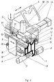
- the device for processing rod-shaped workpieces is in the embodiment selected here as a machining center Processing of profiles 1 for window or Door frame trained.
- the device has a (only indicated) underframe 16 on which the receptacle 2 is arranged for the profiles 1.
- At one end of the Profiles 1 attack two stationary clamping elements 3, which can be seen somewhat more precisely from FIG. 3.
- the processing unit 4 in the case shown here Embodiment a cutter 5 for milling a Long slot 17 ( Figure 3).
- the processing unit 4 can be moved in three directions, namely in the longitudinal direction, in the transverse direction and in the vertical direction with respect to the editing profile 1; this is indicated by arrows in Figure 3 indicated.
- the control of the processing unit 4 can using a PLC, CNC or similar control to get the desired milling or drilling pattern.
- the clamping elements 6, 7 and 8 have in the shown here Embodiment several rollers 12 arranged one behind the other on which a belt 13 rotates.
- the band 13 can, for example. made of plastic, rubber or a chain with one abrasion-resistant plastic or rubber covering can be formed.
- the clamping elements 6 and 7 and 8 brought into profile or clamping position on the profile 1.
- pneumatically actuated clamping cylinders 14 and 15 are provided.
- the Processing unit 4 in the processing shown here in Move longitudinal direction with respect to profile 1.
- By using a belt that rolls on the profile 1 13 it does not come about despite the high clamping forces unwanted impressions or damage to the profile.
- the arrangement is such that the clamping elements 6 and 7 to lie above the stationary clamping units 3 come so that the workpiece 1 in the end region of the Fixed clamping can be processed without the Clamping elements 3 must be removed.
- FIG. 3 shows only a detail of the processing unit 4 shown with clamping elements 6, 7, 8. It goes without saying it is also possible that these clamping elements, as shown in Figure 1 seen on both sides of the processing tool 5 on the Processing unit 4 are provided.
- the tensioning element 8 acting on the profile 1 from above is preferably spring-loaded, in order to achieve additional profile tolerances balance.
- the tensioning elements 6, 7 and 8 together with the support 2 with respect to the processing unit 4 are rotatable, so that not only one Machining of the workpiece 1 on the top 11 accordingly the figures, but also on the side walls 9, 10 or the bottom is enabled. This can be done, for example achieve that the support member 18 with pad 2 compared to the Processing unit 4 is rotatable.
Abstract
Description
Die Erfindung bezieht sich auf eine Vorrichtung zum Bearbeiten eines stabförmigen Werkstückes, insbesondere von Fenster- oder Türprofilen, mit einer Aufnahme für das Werkstück, mit wenigstens einer stationären Spanneinrichtung zum Festlegen des Werkstücks auf oder in der Aufnahme, mindestens einer entlang dem zu bearbeitenden Werkstück verfahrbaren, wenigstens ein Bearbeitungswerkzeug aufweisenden Bearbeitungseinheit.The invention relates to a device for processing a rod-shaped workpiece, in particular window or door profiles, with a holder for the workpiece, with at least one stationary clamping device for fixing the workpiece or in the receptacle, at least one along the workpiece to be machined movable, having at least one processing tool Processing unit.
Zur Bearbeitung von stabförmigen Werkstücken, wie beispielsweise für Fenster- oder Türrahmen, insbesondere zum Einarbeiten von Bohrungen, Nuten, Schlitzen oder dergleichen, wird bei den bekannten Vorrichtungen das Profil an mehreren Stellen, beispielsweise mittels Spannzylindern, eingespannt, wobei die Bearbeitungseinheit relativ zu dem Werkstück verfahrbar ist. Die mehreren Einspannelemente sind deshalb erforderlich, um eine ordnungsgemäße Positionierung und Halterung des Werkstückes zu gewährleisten. Nachteilig hierbei ist die Vielzahl der Spannelemente, was einen erheblichen Kostenfaktor bedeutet. Ein weiterer Nachteil ist, daß die ortsfesten Spannelemente nicht immer genau in dem Bereich an dem Profil angreifen, in welcher die Bearbeitung stattfindet, so daß es zu Vibrationen des Werkstückes bei der Bearbeitung und damit zu Ungenauigkeiten, Geräuschentwicklungen kommen kann. Zudem ist durch Vibrationen des Werkstückes die Vorschubgeschwindigkeit bei der Bearbeitung begrenzt.For machining rod-shaped workpieces, such as for example for window or door frames, especially for Incorporation of bores, grooves, slots or the like, is the profile of several in the known devices Places, for example by means of clamping cylinders, the machining unit relative to the workpiece is movable. The multiple clamping elements are therefore required for proper positioning and To ensure that the workpiece is held. The disadvantage here is the multitude of clamping elements, which is a considerable one Cost factor means. Another disadvantage is that the stationary clamping elements are not always exactly in the area attack the profile in which the processing takes place, so that the workpiece vibrates during machining and this leads to inaccuracies and noise can. In addition, the vibration of the workpiece Feed rate limited during processing.
Eine Vorrichtung mit den eingangs genannten Merkmalen ist bereits aus der DE 30 08 520 A1 bekannt. Bei dieser Vorrichtung handelt es sich um eine Fräsmaschine zum Einfräsen von Ausnehmungen in Fenster- oder Türrahmen, mit einem Frässupport, der mindestens eine Frässpindel und einen diese antreibenden Antriebsmotor trägt. Dabei ist eine Führungseinrichtung für eine Relativbewegung zwischen der Frässpindel und dem Werkstück vorgesehen. Der Frässupport ist mit mindestens einer Stützfläche verbunden, die das Werkstück in der Nähe der Bearbeitungsstelle stützt. Die Stützflächen werden durch in einem Anschlaghalter bevorzugt verstellbar angebrachte Stützanschläge gebildet, welche als Stützrollen ausgeführt sein können. Die bekannte Vorrichtung weist eine Aufspannfläche auf, auf der das zu bearbeitende Werkstück mittels zweier stationärer Spanneinrichtungen festgelegt ist. Am Frässupport sind zwei Anschläge angebracht, wobei je nach Positionierung des Frässupports der eine oder der andere Stützanschlag sich an einer Seitenwand des zu bearbeitenden Werkstückes abstützt. Durch diese Maßnahme soll eine Vibration des beidseitig eingespannten dünnwandigen Profilstabes während der Fräsbearbeitung verhindert werden. Zugleich führen der eine oder der andere Stützanschlag den Fräser bei der Bewegung des Frässupports in Längsrichtung des zu bearbeitenden Werkstückes.A device with the features mentioned above is already known from DE 30 08 520 A1. At this The device is a milling machine for milling of recesses in window or door frames, with one Milling support, the at least one milling spindle and one driving drive motor carries. There is one Guide device for a relative movement between the Milling spindle and the workpiece provided. The milling support is connected to at least one support surface that the workpiece supports near the processing point. The support surfaces are preferably adjustable by in a stop holder attached support stops formed, which serve as support rollers can be executed. The known device has a Clamping surface on which the workpiece to be machined is fixed by means of two stationary clamping devices. Two stops are attached to the milling support, depending on Positioning the milling support one way or the other Support stop itself on a side wall of the to be machined Supports the workpiece. This measure is intended to cause vibration of the thin-walled profile bar clamped on both sides during milling can be prevented. At the same time lead one or the other support stop the router while moving the milling support in the longitudinal direction of the one to be machined Workpiece.
Davon ausgehend liegt der Erfindung die Aufgabe zugrunde, eine Vorrichtung der eingangs genannten Art dahingehend weiterzuentwickeln, daß unter Verzicht auf eine Vielzahl von Spannelementen eine präzise, rasche und geräuscharme Bearbeitung erreicht ist.Based on this, the invention is based on the object Device of the type mentioned in this regard to further develop that without a large number of Clamping elements a precise, quick and low-noise Processing is reached.
Diese Aufgabe wird bei der Vorrichtung mit den eingangs genannten Merkmalen gelöst durch eine entlang dem Werkstück verfahrbare Spannvorrichtung mit wenigstens zwei Spannelementen zum Einspannen des Werkstückes, die mit einer Vorschubbewegung zumindest während der Bearbeitung eines Längsschlitzes an dem zu bearbeitenden Werkstück gleiten oder abrollen sowie mit Mitteln zum Zustellen und Wegfahren wenigstens eines der Spannelemente an das bzw. von dem Werkstück, wobei die Mittel an wenigstens einem der wenigstens zwei Spannelemente vorgesehen sind. Hierdurch ist eine präzise Bearbeitung der Werkstücke erreicht. Es bedarf lediglich der Einspannung des Werkstückes mittels wenigstens einem stationären beziehungsweise ortsfesten Spannelement in einem Endbereich des zu bearbeitenden Profils. Durch die weitere Einspannung des Werkstückes mit der verfahrbaren Spannvorrichtung im Bereich des wenigstens einen Bearbeitungswerkzeuges sind Vibrationen des Werkstückes und damit auch eine Geräuschentwicklung vermieden, ebenso wie dadurch eine hohe Vorschubgeschwindigkeit erreicht ist.This task is the device with the above mentioned features solved by a movable along the workpiece Clamping device with at least two clamping elements for clamping the workpiece with a feed movement at least during the machining of a longitudinal slot slide or roll on the workpiece to be machined and with means for delivering and moving away at least one of the clamping elements to or from the workpiece, the Means on at least one of the at least two clamping elements are provided. This makes it precise Machining of the workpieces achieved. All it takes is the Clamping the workpiece using at least one stationary or stationary clamping element in one End area of the profile to be processed. By the further Clamping the workpiece with the movable one Clamping device in the area of at least one Machining tools are vibrations of the workpiece and thus also avoiding noise, as well a high feed rate is achieved.
In einer ersten besonderen Ausführungsform ist es vorgesehen, daß wenigstens die Spannelemente zusammen mit der Bearbeitungseinheit beziehungsweise dem Bearbeitungswerkzeug verfahrbar sind, so daß es nur eines einzähligen Antriebes für das Verfahren des wenigstens einen Spannelementes und Bearbeitungseinheit bedarf.In a first particular embodiment, it is provided that that at least the clamping elements together with the Processing unit or the processing tool Are movable so that there is only a single drive for the method of the at least one tensioning element and Processing unit required.
Bevorzugt ist nach der Erfindung an gegenüberliegenden Seitenwandungen des in Bearbeitungsposition befindlichen Werkstückes jeweils wenigstens ein Spannelement vorgesehen, wodurch an jeder Position der gegenüberliegenden Seitenwandungen des Werkstückes eine Bearbeitung durchgeführt werden kann.Is preferred according to the invention on opposite Sidewalls of the one in processing position Workpiece each provided at least one clamping element, whereby at every position the opposite Side walls of the workpiece are processed can be.
Auch kann es sich nach der Erfindung empfehlen, ein weiteres auf der Oberseite des in Bearbeitungsstellung in der Aufnahme befindlichen Werkstückes angreifendes, das Werkstück auf die Aufnahme pressendes Spannelement vorzusehen, wodurch eine allseitige Einspannung des Werkstückes im Bereich der Bearbeitungseinheit erreicht ist.It can also be recommended according to the invention, another on the top of the in processing position in the recording located workpiece attacking the workpiece on the Provide pressing clamping element, whereby a all-round clamping of the workpiece in the area of Processing unit is reached.
Weiterhin empfiehlt es sich nach der Erfindung, daß wenigstens eines der Spannelemente, insbesondere das, welches auf der Oberseite des in Bearbeitungsposition befindlichen Werkstückes, oder dasjenige welches auf der der Referenzlage des Werkstückes abgewandten Seitenwandung angreift, mittels einer elastischen Kraft auf beziehungsweise an das Werkstück gedrückt ist, so daß etwaige Profiltoleranzen ausgeglichen werden können.Furthermore, it is recommended according to the invention that at least one of the clamping elements, in particular that which is on the Top of the one in processing position Workpiece, or that on the of the reference position side wall facing away from the workpiece, by means of an elastic force on or on the workpiece is pressed so that any profile tolerances are compensated can be.
Als verfahrbare Spannelemente kommen beispielsweise Plattenelemente in Betracht, welche beim Verfahren der Bearbeitungseinheit an den äußeren Wandungen des Profils entlang gleiten.For example, movable clamping elements Plate elements into consideration, which in the process of Processing unit on the outer walls of the profile slide along.
Vorteilhafterweise werden als Spannelemente nach einer Ausgestaltung der Erfindung mindestens eine an dem Werkstück beim Verfahren der Bearbeitungseinheit abrollende Walze, Rolle oder dergleichen Abrollelement vorgesehen, so daß ein kontinuierliches, ruckfreies Verschieben der Spannelemente an den Profilen gewährleistet ist.Advantageously, as clamping elements after a Embodiment of the invention at least one on the workpiece roller rolling in the process of the processing unit, roller or the like rolling element is provided so that a continuous, jerk-free displacement of the clamping elements the profiles is guaranteed.
Insbesondere empfiehlt es sich nach der Erfindung, daß die Spannelemente mittels einem um Walzen, Rollen oder dergleichen Abrollelemente umlaufendes Band an dem Werkstück beim Verfahren der Bearbeitungseinheit abrollen. Dabei kann das Band aus Kunststoff, Gummi oder einer Kette mit einem, vorzugsweise abriebfesten Kunststoff- oder Gummibelag bestehen, so daß Werkstückbeschädigungen vermieden sind.In particular, it is recommended according to the invention that the Clamping elements by means of rollers, rollers or the like Roll-off conveyor belt on the workpiece at Unroll the processing unit. It can Band made of plastic, rubber or a chain with a preferably abrasion-resistant plastic or rubber covering exist so that workpiece damage is avoided.
Um ein einfaches Einlegen der zu bearbeitenden Profile zu erreichen, ist wenigstens eines der Spannelemente an das Werkstück zustellbar und von diesem wegfahrbar, was mittels einer Kolben-Zylinder-Anordnung erfolgen kann. Dabei kann die Kolben-Zylinder-Anordnung gleichzeitig zum Erzeugen eines definierten Anpreßdruckes auf das Profil eingesetzt werden.To easily insert the profiles to be processed achieve is at least one of the clamping elements to the Workpiece can be delivered and moved away from it by means of a piston-cylinder arrangement can take place. The Piston-cylinder arrangement simultaneously to generate one defined contact pressure on the profile.
Im Falle, daß an gegenüberliegenden Seitenwandungen des Werkstückes angreifende Spannelemente vorgesehen sind, sollte wenigstens eines der Spannelemente in eine definiertere Lage verfahrbar sein, welche einen Referenzpunkt für das Werkstück beziehungsweise für die Bearbeitungseinheit bildet. In the event that on opposite side walls of the Clamping elements attacking the workpiece should be provided at least one of the clamping elements in a more defined position be movable, which is a reference point for the workpiece or for the processing unit.
Besonders vorteilhaft es ist auch, wenn die verfahrbaren Spannelemente in einer von den ortsfesten Spannelementen verschiedenen Ebene zu liegen kommen. Hierdurch ist eine Bearbeitung des Profiles auch in dessen Endbereichen möglich, ohne daß die ortsfesten Spannelemente entfernt werden müßten.It is also particularly advantageous if the movable Clamping elements in one of the fixed clamping elements come to different levels. This is one Processing of the profile also possible in its end areas, without having to remove the stationary clamping elements.
Selbstverständlich ist es nach der Erfindung auch möglich, daß beidseitig der Bearbeitungswerkzeuge der Bearbeitungseinheit verfahrbare Spannelemente vorgesehen sind.Of course, it is also possible according to the invention that on both sides of the processing tools of the processing unit movable clamping elements are provided.
Schließlich ist es nach der Erfindung vorgesehen, daß wenigstens eines der Spannelemente zusammen mit der Aufnahme für das Werkstück verdrehbar bezüglich der Bearbeitungseinheit ausgebildet ist. Hierdurch ist eine allseitige Bearbeitung des Werkstückes ermöglicht.Finally, it is provided according to the invention that at least one of the clamping elements together with the receptacle rotatable for the workpiece with respect to the processing unit is trained. As a result, all-round processing of the Workpiece.
Weitere Vorteile und Anwendungsmöglichkeiten der vorliegenden Erfindung ergeben sich aus der nachfolgenden Beschreibung eines Ausführungsbeispieles anhand der Zeichnung.Further advantages and possible uses of the present Invention result from the following description an embodiment with reference to the drawing.
Es zeigen:
Figur 1- eine schematische Seitenansicht einer erfindungsgemäßen Bearbeitungseinheit mit verfahrbaren Spannelementen,
Figur 2- eine schematische Darstellung der
Referenzpunkteinstellung der Vorrichtung gemäß
Figur 1 und Figur 3- eine perspektivische Ansicht der
Bearbeitungseinheit, ähnlich derjenigen gemäß
Figur 1.
- Figure 1
- 2 shows a schematic side view of a processing unit according to the invention with movable clamping elements,
- Figure 2
- a schematic representation of the reference point setting of the device according to Figure 1 and
- Figure 3
- 3 shows a perspective view of the processing unit, similar to that according to FIG. 1.
Die Vorrichtung zum Bearbeiten von stabförmigen Werkstücken ist bei dem
hier gewählten Ausführungsbeispiel als Bearbeitungszentrum zur
Bearbeitung von Profilen 1 für Fenster- oder
Türrahmen ausgebildet. Die Vorrichtung weist ein (nur
angedeutetes) Untergestell 16 auf, an welchem die Aufnahme 2
für die Profile 1 angeordnet ist. An dem einen Endbereich des
Profiles 1 greifen zwei stationäre Spannelemente 3 an, welche
etwas genauer aus Figur 3 zu ersehen ist.The device for processing rod-shaped workpieces is in the
embodiment selected here as a machining center
Processing of
Die Bearbeitungseinheit 4 weist bei der hier dargestellten
Ausführungsform einen Fräser 5 zum Einfräsen eines
Langschlitzes 17 (Figur 3) auf. Selbstverständlich ist es auch
möglich, daß an der Bearbeitungseinheit 4 Bohrer,
Gewindebohrer, Sägen, Scheibenfräser oder dergleichen
Bearbeitungswerkzeuge angeordnet sind. Die Bearbeitungseinheit
4 ist in drei Richtungen verfahrbar, nämlich in Längsrichtung,
in Querrichtung und in vertikaler Richtung bzgl. des zu
bearbeitenden Profils 1; dies ist durch Pfeile in Figur 3
angedeutet. Die Steuerung der Bearbeitungseinheit 4 kann
mittels einer SPS-, CNC- oder einer ähnlichen Steuerung
erfolgen, um das gewünschte Fräs- oder Bohrbild zu erhalten.The
Bei einem Verfahren der Bearbeitungseinheit 4 ist das Werkstück
1 in unmittelbarer Nähe des Bearbeitungswerkzeuges 5 mittels
verfahrbarer Spannelemente 6, 7 und 8 eingespannt. Diese
Spannelemente 6, 7, 8 sind bei dem hier gewählten
Ausführungsbeispiel fest mit der Bearbeitungseinheit 4 über ein
Trägerteil 18 verbunden.In a process of the
Die Spannelemente 6, 7 und 8 weisen bei der hier gezeigten
Ausführungsform mehrere hintereinander angeordnete Rollen 12
auf, auf welchen ein Band 13 umläuft. Das Band 13 kann bspw.
aus Kunststoff, Gummi oder auch aus einer Kette mit einem
abriebfesten Kunststoff- oder Gummi-Belag gebildet sein. Vor
dem eigentlichen Bearbeiten werden die Spannelemente 6 und 7
und 8 in Anlage- bzw. Spannstellung an das Profil 1 gebracht.
Hierfür sind, bspw. pneumatisch betätigbare Spannzylinder 14
und 15 vorgesehen.The
Das Einspannen des Werkstückes 1 mittels den seitlichen
Spannelementen 6, 7 erfolgt derart, daß, wie in Figur 2
angedeutet, zur Erzeugung eines Referenzpunktes 0 für das
Bearbeitungswerkzeug 5 bzw. die Bearbeitungseinheit 4 zunächst
das Spannelement 7 in eine vorgegebene Referenzlage 0 an das
Werkstück 1 gefahren wird. Selbstverständlich ist es auch
möglich, daß das eine Spannelement 7 feststehend angeordnet und
bzgl. des Referenzpunktes 0 ausgerichtet ist. Danach wird mit
Hilfe der Kolben-Zylinder-Einheit 14 das Spannelement 6 gegen
das Profil 1 gepreßt, so daß sich das zu bearbeitende Profil 1
in Preßstellung zwischen den Spannelementen 6 und 7 befindet.
Hierdurch ist der Referenzpunkt 0 für die Bearbeitungseinheit 4
geschaffen. Gleichzeitig oder während dieser Spanneinstellung
wird der Spannzylinder 15 betätigt, so daß auch das obere
Spannelement 8 auf das Profil 1 drückt und es auf die Aufnahme
2 preßt.Clamping the
Während der Bearbeitung des Längsschlitzes 17 wird die
Bearbeitungseinheit 4 bei der hier dargestellten Bearbeitung in
Längsrichtung bzgl. des Profiles 1 verfahren. Dabei rollen die
Spannelemente 6, 7 und 8 mit ihren Rollen 12 bzw. mit ihrem
Band 13 auf bzw. an dem Werkstück 1 ab, so daß es während der
Bearbeitung präzise gehalten ist. Hierdurch werden Bohr- oder
Fräsbilder von hoher Präzision erzielt, da das Werkstück 1 in
unmittelbar Nähe des Bearbeitungswerkzeuges 5 fest eingespannt
ist. Durch den Einsatz eines an dem Profil 1 abrollenden Bandes
13 kommt es trotz hoher Einspannkräfte auch nicht zu
unerwünschten Impressionen oder Beschädigungen an dem Profil.
Weiterhin ist eine geräuscharme Bearbeitung mit hoher
Vorschubgeschwindigkeit erreicht.During the processing of the
Weiterhin ist die Anordnung so getroffen, daß die Spannelemente
6 und 7 oberhalb der stationären Spanneinheiten 3 zu liegen
kommen, so daß das Werkstück 1 auch im Endbereich der
ortsfesten Einspannung bearbeitet werden kann, ohne daß die
Spannelemente 3 entfernt werden müssen.Furthermore, the arrangement is such that the
In Figur 3 ist lediglich ein Detail der Bearbeitungseinheit 4
mit Spannelementen 6, 7, 8 dargestellt. Selbstverständlich ist
es auch möglich, daß diese Spannelemente, wie aus Figur 1 zu
ersehen, beidseitig des Bearbeitungswerkzeuges 5 an der
Bearbeitungseinheit 4 vorgesehen sind. FIG. 3 shows only a detail of the
Das von oben auf das Profil 1 wirkende Spannelement 8 ist
vorzugsweise federnd gelagert, um zusätzlich Profiltoleranzen
auszugleichen.The
Auch kann es sich auch empfehlen, daß die Spannelemente 6, 7
und 8 zusammen mit der Auflage 2 bzgl. der Bearbeitungseinheit
4 verdrehbar ausgebildet sind, so daß nicht nur eine
Bearbeitung des Werkstückes 1 auf der Oberseite 11 entsprechend
den Figuren, sondern auch an den Seitenwandungen 9, 10 oder an
der Unterseite ermöglicht ist. Dies läßt sich bspw. dadurch
erreichen, daß das Trägerteil 18 mit Auflage 2 gegenüber der
Bearbeitungseinheit 4 verdrehbar ausgebildet ist. It can also be recommended that the
- 1 -1 -
- Werkstückworkpiece
- 2 -2 -
- Aufnahmeadmission
- 3 -3 -
- Spanneinrichtung, SpannelementClamping device, clamping element
- 4 -4 -
- BearbeitungseinheitProcessing unit
- 5 -5 -
- Bearbeitungswerkzeug, FräserMachining tool, milling cutter
- 6 -6 -
- SpannelementClamping element
- 7 -7 -
- SpannelementClamping element
- 8 -8th -
- SpannelementClamping element
- 9 -9 -
- SeitenwandungSide wall
- 10 -10 -
- SeitenwandungSide wall
- 11 -11 -
- OberseiteTop
- 12 -12 -
- Rollerole
- 13 -13 -
- Bandtape
- 14 -14 -
- Kolben-Zylinder-Anordnung, SpannzylinderPiston-cylinder arrangement, clamping cylinder
- 15 -15 -
- Kolben-Zylinder-AnordnungPiston-cylinder arrangement
- 16 -16 -
- UntergestellUnderframe
- 17 -17 -
- LängsschlitzLongitudinal slot
- 18 -18 -
- TrägerteilCarrier part
- 0 -0 -
- ReferenzpunktReference point
Claims (15)
- Device for the processing of a rod-shaped workpiece, especially of window and door profile members (1), with a mount (2) for the workpiece, with at least one stationary clamping device (3) for fixing the workpiece on or in the mount (2), and with at least one processing unit (4) which is movable along the workpiece to be processed and comprises at least one processing tool (5), characterised by a clamping device, which is movable along the workpiece, with at least two clamping elements (6, 7, 8) for clamping in the workpiece which, by a feeding movement, slide or roll against the workpiece, which is to be processed, at least during the processing of a longitudinal slot (17), as well as with means for taking at least one of the clamping elements (6, 7, 8) to and moving that away from the workpiece, wherein the means are provided at at least one of the at least two clamping elements (6, 7, 8).
- Device according to claim 1, characterised in that the clamping elements (6, 7; 8) are movable together with the processing unit (4).
- Device according to claim 1 or 2, characterised in that at least one clamping element (6, 7; 8) is constructed as a support, which is movable with the processing unit, for the workpiece.
- Device according to one of the preceding claims, characterised in that the at least two clamping elements (6, 7, 8) are arranged opposite one another.
- Device according to one of the preceding claims, characterised in that at least one of the clamping elements (6, 7, 8) is provided as a clamping element (8) engaging on the upper side (11) of the workpiece (1), which in the processing position is disposed at or in the mount (2), and pressing the workpiece (1) onto the mount (2).
- Device according to one of the preceding claims, characterised in that at least one of the clamping elements (6, 7; 8) is pressed onto or against the workpiece (1) by means of a resilient force.
- Device according to one of the preceding claims, characterised in that at least one of the clamping elements (6, 7; 8) comprises a plate element sliding along the workpiece (1) during displacement of the processing unit (4).
- Device according to one of claims 1 to 6, characterised in that at least one of the clamping elements (6, 7; 8) comprises at least one roll, roller (12) or like rollable element rolling against the workpiece (1) during movement of the processing unit (4).
- Device according to one of claims 1 to 6, characterised in that at least one of the clamping elements (6, 7; 8) rolls against the workpiece (1) by means of a belt (13), which runs around rolls, rollers (12) or like rollable elements, during movement of the processing unit (4).
- Device according to claim 9, characterised in that the belt (13) consists of synthetic material, rubber or a chain with a preferably wear-resistant synthetic material or rubber coating.
- Device according to one of the preceding claims, characterised in that at least one clamping element (6, 7; 8) is feedable by a piston-cylinder arrangement (14, 15) to the workpiece (1) and movable away from this.
- Device according to one of the preceding claims, characterised in that in the case of clamping elements (6, 7) oppositely engaging the workpiece (1) at least one clamping element (7) is movable into a reference position with respect to the workpiece (1) or for the processing unit (4).
- Device according to one of the preceding claims, characterised in that at least one of the clamping elements (6, 7; 8) comes to lie in a plane different from the stationery clamping elements (3).
- Device according to one of the preceding claims, characterised in that movable clamping elements (6, 7; 8) are arranged on both sides of the at least one processing tool (5) of the processing unit (4).
- Device according to one of the preceding claims, characterised in that at least one of the clamping elements (6, 7; 8) is constructed to be rotatable relative to the processing unit (4) together with the mount (2) for the workpiece (1).
Applications Claiming Priority (2)
| Application Number | Priority Date | Filing Date | Title |
|---|---|---|---|
| DE4439101 | 1994-11-04 | ||
| DE4439101 | 1994-11-04 |
Publications (2)
| Publication Number | Publication Date |
|---|---|
| EP0710524A1 EP0710524A1 (en) | 1996-05-08 |
| EP0710524B1 true EP0710524B1 (en) | 2000-08-09 |
Family
ID=6532291
Family Applications (1)
| Application Number | Title | Priority Date | Filing Date |
|---|---|---|---|
| EP95117414A Expired - Lifetime EP0710524B1 (en) | 1994-11-04 | 1995-11-06 | Device for machining workpieces, in particular for window or door profiles |
Country Status (3)
| Country | Link |
|---|---|
| EP (1) | EP0710524B1 (en) |
| AT (1) | ATE195278T1 (en) |
| DE (1) | DE59508622D1 (en) |
Families Citing this family (1)
| Publication number | Priority date | Publication date | Assignee | Title |
|---|---|---|---|---|
| DE10030865B4 (en) * | 2000-06-23 | 2004-09-02 | Eisenbach, Bernhard, Dipl.-Ing. | Clamping device for workpieces, such as window or door profiles or other elongated profiles |
Family Cites Families (2)
| Publication number | Priority date | Publication date | Assignee | Title |
|---|---|---|---|---|
| DE3008520A1 (en) * | 1980-03-06 | 1981-09-17 | Bernhard 6259 Brechen Eisenbach | Window frame recess milling machine - has support joined to work supporting faces near machining point |
| DE4204519A1 (en) * | 1992-02-15 | 1993-08-19 | Bernhard Eisenbach | DEVICE FOR MULTI-SIDED MACHINING OF HOLLOW PROFILES |
-
1995
- 1995-11-06 EP EP95117414A patent/EP0710524B1/en not_active Expired - Lifetime
- 1995-11-06 AT AT95117414T patent/ATE195278T1/en not_active IP Right Cessation
- 1995-11-06 DE DE59508622T patent/DE59508622D1/en not_active Expired - Fee Related
Also Published As
| Publication number | Publication date |
|---|---|
| DE59508622D1 (en) | 2000-09-14 |
| EP0710524A1 (en) | 1996-05-08 |
| ATE195278T1 (en) | 2000-08-15 |
Similar Documents
| Publication | Publication Date | Title |
|---|---|---|
| EP1281491B1 (en) | Apparatus and method for machining wooden, plastic or similar workpieces | |
| EP1784291B1 (en) | Machining device, particularly plate cutting device | |
| DE1427765C3 (en) | Guide device for a concrete cutting machine | |
| EP3639971A1 (en) | Method for machining elongated workpieces made of wood, plastic and the like, and machine for carrying out said method | |
| EP3853415B1 (en) | Device for re-profiling and deburring rails | |
| DE102005020477A1 (en) | Processing unit on a continuous woodworking machine | |
| EP0602308B1 (en) | Device for working the side edges of continuously fed panel shaped workpieces | |
| EP0330970A2 (en) | Device for positioning curved frame members and milling trapezoidal grooves in said frame members | |
| DE4419963C1 (en) | Continuous loop grinding machine for chamfering both sides of glass plate edge | |
| EP0710524B1 (en) | Device for machining workpieces, in particular for window or door profiles | |
| DE2726382C3 (en) | Device for drilling and cutting or milling a component from a plate-shaped workpiece made of wood or the like | |
| DE3103722C2 (en) | Stop device for woodworking machines | |
| DE10047385C2 (en) | Method and device for machining continuously moving workpieces | |
| DE10011754B4 (en) | Device for low-vibration holding of flat workpieces on a cutting machine | |
| DE202004020654U1 (en) | Folding bending press esp. for sheet metal profiles e.g. shelf boards has hold- down strips of different lengths on rotating roller above bending table, for easy adjustment to different profile widths | |
| EP0571816B1 (en) | Veneer application machine with trimming device | |
| WO2000009303A1 (en) | Aggregate for mounting an edging which comprises a fastening element | |
| DE4041657A1 (en) | Circular saw | |
| DE10033705C2 (en) | Device for processing elongated workpieces, in particular window and door parts | |
| DE19721521C2 (en) | Numerically controlled tenoning machine | |
| DE3933863A1 (en) | NC slideway-type precision grinding machine - has grinding head with additional axes of movement to facilitate NC grinding of curved ways | |
| DE3546864C2 (en) | Sheet metal bending press | |
| EP1437196B1 (en) | Device for working upon an hollow profil along a plurality of his sides | |
| DE3317026C1 (en) | Copy-milling device for milling fitting recesses in door and window sections | |
| DE19703240B4 (en) | Device for handling and processing preferably plate-shaped workpieces |
Legal Events
| Date | Code | Title | Description |
|---|---|---|---|
| PUAI | Public reference made under article 153(3) epc to a published international application that has entered the european phase |
Free format text: ORIGINAL CODE: 0009012 |
|
| AK | Designated contracting states |
Kind code of ref document: A1 Designated state(s): AT BE DE FR GB |
|
| 17P | Request for examination filed |
Effective date: 19960327 |
|
| 17Q | First examination report despatched |
Effective date: 19980323 |
|
| GRAG | Despatch of communication of intention to grant |
Free format text: ORIGINAL CODE: EPIDOS AGRA |
|
| GRAG | Despatch of communication of intention to grant |
Free format text: ORIGINAL CODE: EPIDOS AGRA |
|
| GRAG | Despatch of communication of intention to grant |
Free format text: ORIGINAL CODE: EPIDOS AGRA |
|
| GRAH | Despatch of communication of intention to grant a patent |
Free format text: ORIGINAL CODE: EPIDOS IGRA |
|
| GRAH | Despatch of communication of intention to grant a patent |
Free format text: ORIGINAL CODE: EPIDOS IGRA |
|
| GRAA | (expected) grant |
Free format text: ORIGINAL CODE: 0009210 |
|
| AK | Designated contracting states |
Kind code of ref document: B1 Designated state(s): AT BE DE FR GB |
|
| REF | Corresponds to: |
Ref document number: 195278 Country of ref document: AT Date of ref document: 20000815 Kind code of ref document: T |
|
| GBT | Gb: translation of ep patent filed (gb section 77(6)(a)/1977) |
Effective date: 20000809 |
|
| REF | Corresponds to: |
Ref document number: 59508622 Country of ref document: DE Date of ref document: 20000914 |
|
| ET | Fr: translation filed | ||
| PLBE | No opposition filed within time limit |
Free format text: ORIGINAL CODE: 0009261 |
|
| STAA | Information on the status of an ep patent application or granted ep patent |
Free format text: STATUS: NO OPPOSITION FILED WITHIN TIME LIMIT |
|
| 26N | No opposition filed | ||
| REG | Reference to a national code |
Ref country code: GB Ref legal event code: IF02 |
|
| PGFP | Annual fee paid to national office [announced via postgrant information from national office to epo] |
Ref country code: AT Payment date: 20081114 Year of fee payment: 14 |
|
| PGFP | Annual fee paid to national office [announced via postgrant information from national office to epo] |
Ref country code: FR Payment date: 20081113 Year of fee payment: 14 |
|
| PGFP | Annual fee paid to national office [announced via postgrant information from national office to epo] |
Ref country code: DE Payment date: 20081130 Year of fee payment: 14 |
|
| PGFP | Annual fee paid to national office [announced via postgrant information from national office to epo] |
Ref country code: GB Payment date: 20081117 Year of fee payment: 14 |
|
| PGFP | Annual fee paid to national office [announced via postgrant information from national office to epo] |
Ref country code: BE Payment date: 20090126 Year of fee payment: 14 |
|
| BERE | Be: lapsed |
Owner name: *EISENBACH BERND Effective date: 20091130 |
|
| GBPC | Gb: european patent ceased through non-payment of renewal fee |
Effective date: 20091106 |
|
| REG | Reference to a national code |
Ref country code: FR Ref legal event code: ST Effective date: 20100730 |
|
| PG25 | Lapsed in a contracting state [announced via postgrant information from national office to epo] |
Ref country code: AT Free format text: LAPSE BECAUSE OF NON-PAYMENT OF DUE FEES Effective date: 20091106 |
|
| PG25 | Lapsed in a contracting state [announced via postgrant information from national office to epo] |
Ref country code: FR Free format text: LAPSE BECAUSE OF NON-PAYMENT OF DUE FEES Effective date: 20091130 Ref country code: BE Free format text: LAPSE BECAUSE OF NON-PAYMENT OF DUE FEES Effective date: 20091130 |
|
| PG25 | Lapsed in a contracting state [announced via postgrant information from national office to epo] |
Ref country code: DE Free format text: LAPSE BECAUSE OF NON-PAYMENT OF DUE FEES Effective date: 20100601 |
|
| PG25 | Lapsed in a contracting state [announced via postgrant information from national office to epo] |
Ref country code: GB Free format text: LAPSE BECAUSE OF NON-PAYMENT OF DUE FEES Effective date: 20091106 |