EP0710397B1 - High-pressure metal halide lamp - Google Patents
High-pressure metal halide lamp Download PDFInfo
- Publication number
- EP0710397B1 EP0710397B1 EP95912393A EP95912393A EP0710397B1 EP 0710397 B1 EP0710397 B1 EP 0710397B1 EP 95912393 A EP95912393 A EP 95912393A EP 95912393 A EP95912393 A EP 95912393A EP 0710397 B1 EP0710397 B1 EP 0710397B1
- Authority
- EP
- European Patent Office
- Prior art keywords
- lamp
- ceramic
- end wall
- face
- wall portion
- Prior art date
- Legal status (The legal status is an assumption and is not a legal conclusion. Google has not performed a legal analysis and makes no representation as to the accuracy of the status listed.)
- Expired - Lifetime
Links
- 229910001507 metal halide Inorganic materials 0.000 title claims abstract description 13
- 150000005309 metal halides Chemical class 0.000 title claims abstract description 13
- 239000000919 ceramic Substances 0.000 claims abstract description 25
- PNEYBMLMFCGWSK-UHFFFAOYSA-N Alumina Chemical compound [O-2].[O-2].[O-2].[Al+3].[Al+3] PNEYBMLMFCGWSK-UHFFFAOYSA-N 0.000 description 6
- 150000004820 halides Chemical class 0.000 description 5
- 238000009877 rendering Methods 0.000 description 5
- 239000004020 conductor Substances 0.000 description 3
- 239000000463 material Substances 0.000 description 3
- 239000000126 substance Substances 0.000 description 3
- 229910052751 metal Inorganic materials 0.000 description 2
- 239000002184 metal Substances 0.000 description 2
- 229910044991 metal oxide Inorganic materials 0.000 description 2
- 150000004706 metal oxides Chemical class 0.000 description 2
- 238000004804 winding Methods 0.000 description 2
- 229910017083 AlN Inorganic materials 0.000 description 1
- PIGFYZPCRLYGLF-UHFFFAOYSA-N Aluminum nitride Chemical compound [Al]#N PIGFYZPCRLYGLF-UHFFFAOYSA-N 0.000 description 1
- PSNPEOOEWZZFPJ-UHFFFAOYSA-N alumane;yttrium Chemical compound [AlH3].[Y] PSNPEOOEWZZFPJ-UHFFFAOYSA-N 0.000 description 1
- 238000010276 construction Methods 0.000 description 1
- 238000010586 diagram Methods 0.000 description 1
- 230000000694 effects Effects 0.000 description 1
- 230000004907 flux Effects 0.000 description 1
- 239000002223 garnet Substances 0.000 description 1
- 239000004615 ingredient Substances 0.000 description 1
- 150000004694 iodide salts Chemical class 0.000 description 1
- 229910052747 lanthanoid Inorganic materials 0.000 description 1
- 150000002602 lanthanoids Chemical class 0.000 description 1
- 238000012423 maintenance Methods 0.000 description 1
- 238000004519 manufacturing process Methods 0.000 description 1
- 150000002739 metals Chemical class 0.000 description 1
- SIWVEOZUMHYXCS-UHFFFAOYSA-N oxo(oxoyttriooxy)yttrium Chemical compound O=[Y]O[Y]=O SIWVEOZUMHYXCS-UHFFFAOYSA-N 0.000 description 1
- 239000011819 refractory material Substances 0.000 description 1
- 229910052594 sapphire Inorganic materials 0.000 description 1
- 239000010980 sapphire Substances 0.000 description 1
- 229910052706 scandium Inorganic materials 0.000 description 1
- 229910052727 yttrium Inorganic materials 0.000 description 1
Images
Classifications
-
- H—ELECTRICITY
- H01—ELECTRIC ELEMENTS
- H01J—ELECTRIC DISCHARGE TUBES OR DISCHARGE LAMPS
- H01J61/00—Gas-discharge or vapour-discharge lamps
- H01J61/82—Lamps with high-pressure unconstricted discharge having a cold pressure > 400 Torr
- H01J61/827—Metal halide arc lamps
-
- H—ELECTRICITY
- H01—ELECTRIC ELEMENTS
- H01J—ELECTRIC DISCHARGE TUBES OR DISCHARGE LAMPS
- H01J61/00—Gas-discharge or vapour-discharge lamps
- H01J61/02—Details
- H01J61/12—Selection of substances for gas fillings; Specified operating pressure or temperature
- H01J61/125—Selection of substances for gas fillings; Specified operating pressure or temperature having an halogenide as principal component
-
- H—ELECTRICITY
- H01—ELECTRIC ELEMENTS
- H01J—ELECTRIC DISCHARGE TUBES OR DISCHARGE LAMPS
- H01J61/00—Gas-discharge or vapour-discharge lamps
- H01J61/02—Details
- H01J61/30—Vessels; Containers
-
- H—ELECTRICITY
- H01—ELECTRIC ELEMENTS
- H01J—ELECTRIC DISCHARGE TUBES OR DISCHARGE LAMPS
- H01J61/00—Gas-discharge or vapour-discharge lamps
- H01J61/02—Details
- H01J61/36—Seals between parts of vessels; Seals for leading-in conductors; Leading-in conductors
- H01J61/366—Seals for leading-in conductors
-
- H—ELECTRICITY
- H01—ELECTRIC ELEMENTS
- H01J—ELECTRIC DISCHARGE TUBES OR DISCHARGE LAMPS
- H01J61/00—Gas-discharge or vapour-discharge lamps
- H01J61/02—Details
- H01J61/30—Vessels; Containers
- H01J61/34—Double-wall vessels or containers
Definitions
- the invention relates to a high-pressure metal halide lamp provided with a discharge vessel which encloses a discharge space, which has a ceramic wall and a filling which comprises besides Hg and a rare gas at least one metal halide, and which is formed from a cylindrical portion with an internal diameter ID closed off at either end by end wall portions, each end wall portion forming an end face of the discharge space while at least one end wall portion is provided with an opening in which a ceramic closing plug is fastened which narrowly encloses over a length 1 a lead-through of a respective electrode provided with an electrode tip and is connected thereto in a gastight manner at the side facing away from the discharge space by means of a ceramic glazing joint, the discharge vessel containing at least two electrodes whose respective tips are situated at a mutual interspacing EA such that the following relation is satisfied ID EA >0.4
- a lamp of the kind mentioned in the opening paragraph is known from EP-A-0 215 524 (PHN 11.485).
- the term "ceramic wall” is here understood to mean a wall of a refractory material such as monocrystalline metal oxide (for example, sapphire), polycrystalline metal oxide (for example, polycrystalline densely sintered aluminium oxide; yttrium-aluminium garnet, or yttrium oxide), and polycrystalline non-oxidic material (for example, aluminium nitride).
- monocrystalline metal oxide for example, sapphire
- polycrystalline metal oxide for example, polycrystalline densely sintered aluminium oxide; yttrium-aluminium garnet, or yttrium oxide
- polycrystalline non-oxidic material for example, aluminium nitride
- the internal diameter is defined in the present description and claims as 1.12 times the square root of the quotient of the volume of the discharge space between the electrode tips and EA.
- the known lamp contains metal halide in excess.
- the metal halide vapour pressure, and thus the partial pressures of the ingredients, are governed by the temperature of the free surface of the excess quantity. This temperature is called cold spot temperature for short (T KP ).
- T KP cold spot temperature for short
- a colour temperature T c in the comparatively low range from approximately 2500 K to 3500 K can be realised with the known lamp with a high luminous efficacy as well as good colour rendering properties.
- a typical characteristic of the lamp of the kind mentioned in the opening paragraph is the comparatively great internal diameter ID of the discharge vessel in relation to the distance between the electrode tips EA.
- One of the results of this is that the location where T KP prevails in lamps having a prior-art discharge vessel is situated near an end face at the discharge vessel wall.
- the electrodes project over some distance into the discharge space, so that there is a considerable tip-to-bottom distance, i.e. the distance between the electrode tip and the location of T KP .
- This is found to result in too low vapour pressures of the halides present in lamps of comparatively low power.
- a reduction of the tip-to-bottom distance gives rise to attacks on the ceramic discharge vessel wall in many cases, in particular on the ceramic closing plug. Fractures also frequently occur in the end wall portion or the closing plug, or both. Chemical attacks and fractures form problems in the realisation of a lamp with a reliable life expectancy.
- a lamp of the kind mentioned in the opening paragraph is for this purpose characterized in that the lamp has a rated power of at most 100 W, in that at least one electrode tip is situated substantially in the adjacent end face, and in that the relevant ceramic closing plug is fastened in the end wall portion in a gastight manner at a distance from the end face.
- the ceramic closing plug does not extend up to the end face but is situated at a distance therefrom, problems involving chemical attacks and fractures are found to be solved. It is an advantage of the invention, accordingly, that a lamp with a very small tip-to-bottom distance can be realised.
- the closing plug is fastened in the end wall portion in a gastight manner at a distance of 1 mm from the end face.
- the gastight fastening between the end wall portion and the closing plug is preferably realised by means of a sintered joint. This type of joint is in fact as resistant to high temperatures and attacks as are the ceramic wall portions themselves.
- the lamp according to the invention preferably complies with the relation 0,9 ⁇ ID EA ⁇ 1.3
- the colour temperature of the light radiated by the lamp will then be substantially the same in all burning positions.
- Suitable metals for forming the metal halide in the discharge vessel are Na, Tl, Sc, Y, and the lanthanides.
- a further improvement of the lamp according to the invention can be realised in that the filling of the discharge vessel also comprises Mg in the form of a halide. This favourably affects the maintenance of a good luminous efficacy during lamp life.
- the filling of the discharge vessel comprises besides Hg and a rare gas one or several halides, usually iodides.
- a suitable rare gas is, for example, Ar which has an ignition-promoting effect.
- a high-pressure metal halide lamp with a ceramic discharge vessel is known per se from EP-A-0 011 993 with a narrowed portion at either end, where electrode tips lie substantially in one plane with the narrowed portion near the relevant electrode.
- the lamp which has a power of less than 250 W, for example, about 100 W, has a considerable interspacing between the electrode tips (2 cm), and as a necessary consequence a comparatively small diameter. This renders the lamp unsuitable for realising a colour temperature in the region between approximately 2500 K and 3500 K with at the same time a comparatively high luminous flux and a good colour rendering.
- a high-pressure metal halide lamp according to the preamble of claim 1 is disclosed in EP-A-0 587 238.
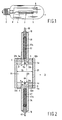
- Fig. 1 shows a high-pressure metal halide lamp provided with a discharge vessel 3 with a ceramic wall which encloses a discharge space 11 and with a filling which comprises besides Hg and a rare gas at least one metal halide.
- the discharge vessel is enclosed in an outer envelope 1 which is provided with a lamp cap 2 at one end.
- the discharge vessel is provided with internal electrodes 4, 5 between which a discharge extends in the operational state of the lamp.
- Electrode 4 is connected to a first electrical contact forming part of the lamp cap 2 via a current conductor 8.
- Electrode 5 is connected to a second electrical contact forming part of the lamp cap 2 via a current conductor 9.
- the discharge vessel shown in more detail in Fig.
- the ceramic closing plugs 34, 35 each narrowly enclose over a length 1 a lead-through 40, 41, 41a, 50, 51, 51a of an associated electrode 4, 5 provided with a tip 4b, 5b.
- the lead-through is connected to the closing plug 34, 35 in a gastight manner by means of a ceramic glazing joint 10 at its side facing away from the discharge space.
- the electrode tips 4b, 5b are situated at a mutual distance EA.
- the lead-throughs each comprise a halide-resistant portion 41, 51 made of, for example, Mo, enclosed by an Mo coil 41a, 51a, and a portion 40, 50 which is fastened to an associated closing plug 34, 35 in a gastight manner by means of the ceramic glazing joint 10.
- Each Mo coil 41a, 51a extends up to the relevant lead-through portion 40, 50.
- the ceramic glazing joint extends over some distance, for example approximately 1 mm, over the Mo coil 41a, 51.
- the portions 40, 50 are made of a metal which has a coefficient of expansion which harmonizes very well with that of the closing plugs.
- Nb is a very suitable material.
- the portions 40, 50 are connected to the current conductors 8, 9 in a manner not shown in detail.
- the lead-through construction described renders it possible to operate the lamp in any burning position as desired.
- Each electrode 4, 5 comprises an electrode rod 4a, 5a which is provided with a winding 4c, 5c near the tip 4b, 5b.
- the electrode tips lie substantially in the planes defined by the end faces 33a, 33b of the end wall portions.
- the closing plugs do not extend up to the end faces but are fastened in the end wall portions in a gastight manner by means of a sintered joint S at a distance a from the end faces.
- the rated lamp power is 70 W.
- the filling of the discharge vessel is 4.4 mg Hg and 8 mg NaJ, TIJ, and (Dy+Ho+Tm)I 3 in a mass ratio of 65:10:25.
- the lamp also contains Ar as an ignition gas.
- the lamp was designed to supply a colour temperature of 3000 K with colour point coordinates (x,y) (437,404) and a general colour rendering index Ra above 80.
- the discharge vessel is made of polycrystalline aluminium oxide, has an internal diameter ID of 6.85 mm and an interspacing between the electrode tips EA of 7 mm.
- the closing plugs were sintered in the end wall portions at a distance a of 1 mm from the end faces formed by the end wall portions.
- the end wall portions have a height of 3 mm so that the sintered joint with the closing plugs extends over a length of 2 mm.
- Such a length of the sintered joint was found to be sufficient in practice for realising a sufficiently strong and gastight fastening between the end wall portion and the closing plug also in the case of large-scale mass production.
- the electrode tips lie in the end face planes.
- the electrodes are made from a W rod which is provided with a W winding at the tip.
- the lamp was subjected to a life test.
- the colour temperature of the light radiated by the lamp is 3150 K after one hour of operation, 3144 K after 100 hours, and 3096 K after 1000 hours.
- the luminous efficacy after 100 hours of operation is 88 Im/W, falling to 75 lm/W after 1000 hours of operation.
- the following colour point coordinates were measured for the light radiated by the lamp (x,y): (430,407); (431,410); (433,408).
Landscapes
- Vessels And Coating Films For Discharge Lamps (AREA)
- Discharge Lamps And Accessories Thereof (AREA)
- Discharge Lamp (AREA)
Abstract
Description
- The invention relates to a high-pressure metal halide lamp provided with a discharge vessel which encloses a discharge space, which has a ceramic wall and a filling which comprises besides Hg and a rare gas at least one metal halide, and which is formed from a cylindrical portion with an internal diameter ID closed off at either end by end wall portions, each end wall portion forming an end face of the discharge space while at least one end wall portion is provided with an opening in which a ceramic closing plug is fastened which narrowly encloses over a length 1 a lead-through of a respective electrode provided with an electrode tip and is connected thereto in a gastight manner at the side facing away from the discharge space by means of a ceramic glazing joint, the discharge vessel containing at least two electrodes whose respective tips are situated at a mutual interspacing EA such that the following relation is satisfied

- A lamp of the kind mentioned in the opening paragraph is known from EP-A-0 215 524 (PHN 11.485). The term "ceramic wall" is here understood to mean a wall of a refractory material such as monocrystalline metal oxide (for example, sapphire), polycrystalline metal oxide (for example, polycrystalline densely sintered aluminium oxide; yttrium-aluminium garnet, or yttrium oxide), and polycrystalline non-oxidic material (for example, aluminium nitride). Such materials allow for high wall temperatures up to 1500-1600 K and are satisfactorily resistant to chemical attacks by halides and by Na.
- The internal diameter is defined in the present description and claims as 1.12 times the square root of the quotient of the volume of the discharge space between the electrode tips and EA.
- The known lamp contains metal halide in excess. The metal halide vapour pressure, and thus the partial pressures of the ingredients, are governed by the temperature of the free surface of the excess quantity. This temperature is called cold spot temperature for short (TKP). A colour temperature Tc in the comparatively low range from approximately 2500 K to 3500 K can be realised with the known lamp with a high luminous efficacy as well as good colour rendering properties.
- A typical characteristic of the lamp of the kind mentioned in the opening paragraph is the comparatively great internal diameter ID of the discharge vessel in relation to the distance between the electrode tips EA. One of the results of this is that the location where TKP prevails in lamps having a prior-art discharge vessel is situated near an end face at the discharge vessel wall.
- In the known lamp, the electrodes project over some distance into the discharge space, so that there is a considerable tip-to-bottom distance, i.e. the distance between the electrode tip and the location of TKP. This is found to result in too low vapour pressures of the halides present in lamps of comparatively low power. This manifests itself in a deviating colour temperature Tc of the light radiated by the lamp and a deviation in colour point in the chromaticity diagram, in particular in the form of differences with differing burning positions of the lamp. A reduction of the tip-to-bottom distance gives rise to attacks on the ceramic discharge vessel wall in many cases, in particular on the ceramic closing plug. Fractures also frequently occur in the end wall portion or the closing plug, or both. Chemical attacks and fractures form problems in the realisation of a lamp with a reliable life expectancy.
- The invention has for its object to provide a measure for counteracting the problems described. According to the invention, a lamp of the kind mentioned in the opening paragraph is for this purpose characterized in that the lamp has a rated power of at most 100 W, in that at least one electrode tip is situated substantially in the adjacent end face, and in that the relevant ceramic closing plug is fastened in the end wall portion in a gastight manner at a distance from the end face.
- It is found to be possible with the measure according to the invention to realise a lamp with an increased TKP. Since the ceramic closing plug does not extend up to the end face but is situated at a distance therefrom, problems involving chemical attacks and fractures are found to be solved. It is an advantage of the invention, accordingly, that a lamp with a very small tip-to-bottom distance can be realised. In an advantageous embodiment, the closing plug is fastened in the end wall portion in a gastight manner at a distance of 1 mm from the end face. The gastight fastening between the end wall portion and the closing plug is preferably realised by means of a sintered joint. This type of joint is in fact as resistant to high temperatures and attacks as are the ceramic wall portions themselves.
- To obtain a substantially straight arc in every burning position, the lamp according to the invention preferably complies with the
relation 
- Suitable metals for forming the metal halide in the discharge vessel are Na, Tl, Sc, Y, and the lanthanides.
- A further improvement of the lamp according to the invention can be realised in that the filling of the discharge vessel also comprises Mg in the form of a halide. This favourably affects the maintenance of a good luminous efficacy during lamp life.
- The filling of the discharge vessel comprises besides Hg and a rare gas one or several halides, usually iodides. A suitable rare gas is, for example, Ar which has an ignition-promoting effect.
- A high-pressure metal halide lamp with a ceramic discharge vessel is known per se from EP-A-0 011 993 with a narrowed portion at either end, where electrode tips lie substantially in one plane with the narrowed portion near the relevant electrode. The lamp, which has a power of less than 250 W, for example, about 100 W, has a considerable interspacing between the electrode tips (2 cm), and as a necessary consequence a comparatively small diameter. This renders the lamp unsuitable for realising a colour temperature in the region between approximately 2500 K and 3500 K with at the same time a comparatively high luminous flux and a good colour rendering.
- A high-pressure metal halide lamp according to the preamble of
claim 1 is disclosed in EP-A-0 587 238. - The above and other aspects of the invention will be explained in more detail with reference to a drawing of an embodiment of a lamp according to the invention, in which
- Fig. 1 diagrammatically shows a lamp according to the invention, and
- Fig. 2 shows the discharge vessel of the lamp of Fig. 1 in detail.
- Fig. 1 shows a high-pressure metal halide lamp provided with a
discharge vessel 3 with a ceramic wall which encloses adischarge space 11 and with a filling which comprises besides Hg and a rare gas at least one metal halide. The discharge vessel is enclosed in anouter envelope 1 which is provided with alamp cap 2 at one end. The discharge vessel is provided withinternal electrodes lamp cap 2 via acurrent conductor 8. Electrode 5 is connected to a second electrical contact forming part of thelamp cap 2 via acurrent conductor 9. The discharge vessel, shown in more detail in Fig. 2 (not true to scale), has a ceramic wall and is formed from a cylindrical portion with an internal diameter ID closed off at either end byend wall portions end wall portion end face ceramic closing plug end wall portion ceramic closing plugs electrode tip closing plug ceramic glazing joint 10 at its side facing away from the discharge space. Theelectrode tips resistant portion Mo coil 41a, 51a, and aportion closing plug ceramic glazing joint 10. EachMo coil 41a, 51a extends up to the relevant lead-throughportion Mo coil 41a, 51. Theportions portions current conductors - Each
electrode electrode rod 4a, 5a which is provided with a winding 4c, 5c near thetip - The closing plugs do not extend up to the end faces but are fastened in the end wall portions in a gastight manner by means of a sintered joint S at a distance a from the end faces.
- In a practical embodiment of a lamp according to the invention as depicted in the drawing, the rated lamp power is 70 W. The filling of the discharge vessel is 4.4 mg Hg and 8 mg NaJ, TIJ, and (Dy+Ho+Tm)I3 in a mass ratio of 65:10:25. The lamp also contains Ar as an ignition gas. The lamp was designed to supply a colour temperature of 3000 K with colour point coordinates (x,y) (437,404) and a general colour rendering index Ra above 80.
The discharge vessel is made of polycrystalline aluminium oxide, has an internal diameter ID of 6.85 mm and an interspacing between the electrode tips EA of 7 mm. The closing plugs were sintered in the end wall portions at a distance a of 1 mm from the end faces formed by the end wall portions. The end wall portions have a height of 3 mm so that the sintered joint with the closing plugs extends over a length of 2 mm. Such a length of the sintered joint was found to be sufficient in practice for realising a sufficiently strong and gastight fastening between the end wall portion and the closing plug also in the case of large-scale mass production. The electrode tips lie in the end face planes. The electrodes are made from a W rod which is provided with a W winding at the tip. - The lamp was subjected to a life test. The colour temperature of the light radiated by the lamp is 3150 K after one hour of operation, 3144 K after 100 hours, and 3096 K after 1000 hours. The luminous efficacy after 100 hours of operation is 88 Im/W, falling to 75 lm/W after 1000 hours of operation.
The following colour point coordinates were measured for the light radiated by the lamp (x,y): (430,407); (431,410); (433,408). - A comparison between vertical and horizontal burning positions was made for a similar lamp after 100 hours of operation. The luminous efficacy in horizontal position was 85 Im/W and in vertical burning position 88 Im/W. The accompanying Tc values and the coordinates of the colour point were 3013 K and 3096 K, and (437,405) and (431,410). The general colour rendering index Ra was 82 in both cases.
- For comparison, the data measured for a prior-art lamp after 100 hours of operation: a luminous efficacy in horizontal position of 84 Im/W and in vertical position 88 lm/W. The accompanying Tc values are 3033 K and 3240 K, and the colour point coordinates are (431,396) and (423,404). A value of 82 was measured for the colour rendering index Ra.
- It is apparent from these data that the differences in colour temperature Tc and in the colour point coordinates resulting from differences in burning position of the lamp are much smaller in the lamp according to the invention than in the known lamp. Since the lamp is designed for use as an interior lighting lamp (for example, shop window lighting) this is of major importance.
Claims (5)
- A high-pressure metal halide lamp provided with a discharge vessel (3) which encloses a discharge space (11), which has a ceramic wall (31) and a filling which comprises besides Hg and a rare gas at least one metal halide, and which is formed from a cylindrical portion with an internal diameter ID closed off at either end by end wall portions (32a,32b), each end wall portion forming an end face of the discharge space while at least one end wall portion is provided with an opening in which a ceramic closing plug (34,35) is fastened which narrowly encloses over a length 1 a lead-through (40,41,41a;50,51,51a) of a respective electrode (4,5) provided with an electrode tip (4b,5b) and is connected thereto in a gastight manner at the side facing away from the discharge space by means of a ceramic glazing joint (10), the discharge vessel containing at least two electrodes whose respective tips are situated at a mutual interspacing EA such that the following relation is satisfied

- A lamp as claimed in Claim 1, characterized in that the closing plug (34,35) is fastened in the end wall portion (32a,32b) in a gastight manner at a distance of 1 mm from the end face.
- A lamp as claimed in Claim 1 or 2, characterized in that the ceramic closing plug (34,35) is fastened in the end wall portion (32a,32b) in a gastight manner by means of a sintered joint.
- A lamp as claimed in Claim 1, 2 or 3, characterized in that the internal diameter ID and the mutual interspacing EA between the electrode tips (4b,5b) comply with the relation

- A lamp as claimed in Claim 1, 2, 3 or 4, characterized in that the filling of the discharge vessel comprises Mg.
Priority Applications (1)
| Application Number | Priority Date | Filing Date | Title |
|---|---|---|---|
| EP95912393A EP0710397B1 (en) | 1994-04-13 | 1995-04-04 | High-pressure metal halide lamp |
Applications Claiming Priority (4)
| Application Number | Priority Date | Filing Date | Title |
|---|---|---|---|
| EP94201009 | 1994-04-13 | ||
| EP94201009 | 1994-04-13 | ||
| PCT/IB1995/000236 WO1995028732A1 (en) | 1994-04-13 | 1995-04-04 | High-pressure metal halide lamp |
| EP95912393A EP0710397B1 (en) | 1994-04-13 | 1995-04-04 | High-pressure metal halide lamp |
Publications (2)
| Publication Number | Publication Date |
|---|---|
| EP0710397A1 EP0710397A1 (en) | 1996-05-08 |
| EP0710397B1 true EP0710397B1 (en) | 1997-12-17 |
Family
ID=8216796
Family Applications (1)
| Application Number | Title | Priority Date | Filing Date |
|---|---|---|---|
| EP95912393A Expired - Lifetime EP0710397B1 (en) | 1994-04-13 | 1995-04-04 | High-pressure metal halide lamp |
Country Status (11)
| Country | Link |
|---|---|
| US (1) | US5751111A (en) |
| EP (1) | EP0710397B1 (en) |
| JP (1) | JP3431078B2 (en) |
| CN (1) | CN1069148C (en) |
| AT (1) | ATE161358T1 (en) |
| AU (1) | AU687174B2 (en) |
| BR (1) | BR9506154A (en) |
| CA (1) | CA2164972A1 (en) |
| DE (1) | DE69501248T2 (en) |
| ES (1) | ES2113192T3 (en) |
| WO (1) | WO1995028732A1 (en) |
Families Citing this family (22)
| Publication number | Priority date | Publication date | Assignee | Title |
|---|---|---|---|---|
| EP0829096B1 (en) * | 1996-02-28 | 2005-04-20 | Koninklijke Philips Electronics N.V. | Metal halide lamp |
| DE19727430A1 (en) * | 1997-06-27 | 1999-01-07 | Patent Treuhand Ges Fuer Elektrische Gluehlampen Mbh | Metal halide lamp with ceramic discharge tube |
| US6646379B1 (en) | 1998-12-25 | 2003-11-11 | Matsushita Electric Industrial Co., Ltd. | Metal vapor discharge lamp having cermet lead-in with improved luminous efficiency and flux rise time |
| US6294871B1 (en) | 1999-01-22 | 2001-09-25 | General Electric Company | Ultraviolet and visible filter for ceramic arc tube body |
| JP3233355B2 (en) | 1999-05-25 | 2001-11-26 | 松下電器産業株式会社 | Metal halide lamp |
| JP3177230B2 (en) * | 1999-05-25 | 2001-06-18 | 松下電子工業株式会社 | Metal vapor discharge lamp |
| US6731067B1 (en) * | 1999-09-10 | 2004-05-04 | General Electric Company | Elimination of weld in ceramic metal halide electrode-leadwire |
| US6555962B1 (en) | 2000-03-17 | 2003-04-29 | Koninklijke Philips Electronics N.V. | Ceramic metal halide lamp having medium aspect ratio |
| EP1384245A4 (en) * | 2001-03-30 | 2005-03-16 | Advanced Lighting Tech Inc | An improved plasma lamp and method |
| US6861805B2 (en) * | 2001-05-08 | 2005-03-01 | Koninklijke Philips Electronics N.V. | Coil antenna/protection for ceramic metal halide lamps |
| JP3498072B2 (en) * | 2001-06-25 | 2004-02-16 | 炳霖 ▲楊▼ | Light emitter for discharge lamp |
| US6661173B2 (en) * | 2001-09-26 | 2003-12-09 | Osram Sylvania Inc. | Quartz arc tube for a metal halide lamp and method of making same |
| US6798139B2 (en) * | 2002-06-25 | 2004-09-28 | General Electric Company | Three electrode ceramic metal halide lamp |
| WO2004088698A2 (en) | 2003-02-12 | 2004-10-14 | Advanced Lighting Technologies, Inc. | An improved plasma lamp and method |
| US6819050B1 (en) * | 2003-05-02 | 2004-11-16 | Matsushita Electric Industrial Co., Ltd. | Metal halide lamp with trace T1I filling for improved dimming properties |
| US7138765B2 (en) * | 2003-09-08 | 2006-11-21 | Matsushita Electric Industrial Co., Ltd. | High efficacy lamp in a configured chamber |
| DE102004012242A1 (en) * | 2004-02-23 | 2005-09-01 | Patent-Treuhand-Gesellschaft für elektrische Glühlampen mbH | Electrode system for a high-pressure gas discharge lamp has a pin-type shank with a spiral helix as an electrode head interconnected to an encasing coil winding |
| EP1730766B1 (en) | 2004-02-23 | 2013-03-27 | OSRAM GmbH | Electrode system for a high-pressure discharge lamp |
| US7057350B2 (en) * | 2004-05-05 | 2006-06-06 | Matsushita Electric Industrial Co. Ltd. | Metal halide lamp with improved lumen value maintenance |
| US7678725B2 (en) | 2007-05-14 | 2010-03-16 | General Electric Company | Translucent polycrystalline alumina ceramic |
| US20080283522A1 (en) * | 2007-05-14 | 2008-11-20 | Shuyl Qin | Translucent polycrystalline alumina ceramic |
| US20120306365A1 (en) | 2011-06-06 | 2012-12-06 | General Electric Company | Polycrystalline transluscent alumina for high intensity discharge lamps |
Family Cites Families (10)
| Publication number | Priority date | Publication date | Assignee | Title |
|---|---|---|---|---|
| US2207133A (en) * | 1937-11-03 | 1940-07-09 | Gen Electric | Electric discharge lamp |
| EP0011993A1 (en) * | 1978-12-01 | 1980-06-11 | Thorn Emi Plc | Electric discharge lamps |
| NL8502509A (en) * | 1985-09-13 | 1987-04-01 | Philips Nv | HIGH PRESSURE MERCURY DISCHARGE LAMP. |
| JPH0682545B2 (en) * | 1986-12-24 | 1994-10-19 | 日本碍子株式会社 | Arc tube for high pressure metal vapor discharge lamp |
| JP2928813B2 (en) * | 1988-02-10 | 1999-08-03 | コーニンクレッカ フィリップス エレクトロニクス エヌ ヴィ | Unsaturated high pressure sodium lamp |
| US5097176A (en) * | 1990-02-21 | 1992-03-17 | U.S. Philips Corporation | High-pressure sodium discharge lamp having a color temperature of at least 2800° K. |
| DE9012200U1 (en) * | 1990-08-24 | 1991-12-19 | Patent-Treuhand-Gesellschaft für elektrische Glühlampen mbH, 8000 München | High pressure discharge lamp |
| DE9206727U1 (en) * | 1992-05-18 | 1992-07-16 | Patent-Treuhand-Gesellschaft für elektrische Glühlampen mbH, 8000 München | High pressure discharge lamp |
| EP0587238B1 (en) * | 1992-09-08 | 2000-07-19 | Koninklijke Philips Electronics N.V. | High-pressure discharge lamp |
| US5424609A (en) * | 1992-09-08 | 1995-06-13 | U.S. Philips Corporation | High-pressure discharge lamp |
-
1995
- 1995-04-04 CA CA002164972A patent/CA2164972A1/en not_active Abandoned
- 1995-04-04 BR BR9506154A patent/BR9506154A/en not_active IP Right Cessation
- 1995-04-04 EP EP95912393A patent/EP0710397B1/en not_active Expired - Lifetime
- 1995-04-04 AU AU19591/95A patent/AU687174B2/en not_active Ceased
- 1995-04-04 CN CN95190434A patent/CN1069148C/en not_active Expired - Fee Related
- 1995-04-04 ES ES95912393T patent/ES2113192T3/en not_active Expired - Lifetime
- 1995-04-04 JP JP52683595A patent/JP3431078B2/en not_active Expired - Fee Related
- 1995-04-04 DE DE69501248T patent/DE69501248T2/en not_active Expired - Lifetime
- 1995-04-04 AT AT95912393T patent/ATE161358T1/en not_active IP Right Cessation
- 1995-04-04 WO PCT/IB1995/000236 patent/WO1995028732A1/en not_active Ceased
- 1995-04-07 US US08/420,253 patent/US5751111A/en not_active Expired - Lifetime
Also Published As
| Publication number | Publication date |
|---|---|
| ES2113192T3 (en) | 1998-04-16 |
| JPH08511907A (en) | 1996-12-10 |
| CN1069148C (en) | 2001-08-01 |
| DE69501248T2 (en) | 1998-06-10 |
| ATE161358T1 (en) | 1998-01-15 |
| WO1995028732A1 (en) | 1995-10-26 |
| CN1128578A (en) | 1996-08-07 |
| CA2164972A1 (en) | 1995-10-26 |
| AU687174B2 (en) | 1998-02-19 |
| JP3431078B2 (en) | 2003-07-28 |
| AU1959195A (en) | 1995-11-10 |
| US5751111A (en) | 1998-05-12 |
| DE69501248D1 (en) | 1998-01-29 |
| BR9506154A (en) | 1996-04-16 |
| EP0710397A1 (en) | 1996-05-08 |
Similar Documents
| Publication | Publication Date | Title |
|---|---|---|
| AU687174B2 (en) | High-pressure metal halide lamp | |
| JP3825009B2 (en) | Metal halide lamp | |
| EP0956582B1 (en) | Metal-halide lamp | |
| US7344427B2 (en) | 150W-1000W MasterColor® ceramic metal halide lamp series with color temperature about 4000K, for high pressure sodium or quartz metal halide retrofit applications | |
| JP4166837B2 (en) | Mercury-free metal halide lamp | |
| EP0912993B1 (en) | Metal halide lamp | |
| CN1149628C (en) | High pressure gas discharge lamp | |
| US5698948A (en) | Metal halide lamp with ceramic discharge vessel and magnesium in the fill to improve lumen maintenance | |
| US20040217710A1 (en) | Metal halide lamp with trace t1i filling for improved dimming properties | |
| JP2004528694A (en) | Ceramic metal halide lamp | |
| US5808398A (en) | Metal halide lamp having specific volume pressure ratio | |
| EP0328209B1 (en) | Unsaturated high-pressure sodium lamp | |
| KR100525609B1 (en) | Metal halide lamp |
Legal Events
| Date | Code | Title | Description |
|---|---|---|---|
| PUAI | Public reference made under article 153(3) epc to a published international application that has entered the european phase |
Free format text: ORIGINAL CODE: 0009012 |
|
| AK | Designated contracting states |
Kind code of ref document: A1 Designated state(s): AT BE DE ES FR GB IT NL SE |
|
| 17P | Request for examination filed |
Effective date: 19960426 |
|
| GRAG | Despatch of communication of intention to grant |
Free format text: ORIGINAL CODE: EPIDOS AGRA |
|
| 17Q | First examination report despatched |
Effective date: 19970213 |
|
| GRAG | Despatch of communication of intention to grant |
Free format text: ORIGINAL CODE: EPIDOS AGRA |
|
| GRAH | Despatch of communication of intention to grant a patent |
Free format text: ORIGINAL CODE: EPIDOS IGRA |
|
| GRAH | Despatch of communication of intention to grant a patent |
Free format text: ORIGINAL CODE: EPIDOS IGRA |
|
| GRAA | (expected) grant |
Free format text: ORIGINAL CODE: 0009210 |
|
| AK | Designated contracting states |
Kind code of ref document: B1 Designated state(s): AT BE DE ES FR GB IT NL SE |
|
| REF | Corresponds to: |
Ref document number: 161358 Country of ref document: AT Date of ref document: 19980115 Kind code of ref document: T |
|
| REF | Corresponds to: |
Ref document number: 69501248 Country of ref document: DE Date of ref document: 19980129 |
|
| ITF | It: translation for a ep patent filed | ||
| ET | Fr: translation filed | ||
| REG | Reference to a national code |
Ref country code: ES Ref legal event code: FG2A Ref document number: 2113192 Country of ref document: ES Kind code of ref document: T3 |
|
| NLT1 | Nl: modifications of names registered in virtue of documents presented to the patent office pursuant to art. 16 a, paragraph 1 |
Owner name: KONINKLIJKE PHILIPS ELECTRONICS N.V. |
|
| REG | Reference to a national code |
Ref country code: FR Ref legal event code: CD |
|
| PLBE | No opposition filed within time limit |
Free format text: ORIGINAL CODE: 0009261 |
|
| STAA | Information on the status of an ep patent application or granted ep patent |
Free format text: STATUS: NO OPPOSITION FILED WITHIN TIME LIMIT |
|
| 26N | No opposition filed | ||
| REG | Reference to a national code |
Ref country code: ES Ref legal event code: PC2A |
|
| REG | Reference to a national code |
Ref country code: GB Ref legal event code: IF02 |
|
| PGFP | Annual fee paid to national office [announced via postgrant information from national office to epo] |
Ref country code: ES Payment date: 20030404 Year of fee payment: 9 |
|
| PGFP | Annual fee paid to national office [announced via postgrant information from national office to epo] |
Ref country code: AT Payment date: 20030425 Year of fee payment: 9 |
|
| PGFP | Annual fee paid to national office [announced via postgrant information from national office to epo] |
Ref country code: SE Payment date: 20030428 Year of fee payment: 9 |
|
| PGFP | Annual fee paid to national office [announced via postgrant information from national office to epo] |
Ref country code: NL Payment date: 20030429 Year of fee payment: 9 |
|
| PG25 | Lapsed in a contracting state [announced via postgrant information from national office to epo] |
Ref country code: AT Free format text: LAPSE BECAUSE OF NON-PAYMENT OF DUE FEES Effective date: 20040404 |
|
| PG25 | Lapsed in a contracting state [announced via postgrant information from national office to epo] |
Ref country code: SE Free format text: LAPSE BECAUSE OF NON-PAYMENT OF DUE FEES Effective date: 20040405 Ref country code: ES Free format text: LAPSE BECAUSE OF NON-PAYMENT OF DUE FEES Effective date: 20040405 |
|
| PG25 | Lapsed in a contracting state [announced via postgrant information from national office to epo] |
Ref country code: NL Free format text: LAPSE BECAUSE OF NON-PAYMENT OF DUE FEES Effective date: 20041101 |
|
| EUG | Se: european patent has lapsed | ||
| NLV4 | Nl: lapsed or anulled due to non-payment of the annual fee |
Effective date: 20041101 |
|
| PG25 | Lapsed in a contracting state [announced via postgrant information from national office to epo] |
Ref country code: IT Free format text: LAPSE BECAUSE OF NON-PAYMENT OF DUE FEES;WARNING: LAPSES OF ITALIAN PATENTS WITH EFFECTIVE DATE BEFORE 2007 MAY HAVE OCCURRED AT ANY TIME BEFORE 2007. THE CORRECT EFFECTIVE DATE MAY BE DIFFERENT FROM THE ONE RECORDED. Effective date: 20050404 |
|
| REG | Reference to a national code |
Ref country code: ES Ref legal event code: FD2A Effective date: 20040405 |
|
| PGFP | Annual fee paid to national office [announced via postgrant information from national office to epo] |
Ref country code: BE Payment date: 20120531 Year of fee payment: 18 Ref country code: GB Payment date: 20120430 Year of fee payment: 18 Ref country code: FR Payment date: 20120608 Year of fee payment: 18 |
|
| PGFP | Annual fee paid to national office [announced via postgrant information from national office to epo] |
Ref country code: DE Payment date: 20120702 Year of fee payment: 18 |
|
| BERE | Be: lapsed |
Owner name: *KONINKLIJKE PHILIPS ELECTRONICS N.V. Effective date: 20130430 |
|
| GBPC | Gb: european patent ceased through non-payment of renewal fee |
Effective date: 20130404 |
|
| PG25 | Lapsed in a contracting state [announced via postgrant information from national office to epo] |
Ref country code: DE Free format text: LAPSE BECAUSE OF NON-PAYMENT OF DUE FEES Effective date: 20131101 Ref country code: GB Free format text: LAPSE BECAUSE OF NON-PAYMENT OF DUE FEES Effective date: 20130404 Ref country code: BE Free format text: LAPSE BECAUSE OF NON-PAYMENT OF DUE FEES Effective date: 20130430 |
|
| REG | Reference to a national code |
Ref country code: FR Ref legal event code: ST Effective date: 20131231 |
|
| REG | Reference to a national code |
Ref country code: DE Ref legal event code: R119 Ref document number: 69501248 Country of ref document: DE Effective date: 20131101 |
|
| PG25 | Lapsed in a contracting state [announced via postgrant information from national office to epo] |
Ref country code: FR Free format text: LAPSE BECAUSE OF NON-PAYMENT OF DUE FEES Effective date: 20130430 |