EP0710347B1 - Injecteur de carburant et son procede d'utilisation - Google Patents
Injecteur de carburant et son procede d'utilisation Download PDFInfo
- Publication number
- EP0710347B1 EP0710347B1 EP94923451A EP94923451A EP0710347B1 EP 0710347 B1 EP0710347 B1 EP 0710347B1 EP 94923451 A EP94923451 A EP 94923451A EP 94923451 A EP94923451 A EP 94923451A EP 0710347 B1 EP0710347 B1 EP 0710347B1
- Authority
- EP
- European Patent Office
- Prior art keywords
- air
- stream
- annular passage
- fuel injector
- annular
- Prior art date
- Legal status (The legal status is an assumption and is not a legal conclusion. Google has not performed a legal analysis and makes no representation as to the accuracy of the status listed.)
- Expired - Lifetime
Links
Images


Classifications
-
- F—MECHANICAL ENGINEERING; LIGHTING; HEATING; WEAPONS; BLASTING
- F23—COMBUSTION APPARATUS; COMBUSTION PROCESSES
- F23D—BURNERS
- F23D17/00—Burners for combustion conjointly or alternatively of gaseous or liquid or pulverulent fuel
- F23D17/002—Burners for combustion conjointly or alternatively of gaseous or liquid or pulverulent fuel gaseous or liquid fuel
-
- F—MECHANICAL ENGINEERING; LIGHTING; HEATING; WEAPONS; BLASTING
- F23—COMBUSTION APPARATUS; COMBUSTION PROCESSES
- F23L—SUPPLYING AIR OR NON-COMBUSTIBLE LIQUIDS OR GASES TO COMBUSTION APPARATUS IN GENERAL ; VALVES OR DAMPERS SPECIALLY ADAPTED FOR CONTROLLING AIR SUPPLY OR DRAUGHT IN COMBUSTION APPARATUS; INDUCING DRAUGHT IN COMBUSTION APPARATUS; TOPS FOR CHIMNEYS OR VENTILATING SHAFTS; TERMINALS FOR FLUES
- F23L7/00—Supplying non-combustible liquids or gases, other than air, to the fire, e.g. oxygen, steam
Definitions
- This invention relates to an apparatus for injecting gaseous or liquid fuel into a combustion chamber with water in the gaseous form of steam or as a liquid.
- this invention was developed in the field of gas turbine engines, it is applicable to any machine having a flowpath for pressurized air which extends through a combustion chamber.
- a typical axial flow, industrial gas turbine engine has a compression section, a combustion section, and a turbine section.
- An annular flowpath for working medium gases extends axially through the sections of the engine.
- the gases are primarily air.
- the gases are compressed in the compression section causing the temperature and the pressure of the gases to rise.
- the temperature of the gases exiting the compression section may exceed 425°C (eight-hundred F).
- the hot, pressurized gases are flowed from the compression section to the combustion section.
- the gases are mixed with fuel and are burned to add energy to the gases.
- These heated, high energy gases are expanded through the turbine section to produce useful work, such as by driving a turbine rotor that powers the compressor and by driving a second (or free) turbine which may be drivingly connected to a pump or electrical generator.
- the combustion section includes one or more combustion chambers and a plurality of fuel injectors for supplying air and fuel to the combustion chambers.
- a fuel injector is described in US-A-4,377,618 which shows fuel discharged into an airstream so that mixing of the fuel and air takes place within an inner chamber.
- An annular second passage 68 outwardly of a first passage 62 provides a flowpath for air and water.
- a gaseous fuel is flowed through a third passage 44, 46 which is disposed radially outwardly of the first two passages.
- US-A-4,977,740 Another example of a fuel injector, as defined in the precharacterizing portion of the independent claims, is shown in US-A-4,977,740.
- two radially spaced passages form swirling columns of air.
- a liquid fluid passage is disposed between the air passages for injecting liquid fuel or water between the swirling airstreams.
- a gaseous fuel passage 116 is outwardly of the outermost air passage and provides for the independent injection of gaseous fuel or steam into the combustion zone downstream of the combustion chamber.
- GB-A-2 021 254 discloses a fuel injector assembly for injecting gaseous or liquid fuel.
- the gaseous fuel in the mode of operation in which gaseous fuel is injected (with the flow of liquid fuel being stopped), the gaseous fuel is mixed with a swirling air stream before being discharged from the injector assembly.
- This invention is in part predicated on the recognition that providing premixing of gaseous fuel with a rotating column of air prior to mixing the column of air with a second column of air and a fluid such as water results in a combustion process which requires less water and therefore produces less carbon monoxide (CO) to achieve an acceptable level of nitrous oxide emissions. And, nearly the same result will occur utilizing the rotating airstream to intimately mix itself with steam prior to injection of steam into the region where the rotating streams of air are mixed together with fuel.
- a fuel injector having annular streams of rotating air for mixing the air with fuel and water supplied as a gaseous fluid and a liquid fluid, mixes the gaseous fluid (either fuel or steam) with one of the rotating airstreams prior to mixing both fluids together with both airstreams.
- the fuel nozzle mixes gaseous fuel, in an outer passage for rotating the outer air stream, prior to mixing the rotating outer airstream with 1) an inner rotating airstream from a first inner passage and 2) liquid water from a second inner passage that is disposed between the two air passages.
- the outer air passage has swirl means for imparting tangential velocity to the air and a mixing section downstream of the swirl means but upstream of an acceleration section in the passage to ensure intimate mixing of the gaseous fuel with the air after the gaseous fuel enters the mixing section.
- a primary feature of the present invention is a fuel injector having a pair of radially spaced air passages.
- a liquid fluid passage is disposed between the air passages.
- Another feature is a gaseous fluid passage for injecting a gaseous fluid into one of the air passages.
- the gaseous fluid passage is in flow communication with the outer air passage.
- the gaseous fluid passage may be in flow communication with a source of gaseous fuel or a source of gaseous water (steam).
- the fuel injector includes a passage for injecting steam primarily into the inner airstream, the outer airstream or into both the inner and outer air streams.
- a particular feature is the swirl means in the air passage which receives the gaseous fluid and an acceleration section downstream of the swirl means.
- a mixing section is disposed between the acceleration section and the swirl means for receiving the gaseous fluid.
- a primary advantage of the present invention is the level of carbon monoxide for a given level of nitrous oxide emissions which results from using a fuel injector to provide intimate premixing of gaseous fuel or steam with a swirling airstream in the fuel injector prior to further mixing with both gaseous and liquid fluids.
- Another advantage is the level of premixing which results from using an acceleration section in the fuel injector to accelerate the flow by contracting the flow area and moving the swirling flow to a smaller diameter to utilize the conservation of angular momentum to increase mixing.
- Another advantage is the durability of the fuel injector which results from avoiding ignition of the premixed fuel with the airstream by selecting the point of injection of the gaseous fuel and a location to avoid excessive residence time of the fuel and air mixture in the hot environment of the fuel injector.
- Fig. 1 is a side elevation view of an axial flow rotary machine showing a flowpath for working medium gases with part of the engine broken away to show a portion of the combustion section of the engine.
- Fig. 2 is a cross-sectional view of the fuel injector assembly shown in Fig. 1.
- Fig. 3 is an enlarged cross-sectional view of a portion of the fuel injector assembly shown in Fig. 2.
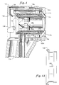
- Fig. 4 is a cross-sectional view of an alternate embodiment of the fuel injector shown in Fig. 2 having a separate passage for the injection of steam.
- Fig. 4a is a cross-sectional view of an alternate embodiment of the means for injecting steam shown in Fig. 4.
- Fig. 5 is an exploded view of the fuel injector shown in Fig. 4.
- Fig. 1 is a side elevation view of an axial flow rotary machine 10 of the industrial gas turbine engine type.
- the engine has an axis A.
- a compression section 12, a combustion section 14, and a turbine section 16 are disposed circumferentially about the axis A.
- An annular flowpath 18 for working medium gases extends circumferentially about the axis A and rearwardly through the sections of the engine.
- the compression section 12 includes a diffuser region 22 which is immediately upstream of the combustion section 14.
- Each combustionchamber is adapted by one or more openings 26 to receive pressurized gases in the form of air from the diffuser region of the compression section. These gases are relatively hot in comparison to ambient temperature but are relatively cool with respect to the products of combustion which are formed in the combustion chamber.
- a fuel injector as represented by the fuel injector 28, is disposed in an associated opening 26 in the combustion chamber 24 to pass the pressurized gases (air) from the compression section to the combustion chamber and to inject fuel into the air after the air is discharged into the discharge region of the injector.
- An igniter (not shown) extends into the combustion chamber to ignite the mixture of fuel and air as the air passes from the discharge region of the fuel injector.
- the gas turbine engine is provided with fluids such as a source of liquid fuel 32, a source of gaseous fuel 34 and a source of water 36.
- a heat exchanger 38 is provided to provide a source of steam from the source of water.
- the steam is a gaseous fluid.
- the heat exchanger may be regeneratively heated by the hot gases discharged from the gas turbine engine.
- An electronic fuel control 42 such as the fuel control Model Series DCS501 manufactured by the Woodward Governor Company, Fort Collins, Colorado, controls the flow of liquid fuel and water to the fuel injector and a flow of gaseous fuel as the source of steam for supplying fuel or steam to the fuel injector.
- a first conduit means 44 is in flow communication with the fuel injector and is adapted to be in flow communication with the source of gaseous fuel the source of steam for supplying fuel or steam to the fuel injector.
- a second conduit means 46 is in flow communication with the fuel injector and is in flow communication with the source of liquid fuel and the source of water for supplying liquid fuel, water or a mixture of liquid fuel and water to the fuel injector.
- Fig. 2 is an enlarged cross sectional view of the fuel injector 28 shown in Fig. 1.
- the fuel injector has an axis A f , an upstream end 48 and a downstream end 52.
- the fuel injector includes an inner air supply means 54 having a smaller diameter at the downstream end and a larger diameter at the upstream end.
- a first outer wall 56 extends axially over the downstream end of the inner air supply means.
- the first outer wall has an outer surface 55 at the downstream end which is conical in shape and inclined toward the axis of A f of the fuel injector.
- the first outer wall is spaced radially from the inner air supply means 54 leaving a passage 57 for liquid fuel therebetween.
- a casing 58 extends axially over the downstream end of the first outer wall and axially over the larger diameter portion of the upstream end of the inner air supply means 54.
- the casing has manifold sections 62 and a conical deflector section 64 which are integrally joined together to form a one-piece construction. Alternatively, these three sections might be formed as one piece.
- the inner air supply means 54 includes an inner wall 66 extending circumferentially about the axis A f of the fuel injector leaving an inner air chamber 68 inwardly of the wall.
- the inner air chamber has a length L c .
- the inner wall includes a heat shield 70 which extends circumferentially about the inner wall to bound the inner air chamber and to shield the inner wall from the pressurized gases discharged from the compressor which are relatively hot in comparison to the liquid fuel in the liquid fuel passage 57.
- the inner wall 66 has an upstream end 72 is open to receiving air from an upstream location, such as the diffuser region 22 of the compression section 12.
- the inner wall as a downstream end 74 for discharging air into the discharge region 75 of the fuel injector.
- the inner air supply means 54 includes a center body 76 which is solid and which is disposed entirely within the inner chamber 68.
- the center body extends axially in the inner chamber and has an axial length L cb .
- the center body 76 has an outer surface 78 which extends axially and which is spaced radially from the inner wall leaving a first annular passage 82 for air therebetween.
- the center body extends axially toward and into close proximity with the downstream end 74 of the inner wall 66.
- the center body has a downstream end surface 84 which extends radially to join the outer surface in blocking gases from entering the center body. Accordingingly, the center body does not have a concave surface at the downstream end which would permit gases to enter the center body.
- the downstream end surface 84 is spaced axially from the downstream end of the wall by a distance C a , leaving a gap therebetween to provide a region of sudden expansion Re within the inner chamber for the air downstream of the center body.
- the axial gap C a may range from approximately 2% to 4% of the length of the inner air chamber L c , but may, in some constructions be 10% of the length of the inner air chamber.
- the axial length L cb of the center body is greater than half the axial length of the inner wall L w or the inner chamber L c .
- the preferred range for the length of the center body is seven tenths to nine tenths of the length L c of the inner chamber (0.9 ⁇ L cb /L c ⁇ 0.7).
- the preferred range for the area of the center body at the region of sudden expansion R e is two tenths to six tenths of the area of the inner air chamber at that location (0.6 ⁇ A cb /A c ⁇
- a plurality of swirl vanes are disposed within the first passage at an axial location which is about midway between the upstream end 72 and the downstream end 74 of the inner wall.
- the swirl vanes extend between the heat shield 70 of the inner wall 66 and the center body 76 to support the center body.
- the swirl vanes provide means for imparting a tangential velocity to the air passing through the first passage 82.
- the swirl vanes may extend through the heat shield to the adjacent structure of the inner wall.
- the swirl vanes are at an angle which appoximately forth (40) degrees.
- the first outer wall 56 is spaced radially from the inner wall 66 leaving the second annular passage 57 for liquid fuel therebetween.
- the first outer wall is hollow having an internal gap G s along an axial portion of the first outer wall adjacent to the second annular passage.
- the second annular passage has a downstream end 88 for discharging liquid fuel into the discharge region of the fuel injector.
- An annular projection 92 from the inner wall 66 extends circumferentially between the inner wall and the first outer wall.
- a plurality of axially extending orifices 94 divide the liquid fuel passage into an upstream zone 96 and a downstream zone 98 and help meter the flow of fuel between the upstream zone and the downstream zone and into the discharge region 75.
- the casing 58 has a second outer wall 102 spaced radially from the first outer wall 56 leaving a third annular passage for air 104 therebetween.
- the third annular passage has an upstream end 106 which is open to receiving air from the upstream location which is the discharge region 22 of the compression section 12.
- the third passage has a downstream end 108 for discharging air into the discharge region.
- the second outer wall 102 has an inner surface 110 at the downstream end 108.
- the inner surface faces the outer surface 55 of the first outer wall.
- the surface is conical in shape and is inclined toward the axis of the injector A f .
- the third passage has annular inlet area A l and an annular exit area A e as measured in a direction generally perpendicular to the passage and facing in the upstream direction.
- the annular cross sectional area decreases from a value A i to a value A e which is less than or equal to one-half of A i .
- the third passage has a decreasing cross-sectional area adjacent at least one of said walls which forms an acceleration section 112 for accelerating the flow prior to entrance into the discharge region.
- Means for imparting tangential velocity to the air passing through the second annular passage are disposed in the third annular passage.
- the swirl vanes are adjacent to the downstream end of the nozzle.
- the swirl vanes are spaced axially from the acceleration section of the third passage in the upstream direction, leaving a mixing section 116 therebetween.
- the conical deflector section 64 of the casing includes a conical deflector 117 which is integrally joined to the casing.
- the conical deflector extends inwardly towards the axis A f of the injector to deflect the swirling air of the third annular passage 104 toward the liquid fuel discharged from the second annular passage 57.
- a fourth annular passage 118 is disposed in the casing for discharging a gas into the third passage.
- the fourth passage is in flow communication with the mixing section 116 of the third passage at an axial location downstream of the tangential velocity means 114 and upstream of the acceleration section 112.
- the fourth passage has a plurality circumferentially spaced orifices 122 which extend through the casing. The orifices are in flow communication with the mixing section 116 of the third annular passage.
- Fig. 3 is an enlarged view of a portion of the fuel injector shown in Fig. 2.
- Fig. 3 shows the third annular passage 104, the swirl means 114, the mixing section 116, and a portion of the acceleration section 112.
- the orifices 122 are sized to cause injection of the gas into the mixing region 116 with a component of velocity which extends in the radial direction.
- Each of said orifices is circular in cross-section and has a diameter d.
- Each orifice is in close proximity to the swirl means 114 and the acceleration section 112 such that the distance L t from the orifice to the swirl (tangential velocity) means 114 and the distance L a from the orifice to the acceleration section are each less than or equal to the diameter or axial length of the orifice.
- the orifice might be a slot having an axial length greater than its circumferential width.
- the first conduit means 44 is in flow communication with the fourth annular passage 118.
- the first conduit means is adapted to receive gaseous fuel from the source of gaseous fuel 34 and gaseous water (steam) from the source of steam 38. Under some operative conditions of the engine, it might be possible to flow only steam through the gaseous fuel passage.
- the second conduit means 46 extends across the third annular passage 104 for air to the second annular passage 57 for fuel.
- the second conduit means 46 is in the flow communication with the source of liquid fuel 32 and the source of water 36.
- the axial location of the second conduit means is adjacent to the upstream end 48 of the fuel injector to minimize the disruption of the circumferential flow of air in the air passage 104 prior to the air flow passing through the downstream swirl vanes 114.
- Fig. 4 is a cross sectional view of an alternate embodiment 28a of the fuel injector shown in Fig. 2. Because of the similarity between the fuel injectors, the same numerals are used for the embodiment shown in Fig. 4 as are used in connection with Fig. 2 with the addition of the subscript a. Thus, the fuel injector in Fig. 2 has the numeral 28 and the fuel injector in Fig. 4 has the numeral 28a.
- the fuel injector 28a includes means 124 for flowing gaseous fluid into the first annular passage 82 which is the inner means for forming an annular stream of air rotating about the axis A f of the fuel injector.
- the means 124 includes an annular passage 126 which extends circumferentially about the fuel injector.
- a plurality of circumferentially spaced local ducts 128 extend across the third annular passage for air 104a.
- Each duct 128 has an orifice 132 for discharging a gaseous fluid such as steam into the inner air chamber 68a.
- the means 124 is in flow communication with a source of steam through the conduit 134. This provides the capability of injecting an amount of steam into the inner cavity in addition to the steam in the fourth annular passage 118 for gaseous fluid. Under another operative condition the fourth annular passage might receive gaseous fuel.
- Fig. 4a is a cross-sectional view of a second means 136 for injecting steam into the fuel injector.
- the means 136 includes a plurality of orifices in flow communication with the passage 126 in the casing 58a for steam.
- the means 136 has orifices 138 which are sized under operative conditions to inject steam primarily into the third annular passageway for air 104a or into the first annular passage 82a for air or into both passages for air.
- working medium gases are flowed along the working medium flowpath 18.
- the gases are in the form of air when discharged from the compressor into the diffuser region 22.
- the air enters the open upstream end 48 of the fuel injector passing through the first annular passage 82 and the third annular passage 104 to form two swirling columns of air which are radially spaced one from the other.
- the columns of air are swirling in the same direction in the embodiment shown. In alternate embodiments, the columns of air may swirl in different directions.
- liquid fluid in the form of fuel or water or a mixture of fuel and water are flowed via the second annular passage 57 between these two columns.
- the heat shield 70 is disposed between the first annular passage and the second annular passage and the gap G s is in the first outer wall. These block the transfer of heat from the air in the first annular passage and the third annular passage to the liquid fuel and water in the second annular passage.
- the liquid fluid is directed toward the inner airstream by the conical deflector or filmer 142 at the downstream end of the first outer wall 56.
- the conical deflector 117 on the third outer wall deflects the outer air stream towards the fuel and/or water stream, causing a shearing action which atomizes the fluid and provides a good dispersion of the fluid in air. Combustion takes place downstream of this location.
- Gaseous fluid is added via the fourth annular passage.
- gaseous steam may be added via the fourth annular passage to the atomized liquid fuel.
- gaseous fuel may be the only fuel supplied outwardly of the inner swirling airstream. Under this condition, only water is flowed through the second annular passage. The water is dispersed by the co-rotating airstreams after the gaseous fuel is premixed with the outer airstream.
- the design of the nozzle is compact and provides for operation of the fuel injector with premixed air and gaseous fuel from the fourth passage and from the second passage water, or fuel, or a mixture of water and fuel.
- the fourth passage might be used to add steam which is premixed with the outer airstream.
- the air-stream mixture is then mixed with the atomized fuel, water, or mixtures of water and fuel, supplied via the second passage.
- a particular advantage of this construction is the addition of gas via the mixing section 116 which is in flow communication via the orifices 122 with the gaseous fuel or the gaseous steam.
- the mixing section 116 which is in flow communication via the orifices 122 with the gaseous fuel or the gaseous steam.
- Injection of fuel at this location takes advantage of the pressure drop across the swirl means 114 to avoid back-flow of the combustible mixture into the third annular passageway. Avoiding back-flow avoids the gaseous fuel having a higher residence time in this region of the fuel injector which might result in ignition of the combustible fuel and air mixture at this location with damage to the fuel injector.
- either fuel injector is easily assembled by integrally joining the manifold section 62 to the conical deflector section 64 to form the first casing module.
- the casing module is slidable with respect to the inner wall 66 and the first outer wall 56. Assembly is further enhanced by the modularity of the inner air supply means 54 which includes the inner wall 66 and its heat shield 70, and the center body 76 and swirl vanes 86 which may be fabricated as a unit.
- the swirl vanes 86 may engage the heat shield 70 or the inner wall 66. Should the vanes engage the heat shield 70, the contracting nature of the inner wall 66 will provide retention of the swirl vanes should the swirl vanes separate for any reason from the heat shield.
- the inner air supply means may be fabricated as one-piece construction and the casing and conical deflector assembled as another one-piece construction.
- the first outer wall 56 is slidable over the inner air supply means and the casing is slidable over the first outer wall to provide the assembled configuration.
- the first and second conduits are inserted through the casing to complete the construction.
- the third conduit and either the means 124 or 136 are added to the casing to supply steam.
Landscapes
- Engineering & Computer Science (AREA)
- Chemical & Material Sciences (AREA)
- Combustion & Propulsion (AREA)
- Mechanical Engineering (AREA)
- General Engineering & Computer Science (AREA)
- Fuel-Injection Apparatus (AREA)
Claims (24)
- Injecteur de carburant pour un moteur à turbine à gaz ayant des passages pour de l'air, pour un fluide liquide et pour un fluide gazeux, l'injecteur de carburant (28) s'étendant circonférentiellement autour d'un axe (Af) et ayant une région de décharge (75) à une extrémité avale de l'injecteur (28), qui comporte:caractérisé en ce que le moyen pour faire passer le fluide gazeux est formé pour faire passer le fluide gazeux dans l'un des courants d'air avant de mélanger le courant d'air et de fluide gazeux avec le fluide liquide ou l'autre courant d'air;un moyen pour former un premier courant d'air annulaire tournant autour de l'axe (Af) et pour décharger le courant vers la région de décharge (75), et pour diriger le courant dans une première direction;un moyen pour former un second courant d'air annulaire tournant autour de l'axe (Af) et pour décharger le courant vers la région de décharge (75), et pour diriger le courant dans une seconde direction vers le premier courant annulaire, le premier courant annulaire étant radialement espacé du second courant annulaire le long d'au moins une partie de son étendue axiale;un moyen pour faire passer le fluide liquide à travers l'injecteur (28) entre les deux courants rotatifs avant la décharge de l'injecteur (28) vers la région de décharge et pour décharger le fluide liquide entre les deux courants rotatifs vers la région de décharge (75); et,un moyen pour faire passer le fluide gazeux;dans lequel l'un des fluides est du carburant à l'état approprié et l'autre fluide est de l'eau à l'état approprié,ce mélange entre l'air et le fluide gazeux avant le mélange avec le fluide liquide résultant en un mélange plus uniforme pour la combustion.
- Injecteur de carburant selon la revendication 1, caractérisé en ce que le moyen pour faire passer le fluide gazeux est un moyen pour faire passer du carburant.
- Injecteur de carburant selon la revendication 1, caractérisé en ce que le moyen pour faire passer le fluide liquide est un moyen pour faire passer au moins en partie du carburant et le moyen pour faire passer le fluide gazeux est un moyen pour faire passer de l'eau à l'état de vapeur.
- Injecteur de carburant selon la revendication 3, caractérisé en ce que le moyen pour faire passer le fluide liquide est un moyen pour faire passer un mélange de carburant et d'eau.
- Injecteur de carburant selon la revendication 3, caractérisé en ce que le premier courant d'air annulaire se trouve radialement à l'intérieur du second courant d'air annulaire et en ce que le moyen pour faire passer du fluide gazeux dans l'un des courants d'air est un moyen pour faire passer de la vapeur et se trouve en communication avec le premier courant d'air (interne).
- Injecteur de carburant selon la revendication 5, caractérisé en ce que l'injecteur de carburant a une extrémité amont (48), une extrémité avale (52), une chambre d'air interne (68), une paroi interne (66) qui s'étend circonférentiellement pour limiter la chambre d'air interne (68), un corps central (76a) disposé à l'intérieur de la chambre d'air interne (68) et écarté radialement de la paroi interne (66) pour laisser un passage annulaire (82a) pour le premier courant d'air entr'eux, une paroi externe (102) écartée radialement de la paroi interne (66) laissant un second passage annulaire (104a) entr'elles pour le second courant d'air qui est délimité en partie par la paroi externe (102) et en ce que le moyen pour faire passer de la vapeur a un passage (126) de vapeur s'étendant circonférentiellement et délimité en partie par la paroi externe (102) et a une pluralité de conduits (128) espacés circonférentiellement autour de l'extrémité amont (48) de l'injecteur de carburant (28), qui sont en communication avec le passage annulaire (82a) pour le premier courant d'air et le passage de vapeur annulaire (126).
- Injecteur de carburant selon la revendication 3, caractérisé en ce que le premier courant d'air annulaire se trouve radialement à l'intérieur du second courant d'air annulaire et en ce que le moyen pour faire passer du fluide gazeux dans l'un des courants d'air est un moyen pour faire passer de la vapeur et est en communication avec le second courant d'air (externe).
- Injecteur de carburant selon la revendication 1, caractérisé en ce que le second courant d'air annulaire se trouve radialement à l'extérieur du premier courant d'air annulaire, en ce que l'injecteur de carburant (28) a en outre un passage annulaire (104; 104a) qui délimite le second courant d'air annulaire, ce passage (104, 104a) ayant une section de mélange (116, 116a) qui est en communication avec le fluide gazeux, et en ce que le passage annulaire (104; 104a) a un moyen de tourbillonnement (114; 114a) pour communiquer une composante de vitesse tangentielle à l'air se trouvant en amont de la section de mélange (116, 116a).
- Injecteur de carburant selon la revendication 8, caractérisé en ce que le moyen de tourbillonnement (114; 114a) a une pluralité d'aubes de tourbillonnement (114, 114a).
- Injecteur de carburant selon la revendication 8, caractérisé en ce que le passage (104; 104a) a une section d'accélération (112; 112a) en aval de la section de mélange (116; 116a), dont la surface est convergente et qui est inclinée vers l'axe (Af) de l'injecteur de carburant (28).
- Injecteur de carburant selon la revendication 10, caractérisé en ce que le passage annulaire (104; 104a) est délimité en partie par une paroi externe (102), et en ce qu'une pluralité d'orifices espacés circonférentiellement (122, 122a) placent la section de mélange (116; 116a) en communication avec le fluide gazeux.
- Injecteur de carburant selon la revendication 11, caractérisé en ce que les orifices (122; 122a) sont curvilignes en section transversale mesuré perpendiculairement à la direction de courant du fluide gazeux.
- Injecteur de carburant selon la revendication 12, caractérisé en ce que les orifices (122; 122a) sont circulaires en coupe transversale.
- Injecteur de carburant selon la revendication 11, caractérisé en ce que les orifices (122; 122a) sont des rainures dont la longueur axiale est plus grande que la largeur circonférentielle.
- Injecteur de carburant selon la revendication 11, caractérisé en ce que les moyens de tourbillonnement (114; 114a) et la section d'accélération (112; 122a) sont espacés axialement des orifices (122; 122a) d'une distance qui n'est pas plus grande que la longueur axiale de l'orifice.
- Injecteur de carburant selon la revendication 11, caractérisé en ce que orifices (122; 122a) sont en communication avec une source de vapeur.
- Injecteur de carburant selon la revendication 11, caractérisé en ce que les orifices (122; 122a) sont en communication avec une source de carburant.
- Injecteur de carburant selon la revendication 1, caractérisé par:une paroi interne (66) s'étendant circonférentiellement autour de l'axe (Af) laissant une chambre d'air interne (68) à l'intérieur de la paroi interne (66), cette chambre d'air interne (68) ayant une extrémité amont (72) qui est ouverte pour recevoir de l'air d'un endroit amont et une extrémité avale (74) pour décharger de l'air dans la région de décharge (75),un corps central (76) s'étendant axialement qui est disposé dans la chambre interne (68), ce corps central (76) ayant une surface externe (78) qui s'étend axialement et qui est écartée radialement de la paroi interne (66) laissant un premier passage annulaire (82) pour le premier courant d'air entr'eux, le corps central (76) ayant une surface d'extrémité avale (84) qui s'étend radialement pour rejoindre la surface externe (78) et pour empêcher au gaz d'entrer dans le corps central (76), la surface d'extrémité avale (84) étant écartée axialement de l'extrémité avale (74) de la paroi interne (66) laissant un écartement Ca entr'elles pour former une région d'expansion soudaine en aval du corps central (76) à l'intérieur de la chambre interne (68);un moyen (86) pour communiquer une vitesse tangentielle au premier courant d'air passant à travers le premier passage annulaire (82), qui est disposé dans le premier passage annulaire (82);une première paroi externe (56) écartée radialement de la paroi interne (66) laissant un second passage annulaire (57) pour le fluide liquide entr'elles, ce second passage annulaire (57) ayant une extrémité avale (88) pour décharger du fluide liquide dans la région de décharge (75), la première paroi externe (56) ayant une surface externe (55) à l'extrémité avale qui a une forme conique et qui est inclinée vers l'axe (Af) de l'injecteur (28);une enveloppe (58) ayant une seconde paroi externe (102) écartée radialement de la première paroi externe (56) laissant entr'elles un troisième passage annulaire (104) pour le second courant d'air, ce troisième passage annulaire (104) ayant une extrémité amont (106) qui est ouverte pour recevoir de l'air en provenance d'un endroit amont et une extrémité avale (108) pour décharger de l'air dans la région de décharge (75), la seconde paroi externe (102) ayant une surface interne (110) à son extrémité avale (108) qui fait face vers la surface externe (55) de la première paroi externe (56) et qui a une forme conique et est inclinée vers l'axe (Af) de l'injecteur (28), le troisième passage annulaire (104) ayant une surface en coupe transversale qui diminue, à proximité d'au moins l'une de ces parois (56, 102) en vue de former une section d'accélération (112) pour accélérer le courant avant l'entrée dans la région de décharge (75), la surface annulaire en coupe transversale diminuant d'une valeur Ai vers une valeur Ae qui est inférieure ou égale à la moitié de Ai;un moyen (114) pour communiquer une vitesse tangentielle au second courant d'air passant par le troisième passage annulaire (104), qui est disposé dans le troisième passage annulaire (104) en un endroit axial à proximité de l'endroit axial de l'extrémité avale (74) de la première paroi (66), et qui est espacé axialement de la section d'accélération (112) du troisième passage annulaire (104) dans la direction amont, laissant une section de mélange (116) entr'elles;un quatrième passage annulaire (118) disposé dans l'enveloppe (58) pour décharger le fluide gazeux dans le troisième passage annulaire (104), ce quatrième passage annulaire (118) étant en communication avec la section de mélange (116) du troisième passage annulaire (104) en un endroit axial en aval du moyen (114) pour communiquer une vitesse tangentielle et en amont de la section d'accélération (112), le quatrième passage annulaire (118) ayant une pluralité d'orifices (122) espacés circonférentiellement qui sont dimensionnés pour injecter le fluide gazeux dans la section de mélange (116) avec une composante de vitesse qui s'étend dans la direction radiale, chacun de ces orifices (122) étant circulaire en coupe transversale et ayant un diamètre d et se trouvant à proximité étroite du moyen (116) pour communiquer une vitesse tangentielle et de la section d'accélération (112) de sorte que la distance Lt des orifices (122) jusqu'au moyen (114) pour communiquer une vitesse tangentielle et la distance La des orifices (122) de la section d'accélération (112) soient inférieures ou égales au diamètre des orifices (122);un premier moyen de conduit (44) qui est communication avec le quatrième passage annulaire (118) et qui est conçu en vue d'être en communication avec au moins une source de fluide gazeux;un second moyen de conduit (46) s'étendant à travers le troisième passage annulaire (104) vers le second passage annulaire (57) pour le fluide liquide qui est en communication avec le second passage annulaire (57) et qui est conçu en vue d'être en communication avec une source de fluide liquide.
- Injecteur de carburant selon la revendication 18, caractérisé en ce que le quatrième passage (118) est en communication avec une source de fluide gazeux (38) et le second passage annulaire (57) est en communication avec une source d'eau (36).
- Injecteur de carburant selon la revendication 18, caractérisé en ce que le quatrième passage annulaire (118) est en communication avec une source de carburant gazeux (34) et le second passage annulaire (57) est en communication avec une source de carburant (32).
- Injecteur de carburant selon la revendication 18, caractérisé en ce que le quatrième passage annulaire (118) est en communication avec une source de vapeur (38) et le second passage annulaire (57) est en communication avec une source d'eau (36).
- Injecteur de carburant selon la revendication 18, caractérisé en ce que le quatrième passage annulaire (118) est en communication avec une source de vapeur (38) et le second passage annulaire (57) est en communication avec une source d'eau et de carburant (32, 36).
- Injecteur de carburant selon la revendication 18, caractérisé en ce que le quatrième passage annulaire (118) est en communication avec une source de vapeur (38) et le second passage annulaire (57) est en communication avec une source de carburant (32).
- Procédé de mise en action d'un injecteur de carburant pour un moteur de turbine à gaz ayant des passages pour de l'air, pour un fluide liquide et pour un fluide gazeux, l'injecteur de carburant (28) s'étendant circonférentiellement autour d'un axe (Af) et ayant une région de décharge (75) en une extrémité avale de l'injecteur (28), comportant les étapes de:caractérisé par l'étape de laisser passer le fluide gazeux dans l'un des courants d'air avant le mélange du courant d'air et du fluide gazeux avec le fluide liquide ou l'autre courant d'air, et dans lequel le mélange entre l'air et le fluide gazeux avant le mélange avec le fluide liquide résulte en un mélange plus uniforme pour la combustion.former un premier courant d'air annulaire tournant autour de l'axe (Af) et décharger le courant vers la région de décharge (75), et diriger le courant dans une première direction;former un second courant d'air annulaire tournant autour de l'axe (Af) et décharger le courant vers la région de décharge (75) et diriger le courant dans une seconde direction vers le premier courant annulaire, le premier courant annulaire étant radialement espacé du second courant annulaire le long d'au moins une partie de son étendue axiale;laisser passer le fluide liquide à travers l'injecteur (28) entre les deux courants rotatifs avant la décharge de l'injecteur vers la région de décharge (75) et décharger le fluide liquide entre les deux courants rotatifs vers la région de décharge; et,laisser passer le fluide gazeux à travers l'injecteur (28);dans lequel l'un des fluides est du carburant à l'état approprié et l'autre fluide est de l'eau à l'état approprié;
Applications Claiming Priority (3)
| Application Number | Priority Date | Filing Date | Title |
|---|---|---|---|
| US08/099,668 US5423173A (en) | 1993-07-29 | 1993-07-29 | Fuel injector and method of operating the fuel injector |
| PCT/US1994/007845 WO1995004244A1 (fr) | 1993-07-29 | 1994-07-13 | Injecteur de carburant et son procede d'utilisation |
| US99668 | 1998-06-18 |
Publications (2)
| Publication Number | Publication Date |
|---|---|
| EP0710347A1 EP0710347A1 (fr) | 1996-05-08 |
| EP0710347B1 true EP0710347B1 (fr) | 1999-06-16 |
Family
ID=22276064
Family Applications (1)
| Application Number | Title | Priority Date | Filing Date |
|---|---|---|---|
| EP94923451A Expired - Lifetime EP0710347B1 (fr) | 1993-07-29 | 1994-07-13 | Injecteur de carburant et son procede d'utilisation |
Country Status (5)
| Country | Link |
|---|---|
| US (1) | US5423173A (fr) |
| EP (1) | EP0710347B1 (fr) |
| JP (1) | JP3782822B2 (fr) |
| DE (1) | DE69419156T2 (fr) |
| WO (1) | WO1995004244A1 (fr) |
Families Citing this family (45)
| Publication number | Priority date | Publication date | Assignee | Title |
|---|---|---|---|---|
| GB9321505D0 (en) * | 1993-10-19 | 1993-12-08 | Europ Gas Turbines Ltd | Fuel injector |
| EP0851990B1 (fr) * | 1995-09-22 | 2001-12-05 | Siemens Aktiengesellschaft | Bruleur, en particulier pour turbine a gaz |
| US5784875A (en) * | 1995-11-27 | 1998-07-28 | Innovative Control Systems, Inc. | Water injection into a gas turbine using purge air |
| US6474071B1 (en) * | 2000-09-29 | 2002-11-05 | General Electric Company | Multiple injector combustor |
| US6381964B1 (en) * | 2000-09-29 | 2002-05-07 | General Electric Company | Multiple annular combustion chamber swirler having atomizing pilot |
| FR2824625B1 (fr) * | 2001-05-10 | 2003-08-15 | Inst Francais Du Petrole | Dispositif et procede d'injection d'un combustible liquide dans un flux d'air pour une chambre de combustion |
| US6543235B1 (en) | 2001-08-08 | 2003-04-08 | Cfd Research Corporation | Single-circuit fuel injector for gas turbine combustors |
| US6986255B2 (en) * | 2002-10-24 | 2006-01-17 | Rolls-Royce Plc | Piloted airblast lean direct fuel injector with modified air splitter |
| US6921034B2 (en) | 2002-12-12 | 2005-07-26 | General Electric Company | Fuel nozzle assembly |
| US7174717B2 (en) * | 2003-12-24 | 2007-02-13 | Pratt & Whitney Canada Corp. | Helical channel fuel distributor and method |
| US20060156733A1 (en) | 2005-01-14 | 2006-07-20 | Pratt & Whitney Canada Corp. | Integral heater for fuel conveying member |
| US7565807B2 (en) | 2005-01-18 | 2009-07-28 | Pratt & Whitney Canada Corp. | Heat shield for a fuel manifold and method |
| US7533531B2 (en) * | 2005-04-01 | 2009-05-19 | Pratt & Whitney Canada Corp. | Internal fuel manifold with airblast nozzles |
| DE102005024608B4 (de) * | 2005-05-25 | 2009-05-07 | Astrium Gmbh | Einspritzvorrichtung für Brennkammern von Flüssigkeitsraketentriebwerken |
| US7540154B2 (en) * | 2005-08-11 | 2009-06-02 | Mitsubishi Heavy Industries, Ltd. | Gas turbine combustor |
| US8096130B2 (en) | 2006-07-20 | 2012-01-17 | Pratt & Whitney Canada Corp. | Fuel conveying member for a gas turbine engine |
| US8353166B2 (en) | 2006-08-18 | 2013-01-15 | Pratt & Whitney Canada Corp. | Gas turbine combustor and fuel manifold mounting arrangement |
| US7765808B2 (en) | 2006-08-22 | 2010-08-03 | Pratt & Whitney Canada Corp. | Optimized internal manifold heat shield attachment |
| US8033113B2 (en) | 2006-08-31 | 2011-10-11 | Pratt & Whitney Canada Corp. | Fuel injection system for a gas turbine engine |
| US8166763B2 (en) * | 2006-09-14 | 2012-05-01 | Solar Turbines Inc. | Gas turbine fuel injector with a removable pilot assembly |
| US7703289B2 (en) | 2006-09-18 | 2010-04-27 | Pratt & Whitney Canada Corp. | Internal fuel manifold having temperature reduction feature |
| US7775047B2 (en) | 2006-09-22 | 2010-08-17 | Pratt & Whitney Canada Corp. | Heat shield with stress relieving feature |
| US7926286B2 (en) | 2006-09-26 | 2011-04-19 | Pratt & Whitney Canada Corp. | Heat shield for a fuel manifold |
| US8572976B2 (en) | 2006-10-04 | 2013-11-05 | Pratt & Whitney Canada Corp. | Reduced stress internal manifold heat shield attachment |
| US7716933B2 (en) | 2006-10-04 | 2010-05-18 | Pratt & Whitney Canada Corp. | Multi-channel fuel manifold |
| US7856825B2 (en) | 2007-05-16 | 2010-12-28 | Pratt & Whitney Canada Corp. | Redundant mounting system for an internal fuel manifold |
| US8146365B2 (en) | 2007-06-14 | 2012-04-03 | Pratt & Whitney Canada Corp. | Fuel nozzle providing shaped fuel spray |
| US7712313B2 (en) * | 2007-08-22 | 2010-05-11 | Pratt & Whitney Canada Corp. | Fuel nozzle for a gas turbine engine |
| US8286433B2 (en) * | 2007-10-26 | 2012-10-16 | Solar Turbines Inc. | Gas turbine fuel injector with removable pilot liquid tube |
| EP2236934A1 (fr) * | 2009-03-18 | 2010-10-06 | Siemens Aktiengesellschaft | Agencement de brûleur |
| US20110314831A1 (en) * | 2010-06-23 | 2011-12-29 | Abou-Jaoude Khalil F | Secondary water injection for diffusion combustion systems |
| US8919132B2 (en) | 2011-05-18 | 2014-12-30 | Solar Turbines Inc. | Method of operating a gas turbine engine |
| US8893500B2 (en) | 2011-05-18 | 2014-11-25 | Solar Turbines Inc. | Lean direct fuel injector |
| US9133767B2 (en) * | 2011-08-02 | 2015-09-15 | Siemens Energy, Inc | Fuel injecting assembly for gas turbine engine including cooling gap between supply structures |
| US9182124B2 (en) | 2011-12-15 | 2015-11-10 | Solar Turbines Incorporated | Gas turbine and fuel injector for the same |
| KR102005545B1 (ko) * | 2013-08-12 | 2019-07-30 | 한화에어로스페이스 주식회사 | 선회기 |
| WO2015069354A2 (fr) * | 2013-08-30 | 2015-05-14 | United Technologies Corporation | Double gicleur de combustible avec atomisation par filmage liquide pour turbine à gaz |
| US9556795B2 (en) * | 2013-09-06 | 2017-01-31 | Delavan Inc | Integrated heat shield |
| US10731861B2 (en) | 2013-11-18 | 2020-08-04 | Raytheon Technologies Corporation | Dual fuel nozzle with concentric fuel passages for a gas turbine engine |
| JP6410924B2 (ja) | 2014-08-14 | 2018-10-24 | シーメンス アクチエンゲゼルシヤフトSiemens Aktiengesellschaft | デュアルオリフィス噴霧器を備える多機能燃料ノズル |
| JP6400181B2 (ja) | 2014-08-14 | 2018-10-03 | シーメンス アクチエンゲゼルシヤフトSiemens Aktiengesellschaft | 噴霧器配列を備える多機能燃料ノズル |
| CN107076420B (zh) | 2014-08-14 | 2019-12-10 | 西门子公司 | 具有隔热罩的多功能燃料喷嘴 |
| JP6722491B2 (ja) * | 2016-04-01 | 2020-07-15 | 川崎重工業株式会社 | ガスタービンの燃焼器 |
| EP3517759A1 (fr) * | 2018-01-25 | 2019-07-31 | Siemens Aktiengesellschaft | Installation de turbine à gaz et procédé de fonctionnement d'une installation de turbine à gaz |
| US11920792B1 (en) * | 2023-03-13 | 2024-03-05 | Rtx Corporation | Cooling turbine engine fuel-air mixer with steam |
Family Cites Families (11)
| Publication number | Priority date | Publication date | Assignee | Title |
|---|---|---|---|---|
| US3684186A (en) * | 1970-06-26 | 1972-08-15 | Ex Cell O Corp | Aerating fuel nozzle |
| US3917173A (en) * | 1972-04-21 | 1975-11-04 | Stal Laval Turbin Ab | Atomizing apparatus for finely distributing a liquid in an air stream |
| GB2021254B (en) * | 1978-04-18 | 1982-10-27 | Lucas Industries Ltd | Fuel injector |
| US4327547A (en) * | 1978-11-23 | 1982-05-04 | Rolls-Royce Limited | Fuel injectors |
| GB2055186B (en) * | 1979-08-01 | 1983-05-25 | Rolls Royce | Gas turbine engine dual fuel injector |
| US4425755A (en) * | 1980-09-16 | 1984-01-17 | Rolls-Royce Limited | Gas turbine dual fuel burners |
| US4600151A (en) * | 1982-11-23 | 1986-07-15 | Ex-Cell-O Corporation | Fuel injector assembly with water or auxiliary fuel capability |
| GB2219070B (en) * | 1988-05-27 | 1992-03-25 | Rolls Royce Plc | Fuel injector |
| US4938417A (en) * | 1989-04-12 | 1990-07-03 | Fuel Systems Textron Inc. | Airblast fuel injector with tubular metering valve |
| US4977740A (en) * | 1989-06-07 | 1990-12-18 | United Technologies Corporation | Dual fuel injector |
| US5218824A (en) * | 1992-06-25 | 1993-06-15 | Solar Turbines Incorporated | Low emission combustion nozzle for use with a gas turbine engine |
-
1993
- 1993-07-29 US US08/099,668 patent/US5423173A/en not_active Expired - Lifetime
-
1994
- 1994-07-13 DE DE69419156T patent/DE69419156T2/de not_active Expired - Lifetime
- 1994-07-13 WO PCT/US1994/007845 patent/WO1995004244A1/fr active IP Right Grant
- 1994-07-13 EP EP94923451A patent/EP0710347B1/fr not_active Expired - Lifetime
- 1994-07-13 JP JP50583995A patent/JP3782822B2/ja not_active Expired - Lifetime
Also Published As
| Publication number | Publication date |
|---|---|
| JP3782822B2 (ja) | 2006-06-07 |
| JPH09501486A (ja) | 1997-02-10 |
| EP0710347A1 (fr) | 1996-05-08 |
| DE69419156D1 (de) | 1999-07-22 |
| WO1995004244A1 (fr) | 1995-02-09 |
| US5423173A (en) | 1995-06-13 |
| DE69419156T2 (de) | 2000-02-03 |
Similar Documents
| Publication | Publication Date | Title |
|---|---|---|
| EP0710347B1 (fr) | Injecteur de carburant et son procede d'utilisation | |
| US4977740A (en) | Dual fuel injector | |
| US5628192A (en) | Gas turbine engine combustion chamber | |
| US5490380A (en) | Method for performing combustion | |
| JP4800523B2 (ja) | エンジン排気エミッション減少のための燃料ノズル組立体 | |
| US5319935A (en) | Staged gas turbine combustion chamber with counter swirling arrays of radial vanes having interjacent fuel injection | |
| EP1934530B1 (fr) | Procédé de fonctionnement d'un moteur de turbine | |
| US6286298B1 (en) | Apparatus and method for rich-quench-lean (RQL) concept in a gas turbine engine combustor having trapped vortex cavity | |
| JP4658471B2 (ja) | ガスタービンエンジンの燃焼器エミッションを減少させる方法及び装置 | |
| US7703288B2 (en) | Fuel nozzle having swirler-integrated radial fuel jet | |
| EP0700499B1 (fr) | Chambre de combustion de moteur a turbine a gaz | |
| US7966821B2 (en) | Reduced exhaust emissions gas turbine engine combustor | |
| US5303554A (en) | Low NOx injector with central air swirling and angled fuel inlets | |
| US6327860B1 (en) | Fuel injector for low emissions premixing gas turbine combustor | |
| US20040011021A1 (en) | Gas-turbine engine combustor | |
| EP0548143B1 (fr) | Turbine à gaz avec un injecteur de carburant gazeux et injecteur pour une telle turbine | |
| KR100254274B1 (ko) | 가스터빈의 연소기 | |
| US11906165B2 (en) | Gas turbine nozzle having an inner air swirler passage and plural exterior fuel passages | |
| US5426933A (en) | Dual feed injection nozzle with water injection | |
| US6718769B2 (en) | Gas-turbine engine combustor having venturi mixers for premixed and diffusive combustion | |
| US20240183536A1 (en) | Turbine engine with fuel nozzle assembly | |
| EP4202302A1 (fr) | Buse de combustible et tourbillonneur |
Legal Events
| Date | Code | Title | Description |
|---|---|---|---|
| PUAI | Public reference made under article 153(3) epc to a published international application that has entered the european phase |
Free format text: ORIGINAL CODE: 0009012 |
|
| 17P | Request for examination filed |
Effective date: 19960222 |
|
| AK | Designated contracting states |
Kind code of ref document: A1 Designated state(s): CH DE FR GB LI |
|
| 17Q | First examination report despatched |
Effective date: 19971020 |
|
| GRAG | Despatch of communication of intention to grant |
Free format text: ORIGINAL CODE: EPIDOS AGRA |
|
| GRAG | Despatch of communication of intention to grant |
Free format text: ORIGINAL CODE: EPIDOS AGRA |
|
| GRAH | Despatch of communication of intention to grant a patent |
Free format text: ORIGINAL CODE: EPIDOS IGRA |
|
| GRAH | Despatch of communication of intention to grant a patent |
Free format text: ORIGINAL CODE: EPIDOS IGRA |
|
| GRAA | (expected) grant |
Free format text: ORIGINAL CODE: 0009210 |
|
| AK | Designated contracting states |
Kind code of ref document: B1 Designated state(s): CH DE FR GB LI |
|
| REG | Reference to a national code |
Ref country code: CH Ref legal event code: EP |
|
| REF | Corresponds to: |
Ref document number: 69419156 Country of ref document: DE Date of ref document: 19990722 |
|
| ET | Fr: translation filed | ||
| PLBE | No opposition filed within time limit |
Free format text: ORIGINAL CODE: 0009261 |
|
| STAA | Information on the status of an ep patent application or granted ep patent |
Free format text: STATUS: NO OPPOSITION FILED WITHIN TIME LIMIT |
|
| 26N | No opposition filed | ||
| REG | Reference to a national code |
Ref country code: GB Ref legal event code: IF02 |
|
| PGFP | Annual fee paid to national office [announced via postgrant information from national office to epo] |
Ref country code: FR Payment date: 20110727 Year of fee payment: 18 |
|
| REG | Reference to a national code |
Ref country code: FR Ref legal event code: ST Effective date: 20130329 |
|
| PG25 | Lapsed in a contracting state [announced via postgrant information from national office to epo] |
Ref country code: FR Free format text: LAPSE BECAUSE OF NON-PAYMENT OF DUE FEES Effective date: 20120731 |
|
| PGFP | Annual fee paid to national office [announced via postgrant information from national office to epo] |
Ref country code: DE Payment date: 20130711 Year of fee payment: 20 Ref country code: CH Payment date: 20130712 Year of fee payment: 20 |
|
| PGFP | Annual fee paid to national office [announced via postgrant information from national office to epo] |
Ref country code: GB Payment date: 20130710 Year of fee payment: 20 |
|
| REG | Reference to a national code |
Ref country code: DE Ref legal event code: R071 Ref document number: 69419156 Country of ref document: DE Ref country code: CH Ref legal event code: PL |
|
| REG | Reference to a national code |
Ref country code: GB Ref legal event code: PE20 Expiry date: 20140712 |
|
| PG25 | Lapsed in a contracting state [announced via postgrant information from national office to epo] |
Ref country code: DE Free format text: LAPSE BECAUSE OF EXPIRATION OF PROTECTION Effective date: 20140715 |
|
| PG25 | Lapsed in a contracting state [announced via postgrant information from national office to epo] |
Ref country code: GB Free format text: LAPSE BECAUSE OF EXPIRATION OF PROTECTION Effective date: 20140712 |