EP0710032A2 - Verfahren und Vorrichtung zur Bewegungsschätzung in einem Bildsignal - Google Patents
Verfahren und Vorrichtung zur Bewegungsschätzung in einem Bildsignal Download PDFInfo
- Publication number
- EP0710032A2 EP0710032A2 EP95307709A EP95307709A EP0710032A2 EP 0710032 A2 EP0710032 A2 EP 0710032A2 EP 95307709 A EP95307709 A EP 95307709A EP 95307709 A EP95307709 A EP 95307709A EP 0710032 A2 EP0710032 A2 EP 0710032A2
- Authority
- EP
- European Patent Office
- Prior art keywords
- motion
- signal
- estimator
- motion estimator
- pattern
- Prior art date
- Legal status (The legal status is an assumption and is not a legal conclusion. Google has not performed a legal analysis and makes no representation as to the accuracy of the status listed.)
- Withdrawn
Links
Images


Classifications
-
- H—ELECTRICITY
- H04—ELECTRIC COMMUNICATION TECHNIQUE
- H04N—PICTORIAL COMMUNICATION, e.g. TELEVISION
- H04N5/00—Details of television systems
- H04N5/14—Picture signal circuitry for video frequency region
- H04N5/144—Movement detection
- H04N5/145—Movement estimation
-
- G—PHYSICS
- G06—COMPUTING; CALCULATING OR COUNTING
- G06T—IMAGE DATA PROCESSING OR GENERATION, IN GENERAL
- G06T7/00—Image analysis
- G06T7/20—Analysis of motion
- G06T7/207—Analysis of motion for motion estimation over a hierarchy of resolutions
-
- G—PHYSICS
- G06—COMPUTING; CALCULATING OR COUNTING
- G06T—IMAGE DATA PROCESSING OR GENERATION, IN GENERAL
- G06T7/00—Image analysis
- G06T7/20—Analysis of motion
- G06T7/223—Analysis of motion using block-matching
- G06T7/238—Analysis of motion using block-matching using non-full search, e.g. three-step search
-
- H—ELECTRICITY
- H04—ELECTRIC COMMUNICATION TECHNIQUE
- H04N—PICTORIAL COMMUNICATION, e.g. TELEVISION
- H04N19/00—Methods or arrangements for coding, decoding, compressing or decompressing digital video signals
- H04N19/50—Methods or arrangements for coding, decoding, compressing or decompressing digital video signals using predictive coding
- H04N19/503—Methods or arrangements for coding, decoding, compressing or decompressing digital video signals using predictive coding involving temporal prediction
- H04N19/51—Motion estimation or motion compensation
- H04N19/53—Multi-resolution motion estimation; Hierarchical motion estimation
-
- G—PHYSICS
- G06—COMPUTING; CALCULATING OR COUNTING
- G06T—IMAGE DATA PROCESSING OR GENERATION, IN GENERAL
- G06T2207/00—Indexing scheme for image analysis or image enhancement
- G06T2207/10—Image acquisition modality
- G06T2207/10016—Video; Image sequence
Definitions
- the present invention relates to an improved method of and device for measuring motion in a video signal.
- Such motion is usually expressed as a motion vector field in which the motion of each element of the picture is expressed as a motion vector conventionally resolved along two orthogonal axes, e.g. horizontal and vertical motion axes.
- Prior art techniques for measurement of motion in a video signal includes block matching, pixel recursive methods (Gradient methods) and phase correlation. Since the present invention provides an improvement of block matching, a brief discussion of block matching follows herein under. Details of the phase correlation method can be found in U.K. Patent No. GB2188510A, and details of the pixel recursive method can be found in the Article by Shimano et al, entitled 'Movement Compensated Standards Converter Using Motion Vectors' in the Proceedings of The Society of Motion Picture and Television Engineers, 1989.
- a block matching system the picture is divided into a series of rectangular sections (blocks).
- the motion of the video within each block is measured by comparing each block with a selection of similar sized blocks derived from an adjacent (proceeding or preceding) field of the video signal. This is illustrated in Figure 1.
- Matching is measured by evaluating the difference between the magnitude of each pixel of the current field P o with the correspondingly placed pixel P a within the block of the adjacent field.
- a more reliable indication of the proximity of a correct match may be achieved if the input video signal is spatially filtered, to reduce the high horizontal and vertical frequency components of the signal, before the block-match estimations are carried out. If however a hierarchical search technique is used, then the high frequency components of the signal are required to give adequate resolution when small block displacements are tested around an approximately correct position. In the system described, the amount of detail present in the video signal is progressively increased in successive searches.
- Another source of error encountered in block matching motion estimators is introduced when the video signal represents a scene in which objects are moving at different speeds, and hence may obscure one another. For example, if a measurement block in one field contains an area of a picture background and if in the next field a small area of the corresponding picture block is obscured by an object moving in front, then a significant error may occur in the matching of the corresponding blocks.
- a technique is described in which the significance of a difference between corresponding pixels of two blocks which are being compared is scaled according to the position of the pixel in the block pattern. This technique reduces the effect of discontinuities in motion at the extremes of the block.
- the invention described in this patent introduces novel techniques of weighted-sample area matching, effectively giving soft boundaries to the picture areas used to assess motion within a picture, together with a technique of adjusting the picture resolution between successive stages of motion measurement.
- novel techniques of weighted-sample area matching effectively giving soft boundaries to the picture areas used to assess motion within a picture
- a technique of adjusting the picture resolution between successive stages of motion measurement reduces many of the limitations of previous techniques.
- a device for estimating motion in an electronic visual signal comprising:
- a motion estimator for estimating motion in an electronic visual signal, comprising:
- FIG. 2 shows a block diagram one embodiment of the present invention.
- the description refers to video signal that is meant to include all electronic forms of visual data.
- An input video signal 20 is applied to a video delay 1 which has a delay of one television frame or one television field. If the signal has an interlaced format, such as a 625-line or 525-line television signal, then a de-interlacing circuit is included in the field delay as shown in figure 8.
- the input signal 20 is also applied to a two dimensional low-pass spatial filter 3, the output of which 21, is connected to a further low-pass spatial filter 4.
- the output of which 22 is connected to a further low-pass spatial filter 5 which in turn provides an output 23. Filtered outputs 21, 22 and 23 thus represent increasingly filtered versions of the input video 20.
- a similar cascaded series of filters 6, 7 and 8, connected to the output of video delay 1 are used to provide increasingly filtered versions 25, 26 and 27 of the delayed video signal 24.
- the output 23 of low-pass filter 5, representing the most filtered version of the input signal, and the output 27 of low-pass filter 8, representing the most filtered version of the delayed video signal, are connected to a first motion estimator 11.
- This first motion estimator 11 is arranged to measure the motion within the picture at a number of points in the picture. These measurement points may be defined by a first motion measurement array.
- a motion measurement array is shown diagramatically in Figure 9A, this shows an orthogonal pattern of points within a picture at which a motion measurement is made. In practice, a larger number of points may be preferred.
- an array of 30 points horizontally across the picture by 24 points vertically could be used or a block of 24 pixels across and 12 pixels vertically could be used in this stage of estimation.
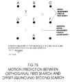
- An alternative arrangement of a motion measurement array, in which the motion measurement points are offset in a quincunx formation is shown in Figure 9B: again more points may be preferred in a practical system as explained for an orthogonal array.
- the output from the first motion estimator is thus a series of motion measurements at points spatially defined by the first motion measurement array. This represents a low-accuracy vector field sampled at low spatial resolution.
- the output 28 of the first motion estimator is connected to a spatial interpolator 12.
- the function of the interpolator is to provide an output 29 which predicts the motion at intermediate points in the picture. These points may be defined by a second motion measurement array, typically having more horizontal and more vertical sampling points than the first motion measurement array.
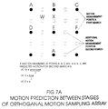
- the process of increasing the number of sample points to provide an estimate of motion at points in a higher resolution, second motion measurement array is shown in Figures 7A and 7B.
- the interpolator 12 may provide a number of motion predictions for each of the intermediate points.
- the motion at intermediate points may be estimated by averaging the surrounding motion measurements defined at points on the first motion measurement array, or by providing a number of estimates each based on the motion measured at points on the first motion measurement array.
- Interpolated signal 29 is connected to a second motion estimator 13 where it is used to provide predicted values of the motion at the spatial sample points defined by the second motion measurement array
- Filtered versions of the input signal 20, derived from low-pass filters 4 and 7 respectively, are delayed by delay circuits 9 to provide outputs 26 and are connected to the second motion estimator 13.
- the delay of circuits 9 are arranged to compensate for the cascaded insertion delay of filters 5 and 8 and the first search estimator 11 and interpolator 12.
- the second motion estimator is thus fed with versions of the input signal and the delayed input signal which have been subjected to less spatial filtering and hence have a higher spatial resolution than signals 23 and 27 fed to the first motion estimator.
- Predicted values of the motion at picture points defined by the second motion measurement array are also provided from the interpolator 12.
- the function of the second motion estimator is to provide a series of motion measurements at points in the picture defined by the second motion measurement array.
- An output 30 of the second motion estimator consists of a series of motion measurements corresponding to a vector field which has increased accuracy and is sampled at an increased spatial resolution.
- the second motion estimator may act on a block of 12 by 6 pixels. Moreover, the motion measurements centre upon the most likely motion as determined by the first motion estimator.
- the output 30 of second motion estimator 13 is connected to a further spatial interpolator 14 which provides an output 31 with further increased spatial sampling resolution at picture points corresponding to a third motion measurement array. This output forms a motion prediction for a third motion estimator 15.
- Versions of the input signal 20 from low pass filters 3 and 6 respectively, and delayed via delays 10 to provide signal 25 provide inputs to the third motion estimator 15.
- Delays 10 provide compensation for the timing difference between signals 21, 25 and the prediction signal 31.
- the function of the third motion estimator is similar to that previously described except that it measures motion at points in the picture defined by the third motion measurement array.
- the output of the third motion estimator 15 thus provides an output 32 which consists of a motion vector field with further enhanced accuracy and resolution. This output 32 may be used directly or connected to a further interpolator 16 to provide an output 33 with further increased spatial sampling resolution.
- FIG. 3 A block diagram of a particularly suitable motion estimator for use in this arrangement is shown in Figure 3.
- a first video input signal is connected to a first random access memory 40 and a second video signal corresponding to the first video signal delayed by one television field is connected to a second random access memory 41.
- Addresses to both first and second random access memories are provided by a search address controller 49.
- the search address controller allocates both write addresses, to define where each sample of the video signal is written into the memories, and read addresses, such that a pattern of picture elements can be read from the memories in sequential order.
- the outputs from memories 40 and 41 are connected to a subtractor circuit 42 which provides an output signal corresponding to the difference between the outputs from the two memories.
- the polarity of this difference is suppressed by a modulus circuit 43 connected to the output of the subtractor.
- the output of the modulus circuit is connected to a multiplier 44 which multiplies each pixel of the difference signal from modulus circuit 43 by a weighting factor 51.
- the weighting factors are derived from a search aperture store 50 which is controlled by the search address controller 49. For each address within the pattern of selected picture elements provided to the video memories 40 and 41, the store address controller can select a different weighting factor 51 from search aperture store 50.
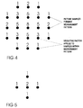
- Figure 4 shows an example of the spatial pattern of samples which can be selected from the memories 40, 41 together with an example of the weighting factor applied to each sample from the search aperture store 50.
- Figure 5 shows a smaller pattern of samples which could be used.
- the purpose of the weighting factors is to increase the significance of samples from near the centre of the search pattern and correspondingly reduce the significance of samples further from the centre of the search pattern.
- the output of the multiplier 44 is connected to accumulator circuit 45 which is arranged to add together all the weighted difference values derived from the pixels within the search pattern to provide a total difference signal for each pattern of pixels read from memories 40, 41. This total difference may be stored in the search result store 46.
- a pattern of samples of the current video field is addressed in random access memory 40 and simultaneously a similar pattern of samples corresponding to the previous video field is addressed in random access memory 41.
- the values derived for each picture element in the pattern from the two memories 40, 41 are subtracted and the modulus of the difference multiplied by a weighting coefficient is then added in accumulator 45.
- the modulus of the difference between each corresponding picture element in the pattern has been accumulated the final sum is transferred to search memory store 46.
- the position of the search pattern mapped into one of the memories is then moved horizontally, vertically or diagonally to a neighbouring position and the sum of the weighted picture element differences evaluated as before, and the result again transferred to the search result store.
- This process is repeated a number of times: each occasion with a different spatial offset of the pattern of samples addressed in the video memories 40, 41.
- the magnitude and direction of the spatial offset of the pattern between the memories 40, 41 is stored in the search address store 47 and the corresponding accumulated difference value stored in search result store 46.
- the results stored in the search result store are evaluated by a best match logic 48 to find the minimum value held.
- the minimum value has been found, the corresponding address in the search address store 47 is found.
- the value read from this store contains the magnitude and direction of the spatial address offset value which, applied to the video memories 40, 41, gave the best match of the picture elements contained in patterns accessed in memories 40, 41.
- This spatial offset provides the best estimate of the motion in the picture at a point centred on the centre of the pattern of picture elements read from memories 40, 41.
- the horizontal and vertical components of the address offset at which a best match is found then give a direct measurement of motion in terms of pixels moved horizontally and lines moved vertically per field.
- one or more predictions of probable motion can be fed to the search address controller. Searches for a best match of measurement pattern are then made at points in the picture offset by a displacement corresponding to the predicted motion over one field, and then at points surrounding this initial displacement. This process can then be repeated for several different possible predictions. The final best estimate of the motion of the point at the centre of the measurement pattern is given by the total address displacement at which a best match is found.
- the addresses to either video store 40 or delayed video store 41 can be offset from an original starting position for each search.
- the point at which the motion is measured is usually taken as the centre of the pattern in the store in which the pattern remains fixed during the search for a best match.
- An alternative mode of operation is for the addresses in both the video store 40 and delayed video store 41 to be both spatially offset from an original reference position by address shifts in offset directions. If the spatial offset of the addresses in the two stores 40, 41 are equal in magnitude and opposite in direction, this provides a best estimate of the motion in the picture that would have occurred at a time mid-way between the origination of the first video signal and the delayed video signal.
- the magnitude of the spatial address offset applied to the two video memories may be adjusted as follows:
- V is the total offset value which is stored in the search address store 47.
- the point in the picture at which motion is being measured remains the reference picture point about which the two store address patterns are being moved.
- Such measurement of motion based on an instant in between television fields can be critical if the motion measurement is made for the purpose of constructing accurate images at times in between the input television fields.
- Typical examples of this type of processing are television standards conversion and slow- motion processing.
- the method of motion measurement described so far assesses the motion occurring at one point in the picture.
- points can be built up.
- This array of results is fed sequentially from the best match logic 48 into a motion vector store 52.
- the output from the store can be read out to provide predictions for refinement in a further stage of motion estimation, or by repeating the motion estimation process over the whole field and an array of motion measurements can be built up to represent a complete sampled motion vector field.
- the array of points chosen to make motion measurements within the field can be such that the patterns of picture elements read from the video memories are either spatially adjacent in position at successive measurement points as shown in Figure 6A, or preferably, that the patterns of picture elements selected for measurement of motion at one point overlap the pattern of points selected for measurement of motion at other points in the array as shown in Figures 6B or 6C.
- Figure 2 shows an arrangement of successive motion estimators each giving a motion prediction to the next stage of motion estimation with later stages working at a higher resolution than the previous estimator.
- the first motion estimator 11 of Figure 2 provides a vector field, sampled on a relatively widely spaced array of motion sample points, which is used as a basis of predictions for the motion to be redefined at a higher accuracy on a more closely spaced array of picture points in the second motion estimator.
- the vector field derived from the first estimator must be spatially interpolated to provide additional sample points.
- a weighted sum of the surrounding picture points is taken to provide a prediction of the motion at intermediate points.
- Simple examples of the weighting functions that could be used are shown in Figure 7. Alternatively multiple predictions can be made from the values of motion measured at surrounding points.
- a further enhancement of the motion measurement system is the addition of temporal motion prediction.
- the results of motion measurement from all of the motion estimator stages 11,13,15 of Figure 2 may be connected to a measurement store.
- a weighted sum of the motion measurements made by the motion estimator stages may be read from this store and used to form a prediction of the motion in the picture one field later.
- This temporal prediction may be used in combination with the spatial prediction from earlier motion estimators as previously described.
- the cascade can also be vertical. That is to say, a signal and comparison signal are each applied to a plurality of filters and their outputs are applied to one or more motion estimators.
- the motion estimators may provide predictions for subsequent motion estimators.
- comparison signal is merely the signal offset by a fraction of one line of the video. This technique is similar to that already known in Standards Conversion technology.
Applications Claiming Priority (2)
| Application Number | Priority Date | Filing Date | Title |
|---|---|---|---|
| GB9422018 | 1994-10-28 | ||
| GB9422018A GB9422018D0 (en) | 1994-10-31 | 1994-10-31 | An improved method of estimating motion in a video signal |
Publications (2)
| Publication Number | Publication Date |
|---|---|
| EP0710032A2 true EP0710032A2 (de) | 1996-05-01 |
| EP0710032A3 EP0710032A3 (de) | 1998-04-15 |
Family
ID=10763717
Family Applications (1)
| Application Number | Title | Priority Date | Filing Date |
|---|---|---|---|
| EP95307709A Withdrawn EP0710032A3 (de) | 1994-10-28 | 1995-10-30 | Verfahren und Vorrichtung zur Bewegungsschätzung in einem Bildsignal |
Country Status (3)
| Country | Link |
|---|---|
| US (1) | US5703650A (de) |
| EP (1) | EP0710032A3 (de) |
| GB (1) | GB9422018D0 (de) |
Cited By (1)
| Publication number | Priority date | Publication date | Assignee | Title |
|---|---|---|---|---|
| GB2529296A (en) * | 2014-06-24 | 2016-02-17 | Canon Kk | Image processing apparatus, control method thereof, and storage medium |
Families Citing this family (6)
| Publication number | Priority date | Publication date | Assignee | Title |
|---|---|---|---|---|
| GB2311183A (en) * | 1996-03-13 | 1997-09-17 | Innovision Plc | Gradient based motion estimation |
| US6625216B1 (en) | 1999-01-27 | 2003-09-23 | Matsushita Electic Industrial Co., Ltd. | Motion estimation using orthogonal transform-domain block matching |
| DE102004017145B4 (de) * | 2004-04-07 | 2006-02-16 | Micronas Gmbh | Verfahren und Vorrichtung zur Ermittlung von Bewegungvektoren, die Bildbereichen eines Bildes zugeordnet sind |
| TWI240214B (en) * | 2004-05-18 | 2005-09-21 | Sunplus Technology Co Ltd | Optimized correlation matching method and system for determining track behavior |
| US7777751B2 (en) * | 2006-11-27 | 2010-08-17 | Lsi Corporation | Tiled memory array for full search motion estimation |
| JP4795929B2 (ja) * | 2006-12-26 | 2011-10-19 | 富士通株式会社 | 補間方法を決定するプログラム、装置、および方法 |
Citations (6)
| Publication number | Priority date | Publication date | Assignee | Title |
|---|---|---|---|---|
| US4873573A (en) * | 1986-03-19 | 1989-10-10 | British Broadcasting Corporation | Video signal processing for bandwidth reduction |
| US5068722A (en) * | 1990-01-23 | 1991-11-26 | Victor Company Of Japan, Ltd. | Motion vector estimating apparatus |
| EP0460997A1 (de) * | 1990-06-06 | 1991-12-11 | Thomson-Csf | Hierarchisches Bewegungsabschätzungsverfahren in einer Bildsequenz |
| EP0468279A2 (de) * | 1990-07-24 | 1992-01-29 | ANT Nachrichtentechnik GmbH | Verfahren zum Bestimmen von Bewegungsvektoren für Teilbildbereiche einer Quellbildsequenz |
| WO1992019068A1 (en) * | 1991-04-12 | 1992-10-29 | Dv Sweden Ab | A method for estimating motion contents in video signals |
| EP0574192A2 (de) * | 1992-06-10 | 1993-12-15 | RCA Thomson Licensing Corporation | Architektur zur Ausführung der hierarchischen Bewegungsanalyse von Bildern in Echtzeit |
Family Cites Families (2)
| Publication number | Priority date | Publication date | Assignee | Title |
|---|---|---|---|---|
| JPH03117991A (ja) * | 1989-09-29 | 1991-05-20 | Victor Co Of Japan Ltd | 動きベクトル符号化装置及び復号化装置 |
| JP3277418B2 (ja) * | 1993-09-09 | 2002-04-22 | ソニー株式会社 | 動きベクトル検出装置および方法 |
-
1994
- 1994-10-31 GB GB9422018A patent/GB9422018D0/en active Pending
-
1995
- 1995-10-30 EP EP95307709A patent/EP0710032A3/de not_active Withdrawn
- 1995-10-31 US US08/550,692 patent/US5703650A/en not_active Expired - Fee Related
Patent Citations (6)
| Publication number | Priority date | Publication date | Assignee | Title |
|---|---|---|---|---|
| US4873573A (en) * | 1986-03-19 | 1989-10-10 | British Broadcasting Corporation | Video signal processing for bandwidth reduction |
| US5068722A (en) * | 1990-01-23 | 1991-11-26 | Victor Company Of Japan, Ltd. | Motion vector estimating apparatus |
| EP0460997A1 (de) * | 1990-06-06 | 1991-12-11 | Thomson-Csf | Hierarchisches Bewegungsabschätzungsverfahren in einer Bildsequenz |
| EP0468279A2 (de) * | 1990-07-24 | 1992-01-29 | ANT Nachrichtentechnik GmbH | Verfahren zum Bestimmen von Bewegungsvektoren für Teilbildbereiche einer Quellbildsequenz |
| WO1992019068A1 (en) * | 1991-04-12 | 1992-10-29 | Dv Sweden Ab | A method for estimating motion contents in video signals |
| EP0574192A2 (de) * | 1992-06-10 | 1993-12-15 | RCA Thomson Licensing Corporation | Architektur zur Ausführung der hierarchischen Bewegungsanalyse von Bildern in Echtzeit |
Non-Patent Citations (8)
| Title |
|---|
| FERNSEH UND KINOTECHNIK, vol. 46, no. 6, 1 June 1992, pages 416-421, 424, XP000304847 HARTWIG S ET AL: "DIGITALE BILDCODIERUNG (TEIL 6) BEWEGUNGSKOMPENSIERTE INTERFRAME-DPCM" * |
| IEEE TRANSACTIONS ON IMAGE PROCESSING, vol. 3, no. 5, 1 September 1994, pages 559-571, XP000476832 OHM J -R: "THREE-DIMENSIONAL SUBBAND CODING WITH MOTION COMPENSATION" * |
| MULTIDIMENSIONAL SIGNAL PROCESSING, TORONTO, MAY 14 - 17, 1991, vol. 4, 14 May 1991, INSTITUTE OF ELECTRICAL AND ELECTRONICS ENGINEERS, pages 2713-2716, XP000523976 SULLIVAN G J ET AL: "MOTION COMPENSATION FOR VIDEO COMPRESSION USING CONTROL GRID INTERPOLATION" * |
| PŸREZ P, HEITZ F, BOUTHŸMY P: "Global Bayesian Estimation, constrained multiscale Markov random fields and the analysis of visual motion, in: Mohammad-Djafari, A. and Demoments, G. (Eds.), Maximum Entropy and Bayesian Methods, pp. 383-388" 1993 , KLUWER ACADEMIC PUBLISHERS , THE NETHERLANDS XP002041361 * page 385, line 24 - page 385, line 38 * * page 386, line 29 - page 386, line 32 * * |
| SIGNAL PROCESSING THEORIES AND APPLICATIONS, BRUSSELS, AUG. 24 - 27, 1992, vol. 3, 24 August 1992, VANDEWALLE J;BOITE R; MOONEN M; OOSTERLINCK A, pages 1361-1364, XP000356495 TOURADJ EBRAHIMI ET AL: "A VIDEO CODEC BASED ON PERCEPTUALLY DERIVED AND LOCALIZED WAVELET TRANSFORM FOR MOBILE APPLICATIONS" * |
| SIGNAL PROCESSING. IMAGE COMMUNICATION, vol. 1, no. 2, 1 October 1989, pages 191-212, XP000234868 THOMA R ET AL: "MOTION COMPENSATING INTERPOLATION CONSIDERING COVERED AND UNCOVERED BACKGROUND" * |
| SIGNAL PROCESSING. IMAGE COMMUNICATION, vol. 5, no. 1 / 02, 1 February 1993, pages 159-184, XP000345619 TSUYOSHI HANAMURA ET AL: "HIERARCHICAL CODING SCHEME OF VIDEO SIGNAL WITH SCALABILITY AND COMPATIBILITY" * |
| YAMAUCHI T. ET AL: 'MOTION-COMPENSATED TV STANDARDS CONVERTER USING MOTION VECTORS COMPUTED BY AN ITERATIVE GRADIENT METHOD' SIGNAL PROCESSING. IMAGE COMMUNICATION vol. 6, no. 3, 01 June 1994, AMSTERDAM, NL, pages 267 - 274, XP000451930 * |
Cited By (3)
| Publication number | Priority date | Publication date | Assignee | Title |
|---|---|---|---|---|
| GB2529296A (en) * | 2014-06-24 | 2016-02-17 | Canon Kk | Image processing apparatus, control method thereof, and storage medium |
| GB2529296B (en) * | 2014-06-24 | 2017-11-08 | Canon Kk | Image processing apparatus, control method thereof, and storage medium |
| US10430660B2 (en) | 2014-06-24 | 2019-10-01 | Canon Kabushiki Kaisha | Image processing apparatus, control method thereof, and storage medium |
Also Published As
| Publication number | Publication date |
|---|---|
| GB9422018D0 (en) | 1994-12-21 |
| US5703650A (en) | 1997-12-30 |
| EP0710032A3 (de) | 1998-04-15 |
Similar Documents
| Publication | Publication Date | Title |
|---|---|---|
| EP0549681B1 (de) | Videobildverarbeitung | |
| EP0294961B1 (de) | Auswahl eines Bewegungsvektors in Fernsehbildern | |
| EP0294957B1 (de) | Verarbeitung des Bewegungsvektors in digitalen Fernsehbildern | |
| US4862267A (en) | Motion compensated interpolation of digital television images | |
| EP0294956B1 (de) | Reduzierung der Bewegungsvektoren in Fernsehbildern | |
| EP0294955B1 (de) | Bewegungsvektorabschätzung in Fernsehbildern | |
| US5526053A (en) | Motion compensated video signal processing | |
| EP0294959B1 (de) | Fernsehnormwandler | |
| JPH0325119B2 (de) | ||
| US5666160A (en) | Digital zooming system of high resolution and method therefor | |
| EP0294960B1 (de) | Verarbeitung des Bewegungsvektors in Fernsehbildern | |
| JPH04234276A (ja) | 動き検出方法 | |
| EP0287331A2 (de) | Speichersystem für bemusterte Daten, zum Beispiel für ein Bildvergrösserungssystem in einem Fernsehempfänger | |
| EP0523924B1 (de) | Bildsignalverarbeitungsgerät | |
| US5703650A (en) | Method of and device for estimating motion in a video signal | |
| KR0141702B1 (ko) | 움직임 백터 처리방법 및 그 장치 | |
| KR970002696B1 (ko) | 텔레비젼 방식 변환기 | |
| JP2947359B2 (ja) | 画像の動き測定方法及び装置 | |
| EP0659021B1 (de) | Detektion von globaler Translation zwischen Bildern | |
| US5226114A (en) | Television pictures | |
| EP0641123B1 (de) | Vorrichtung zur Bewegungskompensation eines Bildes | |
| EP0582305A1 (de) | Vorrichtung zur Videosignal-Umwandlung und Rauschunterdrückung | |
| JP3366059B2 (ja) | ビデオ信号処理装置 | |
| EP0659022A2 (de) | Detektion von globaler Translation zwischen Bildern | |
| JP3001897B2 (ja) | 画像の動きベクトル検出方法および画像の動きベクトル検出装置 |
Legal Events
| Date | Code | Title | Description |
|---|---|---|---|
| PUAI | Public reference made under article 153(3) epc to a published international application that has entered the european phase |
Free format text: ORIGINAL CODE: 0009012 |
|
| AK | Designated contracting states |
Kind code of ref document: A2 Designated state(s): DE FR GB IT NL SE |
|
| RHK1 | Main classification (correction) |
Ipc: G06T 7/20 |
|
| PUAL | Search report despatched |
Free format text: ORIGINAL CODE: 0009013 |
|
| AK | Designated contracting states |
Kind code of ref document: A3 Designated state(s): DE FR GB IT NL SE |
|
| 17P | Request for examination filed |
Effective date: 19981012 |
|
| 17Q | First examination report despatched |
Effective date: 20011025 |
|
| STAA | Information on the status of an ep patent application or granted ep patent |
Free format text: STATUS: THE APPLICATION HAS BEEN WITHDRAWN |
|
| 18W | Application withdrawn |
Effective date: 20040928 |