EP0709981A1 - Codage de signaux en sous-bandes avec codage prédictif basé sur la hauteur du ton dans chaque sous-bande - Google Patents
Codage de signaux en sous-bandes avec codage prédictif basé sur la hauteur du ton dans chaque sous-bande Download PDFInfo
- Publication number
- EP0709981A1 EP0709981A1 EP94830509A EP94830509A EP0709981A1 EP 0709981 A1 EP0709981 A1 EP 0709981A1 EP 94830509 A EP94830509 A EP 94830509A EP 94830509 A EP94830509 A EP 94830509A EP 0709981 A1 EP0709981 A1 EP 0709981A1
- Authority
- EP
- European Patent Office
- Prior art keywords
- subband
- signals
- quantizer
- predictions
- signal
- Prior art date
- Legal status (The legal status is an assumption and is not a legal conclusion. Google has not performed a legal analysis and makes no representation as to the accuracy of the status listed.)
- Granted
Links
Images


Classifications
-
- G—PHYSICS
- G10—MUSICAL INSTRUMENTS; ACOUSTICS
- G10L—SPEECH ANALYSIS OR SYNTHESIS; SPEECH RECOGNITION; SPEECH OR VOICE PROCESSING; SPEECH OR AUDIO CODING OR DECODING
- G10L19/00—Speech or audio signals analysis-synthesis techniques for redundancy reduction, e.g. in vocoders; Coding or decoding of speech or audio signals, using source filter models or psychoacoustic analysis
- G10L19/04—Speech or audio signals analysis-synthesis techniques for redundancy reduction, e.g. in vocoders; Coding or decoding of speech or audio signals, using source filter models or psychoacoustic analysis using predictive techniques
-
- H—ELECTRICITY
- H04—ELECTRIC COMMUNICATION TECHNIQUE
- H04B—TRANSMISSION
- H04B1/00—Details of transmission systems, not covered by a single one of groups H04B3/00 - H04B13/00; Details of transmission systems not characterised by the medium used for transmission
- H04B1/66—Details of transmission systems, not covered by a single one of groups H04B3/00 - H04B13/00; Details of transmission systems not characterised by the medium used for transmission for reducing bandwidth of signals; for improving efficiency of transmission
- H04B1/665—Details of transmission systems, not covered by a single one of groups H04B3/00 - H04B13/00; Details of transmission systems not characterised by the medium used for transmission for reducing bandwidth of signals; for improving efficiency of transmission using psychoacoustic properties of the ear, e.g. masking effect
Definitions
- This invention is concerned with a process for encoding digital audio signals by separating the signals into subbands, and also with a device for implementing the process.
- a digital audio signal comprises one, two, or several bitstreams, known as audio channels and containing the sound information, according to whether the signal is monophonic, stereophonic or multiphonic (or multichannel).
- the bitstreams comprising the signals are all sampled at the same sampling rate: according to Recommendation 646 of ITU-R, this rate can be chosen among the values 32 kHz, 44,1 kHz and 48 kHz, the last being generally used in professional environments.
- Each sample may be quantized with a variable number of bits, depending on the application. If the maximum volume range perceivable by the human ear is desired, then the samples should be quantized with at least 16 bits.
- a monophonic signal would need a continuous bitstream of 768 kbit/s in transmission. This value must be multiplied by the number of channels, if the signal is multichannel.
- transmission of those signals would require transmission channels of a very large capacity, generally larger than the capacity of conventional radio broadcasting channels, and so than the capacity of signal storage media, such as magnetic tapes for nonprofessional use.
- the signal is subdivided in windows of constant duration, generally of 10 to 20 ms, which are called frames.
- the bitstream generated by the encoding of one frame may be constant or not, but, since most available transmission channels require a constant-speed bitstream, where the coding of a frame does not generate a constant quantity of bits, a buffer is used, which fills up at a variable speed and empties at constant speed. In any case, the speed of the bitstream from the coder must be matched to the channel speed, in order to avoid information loss and consequently errors in decoding.
- the subband samples may turn out to be quantized with a number of bits which is smaller than required by the perceptual analysis, so that a perceivable quantization noise is created.
- ADPCM Adaptive Differential Pulse Code Modulation
- J.G. Proakis "Digital Communications", McGraw-Hill, New York.
- a signal sample entering the encoder is compared with a sample immediately preceding in time (or with a weighted average of several immediately preceding samples), and the residue, or difference, between the actual sample and its prediction is applied to the quantizer.
- the prediction is reconstructed from the output of the encoder, using prediction coefficients that are developed as also taught by Proakis, op. cit.
- the main object of the invention is therefore to provide a process for encoding a digital audio signal, as well as a coder for implementing it, such as to reduce the bitstream generated in the coding process, without increasing the quantization noise in the subband samples for a wide class of audio signals, while providing a performance not worse than the known processes with signals not belonging to that class.
- the invention attains the above and other objects and advantages, such as will appear from the following disclosure, by a process for encoding an input digital audio signal by breaking it down into a plurality of frequency subbands and requantization according to a predetermined perceptual model, and for delivering an output digital audio signal in form of a sequence of frames, each containing information on the course of each subband within a predetermined time window, characterized in that residues are formed by subtracting from said subbands, in each window, respective predictions, reconstructed from the requantized signals, by means of a weighted average of a plurality of samples preceding in time by respective delay intervals, chosen for each subband, said residues are requantized and said requantized residues and said prediction coefficients are packed together into said frames.
- the invention also provides an encoder for digital audio signals, including a filterbank for breaking down said signals into a plurality of frequency subbands, a quantizer for receiving subband signals and requantizing them under control of a bit allocator governed by a predetermined perceptual model in order to remove irrelevant information from the subband signals, and a formatter which receives the quantizer's output signals and packs them in frames, characterized in that it includes circuit means for receiving the quantizer's output and reconstructing predictions of the current sample as a weighted average of a plurality of samples preceding in time by a delay interval chosen for each subband within a window, and an adder receiving the outputs of the breakdown filterbank and the predictions and generating a residue as difference which is fed to the quantizer, and in that said formatter includes the value of said delay interval in the frames.
- a digital audio signal SIG is subdivided in 24-ms windows, and each window is encoded according to the following process.
- Signal SIG is fed to an analyzing filterbank FA, which converts it into a signal SB comprising 32 components, each component containing the portion of signal SIG which falls within a given frequency subband.
- the choice of 32 subbands, while typical, is given by way of example, the number of components, as well as the window size, being open to arbitrary choice.
- Block CS sets for each subband suitable scalefactors for normalizing signal SB, as known to the person skilled in the art.
- the normalization operation consists in shifting the signal to maximum admissible level, by multiplication by a suitable scalefactor. This operation is necessary in order to obtain the best advantage from the levels available after quantization.
- signal SB is fed to a quantizer QU, and gives rise to an output signal RSB.
- signal SIG is fed to a circuit block MP, which, on the basis of a predetermined perceptual model, e.g. as defined in ISO-IEC International Standard 11172-3, determines the volume range that each subband is to have for the added quantization noise not to be perceivable.
- Circuit MP controls a bit allocator BA, which determines, from the available number of bits and the information received from the perceptual model, how many bits should be allocated to the samples in each subband, and drives quantizer QU accordingly, through a signal BAT.
- a formatting circuit block FT assembles the frame, which is then sent to the transmission channel.
- the frame should contain the bit allocation signal BAT, the scalefactors SCT, and obviously the audio samples RSB from subbands SB.
- the transmitted stream therefore comprises a continuous sequence of frames, each containing the information necessary to reconstruct 24 ms of audio.
- An associated decoder shown on Fig. 2, inverts the operations of formatting (IF), quantization (IQ) and scaling (IS), respectively, the resulting signal PCM being reconstructed by synthesizing filter FS.
- each channel should be processed separately by a device as described. Portions of the encoding may also be made conjointly on all audio channels, in order to reduce the inter-channel redundancy and to optimize the bit allocation; the fundamental pattern, however, remains unchanged.
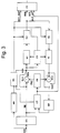
- Fig. 3 shows a block diagram of a subband encoding system similar to the system of Fig. 1, which has been improved according to a preferred embodiment of the invention.
- the system comprises the same blocks and operative connections of Fig. 1, but it further incorporates a redundancy reduction system which is based on prediction.
- the system is similar to what is known as ADPCM, but is modified as described below, for use with audio signals.
- the subband signals SB are compared with respective reconstructed samples, or predictions, PRC, thus obtaining difference signals, or residues, which are themselves fed to the quantizer.
- the reconstructed samples, according to the invention belong to a time instant preceding the instant of the current sample by a variable time (or number of samples), which is determined in each case so that the residue is minimized.
- the choice of the delay is based on the assumption, which is valid in many cases and certainly for musical signals, that the subband signals have quasi-periodic patterns: it is then advantageous to choose a time delay equal to the pseudo-period (or possibly half the pseudoperiod) of the subband signal in the window that is processed at that time.
- An adder SO1 then computes the prediction error between the sample SB and the prediction PRC of that sample (described below), giving rise to an output residue RES.
- Residue RES through a switch SW1, is then normalized in a scaling circuit SC and is quantized in the quantizer QU, identically to Fig. 1.
- Signal RSB at the output of quantizer QU is subjected to inverse quantization in a block IQ, to denormalization in a block IS, and finally to reconstruction of the original signal in a second adder SO2, which adds together the predicted component and the transmitted component, to deliver a co-decoded version, which is loaded to a memory MF through a switch SW2.
- the co-decoded version is fed by memory MF, together with signal SB, to a block CP which computes prediction coefficients PCT and feeds them to a predictor PR for calculation of the prediction.
- the predictor feeds to adder SO1 the above mentioned prediction.
- the prediction coefficients PCT are, in practice, multiplicative factors of the prior samples that are stored in memory MF.
- Predictor PR constructs the prediction of the current sample, using both the prediction coefficients PCT and a parameter D, which is a measure of a delay of the current sample with respect to the prior samples, used for computing the prediction.
- the frame is assembled in formatter FT similarly to the encoder of Fig. 1. However, in this case the signal SWT signifying the use of the prediction is also sent to the formatter for each subband, as well as prediction coefficients PCT and delay parameter D, if the prediction is operative.
- delay parameter D is chosen so that it best approximates the period of the harmonic component where most of the power of the subband signal is concentrated.
- delay parameter D is chosen so that it best approximates the period of the harmonic component where most of the power of the subband signal is concentrated.
- Fig. 5 an exemplary fragment of the waveshape of a subband signal is shown.
- the reason for basing the prediction on a delayed signal resides in the pseudoperiodic nature of many audio signals, and, among these, a class of interest is musical signals.
- the periodicity features of the signal are emphasized by the breakdown into subbands: if a harmonic signal is considered, such as emitted by most musical instruments, if the subbands are narrow enough, a low number of harmonics will fall into each subband, and the signal will tend to be synusoidal. It si therefore apparent that, in these conditions, it is more suitable to use, as a basis for prediction, the coefficients which are co-positioned to the current one in the prior period, rather than those immediately adjacent, which have generally a low correlation.
- the dealy parameter D can be determined in several ways. In the most elementary case, D can be established at a constant value, equal to the center frequency in each subband. In this case, if desired, the incorporation of the values of parameter D in the frame may be dispensed with.
- parameter D is determined by computing the prediction error, in the window under consideration, with a plurality of delay intervals starting from a predetermined minimum value (in practice, 1) up to a predetermined maximum value, and by choosing for the coding the value that gives rise to the minimum prediction error.
- Another method of determining parameter D consists in computing the auto-correlation function of the signal window under consideration, within a variability range of D, and in choosing the value of D corresponding the the maximum of the auto-correlation function.
- Switch SW1 is switched by bit allocator BA so that signal SB is routed to subsequent processing, rather than residue RES, whenever prediction is not advantageous for encoding: in fact, the prediction coefficients and the delay parameter must be transmitted to the decoder if the decoder is to correctly reconstruct the signal, and, where the prediction does not reduce the signal entropy, they would merely cause a waste of bits.
- Switch SW2 is driven parallelly to SW1, and it also cuts out prediction whenever it is not advantageous, so that the prediction error RES is computed by using only information available to the decoder.
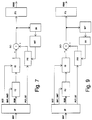
- the decoder shown in Fig. 4, is substantially similar to the lower branch of the diagram of Fig. 3, except that the signal must eventually be fed to a bank of synthesizing filters FS.
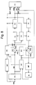
- FIG. 6 A second preferred embodiment of the invention is shown on Fig. 6.
- Block IN comprises an oversampling interpolator as described in Oppenheim and Shafer, implemented according to techniques known in the art, and allowing the number of samples per unit of time to be made denser without altering signal content.
- This feature which allows the prediction to be made from an oversampled signal, a more accurate positioning of the delay can be obtained, since the resolution is increased by the oversampling factor.
- the size of memory MF increases with the chosen oversampling factor.
- block IN can be an interpolator of a more general type, e.g. of mathematical type, i.e., defined by an interpolation function that is evaluated in the required point, as a function of the delay.
- the delay may now take fractional values.
- the memory size need not be increased with this embodiment, but a larger computing power may be required.
- the decoder (Figs. 7 and 9) needs no additional information, but must include the same block IN, in order to be able to reconstruct the signal with the same accuracy of the encoder.
Landscapes
- Engineering & Computer Science (AREA)
- Signal Processing (AREA)
- Computer Networks & Wireless Communication (AREA)
- Computational Linguistics (AREA)
- Health & Medical Sciences (AREA)
- Audiology, Speech & Language Pathology (AREA)
- Human Computer Interaction (AREA)
- Physics & Mathematics (AREA)
- Acoustics & Sound (AREA)
- Multimedia (AREA)
- Compression, Expansion, Code Conversion, And Decoders (AREA)
- Compression Or Coding Systems Of Tv Signals (AREA)
Priority Applications (3)
| Application Number | Priority Date | Filing Date | Title |
|---|---|---|---|
| AT94830509T ATE211869T1 (de) | 1994-10-28 | 1994-10-28 | Teilbandkodierung mit auf tonhöhen basierter prädiktionskodierung in jedem einzelnen teilband |
| DE69429620T DE69429620D1 (de) | 1994-10-28 | 1994-10-28 | Teilbandkodierung mit auf Tonhöhen basierter Prädiktionskodierung in jedem einzelnen Teilband |
| EP94830509A EP0709981B1 (fr) | 1994-10-28 | 1994-10-28 | Codage de signaux en sous-bandes avec codage prédictif basé sur la hauteur du ton dans chaque sous-bande |
Applications Claiming Priority (1)
| Application Number | Priority Date | Filing Date | Title |
|---|---|---|---|
| EP94830509A EP0709981B1 (fr) | 1994-10-28 | 1994-10-28 | Codage de signaux en sous-bandes avec codage prédictif basé sur la hauteur du ton dans chaque sous-bande |
Publications (2)
| Publication Number | Publication Date |
|---|---|
| EP0709981A1 true EP0709981A1 (fr) | 1996-05-01 |
| EP0709981B1 EP0709981B1 (fr) | 2002-01-09 |
Family
ID=8218561
Family Applications (1)
| Application Number | Title | Priority Date | Filing Date |
|---|---|---|---|
| EP94830509A Expired - Lifetime EP0709981B1 (fr) | 1994-10-28 | 1994-10-28 | Codage de signaux en sous-bandes avec codage prédictif basé sur la hauteur du ton dans chaque sous-bande |
Country Status (3)
| Country | Link |
|---|---|
| EP (1) | EP0709981B1 (fr) |
| AT (1) | ATE211869T1 (fr) |
| DE (1) | DE69429620D1 (fr) |
Cited By (5)
| Publication number | Priority date | Publication date | Assignee | Title |
|---|---|---|---|---|
| WO1998042083A1 (fr) * | 1997-03-14 | 1998-09-24 | Nokia Mobile Phones Limited | Appareil et procede de codage audio |
| WO1999004506A1 (fr) * | 1997-07-14 | 1999-01-28 | Fraunhofer-Gesellschaft zur Förderung der angewandten Forschung e.V. | Procede de codage d'un signal audio |
| US6306577B1 (en) | 1998-04-10 | 2001-10-23 | Seikagaku Corporation | Method for measuring enzyme reaction |
| SG99314A1 (en) * | 2000-07-19 | 2003-10-27 | Ct For Signal Proc Nanyang Tec | Method and apparatus for the prediction of audio signals |
| CN111259919A (zh) * | 2018-11-30 | 2020-06-09 | 杭州海康威视数字技术股份有限公司 | 一种视频分类方法、装置及设备、存储介质 |
Families Citing this family (1)
| Publication number | Priority date | Publication date | Assignee | Title |
|---|---|---|---|---|
| DE102010006573B4 (de) * | 2010-02-02 | 2012-03-15 | Rohde & Schwarz Gmbh & Co. Kg | IQ-Datenkompression für Breitbandanwendungen |
Citations (2)
| Publication number | Priority date | Publication date | Assignee | Title |
|---|---|---|---|---|
| US4538234A (en) * | 1981-11-04 | 1985-08-27 | Nippon Telegraph & Telephone Public Corporation | Adaptive predictive processing system |
| EP0424016A2 (fr) * | 1989-10-18 | 1991-04-24 | AT&T Corp. | Codage perceptuel de signaux audio |
-
1994
- 1994-10-28 DE DE69429620T patent/DE69429620D1/de not_active Expired - Lifetime
- 1994-10-28 EP EP94830509A patent/EP0709981B1/fr not_active Expired - Lifetime
- 1994-10-28 AT AT94830509T patent/ATE211869T1/de not_active IP Right Cessation
Patent Citations (2)
| Publication number | Priority date | Publication date | Assignee | Title |
|---|---|---|---|---|
| US4538234A (en) * | 1981-11-04 | 1985-08-27 | Nippon Telegraph & Telephone Public Corporation | Adaptive predictive processing system |
| EP0424016A2 (fr) * | 1989-10-18 | 1991-04-24 | AT&T Corp. | Codage perceptuel de signaux audio |
Cited By (11)
| Publication number | Priority date | Publication date | Assignee | Title |
|---|---|---|---|---|
| WO1998042083A1 (fr) * | 1997-03-14 | 1998-09-24 | Nokia Mobile Phones Limited | Appareil et procede de codage audio |
| AU733156B2 (en) * | 1997-03-14 | 2001-05-10 | Nokia Technologies Oy | Audio coding method and apparatus |
| US6721700B1 (en) | 1997-03-14 | 2004-04-13 | Nokia Mobile Phones Limited | Audio coding method and apparatus |
| US7194407B2 (en) | 1997-03-14 | 2007-03-20 | Nokia Corporation | Audio coding method and apparatus |
| WO1999004506A1 (fr) * | 1997-07-14 | 1999-01-28 | Fraunhofer-Gesellschaft zur Förderung der angewandten Forschung e.V. | Procede de codage d'un signal audio |
| AU723582B2 (en) * | 1997-07-14 | 2000-08-31 | Fraunhofer-Gesellschaft Zur Forderung Der Angewandten Forschung E.V. | Method for coding an audio signal |
| US6424939B1 (en) | 1997-07-14 | 2002-07-23 | Fraunhofer-Gesellschaft Zur Forderung Der Angewandten Forschung E.V. | Method for coding an audio signal |
| US6306577B1 (en) | 1998-04-10 | 2001-10-23 | Seikagaku Corporation | Method for measuring enzyme reaction |
| SG99314A1 (en) * | 2000-07-19 | 2003-10-27 | Ct For Signal Proc Nanyang Tec | Method and apparatus for the prediction of audio signals |
| CN111259919A (zh) * | 2018-11-30 | 2020-06-09 | 杭州海康威视数字技术股份有限公司 | 一种视频分类方法、装置及设备、存储介质 |
| CN111259919B (zh) * | 2018-11-30 | 2024-01-23 | 杭州海康威视数字技术股份有限公司 | 一种视频分类方法、装置及设备、存储介质 |
Also Published As
| Publication number | Publication date |
|---|---|
| ATE211869T1 (de) | 2002-01-15 |
| DE69429620D1 (de) | 2002-02-14 |
| EP0709981B1 (fr) | 2002-01-09 |
Similar Documents
| Publication | Publication Date | Title |
|---|---|---|
| KR100242864B1 (ko) | 디지탈 신호 부호화 장치 및 방법 | |
| US4972484A (en) | Method of transmitting or storing masked sub-band coded audio signals | |
| EP0473367B1 (fr) | Codeur de signal numérique | |
| US6681204B2 (en) | Apparatus and method for encoding a signal as well as apparatus and method for decoding a signal | |
| Tribolet et al. | Frequency domain coding of speech | |
| US4811396A (en) | Speech coding system | |
| US5125030A (en) | Speech signal coding/decoding system based on the type of speech signal | |
| EP0582921B1 (fr) | Codeur de signal audio à faible retard, utilisant des techniques d'analyse par synthèse | |
| EP0154381B1 (fr) | Codeur digital de la parole avec codage d'une bande de base du résidu de prédiction | |
| EP0966793B1 (fr) | Appareil et procede de codage audio | |
| EP0152430B1 (fr) | Appareil et procedes de codage, decodage, analyse et synthese d'un signal | |
| EP0799531B1 (fr) | Procede et appareil pour appliquer une prediction des formes d'onde a des sous-bandes d'un systeme de codage perceptif | |
| JPS6161305B2 (fr) | ||
| US5054073A (en) | Voice analysis and synthesis dependent upon a silence decision | |
| US3715512A (en) | Adaptive predictive speech signal coding system | |
| EP0772925B1 (fr) | Quantification non lineaire d'un signal d'information | |
| US4991215A (en) | Multi-pulse coding apparatus with a reduced bit rate | |
| CA1144650A (fr) | Codage de signaux predictifs avec quantification a division | |
| US4319082A (en) | Adaptive prediction differential-PCM transmission method and circuit using filtering by sub-bands and spectral analysis | |
| EP0709981B1 (fr) | Codage de signaux en sous-bandes avec codage prédictif basé sur la hauteur du ton dans chaque sous-bande | |
| JPH05173599A (ja) | 音声符号復号化装置 | |
| KR0167769B1 (ko) | 디지탈 신호 처리장치 | |
| US5675703A (en) | Apparatus for decoding compressed and coded sound signal | |
| KR0152016B1 (ko) | 가변 비트할당을 이용한 부호화 및 복호화시스템 | |
| KR0144841B1 (ko) | 음향신호의 적응적 부호화 및 복호화장치 |
Legal Events
| Date | Code | Title | Description |
|---|---|---|---|
| PUAI | Public reference made under article 153(3) epc to a published international application that has entered the european phase |
Free format text: ORIGINAL CODE: 0009012 |
|
| AK | Designated contracting states |
Kind code of ref document: A1 Designated state(s): AT BE CH DE DK ES FR GB GR IT LI NL PT SE |
|
| 17P | Request for examination filed |
Effective date: 19960507 |
|
| GRAG | Despatch of communication of intention to grant |
Free format text: ORIGINAL CODE: EPIDOS AGRA |
|
| 17Q | First examination report despatched |
Effective date: 20010206 |
|
| GRAG | Despatch of communication of intention to grant |
Free format text: ORIGINAL CODE: EPIDOS AGRA |
|
| GRAH | Despatch of communication of intention to grant a patent |
Free format text: ORIGINAL CODE: EPIDOS IGRA |
|
| GRAH | Despatch of communication of intention to grant a patent |
Free format text: ORIGINAL CODE: EPIDOS IGRA |
|
| GRAA | (expected) grant |
Free format text: ORIGINAL CODE: 0009210 |
|
| REG | Reference to a national code |
Ref country code: GB Ref legal event code: IF02 |
|
| AK | Designated contracting states |
Kind code of ref document: B1 Designated state(s): AT BE CH DE DK ES FR GB GR IT LI NL PT SE |
|
| PG25 | Lapsed in a contracting state [announced via postgrant information from national office to epo] |
Ref country code: NL Free format text: LAPSE BECAUSE OF FAILURE TO SUBMIT A TRANSLATION OF THE DESCRIPTION OR TO PAY THE FEE WITHIN THE PRESCRIBED TIME-LIMIT Effective date: 20020109 Ref country code: LI Free format text: LAPSE BECAUSE OF FAILURE TO SUBMIT A TRANSLATION OF THE DESCRIPTION OR TO PAY THE FEE WITHIN THE PRESCRIBED TIME-LIMIT Effective date: 20020109 Ref country code: GR Free format text: LAPSE BECAUSE OF FAILURE TO SUBMIT A TRANSLATION OF THE DESCRIPTION OR TO PAY THE FEE WITHIN THE PRESCRIBED TIME-LIMIT Effective date: 20020109 Ref country code: FR Free format text: LAPSE BECAUSE OF FAILURE TO SUBMIT A TRANSLATION OF THE DESCRIPTION OR TO PAY THE FEE WITHIN THE PRESCRIBED TIME-LIMIT Effective date: 20020109 Ref country code: CH Free format text: LAPSE BECAUSE OF FAILURE TO SUBMIT A TRANSLATION OF THE DESCRIPTION OR TO PAY THE FEE WITHIN THE PRESCRIBED TIME-LIMIT Effective date: 20020109 Ref country code: BE Free format text: LAPSE BECAUSE OF FAILURE TO SUBMIT A TRANSLATION OF THE DESCRIPTION OR TO PAY THE FEE WITHIN THE PRESCRIBED TIME-LIMIT Effective date: 20020109 Ref country code: AT Free format text: LAPSE BECAUSE OF FAILURE TO SUBMIT A TRANSLATION OF THE DESCRIPTION OR TO PAY THE FEE WITHIN THE PRESCRIBED TIME-LIMIT Effective date: 20020109 |
|
| REF | Corresponds to: |
Ref document number: 211869 Country of ref document: AT Date of ref document: 20020115 Kind code of ref document: T |
|
| REG | Reference to a national code |
Ref country code: CH Ref legal event code: EP |
|
| REF | Corresponds to: |
Ref document number: 69429620 Country of ref document: DE Date of ref document: 20020214 |
|
| PG25 | Lapsed in a contracting state [announced via postgrant information from national office to epo] |
Ref country code: SE Free format text: LAPSE BECAUSE OF FAILURE TO SUBMIT A TRANSLATION OF THE DESCRIPTION OR TO PAY THE FEE WITHIN THE PRESCRIBED TIME-LIMIT Effective date: 20020409 Ref country code: PT Free format text: LAPSE BECAUSE OF FAILURE TO SUBMIT A TRANSLATION OF THE DESCRIPTION OR TO PAY THE FEE WITHIN THE PRESCRIBED TIME-LIMIT Effective date: 20020409 Ref country code: DK Free format text: LAPSE BECAUSE OF FAILURE TO SUBMIT A TRANSLATION OF THE DESCRIPTION OR TO PAY THE FEE WITHIN THE PRESCRIBED TIME-LIMIT Effective date: 20020409 |
|
| PG25 | Lapsed in a contracting state [announced via postgrant information from national office to epo] |
Ref country code: DE Free format text: LAPSE BECAUSE OF FAILURE TO SUBMIT A TRANSLATION OF THE DESCRIPTION OR TO PAY THE FEE WITHIN THE PRESCRIBED TIME-LIMIT Effective date: 20020410 |
|
| NLV1 | Nl: lapsed or annulled due to failure to fulfill the requirements of art. 29p and 29m of the patents act | ||
| REG | Reference to a national code |
Ref country code: CH Ref legal event code: PL |
|
| PG25 | Lapsed in a contracting state [announced via postgrant information from national office to epo] |
Ref country code: ES Free format text: LAPSE BECAUSE OF FAILURE TO SUBMIT A TRANSLATION OF THE DESCRIPTION OR TO PAY THE FEE WITHIN THE PRESCRIBED TIME-LIMIT Effective date: 20020730 |
|
| PG25 | Lapsed in a contracting state [announced via postgrant information from national office to epo] |
Ref country code: GB Free format text: LAPSE BECAUSE OF NON-PAYMENT OF DUE FEES Effective date: 20021028 |
|
| EN | Fr: translation not filed | ||
| PLBE | No opposition filed within time limit |
Free format text: ORIGINAL CODE: 0009261 |
|
| STAA | Information on the status of an ep patent application or granted ep patent |
Free format text: STATUS: NO OPPOSITION FILED WITHIN TIME LIMIT |
|
| 26N | No opposition filed | ||
| NLV1 | Nl: lapsed or annulled due to failure to fulfill the requirements of art. 29p and 29m of the patents act | ||
| GBPC | Gb: european patent ceased through non-payment of renewal fee | ||
| PGFP | Annual fee paid to national office [announced via postgrant information from national office to epo] |
Ref country code: IT Payment date: 20121023 Year of fee payment: 19 |
|
| PG25 | Lapsed in a contracting state [announced via postgrant information from national office to epo] |
Ref country code: IT Free format text: LAPSE BECAUSE OF NON-PAYMENT OF DUE FEES Effective date: 20131028 |