EP0709809B1 - Gerät und Verfahren zur Kodierung und Dekodierung von Bildern unter Verwendung einer Kantensynthese und einer Wavelet-Rücktransformation - Google Patents
Gerät und Verfahren zur Kodierung und Dekodierung von Bildern unter Verwendung einer Kantensynthese und einer Wavelet-Rücktransformation Download PDFInfo
- Publication number
- EP0709809B1 EP0709809B1 EP95307558A EP95307558A EP0709809B1 EP 0709809 B1 EP0709809 B1 EP 0709809B1 EP 95307558 A EP95307558 A EP 95307558A EP 95307558 A EP95307558 A EP 95307558A EP 0709809 B1 EP0709809 B1 EP 0709809B1
- Authority
- EP
- European Patent Office
- Prior art keywords
- image
- edge
- decoded
- reduced
- images
- Prior art date
- Legal status (The legal status is an assumption and is not a legal conclusion. Google has not performed a legal analysis and makes no representation as to the accuracy of the status listed.)
- Expired - Lifetime
Links
- 238000000034 method Methods 0.000 title claims description 100
- 230000015572 biosynthetic process Effects 0.000 title claims description 31
- 238000003786 synthesis reaction Methods 0.000 title claims description 31
- 239000013598 vector Substances 0.000 claims description 114
- 238000005070 sampling Methods 0.000 claims description 87
- 238000009499 grossing Methods 0.000 claims description 86
- 238000001914 filtration Methods 0.000 claims description 68
- 230000015654 memory Effects 0.000 claims description 59
- 230000002194 synthesizing effect Effects 0.000 claims description 10
- 230000008859 change Effects 0.000 claims description 6
- 230000003247 decreasing effect Effects 0.000 claims 1
- 238000010586 diagram Methods 0.000 description 29
- 230000008569 process Effects 0.000 description 25
- 238000003708 edge detection Methods 0.000 description 12
- 230000008901 benefit Effects 0.000 description 11
- 230000006835 compression Effects 0.000 description 9
- 238000007906 compression Methods 0.000 description 9
- 238000013139 quantization Methods 0.000 description 8
- 238000009966 trimming Methods 0.000 description 8
- 230000006870 function Effects 0.000 description 5
- 230000008719 thickening Effects 0.000 description 5
- 230000000295 complement effect Effects 0.000 description 4
- 238000009825 accumulation Methods 0.000 description 3
- 230000002457 bidirectional effect Effects 0.000 description 3
- 238000013467 fragmentation Methods 0.000 description 3
- 238000006062 fragmentation reaction Methods 0.000 description 3
- 230000005540 biological transmission Effects 0.000 description 2
- 238000004422 calculation algorithm Methods 0.000 description 2
- 238000004891 communication Methods 0.000 description 2
- 230000007423 decrease Effects 0.000 description 2
- 230000000694 effects Effects 0.000 description 2
- 230000001788 irregular Effects 0.000 description 2
- 230000009467 reduction Effects 0.000 description 2
- 230000002441 reversible effect Effects 0.000 description 2
- 239000004065 semiconductor Substances 0.000 description 2
- 238000004458 analytical method Methods 0.000 description 1
- 230000001447 compensatory effect Effects 0.000 description 1
- 238000001514 detection method Methods 0.000 description 1
- 230000010339 dilation Effects 0.000 description 1
- 238000006073 displacement reaction Methods 0.000 description 1
- 230000012447 hatching Effects 0.000 description 1
- 230000001771 impaired effect Effects 0.000 description 1
- 230000000717 retained effect Effects 0.000 description 1
- 230000005236 sound signal Effects 0.000 description 1
- 230000002123 temporal effect Effects 0.000 description 1
Images









Classifications
-
- H—ELECTRICITY
- H04—ELECTRIC COMMUNICATION TECHNIQUE
- H04N—PICTORIAL COMMUNICATION, e.g. TELEVISION
- H04N19/00—Methods or arrangements for coding, decoding, compressing or decompressing digital video signals
- H04N19/85—Methods or arrangements for coding, decoding, compressing or decompressing digital video signals using pre-processing or post-processing specially adapted for video compression
-
- H—ELECTRICITY
- H04—ELECTRIC COMMUNICATION TECHNIQUE
- H04N—PICTORIAL COMMUNICATION, e.g. TELEVISION
- H04N19/00—Methods or arrangements for coding, decoding, compressing or decompressing digital video signals
- H04N19/50—Methods or arrangements for coding, decoding, compressing or decompressing digital video signals using predictive coding
- H04N19/503—Methods or arrangements for coding, decoding, compressing or decompressing digital video signals using predictive coding involving temporal prediction
- H04N19/51—Motion estimation or motion compensation
- H04N19/537—Motion estimation other than block-based
-
- H—ELECTRICITY
- H04—ELECTRIC COMMUNICATION TECHNIQUE
- H04N—PICTORIAL COMMUNICATION, e.g. TELEVISION
- H04N19/00—Methods or arrangements for coding, decoding, compressing or decompressing digital video signals
- H04N19/60—Methods or arrangements for coding, decoding, compressing or decompressing digital video signals using transform coding
- H04N19/63—Methods or arrangements for coding, decoding, compressing or decompressing digital video signals using transform coding using sub-band based transform, e.g. wavelets
-
- H—ELECTRICITY
- H04—ELECTRIC COMMUNICATION TECHNIQUE
- H04N—PICTORIAL COMMUNICATION, e.g. TELEVISION
- H04N19/00—Methods or arrangements for coding, decoding, compressing or decompressing digital video signals
- H04N19/30—Methods or arrangements for coding, decoding, compressing or decompressing digital video signals using hierarchical techniques, e.g. scalability
- H04N19/39—Methods or arrangements for coding, decoding, compressing or decompressing digital video signals using hierarchical techniques, e.g. scalability involving multiple description coding [MDC], i.e. with separate layers being structured as independently decodable descriptions of input picture data
Definitions
- This invention relates to a compressive image encoding and decoding method using edge synthesis and the inverse wavelet transform, and to digital image encoding and decoding devices employing this method.
- Compression is essential for efficient storage and transmission of digitized images. Compression methods have been described by the Joint Photographic Experts Group (JPEG) for still images, and the Motion Picture Experts Group (MPEG) for moving images.
- JPEG Joint Photographic Experts Group
- MPEG Motion Picture Experts Group
- the JPEG method involves a discrete cosine transform (DCT), followed by quantization and variable-length encoding.
- DCT discrete cosine transform
- the MPEG method involves detecting motion vectors. Both methods require substantial computation, the detection of motion vectors being particularly demanding.
- This transform employs a family of wavelets related by dilation and translation; that is, the family consists of occurrences of the same basic wavelet at different locations and on different scales. If the scales form a progressively doubling sequence, and if the basic wavelet is zero everywhere except in a limited domain, wavelet transforms and inverse wavelet transforms can be carried out with efficient computational algorithms.
- a wavelet transform can be described as a filtering process executed at each wavelet scale.
- a digitized image for example, is transformed by filtering with the basic wavelet, then with the basic wavelet dilated by a factor of two, then with the basic wavelet dilated by a factor of four, and so on.
- One prior-art wavelet encoding scheme employs a complementary pair of wavelets to divide an image into a high-frequency component and a low-frequency component. These components contain information about variations on scales respectively less than and greater than a certain cut-off scale. This process is iterated on the low-frequency component with a doubling of the wavelet scale, obtaining new low-frequency and high-frequency components, then iterated again on the new low-frequency component, and so on. After a certain number of iterations, the components are encoded by an encoding scheme that works from low-toward high-frequency information. This scheme enables accurate image reconstruction, but retains too much high-frequency information to achieve high compression ratios.
- Another prior-art wavelet encoding scheme employs a basic wavelet that is the first derivative of a smoothing filter (that is, the first derivative of a low-pass filtering function).
- This type of wavelet acts as a high-pass filter.
- High-frequency information is obtained by detecting local peaks (local maxima of absolute values) in the result of the wavelet transform, which correspond to edges in the original image.
- the size and location of the peak values at a selected scale are encoded, along with a low-frequency image obtained by smoothing at the largest scale of the wavelet transform. Fairly high compression ratios can be obtained in this way.
- this prior-art method employs an algorithm derived from a mathematical procedure involving iterated projections in Hilbert space. Under ideal conditions, the projections converge toward a unique set of data that (i) have the required local peak values and (ii) are within the range of the wavelet transform operator. An inverse wavelet transform is then carried out on the converged data to obtain the original image.
- edge-based encoding schemes in general is that encoding efficiency tends to be impaired by edge fragmentation and irregularity.
- the present invention seeks to provide an improved method of encoding and decoding.
- a method of encoding and decoding a digitized image consisting of pixels having pixel values comprising the steps of detecting sharpness of edges in said digitized image, and assigning corresponding sharpness values to said pixels; encoding position and sharpness values of pixels having sharpness values exceeding a certain threshold, thereby generating edge image information; repeatedly filtering and down-sampling said digitized image, using a cascaded series of two-dimensional smoothing and down-sampling filters, thereby generating a reduced image; encoding said reduced image, thereby generating reduced image information; sending said edge image information and said reduced image information to an input/output device; receiving said edge image information and said reduced image information from said input/output device; generating from the edge image information received from said input/output device a first set of decoded edge images, including at least a first decoded horizontal edge image and a first decoded vertical edge image; filtering and down-sampling said first set of decoded edge images, using
- a (two-dimensional) digitized image is an array of pixels having values x(i, j), where the horizontal coordinate i and vertical coordinate j range over sets of integers. The range of these coordinates is the size of the image, i.e., the number of pixels in the horizontal and vertical directions.
- the pixel values represent, for example, intensity gradations.
- a one-dimensional image is a horizontal or vertical line in a two-dimensional digitized image, i.e., a set of pixels with values x(i) indexed by a single coordinate.
- a standard edge is a one-dimensional image having just one sharp variation point.
- An example would be an image with pixel values that change first at one constant rate, then at a different constant rate, such as the following: ... 2.0 1.5 1.0 0.5 0 0.5 1.0 1.5 2.0 ...
- a standard edge serves as a basic model for all the edges occurring in a digitized image.
- Down-sampling a digitized image means reducing its size by a process generally analogous to photographic reduction: by selecting every n-th pixel, for example, where n is a suitable integer. Up-sampling means increasing the size of an image by interpolating new pixels between the existing pixels.
- a (one-dimensional) filter is a set of coefficients f(k), where k ranges over the integers.
- the non-zero coefficients f(k) are the taps of the filter.
- the Fourier transform F of a filter f is defined as follows, where summation is over all taps, e is the natural logarithm base, and j is the square root of minus one.
- the Fourier transform of f* is therefore the complex conjugate of the Fourier transform of f.
- a filter has even symmetry around zero if it is equal to its own conjugate.
- Filters satisfying these exact reconstruction conditions are well known in the wavelet transform art.
- a pair of filters satisfying the second exact reconstruction condition above is referred to as a complementary pair.
- a filter f To filter a one-dimensional image x by a filter f means to obtain a new one-dimensional image y with the following pixel intensities:
- Filtering can be done two-dimensionally by, for example, filtering first in the horizontal direction, then in the vertical direction, or vice versa.
- a high-pass filter is a filter that retains small-scale variations and rejects large-scale variations.
- a low-pass filter rejects small-scale variations and retains large-scale variations.
- Smoothing filter is a synonym for low-pass filter.
- the cut-off frequency of a high-pass or low-pass filter indicates the scale that divides the retained variations from the rejected variations.
- a lower cut-off frequency corresponds to a larger scale of variations.
- Frequency actually refers to the variable ⁇ in the Fourier transform F( ⁇ ) of the filter.
- the digital image encoder in the first embodiment comprises an input terminal 10, a two-dimensional smoothing and down-sampling section 20, and an edge detector 21.
- the digital image encoder also comprises an edge image encoder 24, a reduced image encoder 25, and a multiplexer 26, which together constitute an encoding section 27.
- a digitized image X 0 is input from the input terminal 10 to the edge detector 21 and first smoothing filter 22-1.
- Smoothing filter 22-1 outputs a filtered image X 1 to the next smoothing filter 22-2, and this process continues, each smoothing filter 22-m filtering the image X m-1 received from the preceding smoothing filter and furnishing a new filtered image X m to the next smoothing filter, until the last smoothing filter 22-n is reached.
- the last smoothing filter 22-n outputs a low-frequency image X n to the down sampler 23, which outputs a reduced image R to the reduced image encoder 25.
- the reduced image encoder 25 encodes the reduced image R to obtain reduced image information Cr.
- the edge detector 21 detects edge points in the input image X 0 and outputs horizontal and vertical edge images Sh and Sv to the edge image encoder 24 in the encoding section 22.
- the edge image encoder 24 encodes these edge images to obtain edge image information Cs.
- the multiplexer 26 combines the reduced image information Cr and edge image information Cs into an encoded image C, which is output to a first input/output device 28 such as a communication channel, semiconductor memory, or magnetic disk storage device.
- the digital image decoder has a decoding section 29 comprising a demultiplexer 30, an edge image decoder 31, and a reduced image decoder 32.
- the demultiplexer 30 receives the encoded image C from the first input/output device 28 and separates it into edge image information Cs, which it supplies to the edge image decoder 31, and reduced image information Cr, which it supplies to the reduced image decoder 32.
- the reduced image decoder 32 decodes Cr to obtain a decoded reduced image R', which the up sampler 35 enlarges to obtain a decoded low-frequency image X' n .
- the first inverse wavelet processor 36-n in the cascade receives the decoded low-frequency image X' n from the up sampler 35.
- the last inverse wavelet processor 36-1 outputs the fully reconstructed image X' 0 to a second input/output device 37.
- Each of the elements in the FIGs. 1 and 2 comprises a memory for storing data and well-known circuits for performing arithmetic and logic operations. Descriptions of the circuit configurations will be omitted to avoid obscuring the invention with irrelevant detail.
- the entire digital image encoder can be fabricated as a single semiconductor integrated circuit, or can be built from a small number of such circuits; likewise the digital image decoder.
- the invention can also be practiced by providing a general-purpose processor such as a microprocessor or digital signal processor with memory for storing data and programs for executing the functions of the individual elements in FIG. 1 or FIG. 2.
- the input image X 0 is a digitized image with pixel values X 0 (i, j).
- the edge detector 21 detects edges by detecting variations in the rate of change of pixel values from pixel to pixel. More specifically, the edge detector 21 takes differences between adjacent pixel values, then takes differences between these differences, and finally performs a thresholding operation to reduce small differences to zero. This process is carried out separately in the horizontal and vertical directions.
- Equivalent edge detection could be performed by filtering the image X 0 with a second-derivative filter having coefficients (1, -2, 1), but taking differences of differences is preferable because it requires less computation.
- the detected value Sh(i, j) is the edge sharpness at pixel (i, j), also referred to as the edge size.
- Edge sharpness values with absolute values equal to or less than a certain threshold value T are quantized to zero. Values exceeding T are also quantized, to reduce the number of bits in the edge-image data; then the quantized sharpness values Sh(i, j) at all pixels are output as the horizontal edge image Sh.
- > T, are referred to as edge points.
- the meaning of the edge sharpness computation can be seen in FIG. 3.
- the horizontal axis represents, for example, the horizontal direction in the image, and the vertical axis represents the pixel value.
- the difference between pixel values 38 and 39 is -A
- the difference between pixel values 40 and 38 is B
- the other pixels in FIG. 3 have zero sharpness.
- FIG. 3 thus illustrates a standard edge, with just one sharp variation.
- the vertical edge image is generated in the same way, by taking differences in the vertical direction, then taking differences of these differences.
- the vertical edge image is quantized as was the horizontal edge image, points for which
- Quantization can be performed by dividing the edge sharpness values by a power of two, for example, or by using a quantization table.
- Sh and Sv will be employed herein to denote edge sharpness values both before and after quantization.
- Smoothing filter 22-1 employs a low-pass filter h 1 with even symmetry and a certain number of taps.
- this filter either has 2N + 1 taps and is symmetric around zero, or has 2N taps and is symmetric around 1/2, where N is an appropriate positive integer.
- the smoothing filter 22-1 performs a two-dimensional low-pass filtering operation by filtering the input image X 0 with h 1 horizontally and vertically, obtaining:
- the other smoothing filters 22-m (m > 1) also employ low-pass filters h m with even symmetry, and with tap coefficients summing to plus or minus one.
- image X m-1 is filtered horizontally and vertically by filter h m to obtain image X m .
- filter h m As the image passes through the cascade, variations on progressively larger scales are smoothed out, and resolution of fine detail decreases correspondingly.
- the low-pass filters h m (m > 1) are obtained by doubling the tap spacing as described above, they will pass high-frequency variations in certain regions above their cut-off frequencies. This is allowable because those high-frequency variations will already have been removed by previous filters in the cascade.
- the down sampler 23 down-samples the low-frequency image X n output by the smoothing filter 22-n, thereby reducing the amount of image data.
- the reduced image R output by the down sampler 23 resembles a photographic reduction of the original image X 0 .
- the edge image encoder 24 encodes the quantized horizontal and vertical edge images Sh and Sv by using, for example, run-length encoding to encode the positions of edge points, and differential encoding to encode the sharpness values at these points.
- chain encoding can be used to encode the edge positions, taking advantage of the fact that edge points tend to be organized into chains of mutually contiguous points. Chain encoding encodes only the displacement from one position to the next in such a chain.
- the reduced image encoder 25 encodes the reduced image R by, for example, performing a discrete cosine transform, quantizing the resulting DCT coefficients, and encoding them in zig-zag order by a variable-length encoding method.
- the reduced image R can be encoded by a predictive encoding method similar to the differential pulse-code modulation method (DPCM) commonly employed for audio signals, or by any other suitable method.
- DPCM differential pulse-code modulation method
- the encoded image C consisting of the edge image information Cs and low-frequency information Cr as multiplexed by the multiplexer 26, is output to the first input/output device 28 for transmission or storage.
- the amount of encoded data is generally reduced to a small fraction of the amount in the original image X 0 , so the encoded image C can be efficiently transmitted or stored.
- These filters g m can be obtained from g 1 by successively doubling the tap spacing, in the same way that the filters h m were obtained from h 1 .
- Filter f m is a completion filter, defined in terms of its Fourier transform F m as follows.
- F m ( ⁇ ) 1 + H m ( ⁇ ) 2 2
- Filter e m is an edge synthesis filter derived by filtering a standard edge of unit sharpness by the corresponding high-pass filter g m .
- g m has even symmetry, all standard edges with unit sharpness lead to the same e m , which has the following tap values e m (t).
- decoders 31 and 32 carry out processes that are reverse to the processes performed by encoders 24 and 25 in FIG. 1. For example, if the reduced image encoder 25 in FIG. 1 performed a discrete cosine transform followed by quantization and variable-length encoding, the reduced image decoder 32 in FIG. 2 performs variable-length decoding, dequantization, then an inverse discrete cosine transform to obtain the decoded reduced image R'.
- the edge image decoder 31 performs run-length or chain decoding to recover the edge positions and an accumulation process to obtain the sharpness values.
- the edge image decoder 31 also dequantizes the sharpness values.
- the up sampler 35 obtains the decoded low-frequency image X' n by restoring the decoded reduced image R' to the original image size (the size of the edge images and high-frequency images). If, for example, each pixel value in the reduced image R represented an M x M block in the low-frequency image X n , the up sampler 35 can simply copy this value to all pixels in the corresponding M x M block of the decoded low-frequency image X' 1 . More sophisticated up-sampling methods involving interpolation can also be employed, but smooth interpolation is not required, because the image will be smoothed during the inverse wavelet transform.
- Each edge synthesizer 34-m filters the corresponding horizontal edge image Sh m by the edge synthesis filter e m in the horizontal direction, and the vertical edge image Sv m by e m in the vertical direction.
- the smoothing filters h m have an odd number of taps and the high-pass filters g m accordingly have even symmetry
- the resulting horizontal and vertical high-frequency images Yh m and Yv m can be described by the following equations:
- the edge synthesizer 34 synthesizes the result of filtering a standard edge of the corresponding sharpness by the high-frequency filter g m . It then adds these results together for all edge points to synthesize a high-frequency image.
- the smoothing filters h m have an even number of taps and the high-pass filters g m accordingly have odd symmetry, it is advantageous to carry out the edge synthesis indirectly.
- the results of filtering different standard edges by the same g m need not be the same.
- the resulting edge synthesis filters e m can have an unlimited number of non-zero taps.
- the horizontal edge image Sh m is first filtered horizontally by de m (t) to obtain a horizontal differential high-frequency image ⁇ Yh, and the vertical edge image Sv m is filtered vertically with de m (t) to obtain a vertical differential high-frequency image ⁇ Yv.
- each inverse wavelet processor 36-m performs three two-dimensional filtering operations, using the conjugate filters f* m , g* m , and h* m of f m , g m , and h m .
- the image X' m is filtered by h* m horizontally and vertically
- the horizontal high-frequency image Yh* m is filtered by g* m horizontally and f* m vertically
- the vertical high-frequency image Yv m is filtered by g* m vertically and f* m horizontally.
- This inverse wavelet transform is well known in the art, and is described by the following equation:
- the reconstructed image X' 0 is output to the second input/output device 37 for display or print-out.
- the reconstructed image can be output to a computer for further image processing.
- Synthesizing high-frequency image information from edge images as described above enables high compression ratios to be obtained.
- High-frequency information corresponding to edges below the sharpness threshold T is lost, so there is some loss of low-level, high-frequency shading variations, but the reconstructed image is not distorted, and sharp edges are faithfully preserved.
- edge detection is performed only at the original image scale, which permits edge detection to proceed concurrently with the smoothing filtering and down-sampling operations in the encoder, to speed up the encoding process.
- edge detection is performed only at the original image scale, which permits edge detection to proceed concurrently with the smoothing filtering and down-sampling operations in the encoder, to speed up the encoding process.
- high-frequency images are synthesized in a single step at each wavelet scale, without recourse to iterative procedures. This reduces the computational load in the decoder, speeds up the decoding process, and eliminates the prior-art problem of deciding when to stop iterating.
- the second embodiment is similar to the first, but incorporates a down-sampling process into each of the smoothing filters in the encoder and decoder, and an up-sampling process into each of the inverse wavelet processors in the decoder.
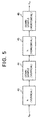
- FIG. 5 shows a conceptual flow diagram of the smoothing and down-sampling filtering process.
- the first step 43 is a vertical smoothing step carried out using a low-pass filter h identical to filter h 1 in the first embodiment.
- the second step 44 is a vertical down-sampling step that discards every other pixel in the vertical direction.
- the third step 45 is a horizontal smoothing step in which the remaining image data are filtered by the same filter h in the horizontal direction.
- the fourth step 46 is a horizontal down-sampling step that discards every other pixel in the horizontal direction.
- This operation reduces the size of the image by a factor of two in both the horizontal and vertical directions.
- h d denotes filtering by h followed by down-sampling as described above.
- FIG. 6 shows the digital image decoder of the second embodiment.
- the decoding section 29 is the same as in the first embodiment.
- the output of the reduced image decoder 32 is now denoted X' n , but is similar to the output R in the first embodiment.
- the decoder employs filters e, f, g, and h that are identical to e 1 , f 1 , g 1 , and h 1 in the first embodiment.
- the subscripts d and u attached to these filters denote associated down-sampling and up-sampling operations, respectively.
- Each filter 48-m filters and smooths each input edge image Sv m and Sh m in both the vertical and horizontal directions, and down-samples the result by a factor of two in both directions to generate edge images Sv m+1 and Sh m+1 . Due to the down-sampling, Sv m+1 is only half as wide and half as high as Sv m , and Sh m+1 is only half as wide and half as high as Sh m .
- the vertical edge image Sv m is down-sampled by a factor of two in the horizontal direction, filtered by the above-mentioned filter e in the vertical direction, then down-sampled by a factor of two in the vertical direction
- the horizontal edge image Sh m is down-sampled by a factor of two in the vertical direction, filtered by filter e in the horizontal direction, then down-sampled by a factor of two in the horizontal direction.
- Processors 50-m use the conjugate filters f*, g*, and h* to perform the same computation as in the first embodiment, but each filtering step in the computation is preceded by an up-sampling step.
- These up-sampling steps double the image size by inserting zero-valued pixels between every pair of adjacent pixels in the appropriate direction. To prevent the zero-valued pixels from reducing the mean value of the output image, after each filtering step, the resulting pixel values are doubled.
- the image X' m-1 output from inverse wavelet processor 50-m is twice as wide and twice as high as each of the three images X' m , Yv m , and Yh m input to processor 50-m.
- the three input images X' m , Yv m , and Yh m all have the same size.
- FIG. 8 depicts the operation performed by the inverse wavelet processor 50-m schematically.
- the partially reconstructed image X' m received from the preceding processor 50-(m + 1) in the cascade is up-sampled horizontally by interpolating zeros (reducing the mean pixel value by a factor of two) and filtered horizontally by h*; then the resulting pixel values are doubled (restoring the correct mean value).
- the image is now up-sampled vertically, again by interpolating zeros, and filtered by h* vertically.
- high-frequency image Yh m is up-sampled vertically, filtered by f* vertically, doubled in pixel value, up-sampled horizontally, and filtered by g* horizontally.
- High-frequency image Yv m is up-sampled horizontally, filtered by f* horizontally, doubled in pixel value, up-sampled vertically, and filtered by g* vertically.
- the three resulting images are then added together to produce a sum image, all pixel values in which are again doubled to counteract the effect of the second up-sampling steps.
- the final result is the partially reconstructed image X' m-1 which is passed to the next wavelet processor 50-(m - 1), or the reconstructed image X' 0 output to the input/output device 37.
- inverse wavelet processor 50-m The operation performed by inverse wavelet processor 50-m can be described by the following equation. Up-sampling is accomplished by dividing the values of i, j, k, and 1 by two. If either i/2 + k/2 or j/2 + 1/2 is not an integer, the corresponding values of X' m , Yh m , and Yv m are taken to be zero.
- the second embodiment provides the same advantages as the first embodiment but requires less computation, because the amount of image data to be processed is reduced by a factor of four (by a factor of two horizontally and another factor of two vertically) at each wavelet scale.
- the third embodiment detects edges diagonally as well as horizontally and vertically. To prevent an increase in the amount of encoded data, some of the down-sampling steps that were performed in the decoder in the second embodiment are moved into the encoder.
- FIG. 9 is a block diagram of the digital image encoder of the third embodiment.
- the two-dimensional smoothing and down-sampling section 41 is the same as in the second embodiment.
- the original image X 0 is also input to a one-dimensional smoothing and down-sampling section 51, which outputs the original image X 0 together with a vertically smoothed and down-sampled image Xh and a horizontally smoothed and down-sampled image Xv to an edge detector 52.
- the edge detector 52 outputs three edge images Sh, Sv, and Sc to the encoding section 27, which is the same as in the first two embodiments.
- FIG. 10 illustrates the processes carried out in the one-dimensional smoothing and down-sampling section 51.
- Image Xv is produced by filtering the original image X 0 with the low-pass filter h in the horizontal direction, then down-sampling the resulting image by removing every other pixel in the horizontal direction.
- Image Xv accordingly contains only half as much data as image X 0 .
- image Xh is produced by filtering X 0 vertically with the low-pass filter h, then down-sampling the result by removing every other pixel in the vertical direction.
- Image Xh also contains only half as much data as image X 0 .
- the edge detector 52 detects edges by the method described earlier: by taking differences between adjacent pixels, then taking differences between these differences. This method is applied in the directions that have not been down-sampled. Accordingly, differences are taken horizontally in the vertically down-sampled image Xh, producing a horizontal edge image Sh. Similarly, differences are taken vertically in the horizontally down-sampled image Xv, producing a vertical edge image Sv.
- Edges are detected diagonally by processing the original image X 0 in both the horizontal and vertical directions.
- the difference-of-differences operation is first performed on X 0 in, for example, the horizontal direction, producing an intermediate image.
- the difference-of-differences operation is next performed on this intermediate image in the vertical direction.
- Resulting pixels with absolute values equal to or less than a threshold value T are then set to zero, and other values are suitably quantized, producing a diagonal edge image Sc.
- the edge image encoder 24 can encode the diagonal edge image Sc by methods similar to those used for the vertical and horizontal edge images Sv and Sh. Sc has the same size as the original image X 0 , while Sv and Sh are only half this size, so the total amount of data to be encoded is the same as in the first two embodiments.
- FIG. 11 is a block diagram of the digital image decoder in the third embodiment.
- the decoding section 29 is the same as in the preceding embodiments, except that the edge image decoder 31 outputs a set of three edge images, Sv 1 , Sh 1 , and Sc 1 , corresponding to the encoded edge images Sv, Sh, and Sc.
- Edge synthesizer 54-m operates as illustrated in FIG. 12, using the same edge synthesis filter e as in the second embodiment.
- the vertical edge image Sv m is filtered vertically by e, then down-sampled by removing every other pixel in the vertical direction to create a vertical high-frequency image Yv m .
- the horizontal edge image Sh m is filtered horizontally by e, then down-sampled horizontally to create a horizontal high-frequency image Yh m .
- the diagonal edge image Sc m is filtered vertically by e, down-sampled in the vertical direction, filtered horizontally by e, then down-sampled in the horizontal direction, creating a diagonal high-frequency image Yc m .
- the three high-frequency images Yv m , Yh m , and Yc m are all the same size. Each has been down-sampled m times in both the horizontal and vertical directions, reducing the number of pixels by a total factor of 4 m .
- Inverse wavelet processor 55-m operates on images X' m , Yv m , Yh m , and Yc m as illustrated in FIG. 13,.using the same complementary pair of high-pass and low-pass filters g* and h* as in the second embodiment, but not using the completion filter f*.
- each filtering step is preceded by an up-sampling step and followed by a compensatory doubling of the pixel values. Up-sampling is carried out by inserting zero-valued pixels.
- Inverse wavelet processor 55-m filters each of the four input images horizontally and vertically, and adds the four resulting images together to obtain the output image X' m-1 .
- Image X' m is filtered horizontally and vertically by h*;
- image Yh m is filtered horizontally by g* and vertically by h*;
- image Yv m is filtered horizontally by h* and vertically by g*;
- image Yc m is filtered horizontally and vertically by g*.
- the results of the four horizontal filtering operations are added pairwise, so that only two vertical filtering operations have to be performed.
- inverse wavelet processor 55-m can also be described by the following equation. As before, if either i/2 + k/2 or j/2 + 1/2 is not an integer, the corresponding values of X' m , Yh m , Yv m , and Yc m are zero.
- the third embodiment provides the same advantages as the second and offers improved rendition of high-frequency detail in the reconstructed image, due to diagonal edge detection.
- the fourth embodiment is similar to the third embodiment, differing only in the operation of the edge detector 52. Block diagrams will be omitted.
- the edge detector 52 of the fourth embodiment begins by detecting horizontal, vertical, and diagonal edge sharpness by the methods described in the third embodiment, using a threshold value T. It next constructs thickened edges by including contiguous points with edge sharpness values exceeding a lower threshold U. Finally, it trims the edges so that each edge has a uniform thickness (although some edges may be thicker than others). This process will be explained below for an edge in the horizontal edge image Sh.
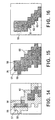
- FIG. 14 shows part of a typical horizontal edge image Sh, using black to denote pixels with sharpness values exceeding T, and hatching to denote pixels exceeding U but not exceeding T.
- “exceeding” means having a positive edge sharpness value exceeding T (or U). Pixels with negative sharpness values are processed separately.
- Edge points in the horizontal edge image Sh tend to be organized into chains with a generally vertical orientation.
- FIG. 14 shows one such chain, running generally from the top left toward the bottom right.
- This edge is irregular in shape, however, and if detected by threshold T, the edge is fragmented into two parts. Such irregularities and fragmentation greatly impair the efficiency which which the edge image can be encoded.
- FIG. 15 shows the thickened version of this edge.
- the edge detector 52 constructs FIG. 15 from FIG. 14 by the following procedure.
- the edge detector searches for a pixel in the horizontal edge image Sh in FIG. 14 exceeding threshold T.
- the first such pixel is found, it is placed in the thickened edge image in FIG. 15 as the first pixel of the first layer of an edge.
- This first layer is then extended in the left and right directions by including any contiguous pixels having the same sign and exceeding threshold U. The extension continues as far in each direction as such contiguous pixels continue.
- pixel 56 is found first and pixels 57 and 58 are added to complete the first layer. If there were further pixels exceeding threshold U immediately to the left of pixel 57 or to the right of pixel 58, they would also be added in.
- the edge detector continues in this manner, extending the thickened edge downward by adding new layers as long as it can find a pixel exceeding threshold T immediately below the bottom layer so far, and enlarging each layer horizontally to include contiguous pixels exceeding threshold T, as well as pixels exceeding threshold U out to the limit extension distance.
- pixel 60 is not added to the thickened edge because it would extend two pixels beyond the preceding layer, and the extension limit is one pixel.
- the thickened edge is considered complete.
- the edge detector searches for another pixel exceeding threshold T in absolute value to start a new thickened edge, and thickens this edge in the same way. This entire procedure is repeated until no more pixels exceeding threshold T can be found.
- a similar procedure is then followed to process pixels having negative sharpness values exceeding -T and -U.
- limit extension distance in the example above was one pixel, other limit extension distances such as zero, two, or three pixels can be used.
- the preferable limit extension distance depends in part on the threshold values T and U.
- FIG. 16 shows the trimmed version of the thickened edge in FIG. 15.
- the trimmed edge is constructed by comparing adjacent layers in the thickened edge, and trimming the longer layer to match the length of the shorter layer.
- pixel 59 is trimmed to reduce the length of its layer to three pixels, matching the length of the layer above. This trimming procedure is carried out from the top of the edge to the bottom, then repeated until all layers in the edge have been trimmed to the same length.
- the edge detector 52 examines the preceding layer, and trims in such a way as to maintain a constant offset from one layer to the next. In FIG. 16, for example, after trimming layers 61 and 62, the edge detector 52 trims layer 63 so that it is offset one pixel to the right of layer 62, because layer 62 is similarly offset one pixel to the right of layer 61.
- the trimmed edge in FIG. 16 is continuous, and has a more regular shape than the original edge in FIG. 14. These properties enable the edge in FIG. 16 to be encoded more efficiently than the edge in FIG. 14, even though it contains more pixels.
- the position of the rest of the edge can be specified just by giving the offset of each layer from the preceding layer.
- pixels exceeding threshold U but not threshold T can be quantized to zero but then dequantized to a non-zero value in the digital image decoder.
- edges are thickened and trimmed by a similar procedure, except that the thickening and trimming are done vertically, and the edge detector 52 works from left to right instead of from top to bottom.
- Edges in the diagonal edge image Sc can be processed either horizontally or vertically. The choice depends on the way in which the diagonal edge image will be encoded. If vertical chain encoding is used, for example, the thickening and trimming should be done horizontally.
- Edge thickening and trimming can also be added to the edge detection process in the first and second embodiments, and in any of the embodiments that follow.
- the invented edge thickening and trimming technique is moreover useful for regularizing edges in image encoding and image processing in general, and is not limited to edges detected by the difference-of-differences method.
- the fifth embodiment is similar to the second embodiment, but is adapted to process moving images comprising successive frames.
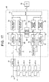
- the digital image encoder of the fifth embodiment has the same two-dimensional smoothing and down-sampling section 41 and edge detector 21 as in the second embodiment, but a different encoding section 65.
- the encoding section 65 comprises a pair of motion estimators 66 and 67, a motion vector encoder 68, a pair of motion compensators 69 and 70, and a pair of memories 71 and 72. It also has the same edge image encoder 24 and reduced image encoder 25 as in the digital image encoders of the preceding embodiments, and the same edge image decoder 31 and reduced image decoder 32 as in the digital image decoders of the preceding embodiments.
- Motion estimator 66 receives the pair of edge images Sh and Sv from the edge detector 21. To simplify the drawing, this pair of edge images is denoted by the single letter S. Motion estimator 66 also receives a pair of previous edge images S" (a previous horizontal edge image and a previous vertical edge image) from memory 71. Motion estimator 66 outputs edge motion vectors Ms and a pair of horizontal and vertical edge difference images, denoted for simplicity by the single symbol Ds.
- Motion estimator 67 receives the reduced image X n from the last smoothing filter 42-n and a previous reduced image X" n from memory 72, and outputs reduced motion vectors Mr and a reduced difference image Dr.
- the motion vector encoder 68 encodes motion vectors Ms and Mr and outputs motion information Cm.
- the edge image encoder 24 encodes the edge difference images Ds and outputs edge image information Cs. This information is decoded by the edge image decoder 31 to produce a pair of decoded edge difference images, which are denoted in the drawing by the single symbol D's.
- Motion compensator 69 receives this pair of images D's, the previous pair of images S", and the motion vectors Ms, and produces a pair of decoded edge images S 1 , which it stores in memory 71.
- the reduced image encoder 25 encodes the reduced difference image Dr and outputs reduced image information Cr.
- the reduced image decoder 32 decodes Cr and outputs a decoded reduced difference image D'r.
- Motion compensator 70 receives this image D'r, the previous reduced image X"n, and the motion vectors Mr, and produces a decoded reduced image X'n which it stores in memory 72.
- the multiplexer 73 multiplexes the edge image information Cs, motion information Cm, and reduced image information Cr for output as an encoded image C.
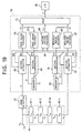
- the digital image decoder of the fifth embodiment has a decoding section 75 comprising a demultiplexer 76, a motion vector decoder 77, and decoders 31 and 32, motion compensators 69 and 70, and memories 71 and 72 identical to those in the digital image encoder in FIG. 17.
- the demultiplexer 76 receives the encoded image C from the input/output device 28 and demultiplexes it into edge image information Cs, motion information Cm, and reduced image information Cr.
- the motion vector decoder 77 decodes Cm to obtain decoded edge motion vectors M's and reduced motion vectors M'r.
- S m representing the pair of edge images Sh m and Sv m
- Y m the pair of high-frequency images Yh m and Yv m .
- motion estimator 67 estimates motion in the reduced image X n by, for example, the well-known block-matching method. This method involves comparing a block of pixels in the image X n with blocks displaced by k pixels horizontally and 1 pixels vertically from this block in the previous image X" n in memory 72, and selecting the vector (k, 1) that gives the closest match. These vectors (k, 1) are output as motion vectors Mr, while the differences between the pixel values in X n and the pixels values in X" n at positions offset by these motion vectors (k, 1) are output as the reduced difference image Dr.
- the reduced difference image Dr is the difference between X n and X" n over and above the motion represented by the motion vectors Mr.
- Motion estimator 66 carries out a similar process separately on the horizontal and vertical edge images to obtain the motion vectors Ms and the pair of edge difference images denoted Ds.
- the motion vector encoder 68 encodes the motion vectors Ms and Mr by a lossless encoding method such as a variable-length encoding method.
- the encoders 24 and 25 encode the difference images Ds and Dr by, for example, the same methods as used in the preceding embodiments.
- the decoders 31 and 32 employ methods reverse to those methods to obtain the decoded difference images D'r and D's.
- Motion compensator 70 adds the decoded reduced difference image D'r to the previous reduced image X" n according to the motion vectors Mr, and stores the resulting image X' n in memory 72.
- "According to the motion vectors Mr" means that each pixel value in D'r is added to a corresponding pixel value in the previous reduced image X" n at a location offset by a motion vector (k, 1) in Mr.
- the method by which X' n is obtained from D'r is inverse to the method by which Dr is obtained from X n , and the operations of encoder 25 and decoder 32 are mutually inverse, so image X' n is substantially identical to image X n .
- motion compensator 69 adds the two decoded edge difference images to the corresponding previous edge images according to the motion vectors Ms, and stores the resulting pair of decoded edge images S 1 in memory 71.
- the pair of edge images S 1 are substantially identical to the pair of edge images S output by the edge detector 21.
- Memory 72 has space for storing at least two complete reduced images: the previous image X" n supplied to motion estimator 67 and motion compensator 70, and the new image X' n stored by motion compensator 70. At the end of each frame, the previous image X" n is discarded, leaving the new image X' n to be used as the previous image in the next frame. Memory 71 stores edge images in a similar fashion.
- the motion estimators 66 and 67 may ignore the previous images S" and X" n in the memories 71 and 72 and supply the edge images S and reduced image X n directly to the encoders 24 and 25, instead of supplying difference images.
- the motion information Cm in this case consists of a message indicating that the current frame does not require motion compensation.
- the motion compensators 69 and 70 then simply output the images received from the decoders 31 and 32.
- the motion compensators 69 and 70 and memories 71 and 72 in the digital image decoder operate in the same way as the motion compensators 69 and 70 and memories 71 and 72 in the digital image encoder, using the decoded motion vectors M's and M'r supplied by the motion vector decoder 77. Since a lossless encoding scheme is employed for the motion vectors, M's and M'r are exactly identical to Ms and Mr, and the images denoted S 1 and X' n in FIG. 18 are exactly identical to the images denoted S 1 and X' n in FIG. 17. Further operation of the digital image decoder is as already described in the second embodiment.
- One advantage of the fifth embodiment is that most of the block matching is performed in the edge images, which have been thresholded and tend to consist mostly of zero-valued pixels.
- the large number of zero-valued pixels greatly speeds up the block-matching process. Further gains in speed are possible by using motion vectors calculated for one of the two edge images to help find motion vectors in the other edge image.
- Another advantage is that the motion estimators and compensators in the digital image encoder and digital image decoder use identical previous images S" and X" n . This prevents the accumulation of quantization error and other image errors resulting from compressive coding in the encoders 24 and 25, and ensures consistency between motion estimation in the digital image encoder and motion compensation in the digital image decoder.
- the fifth embodiment can be employed in video teleconferencing and a wide variety of other multimedia applications.
- the sixth embodiment is similar to the fifth embodiment, with further provisions for speeding up the computation of motion vectors.
- the encoding section 78 of the digital image encoder in the sixth embodiment is similar to the encoding section 65 in the fifth embodiment, but has a bidirectional interconnection 79 between motion estimators 66 and 67.
- This enables motion estimator 67 to receive the edge motion vectors Ms found by motion estimator 66, scale them down to the size of the low-frequency reduced image X n , and restrict the search for motion vectors in image X n to vectors close to the scaled-down edge motion vectors.
- the search can be eliminated entirely: the reduced motion vectors Mr can be computed directly from the edge motion vectors Ms.
- motion estimator 66 can receive the motion vectors Mr found by block matching in the low-frequency reduced image X n , scale them up to the size of the edge images Sh and Sv, and restrict the search for motion vectors in Sh and Sv to vectors close to the scaled-up vectors. This scheme is particularly effective in detecting large, rapid motion.
- the sixth embodiment has the same structure as the fifth embodiment and operates in the same way, so further description will be omitted.
- the sixth embodiment enables frames to be encoded at a faster rate than in the fifth embodiment.
- the seventh embodiment combines features of the third and fifth embodiments by detecting edges horizontally, vertically, and diagonally, and employing motion compensation.
- the digital image encoder of the seventh embodiment has the same two-dimensional smoothing and down-sampling section 41, one-dimensional smoothing and down-sampling section 51, and edge detector 52 as in the third embodiment (FIG. 8), and the same encoding section 65 as in the fifth embodiment (FIG. 17).
- the symbol S in FIG. 20 denotes the set of three edge images Sv, Sh, and Sc in FIG. 8.
- Each of the symbols S 1 , S", Ds, and D's likewise denotes a set of three edge images.
- the digital image decoder of the seventh embodiment has the same decoding section 75 as the fifth embodiment (FIG. 17), and the same two-dimensional smoothing and down-sampling filters 53-1 to 53-(n - 1), edge synthesizers 54-1 to 54-n, and inverse wavelet transform processor 55 as in the third embodiment (FIG. 11).
- the seventh embodiment operates as explained in the third and fifth embodiments, and provides similar effects, so further description will be omitted.
- the eighth embodiment combines features of the sixth and seventh embodiments.
- the digital image encoder of the eighth embodiment has the same configuration as in the seventh embodiment (FIG. 20), except for the addition of a bidirectional interconnection 79 between motion estimators 66 and 67 as in the sixth embodiment (FIG. 19).
- the eighth embodiment operates as explained in the sixth and seventh embodiments, so further description will be omitted.
- the ninth embodiment performs motion estimation before edge detection, smoothing, and down sampling.
- the encoder performs substantially all the processes carried out in the decoder, including edge synthesis and the inverse wavelet transform.
- the original image frames input at the input terminal 10 are supplied to a motion estimator 80, which performs motion estimation as described above, outputting a difference image D 0 and motion vectors M.
- the motion vectors M are encoded by a motion vector encoder 68 as in the fifth to eighth embodiments.
- the difference image D 0 is supplied to an edge detector 21 and two-dimensional smoothing and down-sampling section 41 in place of the original image X 0 , and is processed in the same way that the original image X 0 was processed in the second embodiment.
- the resulting pair of edge images will again be denoted by the symbol S, while the reduced image resulting from smoothing and down-sampling of D 0 will be denoted D n .
- These images S and D n are encoded by respective encoders 24 and 25 to produce encoded image information Cs and Cr, which is combined with the motion information Cm by a multiplexer 73 as in the preceding embodiments.
- the motion compensator 81 uses this image D' 0 , the motion vectors M output by the motion estimator 80, and a previous image X" 0 stored in a memory 82, the motion compensator 81 produces a new reconstructed image X' 0 , which is stored in the memory 82.
- the previous image X" 0 was also supplied to the motion estimator 80 for use in motion estimation.
- the reconstructed image X' 0 will become the previous image in the next frame.
- the motion estimator 80, motion compensator 81, and memory 82 in FIG. 23 operate like the motion estimator 67, motion compensator 70, and memory 72 in the fifth or seventh embodiment (FIG. 17 or 20), although they operate on the original image X 0 instead of the reduced image X n .
- the encoding section 83 in the ninth embodiment comprises the motion vector encoder 68, edge image encoder 24, reduced image encoder 25, and multiplexer 73.
- the digital image decoder of the ninth embodiment has a decoding section 84 with a demultiplexer 76 and motion vector decoder 77 similar to those in the fifth to eighth embodiments.
- the other elements in FIG. 24 are similar to the elements with the same reference numerals in FIG. 23.
- the motion compensator 81 receives a fully reconstructed difference image D' 0 from the inverse wavelet transform processor 50, and outputs a fully reconstructed image X' 0 to the input/output device 37.
- the digital image encoder in FIG. 23 and digital image decoder in FIG. 24 operate with identical previous images X" 0 , thereby maintaining consistency between motion estimation in the encoder and decoder. Performing motion estimation before edge detection can lead to higher compression ratios than in the fifth to eighth embodiments, because only one set of motion vectors has to be encoded.
- the tenth embodiment combines features of the third and ninth embodiments.
- Three edge images are detected, as in the third embodiment.
- Edge detection, smoothing, and downsampling are preceded by motion estimation, and followed by all the processes performed in the digital image decoder, as in the ninth embodiment.
- the digital image encoder of the tenth embodiment has the motion estimator 80, motion compensator 81, memory 82, and encoding section 83 of the ninth embodiment (FIG. 23), and other elements as in the third embodiment (FIGs. 9 and 11).
- the digital image decoder has the decoding section 84, motion compensator 81, and memory 82 of the ninth embodiment (FIG. 24), and other elements as in the third embodiment (FIG. 11).
- the tenth embodiment operates as described in the third and ninth embodiments, and provides similar advantages. A detailed description will be omitted.
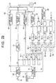
- the eleventh embodiment is a digital image encoder/decoder (codec) that combines the functions of the digital image encoder and decoder of the ninth embodiment.
- codec digital image encoder/decoder
- the eleventh embodiment thus provides one device that can operate in either an encoding state or a decoding state.
- the eleventh embodiment adds the demultiplexer 76 and motion vector decoder 77 of the digital image decoder of the ninth embodiment (FIG. 24), a second input terminal 90, and three switches 91, 92, and 93.
- switches 91, 92, and 93 are set to the position marked "a" in the drawing.
- Successive frames X 0 are input at input terminal 10 and processed just as in the digital image encoder of the ninth embodiment, the encoded results being output from the demultiplexer 73 to input/output device 28.
- switches 91, 92, and 93 are set to the position marked "b."
- the encoded moving image C is input from the second input terminal 90 to the demultiplexer 76 and processed just as in the digital image decoder of the ninth embodiment, the decoded results being output from the motion compensator 81 to input/output device 37.
- the eleventh embodiment has the same advantages as the ninth embodiment, with the further advantage of allowing the encoding and decoding functions to share the same motion compensator 81, decoders 31 and 32, filters 48-m, edge synthesizers 49-m, and inverse wavelet transform processor 50, thereby avoiding needless duplication.
- This embodiment is particularly suited for videophones and other bidirectional video systems.
- the twelfth embodiment is a digital image encoder/decoder that combines the features of the tenth and eleventh embodiments.
- the twelfth embodiment adds to the digital image encoder of the tenth embodiment (FIG. 25) the same demultiplexer 76, motion vector decoder 77, second input terminal 90, and switches 91, 92, and 93 as in the eleventh embodiment.
- the twelfth embodiment operates like the eleventh, but has the further advantage of improved rendition of high-frequency image detail due to diagonal edge detection.
- the invented encoding and decoding method and devices provide high compression rates with modest amounts of computation. Although there is some loss of detail, reconstructed images are not distorted, and because high-frequency information is synthesized in a single step instead of by iteration, the reconstruction process is reliably completed within a short and definite time.
- the invention can be usefully applied to both still and moving images for a wide variety of purposes, in a wide variety of systems.
- sgn denotes the algebraic sign (plus or minus one), and arctan the inverse tangent function.
- the encoding section then has only one set of edge positions to encode.
- the decoding section in the digital image decoder can recover Sh(i, j) and Sv(i, j) from S(i, j) and ⁇ (i, j).
- This method of encoding only a single edge image is particularly effective if chain encoding is employed. Because the direction angle tends to change only slowly along a chain of edge points. Moreover, the angle tends to be perpendicular to the direction of the chain, so it is possible to have the edge detector calculate only the above edge sharpness S(i, j), and let the decoder infer the direction angle ⁇ (i, j) of an edge point (i, j) from the direction of the chain in the vicinity of that point.
- the compression ratio can be significantly improved in this way, although with some loss of reconstruction accuracy.
- This encoding method can also be applied to the horizontal and vertical edge images in the other embodiments, if the original image is not down-sampled before horizontal and vertical edge detection. The necessary down-sampling is then performed instead in the decoder, as in the second embodiment.
- this encoding method has the further advantage of reducing the number of edge images for which motion vectors have to be computed.
- the two-dimensional smoothing performed in a single step, instead of by a cascaded series of filters.
- the filters h 1 , h 2 , ..., h n in the first embodiment can be mutually convolved to yield a single filter that gives the same result as applying the cascaded series of filters.
- down-sampling can be incorporated into this single filter simply by calculating the values of only 1/4 n of the output pixels.
- the smoothing filters applied in the horizontal and vertical directions need not be identical.
- a smoothing filter with an even number of taps can be applied in one of these directions, and a smoothing filter with an odd number of taps in the other direction.
- the edge synthesis filters (e), completion filters (f), and high-pass filters (g) employed for decoding then also require separate versions for the horizontal and vertical directions.
- Edge detection is not limited to the difference-of-differences method. This method is preferred, but other methods can be employed.
- the filters employed were described as being symmetric around zero or 1/2, but this is only a matter of notation.
- the center of symmetry can be disposed at any convenient location.
- the standard edge from which the edge synthesis filters are generated need not be an edge of the type shown in FIG. 3, in which pixel values change at first one constant rate, then another constant rate. Other types can be used, provided the standard edge has only one point which would be detected as an edge point by the edge detector.
Landscapes
- Engineering & Computer Science (AREA)
- Multimedia (AREA)
- Signal Processing (AREA)
- Compression Or Coding Systems Of Tv Signals (AREA)
- Image Processing (AREA)
- Compression Of Band Width Or Redundancy In Fax (AREA)
Claims (62)
- Verfahren zum Codieren und Decodieren eines digitalisierten Bildes, das aus Pixeln mit Pixelwerten (X0 (i, j)) besteht, mit den folgenden Verfahrensschritten:die Schärfe von Kanten in dem digitalisierten Bild festzustellen und den Pixeln entsprechende Schärfewerte (Sh(i, j), Sv(i, j)) zuzuordnen;Positions- (i, j) und Schärfewerte (Sh, Sv) von Pixeln zu codieren (24), deren Schärfewerte eine bestimmte Schwelle (T) übersteigen, um Kantenbildinformation (Cs) zu erzeugen;das digitalisierte Bild unter Verwendung einer Kaskadenreihe von zweidimensionalen Glättungs- (22-m, m = 1, ..., n) und Herunterabtastfiltem (42-m, m = 1, ..., n) wiederholt zu filtern (43, 45) und herunterabzutasten (44, 46), um ein Reduktionsbild (Xn) zu erzeugen;das Reduktionsbild zu codieren (25), um Reduktionsbildinformation (Cr) zu erzeugen; die Kantenbildinformation (Cs) und die Reduktionsbildinformation (Cr) an eine Eingabe-/Ausgabevorrichtung (28) zu senden;die Kantenbildinformation und die Reduktionsbildinformation von der Eingabe-/Ausgabevorrichtung (28) zu empfangen;aus der von der Eingabe-/Ausgabevorrichtung (28) empfangenen Kantenbildinformation einen ersten Satz decodierte Kantenbilder zu erzeugen (31), der mindestens ein erstes decodiertes horizontales Kantenbild (Sh1) und ein erstes decodiertes vertikales Kantenbild (Sv1) enthält;den ersten Satz decodierte Kantenbilder unter Verwendung mindestens eines zweidimensionalen Glättungsfilters (33-1, 48-1, 53-1) zu filtern (33-(m-1), m = 2, ..., n) und herunterabzutasten (48-(m-1), 53-(m-1), m = 2, ... n), um eine Reihe von Sätzen decodierte Kantenbilder (Shm, Svm, m = 1, ..., n) zu erzeugen, die den ersten Satz decodierte Kantenbilder (Sh1, Sv1) enthält;eine Reihe von Sätzen Hochfrequenzbilder (Yhm, Yvm, m = 1, ..., n) durch Synthese herzustellen, indem die Reihe von Sätzen decodierte Kantenbilder mit jeweiligen Kantensynthesefiltern (34-m, 49-m, 54-m, m = 1, ..., n) gefiltert wird;die von der Eingabe-/Ausgabevorrichtung (28) empfangene Reduktionsbildinformation (Cr) zu decodieren (32), um ein decodiertes Reduktionsbild (X'n) zu erhalten; undeine Wavelet-Rücktransformation (36-m, 50-m, 55-m, m = 1, ... n) an dem decodierten Reduktionsbild und der Reihe von Sätzen Hochfrequenzbilder durchzuführen, um ein decodiertes digitalisiertes Bild (X'0) zu erhalten.
- Verfahren nach Anspruch 1, bei dem alle Hochfrequenzbilder die gleiche Größe haben, mit dem weiteren Verfahrensschritt, das decodierte Reduktionsbild auf diese Größe heraufabzutasten, bevor die Wavelet-Rücktransformation durchgeführt wird.
- Verfahren nach Anspruch 1, bei demder Verfahrensschritt, den ersten Satz decodierte Kantenbilder zu filtern, außerdem Herunterabtasten umfasst, so dass die Sätze decodierte Kantenbilder in der Reihe von Sätzen decodierte Kantenbilder zunehmend geringere Größen haben, undder Verfahrensschritt, eine Wavelet-Rücktransformation durchzuführen, Heraufabtasten durch Einfügen von Pixeln mit dem Wert Null umfasst.
- Verfahren nach Anspruch 3, bei dem zum Filtern aller Sätze decodierte Kantenbilder identische Kantensynthesefilter verwendet werden.
- Verfahren nach Anspruch 1, bei dem jedes Kantensynthesefilter Koeffizienten hat, die durch Filtern einer Standardkante mit einem Hochpassfilter erzeugt werden.
- Verfahren nach Anspruch 5, bei dem die Standardkante aus einem ersten Teil und einem zweiten Teil besteht, mit Pixelwerten, die sich in dem ersten Teil mit einer konstanten Rate ändern und in dem zweiten Teil mit einer anderen konstanten Rate ändern.
- Verfahren nach Anspruch 5, bei dem das zur Erzeugung mindestens eines der Kantensynthesefilter verwendete Hochpassfilter gerade Symmetrie hat.
- Verfahren nach Anspruch 5, bei dem das zur Erzeugung mindestens eines der Kantensynthesefilter verwendete Hochpassfilter ungerade Symmetrie hat.
- Verfahren nach Anspruch 8, bei dem der Verfahrensschritt der Herstellung durch Synthese folgendes umfasst:Differenzen zwischen aufeinander folgenden Koeffizienten des einen Kantensynthesefilters zu nehmen, um ein Differenz-Kantensynthesefilter zu erzeugen;eines der decodierten Kantenbilder mit dem Differenz-Kantensynthesefilter zu filtern, um ein Differenz-Hochfrequenzbild zu erzeugen; undin dem Differenz-Hochfrequenzbild Werte anzusammeln.
- Verfahren nach Anspruch 5, bei dem der Verfahrensschritt, eine Wavelet-Rücktransformation durchzuführen, umfasst, mindestens eines der Hochfrequenzbilder mit einem konjugierten Filter des Hochpassfilters zu filtern.
- Verfahren nach Anspruch 1, bei dem das Nachweisen der Schärfe von Kanten folgendes umfasst:Differenzen zwischen Pixelwerten benachbarter Pixel zu nehmen; undDifferenzen der Differenzen zu nehmen.
- Verfahren nach Anspruch 11, bei dem das Nachweisen der Schärfe von Kanten die folgenden unabhängig durchgeführten Verfahrensschritte umfasst:die Differenzen und die Differenzen der Differenzen in einer horizontalen Richtung zu nehmen, um ein horizontales Kantenbild zu erhalten; unddie Differenzen und die Differenzen der Differenzen in einer vertikalen Richtung zu nehmen, um ein vertikales Kantenbild zu erhalten.
- Verfahren nach Anspruch 12, bei dem jeder Satz decodierte Kantenbilder in der Reihe von Sätzen decodierte Kantenbilder ein decodiertes horizontales Kantenbild und ein decodiertes vertikales Kantenbild umfasst und bei dem der Verfahrensschritt der Herstellung durch Synthese folgendes umfasst:jedes decodierte horizontale Kantenbild horizontal zu filtern, um ein horizontales Hochfrequenzbild zu erhalten; undjedes decodierte vertikale Kantenbild vertikal zu filtern, um ein vertikales Hochfrequenzbild zu erhalten.
- Verfahren nach Anspruch 13, bei dem der Verfahrensschritt, eine Wavelet-Rücktransformation durchzuführen, folgendes umfasst:das Reduktionsbild horizontal und vertikal mit einem Tiefpassfilter zu filtern;das horizontale Hochfrequenzbild horizontal mit einem Hochpassfilter und vertikal mit einem Tiefpassfilter zu filtern; unddas vertikale Hochfrequenzbild vertikal mit einem Hochpassfilter und horizontal mit einem Tiefpassfilter zu filtern.
- Verfahren nach Anspruch 11, bei dem das Nachweisen der Schärfe von Kanten die folgenden unabhängig durchgeführten Verfahrensschritte umfasst:das digitalisierte Bild in einer vertikalen Richtung zu glätten und herunterabzutasten und dann die Differenzen und die Differenzen der Differenzen in einer horizontalen Richtung zu nehmen, um ein horizontales Kantenbild zu erhalten; unddas digitalisierte Bild in der horizontalen Richtung zu glätten und herunterabzutasten und dann die Differenzen und die Differenzen der Differenzen in der vertikalen Richtung zu nehmen, um ein vertikales Kantenbild zu erhalten; unddie Differenzen und die Differenzen der Differenzen in dem digitalisierten Bild aufeinander folgend in der horizontalen Richtung und der vertikalen Richtung zu nehmen, um ein diagonales Kantenbild zu erhalten.
- Verfahren nach Anspruch 15, bei dem jeder Satz decodierte Kantenbilder in der Reihe von Sätzen decodierte Kantenbilder ein decodiertes horizontales Kantenbild, ein decodiertes vertikales Kantenbild und ein decodiertes diagonales Kantenbild umfasst und bei dem der Verfahrensschritt der Herstellung durch Synthese folgendes umfasst:jedes decodierte horizontale Kantenbild horizontal zu filtern und herunterabzutasten, um ein entsprechendes horizontales Hochfrequenzbild zu erhalten;jedes decodierte vertikale Kantenbild vertikal zu filtern und herunterabzutasten, um ein entsprechendes vertikales Hochfrequenzbild zu erhalten; undjedes decodierte diagonale Kantenbild sowohl horizontal als auch vertikal zu filtern und herunterabzutasten, um ein entsprechendes diagonales Hochfrequenzbild zu erhalten.
- Verfahren nach Anspruch 16, bei dem der Verfahrensschritt, eine Wavelet-Rücktransformation durchzuführen, folgendes umfasst:das Reduktionsbild horizontal und vertikal mit einem Tiefpassfilter zu filtern;das horizontale Hochfrequenzbild horizontal mit einem Hochpassfilter und vertikal mit einem Tiefpassfilter zu filtern;das vertikale Hochfrequenzbild vertikal mit einem Hochpassfilter und horizontal mit einem Tiefpassfilter zu filtern; unddas diagonale Hochfrequenzbild horizontal und vertikal mit einem Hochpassfilter zu filtern.
- Verfahren nach Anspruch 1, das auf aufeinander folgende Einzelbilder eines Bewegtbildes angewandt wird, wobei das Codieren von Positions- und Schärfewerten folgendes umfasst:mindestens ein Kantenbild zu erzeugen, das Pixel mit Schärfewerten enthält;ein erstes vorhergehendes Kantenbild, das zu einem vorhergehenden Einzelbild gehört, aus einem ersten Speicher (71) zu lesen;Kantenbewegungsvektoren zu erzeugen, indem eine Bewegung des Kantenbildes in Bezug auf das erste vorhergehende Kantenbild nachgewiesen wird;die Kantenbewegungsvektoren zu codieren, um Kantenbewegungsinformation als Teil der Kantenbildinformation zu erzeugen;ein Kantendifferenzbild zu erzeugen, indem Differenzen zwischen dem Kantenbild und dem ersten vorhergehenden Kantenbild zusätzlich zu der Bewegung des Kantenbildes nachgewiesen werden; unddas Kantendifferenzbild zu codieren, um Kantendifferenzinformation als ein anderer Teil der Kantenbildinformation zu erzeugen.
- Verfahren nach Anspruch 18, bei dem das Codieren von Positions- und Schärfewerten außerdem folgendes umfasst:die Kantendifferenzinformation zu decodieren, um ein erstes decodiertes Kantendifferenzbild zu erzeugen;das erste decodierte Kantendifferenzbild im Übereinstimmung mit den Kantenbewegungsvektoren zu dem ersten vorhergehenden Kantenbild zu addieren, um ein erstes neues Kantenbild zu erzeugen; unddas erste neue Kantenbild in dem ersten Speicher (71) zu speichern, zur Verwendung als ein erstes vorhergehendes Kantenbild in einem nachfolgenden Einzelbild.
- Verfahren nach Anspruch 18, bei dem das Erzeugen eines ersten Satzes Kantenbilder aus der Kantenbildinformation folgendes umfasst:die von der Eingabe-/Ausgabevorrichtung (28) empfangene Kantenbildinformation zu decodieren, um decodierte Kantenbewegungsvektoren, die mit den Kantenbewegungsvektoren identisch sind, und ein zweites decodiertes Kantendifferenzbild zu erhalten, das mit dem ersten decodierten Kantendifferenzbild identisch ist;ein zweites vorhergehendes Kantendifferenzbild aus einem zweiten Speicher (71) zu lesen;das zweite decodierte Kantendifferenzbild in Übereinstimmung mit den decodierten Kantenbewegungsvektoren zu dem zweiten vorhergehenden Kantenbild zu addieren, um ein zweites neues Kantenbild zu erzeugen; unddas zweite neue Kantenbild in dem zweiten Speicher (71) zu speichern, zur Verwendung als ein zweites vorhergehendes Kantenbild in einem nachfolgenden Einzelbild.
- Verfahren nach Anspruch 18, bei dem das Codieren des Reduktionsbildes folgendes umfasst:ein erstes vorhergehendes Reduktionsbild, das zu dem vorhergehenden Einzelbild gehört, aus einem dritten Speicher (72) zu lesen;Reduktionsbewegungsvektoren zu erzeugen, indem eine Bewegung des Reduktionsbildes in Bezug auf das vorhergehende Reduktionsbild nachgewiesen wird;die Reduktionsbewegungsvektoren zu codieren, um Reduktionsbewegungsinformation als Teil der Reduktionsbildinformation zu erzeugen;ein Reduktionsdifferenzbild zu erzeugen, indem Differenzen zwischen dem Reduktionsbild und dem ersten vorhergehenden Reduktionsbild zusätzlich zu der Bewegung des Reduktionsbildes nachgewiesen werden; unddas Reduktionsdifferenzbild zu codieren, um Reduktionsdifferenzinformation als ein anderer Teil der Reduktionsbildinformation zu erzeugen.
- Verfahren nach Anspruch 21, bei dem das Codieren des Reduktionsbildes weiterhin folgendes umfasst:die Reduktionsdifferenzinformation zu decodieren, um ein erstes decodiertes Reduktionsdifferenzbild zu erzeugen;das erste decodierte Reduktionsdifferenzbild in Übereinstimmung mit den Reduktionsbewegungsvektoren zu dem ersten vorhergehenden Reduktionsbild zu addieren, um ein erstes neues Reduktionsbild zu erzeugen; unddas erste neue Reduktionsbild in dem dritten Speicher (72) zu speichern, zur Verwendung als ein erstes vorhergehendes Reduktionsbild in einem nachfolgenden Einzelbild.
- Verfahren nach Anspruch 21, bei dem das Decodieren der von der Eingabe-/Ausgabevorrichtung (28) empfangenen Reduktionsbildinformation folgendes umfasst:die Reduktionsbildinformation zu decodieren, um decodierte Reduktionsbewegungsvektoren, die mit den Reduktionsbewegungsvektoren identisch sind, und ein zweites decodiertes Reduktionsdifferenzbild zu erhalten, das mit dem ersten decodierten Reduktionsdifferenzbild identisch ist;ein zweites vorhergehendes Reduktionsdifferenzbild aus einem vierten Speicher (72) zu lesen;das zweite decodierte Reduktionsdifferenzbild in Übereinstimmung mit den Reduktionsbewegungsvektoren zu dem zweiten vorhergehenden Reduktionsbild zu addieren, um ein zweites neues Reduktionsbild zu erzeugen; unddas zweite neue Reduktionsbild in dem vierten Speicher (71) zu speichern, zur Verwendung als ein zweites vorhergehendes Reduktionsbild in einem nachfolgenden Einzelbild.
- Verfahren nach Anspruch 21, bei dem das Erzeugen von Kantenbewegungsvektoren umfasst, die Reduktionsbewegungsvektoren zu verwenden, um einen Suchbereich für die Kantenbewegungsvektoren auszuwählen.
- Verfahren nach Anspruch 21, bei dem das Erzeugen von Reduktionsbewegungsvektoren umfasst, die Kantenbewegungsvektoren zu verwenden, um einen Suchbereich für die Reduktionsbewegungsvektoren auszuwählen.
- Verfahren nach Anspruch 1, das auf aufeinander folgende Einzelbilder eines Bewegtbildes angewandt wird, mit folgenden weiteren Verfahrensschritten:ein aktuelles Einzelbild des Bewegtbildes zu empfangen;ein erstes vorhergehendes decodiertes Einzelbild des Bewegtbildes aus einem fünften Speicher (82) zu lesen;Bewegungsvektoren zu erzeugen, indem eine Bewegung des aktuellen Einzelbildes in Bezug auf das erste vorhergehende decodierte Einzelbild nachgewiesen wird;die Bewegungsvektoren zu codieren, um Bewegungsinformation zu erzeugen;das digitalisierte Bild zu erzeugen, indem Differenzen zwischen dem aktuellen Einzelbild und dem ersten vorhergehenden decodierten Einzelbild zusätzlich zu der Bewegung des aktuellen Bildes nachgewiesen werden; unddie Bewegungsinformation an die Eingabe-/Ausgabevorrichtung (28) zu senden.
- Verfahren nach Anspruch 26, mit folgenden weiteren Verfahrensschritten:die Bewegungsinformation von der Eingabe-/Ausgabevorrichtung (28) zu empfangen;die Bewegungsinformation zu codieren, um decodierte Bewegungsvektoren zu erhalten; ein zweites vorhergehendes decodiertes Einzelbild aus einem sechsten Speicher (82) zu lesen;das decodierte digitalisierte Bild in Übereinstimmung mit den decodierten Bewegungsvektoren zu dem zweiten vorhergehenden decodierten Einzelbild zu addieren, um ein neues decodiertes Einzelbild zu erzeugen; unddas neue decodierte Einzelbild in dem sechsten Speicher (82) zu speichern, zur nachfolgenden Verwendung als ein zweites vorhergehendes decodiertes Einzelbild.
- Verfahren nach Anspruch 27, mit folgenden weiteren Verfahrensschritten:aus der an die Eingabe-/Ausgabevorrichtung (28) gesendeten Kantenbildinformation einen zweiten Satz Kantenbilder zu erzeugen, der mit dem ersten Satz Kantenbilder identisch ist;den zweiten Satz Kantenbilder unter Verwendung mindestens eines zweidimensionalen Tiefpassfilters zu filtern, um eine zweite Reihe von Sätzen Kantenbilder zu erzeugen, die den zweiten Satz Kantenbilder enthält;eine zweite Reihe von Sätzen Hochfrequenzbilder durch Synthese herzustellen, indem die zweite Reihe von Sätzen Kantenbilder mit jeweiligen Kantensynthesefiltern gefiltert wird;die an die Eingabe-/Ausgabevorrichtung (28) gesendete Reduktionsbildinformation zu decodieren, um ein zweites decodiertes Reduktionsbild zu erhalten;eine Wavelet-Rücktransformation an dem zweiten decodierten Reduktionsbild und der zweiten Reihe von Sätzen Hochfrequenzbilder durchzuführen, um ein zweites decodiertes digitalisiertes Bild zu erhalten;das zweite decodierte digitalisierte Bild in Übereinstimmung mit den Bewegungsvektoren zu dem ersten vorhergehenden decodierten Einzelbild zu addieren, um ein neues decodiertes Einzelbild zu erzeugen, unddas neue decodierte Einzelbild in dem fünften Speicher (82) zu speichern, zur nachfolgenden Verwendung als ein erstes vorhergehendes decodiertes Einzelbild.
- Digitalbildcodierer zum Codieren eines digitalisierten Bildes, das aus Pixeln mit Pixelwerten (X0 (i, j)) besteht, der folgendes enthält:einen Eingangsanschluss (10) zum Empfang des digitalisierten Bildes;eine Kaskadenreihe von zweidimensionalen Glättungs- (22-m, m = 1, ..., n) und Herunterabtastfiltern (42-m, m = 1, ..., n) zum wiederholten Filtern und Herunterabtasten des digitalisierten Bildes, um eine Reihe von gefilterten und herunterabgetasteten Bildern (Xm, m = 1, ..., n) zu erzeugen, die in einem Reduktionsbild (Xn) gipfeln;einen Codierteil (25, 27, 65, 78, 83), der mit der Kaskadenreihe verbunden ist, zum Codieren des Reduktionsbildes, um Reduktionsbildinformation (Cr) zu erzeugen;einen Kantendetektor (21, 52) der mit dem Eingangsanschluss (10) verbunden ist, zur Erzeugung von mindestens einem Kantenbild (Sh, Sv) durch Nachweis von und Schwellwertoperation (T) an Kantenschärfewerten (Sh(i, j), Sv(i, j)) in dem digitalisierten Bild; undeinen Kantencodierteil (24, 27, 65, 78, 83), der mit dem Kantendetektor (21, 52) verbunden ist, zum Codieren des Kantenbildes, um Kantenbildinformation (Cs) zu erzeugen.
- Digitalbildcodierer nach Anspruch 29, bei dem der Kantendetektor (21, 52) Veränderungen in der Änderungsrate der Pixelwerte von Pixel zu Pixel nachweist.
- Digitalbildcodierer nach Anspruch 30, bei dem der Kantendetektor (21) die Veränderungen horizontal in dem digitalisierten Bild nachweist, um ein horizontales Kantenbild zu erzeugen, und die Veränderungen vertikal in dem digitalisierten Bild nachweist, um ein vertikales Kantenbild zu erzeugen.
- Digitalbildcodierer nach Anspruch 30, mit einem eindimensionalen Glättungs- und Herunterabtastteil (51), der zwischen dem Eingangsanschluss (10) und dem Kantendetektor (52) angeordnet ist, zum Glätten und Herunterabtasten des digitalisierten Bildes horizontal, um ein horizontal herunterabgetastetes Bild zu erzeugen, und Glätten und Herunterabtasten des digitalisierten Bildes vertikal, um ein vertikal herunterabgetastetes Bild zu erzeugen.
- Digitalbildcodierer nach Anspruch 32, bei dem der Kantendetektor (52) die Veränderungen horizontal in dem vertikal herunterabgetasteten Bild nachweist, um ein horizontales Kantenbild zu erzeugen, die Veränderungen vertikal in dem horizontal herunterabgetasteten Bild nachweist, um ein vertikales Kantenbild zu erzeugen, und die Veränderungen horizontal und vertikal in dem digitalisierten Bild nachweist, um ein diagonales Kantenbild zu erzeugen.
- Digitalbildcodierer nach Anspruch 29, bei dem der Codierteil (27) folgendes enthält:einen Kantenbildcodierer (24), der mit dem Wähler (50) verbunden ist, zum Codieren des Kantenbildes, um Kantenbildinformation zu erzeugen;einen Reduktionsbildcodierer (25), der mit der Kaskadenreihe von zweidimensionalen Glättungs- und Herunterabtastfiltern (42-m) verbunden ist, zum Codieren des Reduktionsbildes, um Reduktionsbildinformation zu erzeugen; undeinen Multiplexer (26), der mit dem Kantenbildcodierer (24) und dem Reduktionsbildcodierer (25) verbunden ist, zum Multiplexen der Reduktionsbildinformation und der Kantenbildinformation.
- Digitalbildcodierer nach Anspruch 29, bei dem das digitalisierte Bild ein Einzelbild in einem Bewegtbild ist, das aus aufeinander folgenden Einzelbildern besteht, und der Codierteil (65, 78) folgendes enthält:einen ersten Speicher (71) zum Speichern eines vorhergehenden Kantenbildes, das zu einem vorhergehenden Einzelbild unter den Einzelbildern gehört;einen ersten Bewegungsschätzer (66), der mit dem Kantendetektor (21) und dem ersten Speicher (71) verbunden ist, zum Nachweis einer Bewegung des Kantenbildes in Bezug auf das vorhergehende Kantenbild, Erzeugen von Bewegungsvektoren, Nachweis von Differenzen zwischen dem Kantenbild und dem vorhergehenden Kantenbild zusätzlich zu der Bewegung des Kantenbildes, und Erzeugen eines Kantendifferenzbildes;einen zweiten Speicher (72) zum Speichern eines vorhergehenden Reduktionsbildes, das zu dem vorhergehenden Einzelbild gehört; undeinen zweiten Bewegungsschätzer (67), der mit der Kaskadenreihe von zweidimensionalen Glättungs- und Herunterabtastfiltern (42-m) und dem zweiten Speicher (72) verbunden ist, zum Nachweis einer Bewegung des Reduktionsbildes in Bezug auf das vorhergehende Reduktionsbild, Erzeugen von Reduktionsbewegungsvektoren, Nachweis von Differenzen zwischen dem Reduktionsbild und dem vorhergehenden Reduktionsbild zusätzlich zu der Bewegung des Reduktionsbildes, und Erzeugen eines Reduktionsdifferenzbildes.
- Digitalbildcodierer nach Anspruch 35, bei demder erste Bewegungsschätzer (66) mit dem zweiten Bewegungsschätzer (67) verbunden ist undder erste Bewegungsschätzer (66) die Reduktionsbewegungsvektoren verwendet, um einen Suchbereich für die Kantenbewegungsvektoren auszuwählen.
- Digitalbildcodierer nach Anspruch 35, bei demder erste Bewegungsschätzer (66) mit dem zweiten Bewegungsschätzer (67) verbunden ist undder zweite Bewegungsschätzer (67) die Kantenbewegungsvektoren verwendet, um einen Suchbereich für die Reduktionsbewegungsvektoren auszuwählen.
- Digitalbildcodierer nach Anspruch 35, bei dem der Codierteil (65, 78) folgendes enthält:einen Kantenbildcodierer (24), der mit dem ersten Bewegungsschätzer (66) verbunden ist, zum Codieren des Kantendifferenzbildes, um Kantenbildinformation zu erzeugen;einen Kantenbilddecodierer (31), der mit dem Kantenbildcodierer (24) verbunden ist, zum Decodieren der Kantenbildinformation, um ein decodiertes Kantendifferenzbild zu erzeugen;einen ersten Bewegungskompensator (69), der mit dem ersten Speicher (71), dem ersten Bewegungsschätzer (66) und dem Kantenbilddecodierer (31) verbunden ist, zum Addieren des decodierten Kantendifferenzbildes zu dem vorhergehenden Kantenbild in Übereinstimmung mit den Kantenbewegungsvektoren, um ein neues Kantenbild zu erzeugen, und Speichern des neues Kantenbildes in dem ersten Speicher (71), zur Verwendung als ein vorhergehendes Kantenbild in einem nachfolgenden Einzelbild unter den Einzelbildern;einen Reduktionsbildcodierer (25), der mit dem zweiten Bewegungsschätzer (67) verbunden ist, zum Codieren des Reduktionsdifferenzbildes, um Reduktionsbildinformation zu erzeugen;einen Reduktionsbilddecodierer (32), der mit dem Reduktionsbildcodierer (25) verbunden ist, zum Decodieren der Reduktionsbildinformation, um ein decodiertes Reduktionsdifferenzbild zu erzeugen;einen zweiten Bewegungskompensator (70), der mit dem Reduktionsbilddecodierer (32), dem zweiten Bewegungsschätzer (67) und dem zweiten Speicher (72) verbunden ist, zum Addieren des decodierten Reduktionsdifferenzbildes zu dem vorhergehenden Reduktionsbild in Übereinstimmung mit den Reduktionsbewegungsvektoren, um ein neues Reduktionsdifferenzbild zu erzeugen, und Speichern des neues Reduktionsdifferenzbildes in dem zweiten Speicher (72), zur Verwendung als ein vorhergehendes Reduktionsbild in dem nachfolgenden Einzelbild;einen Bewegungsvektorcodierer (68), der mit dem ersten Bewegungsschätzer (66) und dem zweiten Bewegungsschätzer (67) verbunden ist, zum Codieren der Kantenbewegungsvektoren und der Reduktionsbewegungsvektoren, um Bewegungsinformation zu erzeugen; undeinen Multiplexer (73), der mit dem Bewegungsvektorcodierer (68), dem Kantenbildcodierer (24) und dem Reduktionsbildcodierer (25) verbunden ist, zum Multiplexen der Bewegungsinformation, der Kantendifferenzinformation und der Reduktionsbildinformation.
- Digitalbildcodierer nach Anspruch 29, bei dem das digitalisierte Bild ein Einzelbild in einem Bewegtbild ist, das aus aufeinander folgenden Einzelbildern besteht, und der außerdem folgendes enthält:einen Speicher (82) zum Speichern eines vorhergehenden Einzelbildes unter den Einzelbildern;einen Bewegungsschätzer (80), der mit dem Eingangsanschluss (10) und dem Speicher (82) verbunden ist, zum Nachweis einer Bewegung des digitalisierten Bildes in Bezug auf das vorhergehende Einzelbild, Erzeugen von Bewegungsvektoren, Nachweis von Differenzen zwischen dem digitalisierten Bild und dem vorhergehenden Einzelbild zusätzlich zu der Bewegung des digitalisierten Bildes, um ein Differenzbild zu erzeugen, und Versorgen des Kantendetektors (21, 52) und der Kaskadenreihe von zweidimensionalen Glättungs- und Herunterabtastfiltern (42-m) mit dem Differenzbild anstelle des digitalisierten Bildes.
- Digitalbildcodierer nach Anspruch 39, bei dem der Codierteil (27) folgendes enthält:einen Kantenbildcodierer (24) zum Codieren des Kantenbildes, um Kantenbildinformation zu erzeugen;einen Reduktionsbildcodierer (25) zum Codieren des Reduktionsbildes, um Reduktionsbildinformation zu erzeugen;einen Bewegungsvektorcodierer (68), der mit dem Bewegungsschätzer (80) verbunden ist, zum Codieren der Bewegungsvektoren, um Bewegungsinformation zu erzeugen; undeinen Multiplexer (73), der mit dem Kantenbildcodierer (24), dem Reduktionsbildcodierer (25) und dem Bewegungsvektorcodierer (68) verbunden ist, zum Multiplexen der Bewegungsinformation, der Kantenbildinformation und der Reduktionsbildinformation.
- Digitalbildcodierer nach Anspruch 40, der weiterhin folgendes enthält:einen Kantenbilddecodierer (31), der mit dem Kantenbildcodierer (24) verbunden ist, zum Decodieren der Kantenbildinformation, um einen ersten Satz decodierte Kantenbilder zu erzeugen;einen Reduktionsbilddecodierer (32), der mit dem Reduktionsbildcodierer (25) verbunden ist, zum Decodieren der Reduktionsbildinformation, um ein decodiertes Reduktionsbild zu erzeugen;mindestens ein zweidimensionales Glättungs- und Herunterabtastfilter (48-m, 53-m) zum Glätten und Herunterabtasten des ersten Satzes decodierte Kantenbilder, um eine Reihe von Sätzen decodierte Kantenbilder zu erzeugen, wobei der erste Satz decodierte Kantenbilder in der Reihe von Sätzen decodierte Kantenbilder enthalten ist;eine Vielzahl von Kantensynthesegeneratoren (49-m, 54-m) mit jeweiligen Kantensynthesefiltern, zur Herstellung durch Synthese einer Reihe von Sätzen Hochfrequenzbilder aus jeweiligen Sätzen decodierte Kantenbilder durch Filtern mit den Kantensynthesefiltern;einen Waveiet-Rücktransformationsprozessor (50, 55), der mit dem Reduktionsbilddecodierer (32) und der Vielzahl von Kantensynthesegeneratoren (49-m, 54-m) verbunden ist, zur Durchführung einer Wavelet-Rücktransformation an dem decodierten Reduktionsbild und der Reihe von Sätzen Hochfrequenzbilder, um ein rekonstruiertes Differenzbild zu erzeugen; undeinen Bewegungskompensator (81), der mit dem Wavelet-Rücktransformationsprozessor (50, 55) und dem Speicher (82) verbunden ist, zum Addieren des rekonstruierten Differenzbildes zu dem vorhergehenden Einzelbild in Übereinstimmung mit den Bewegungsvektoren, um ein neues Einzelbild zu erzeugen, und Speichern des neues Einzelbildes in dem Speicher (82), zur nachfolgenden Verwendung als ein vorhergehendes Einzelbild.
- Digitalbildcodierer nach Anspruch 29, bei dem der Kantendetektor (21, 52) Kanten in dem Kantenbild konstruiert, indem er die Kantenpunkte in Übereinstimmung mit einer ersten Schwelle nachweist, die Kanten durch Nachweis von weiteren Kantenpunkten in Übereinstimmung mit einer zweiten Schwelle, die kleiner als die erste Schwelle ist, dicker macht und dann jede Kante auf eine gleichförmige Dicke beschneidet.
- Digitalbildcodierer zum Rekonstruieren eines digitalisierten Bildes aus codierter Kantenbildinformation (Cs) und codierter Reduktionsbildinformation (Cr), der folgendes enthält:einen Decodierteil (29) zum Decodieren (31) der Kantenbildinformation, um einen ersten Satz decodierte Kantenbilder (Sh1, Sv1) zu erzeugen, und Decodieren (32) der Reduktionsbildinformation, um ein decodiertes Reduktionsbild (X'n) zu erzeugen; mindestens ein zweidimensionales Glättungsfilter zum Glätten (33-(m-1), m = 2, ..., n) und Herunterabzutasten (48-(m-1), 53-(m-1), m = 2, ..., n) des ersten Satzes decodierte Kantenbilder, um eine Reihe von Sätzen decodierte Kantenbilder (Shm, Svm, m = 1, ..., n) zu erzeugen, wobei der erste Satz decodierte Kantenbilder (Sh1, Sv1) in der Reihe von Sätzen decodierte Kantenbilder enthalten ist;eine Vielzahl von Kantensynthesegeneratoren (34-m, 49-m, 54-m, m = 1, ..., n) mit jeweiligen Kantensynthesefiltern, zur Herstellung durch Synthese von jeweiligen Sätzen Hochfrequenzbilder (Yhm, Yvm, m = 1, ..., n) aus jeweiligen Sätzen decodierte Kantenbilder durch Filtern mit den Kantensynthesefiltern; undeinen Wavelet-Rücktransformationsprozessor (36, 50, 55), der mit dem Decodierteil (29, 31, 32) und der Vielzahl von Kantensynthesegeneratoren (34-m, 49-m, 54-m) verbunden ist, zur Durchführung einer Wavelet-Rücktransformation an dem decodierten Reduktionsbild und den Sätzen Hochfrequenzbilder, um das digitalisierte Bild (X'0) zu rekonstruieren.
- Digitalbildcodierer nach Anspruch 43, bei demdie decodierten Kantenbilder alle die gleiche Größe haben,die Kantensynthesefilter Koeffizienten haben, die durch Filtern einer Standardkante mit jeweiligen Hochpassfiltern erzeugt werden, die nach und nach kleiner werdende Grenzfrequenzen haben,die Standardkante aus einem ersten Teil und einem zweiten Teil besteht, mit Pixelwerten, die sich in dem ersten Teil mit einer konstanten Rate ändern und in dem zweiten Teil mit einer anderen konstanten Rate ändern, undder Wavelet-Rücktransformationsprozessor (36) die Sätze Hochfrequenzbilder mit konjugierten Filtern der jeweiligen Hochpassfilter filtert.
- Digitalbildcodierer nach Anspruch 44, der außerdem einen Heraufabtaster (35) enthält, der zwischen dem Decodierteil (29) und dem Wavelet-Rücktransformationsprozessor (36) angeordnet ist, zum Heraufabtasten des decodierten Reduktionsbildes vor Eingabe in den Wavelet-Rücktransformationsprozessor (36).
- Digitalbildcodierer nach Anspruch 43, bei demdas zweidimensionale Glättungsfilter (48-m, 53-m) außerdem den ersten Satz decodierte Kantenbilder herunterabtastet,die Sätze decodierte Kantenbilder in der Reihe von Sätzen decodierte Kantenbilder nach und nach kleinere Größe haben, undder Wavelet-Rücktransformationsprozessor (50, 55) das decodierte Reduktionsbild und die Hochfrequenzbilder durch Interpolieren von Pixeln mit dem Wert Null heraufabtastet.
- Digitalbildcodierer nach Anspruch 46, bei dem die Kantensynthesegeneratoren (49-m, 54-m) außerdem jeweilige Sätze decodierte Kantenbilder herunterabtasten.
- Digitalbildcodierer nach Anspruch 46, bei demdie Kantensynthesefilter Koeffizienten haben, die durch Filtern einer Standardkante mit einem Hochpassfilter erzeugt werden,die Standardkante aus einem ersten Teil und einem zweiten Teil besteht, mit Pixelwerten, die sich in dem ersten Teil mit einer konstanten Rate ändern und in dem zweiten Teil mit einer anderen konstanten Rate ändern, undder Wavelet-Rücktransformationsprozessor (50, 55) die Sätze Hochfrequenzbilder mit einem konjugierten Filter des Hochpassfilters filtert.
- Digitalbildcodierer nach Anspruch 43, bei demjeder Satz decodierte Kantenbilder in der Reihe der Sätze decodierte Kantenbilder ein decodiertes horizontales Kantenbild und ein decodiertes vertikales Kantenbild enthält, jeder Kantensynthesegenerator (36-m, 49-m, 54-m) in der Vielzahl von Kantensynthesefiltern das decodierte horizontale Kantenbild horizontal filtert, um ein horizontales Hochfrequenzbild zu erzeugen, und das decodierte vertikale Kantenbild vertikal filtert, um ein vertikales Hochfrequenzbild zu erzeugen, undder Wavelet-Rücktransformationsprozessor (36, 50, 55) das Reduktionsbild horizontal und vertikal mit einem Tiefpassfilter filtert, das horizontale Hochfrequenzbild horizontal mit einem Hochpassfilter und vertikal mit einem Tiefpassfilter filtert und das vertikale Hochfrequenzbild vertikal mit einem Hochpassfilter und horizontal mit einem Tiefpassfilter filtert.
- Digitalbildcodierer nach Anspruch 49, bei demjeder Satz decodierte Kantenbilder in der Reihe der Sätze decodierte Kantenbilder außerdem ein decodiertes diagonales Kantenbild enthält,jeder Kantensynthesegenerator (54-m) in der Vielzahl von Kantensynthesefiltern das decodierte diagonale Kantenbild horizontal und vertikal filtert, um ein diagonales Hochfrequenzbild zu erzeugen, undder Wavelet-Rücktransformationsprozessor (55) das diagonale Hochfrequenzbild horizontal und vertikal mit einem Hochpassfilter filtert.
- Digitalbildcodierer nach Anspruch 43, bei demdas digitalisierte Bild ein Bewegtbild ist, das aus aufeinander folgenden Einzelbildern besteht, undder Decodierteil (75, 84) Bewegungsinformation und außerdem die Kantenbildinformation und die Reduktionsbildinformation empfängt.
- Digitalbildcodierer nach Anspruch 51, bei dem der Decodierteil (75) folgendes enthält:einen Bewegungsvektordecodierer (77) zum Decodieren der Bewegungsinformation, um Kantenbewegungsvektoren und Reduktionsbewegungsvektoren zu erhalten;einen Kantenbilddecodierer (31) zum Decodieren der Kantenbildinformation, um mindestens ein Kantendifferenzbild zu erhalten;einen ersten Speicher (71) zum Speichern eines vorhergehenden Kantenbildes, das zu einem vorhergehenden Einzelbild unter den Einzelbildern gehört;einen ersten Bewegungskompensator (69), der mit dem Kantenbilddecodierer (31), dem Bewegungsvektordecodierer (77) und den ersten Speicher (71) verbunden ist, zum Addieren des Kantendifferenzbildes zu dem vorhergehenden Kantenbild in Übereinstimmung mit den Kantenbewegungsvektoren, um ein neues Kantenbild zu erzeugen, Speichern des neues Kantenbildes in dem ersten Speicher (71), zur Verwendung als ein vorhergehendes Kantenbild in einem nachfolgenden Einzelbild unter den Einzelbildern, und Erzeugen des ersten Satzes Kantenbilder;einen Reduktionsbilddecodierer (32) zum Decodieren der Reduktionsbildinformation, um ein decodiertes Reduktionsdifferenzbild zu erhalten;einen zweiten Speicher (72) zum Speichern eines vorhergehenden Reduktionsbildes, das zu dem vorhergehenden Einzelbild gehört; undeinen zweiten Bewegungskompensator (70), der mit dem Bewegungsvektordecodierer (77), dem Reduktionsbilddecodierer (32) und dem zweiten Speicher (72) verbunden ist, zum Addieren des Reduktionsdifferenzbildes zu dem vorhergehenden Reduktionsbild in Übereinstimmung mit den Reduktionsbewegungsvektoren, um das Reduktionsbild zu erzeugen, und Speichern des Reduktionsbildes in dem zweiten Speicher (72), zur Verwendung als ein vorhergehendes Reduktionsbild in dem nachfolgenden Einzelbild.
- Digitalbildcodierer nach Anspruch 51, bei dem der Decodierteil (84) folgendes enthält:einen Bewegungsvektordecodierer (77) zum Decodieren der Bewegungsinformation, um Bewegungsvektoren zu erhalten;einen Kantenbilddecodierer (31) zum Decodieren der Kantenbildinformation, um mindestens ein Kantendifferenzbild zu erhalten; undeinen Reduktionsbilddecodierer (32) zum Decodieren der Reduktionsbildinformation, um ein decodiertes Reduktionsdifferenzbild zu erhalten; undbei dem der Digitalbildcodierer weiterhin folgendes enthält:einen Speicher (82) zum Speichern eines vorhergehenden Einzelbildes unter den Einzelbildern; undeinen Bewegungsschätzer (81), der mit dem Wavelet-Rücktransformationsprozessor (50, 55), dem Bewegungsvektordecodierer und dem Speicher (82) verbunden ist, zum Addieren des rekonstruierten Digitalbildes zu dem vorhergehenden Einzelbild in Übereinstimmung mit den Bewegungsvektoren, um ein neues Einzelbild zu erzeugen, und Speichern des neues Einzelbildes in dem Speicher (82), zur nachfolgenden Verwendung als ein vorhergehendes Einzelbild.
- Bewegbildcodierer/-decodierer, der einen ersten Zustand und einen zweiten Zustand aufweist, zum Codieren eines aus aufeinander folgenden Einzelbildern bestehenden Bewegtbildes in dem ersten Zustand und Decodieren eines codierten Bewegtbildes in dem zweiten Zustand, enthaltend:einen ersten Eingangsanschluss (10) zum Empfang eines aktuellen Einzelbildes unter den aufeinander folgenden Einzelbildern;einen Speicher (82) zum Speichern eines vorhergehenden Einzelbildes unter den Einzelbildern;einen Bewegungsschätzer (80), der mit dem Eingangsanschluss (10) und dem Speicher (82) verbunden ist, zum Nachweis einer Bewegung des aktuellen Einzelbildes in Bezug auf das vorhergehende Einzelbild, Erzeugen von Bewegungsvektoren und Nachweis von Differenzen zwischen dem aktuellen Einzelbild und dem vorhergehenden Einzelbild zusätzlich zu der Bewegung des digitalisierten Bildes, um ein digitalisiertes Bild zu erzeugen, das aus Pixeln mit Pixelwerten besteht;einen zweidimensionalen Glättungs- und Herunterabtastteil (41), der mit dem Eingangsanschluss (10) verbunden ist, zum Filtern und Herunterabtasten des digitalisierten Bildes, um ein Reduktionsbild zu erzeugen;einen Kantendetektor (21, 52) der mit dem Eingangsanschluss (10) verbunden ist, zur Erzeugung von mindestens einem Kantenbild durch Nachweis von Kantenpunkten in dem digitalisierten Bild;einen Kantenbildcodierer (24) zum Codieren des Kantenbildes, um Kantenbildinformation zu erzeugen;einen Reduktionsbildcodierer (25) zum Codieren des Kantenreduktionsbildes, um Reduktionsbildinformation zu erzeugen;einen Bewegungsvektorcodierer (68), der mit dem Bewegungsschätzer (80) verbunden ist, zum Codieren der Bewegungsvektoren, um Bewegungsinformation zu erzeugen;einen Multiplexer (73), der mit dem Bewegungsvektorcodierer (68), dem Kantenbildcodierer (24) und dem Reduktionsbildcodierer (25) verbunden ist, zum Multiplexen und Ausgeben der Bewegungsinformation, der Kantenbildinformation und der Reduktionsbildinformation;einen zweiten Eingangsanschluss (90) zum Empfang des codierten Bewegtbildes;einen Demultiplexer (76) zum Demultiplexen des codierten Bewegtbildes in Kantenbildinformation, Reduktionsbildinformation und Bewegungsinformation;einen ersten Umschalter (91), der mit dem Kantenbildcodierer (24) und dem Demultiplexer (76) verbunden ist, zum Auswählen der vom Kantenbildcodierer (24) erzeugten Kantenbildinformation in dem ersten Zustand und der vom Demultiplexer (76) demultiplexten Kantenbildinformation in dem zweiten Zustand;einen zweiten Umschalter (92), der mit dem Reduktionsbildcodierer (25) und dem Demultiplexer (76) verbunden ist, zum Auswählen der vom Reduktionsbildcodierer (25) erzeugten Reduktionsbildinformation in dem ersten Zustand und der vom Demultiplexer (76) demultiplexten Reduktionsbildinformation in dem zweiten Zustand;einen Bewegungsvektordecodierer (77) zum Decodieren der Bewegungsinformation, um Bewegungsvektoren zu erhalten;einen dritten Umschalter (93), der mit dem Bewegungsschätzer (80) und dem Bewegungsvektordecodierer (77) verbunden ist, zum Auswählen der vom Bewegungsschätzer (80) erzeugten Bewegungsvektoren in dem ersten Zustand und der vom Bewegungsvektordecodierer (77) erhaltenen Bewegungsvektoren in dem zweiten Zustand;einen Kantenbilddecodierer (31), der mit dem ersten Schalter (91) verbunden ist, zum Decodieren der mittels des ersten Schalters (91) ausgewählten Kantenbildinformation, um einen ersten Satz decodierte Kantenbilder zu erzeugen;einen Reduktionsbilddecodierer (32), der mit dem zweiten Schalter (92) verbunden ist, zum Decodieren der mittels des zweiten Schalters (92) ausgewählten Reduktionsbildinformation, um ein decodiertes Reduktionsbild zu erzeugen;mindestens ein zweidimensionales Glättungs- und Herunterabtastfilter (48-m, 53-m) zum Glätten und Herunterabtasten des ersten Satzes decodierte Kantenbilder, um eine Reihe von Sätzen decodierte Kantenbilder zu erzeugen, wobei der erste Satz decodierte Kantenbilder in der Reihe von Sätzen decodierte Kantenbilder enthalten ist;eine Vielzahl von Kantensynthesegeneratoren (49-m, 54-m) mit jeweiligen Kantensynthesefiltern, zur Herstellung durch Synthese einer Reihe von Sätzen Hochfrequenzbilder aus jeweiligen Sätzen decodierte Kantenbilder durch Filtern mit den Kantensynthesefiltern;einen Wavelet-Rücktransformationsprozessor (50, 55), der mit dem Reduktionsbilddecodierer (32) und der Vielzahl von Kantensynthesegeneratoren (49-m, 54-m) verbunden ist, zur Durchführung einer Wavelet-Rücktransformation an dem decodierten Reduktionsbild und der Reihe von Sätzen Hochfrequenzbilder, um ein rekonstruiertes Differenzbild zu erzeugen; undeinen Bewegungskompensator (81), der mit dem Waveiet-Rücktransformationsprozessor (50, 55), dem dritten Schalter (93) und dem Speicher (82) verbunden ist, zum Addieren des rekonstruierten Differenzbildes zu dem vorhergehenden Einzelbild in Übereinstimmung mit den mittels des dritten Schalters ausgewählten Bewegungsvektoren, um ein neues Einzelbild zu erzeugen, Ausgeben des neuen Einzelbildes als ein decodiertes Einzelbild und Speichern des neues Einzelbildes in dem Speicher (82), zur nachfolgenden Verwendung als ein vorhergehendes Einzelbild.
- Bewegbildcodierer/-decodierer nach Anspruch 54, bei dem der Kantendetektor (21, 52) Veränderungen in der Änderungsrate der Pixelwerte von Pixel zu Pixel nachweist.
- Bewegbildcodierer/-decodierer nach Anspruch 55, bei demder Kantendetektor (21) die Veränderungen horizontal in dem digitalisierten Bild nachweist, um ein horizontales Kantenbild zu erzeugen, und die Veränderungen vertikal in dem digitalisierten Bild nachweist, um ein vertikales Kantenbild zu erzeugen,jeder Satz decodierte Kantenbilder in der Reihe von Sätzen decodierte Kantenbilder ein decodiertes horizontales Kantenbild und ein decodiertes vertikales Kantenbild enthält, jeder Kantensynthesegenerator (49-m) in der Vielzahl von Kantensynthesefiltern das decodierte horizontale Kantenbild horizontal filtert, um ein horizontales Hochfrequenzbild zu erzeugen, und das decodierte vertikale Kantenbild vertikal filtert, um ein vertikales Hochfrequenzbild zu erzeugen, undder Wavelet-Rücktransformationsprozessor (50) das Reduktionsbild horizontal und vertikal mit einem Tiefpassfilter filtert, das horizontale Hochfrequenzbild horizontal mit einem Hochpassfilter und vertikal mit einem Tiefpassfilter filtert und das vertikale Hochfrequenzbild vertikal mit einem Hochpassfilter und horizontal mit einem Tiefpassfilter filtert.
- Bewegbildcodierer/-decodierer nach Anspruch 55, mit einem eindimensionalen Glättungs- und Herunterabtastteil (51), der zwischen dem Eingangsanschluss (10) und dem Kantendetektor (52) angeordnet ist, zum Glätten und Herunterabtasten des digitalisierten Bildes horizontal, um ein horizontal herunterabgetastetes Bild zu erzeugen, und Glätten und Herunterabtasten des digitalisierten Bildes vertikal, um ein vertikal herunterabgetastetes Bild zu erzeugen.
- Bewegbildcodierer/-decodierer nach Anspruch 57, bei demder Kantendetektor (52) die Veränderungen horizontal in dem vertikal herunterabgetasteten Bild nachweist, um ein horizontales Kantenbild zu erzeugen, die Veränderungen vertikal in dem horizontal herunterabgetasteten Bild nachweist, um ein vertikales Kantenbild zu erzeugen, und die Veränderungen horizontal und vertikal in dem digitalisierten Bild nachweist, um ein diagonales Kantenbild zu erzeugen,jeder Satz decodierte Kantenbilder in der Reihe von Sätzen decodierte Kantenbilder ein decodiertes horizontales Kantenbild, ein decodiertes vertikales Kantenbild und ein decodiertes diagonales Kantenbild enthält,jeder Kantensynthesegenerator (54-m) in der Vielzahl von Kantensynthesefiltern das decodierte horizontale Kantenbild horizontal filtert, um ein horizontales Hochfrequenzbild zu erzeugen, das decodierte vertikale Kantenbild vertikal filtert, um ein vertikales Hochfrequenzbild zu erzeugen, und das decodierte diagonale Kantenbild horizontal und vertikal filtert, um ein diagonales Hochfrequenzbild zu erzeugen, undder Wavelet-Rücktransformationsprozessor (55) das Reduktionsbild horizontal und vertikal mit einem Tiefpassfilter filtert, das horizontale Hochfrequenzbild horizontal mit einem Hochpassfilter und vertikal mit einem Tiefpassfilter filtert, das vertikale Hochfrequenzbild vertikal mit einem Hochpassfilter und horizontal mit einem Tiefpassfilter filtert und das diagonale Hochfrequenzbild horizontal und vertikal mit einem Hochpassfilter filtert.
- Bewegbildcodierer/-decodierer nach Anspruch 54, bei dem der zweidimensionale Glättungs- und Herunterabtastteil (41) eine Kaskadenreihe von zweidimensionalen Glättungs- und Herunterabtastfiltern (42-m) zum Filtern und Herunterabtasten des digitalisierten Bildes enthält, um eine Reihe von gefilterten und herunterabgetasteten Bildern zu erzeugen, die in dem Reduktionsbild gipfeln.
- Bewegbildcodierer/-decodierer nach Anspruch 54, bei demdie Kantensynthesefilter Koeffizienten haben, die durch Filtern einer Standardkante mit einem Hochpassfilter erzeugt werden,die Standardkante aus einem ersten Teil und einem zweiten Teil besteht, mit Pixelwerten, die sich in dem ersten Teil mit einer konstanten Rate ändern und in dem zweiten Teil mit einer anderen konstanten Rate ändern, undder Wavelet-Rücktransformationsprozessor (50, 55) die Sätze Hochfrequenzbilder mit einem konjugierten Filter des Hochpassfilters filtert.
- Bewegbildcodierer/-decodierer nach Anspruch 54, bei demdas zweidimensionale Glättungsfilter (48-m, 53-m) außerdem den ersten Satz decodierte Kantenbilder herunterabtastet,die Sätze decodierte Kantenbilder in der Reihe von Sätzen decodierte Kantenbilder nach und nach kleinere Größe haben, undder Wavelet-Rücktransformationsprozessor (50, 55) das decodierte Reduktionsbild und die Hochfrequenzbilder durch Interpolieren von Pixeln mit dem Wert Null heraufabtastet.
- Bewegbildcodierer/-decodierer nach Anspruch 61, bei dem die Kantensynthesegeneratoren (49-m, 54-m) außerdem jeweilige Sätze decodierte Kantenbilder herunterabtasten.
Applications Claiming Priority (9)
| Application Number | Priority Date | Filing Date | Title |
|---|---|---|---|
| JP264836/94 | 1994-10-28 | ||
| JP26483594 | 1994-10-28 | ||
| JP26483594 | 1994-10-28 | ||
| JP264835/94 | 1994-10-28 | ||
| JP26483694 | 1994-10-28 | ||
| JP6264836A JPH08123967A (ja) | 1994-10-28 | 1994-10-28 | 画像のエッジ検出装置 |
| JP15014295A JP3308767B2 (ja) | 1994-10-28 | 1995-06-16 | 画像符号化復号化装置、画像復号化装置 |
| JP15014295 | 1995-06-16 | ||
| JP150142/95 | 1995-06-16 |
Publications (3)
| Publication Number | Publication Date |
|---|---|
| EP0709809A2 EP0709809A2 (de) | 1996-05-01 |
| EP0709809A3 EP0709809A3 (de) | 1997-02-05 |
| EP0709809B1 true EP0709809B1 (de) | 2002-01-23 |
Family
ID=27319874
Family Applications (1)
| Application Number | Title | Priority Date | Filing Date |
|---|---|---|---|
| EP95307558A Expired - Lifetime EP0709809B1 (de) | 1994-10-28 | 1995-10-24 | Gerät und Verfahren zur Kodierung und Dekodierung von Bildern unter Verwendung einer Kantensynthese und einer Wavelet-Rücktransformation |
Country Status (4)
| Country | Link |
|---|---|
| US (5) | US5761341A (de) |
| EP (1) | EP0709809B1 (de) |
| KR (1) | KR100388377B1 (de) |
| DE (1) | DE69525127T2 (de) |
Cited By (1)
| Publication number | Priority date | Publication date | Assignee | Title |
|---|---|---|---|---|
| EP1349371A3 (de) * | 2002-03-22 | 2008-04-02 | Ricoh Company, Ltd. | Bildverarbeitungsgerät, -programm und Speichermedium zur Speicherung dieses Programms |
Families Citing this family (66)
| Publication number | Priority date | Publication date | Assignee | Title |
|---|---|---|---|---|
| EP1538843A3 (de) * | 1994-04-20 | 2006-06-07 | Oki Electric Industry Company, Limited | Verfahren und Anordnung zur Kodierung und Dekodierung von Bildern unter Verwendung einer Kantensynthese und einer Wavelet-Rücktransformation |
| EP0709809B1 (de) * | 1994-10-28 | 2002-01-23 | Oki Electric Industry Company, Limited | Gerät und Verfahren zur Kodierung und Dekodierung von Bildern unter Verwendung einer Kantensynthese und einer Wavelet-Rücktransformation |
| US5825929A (en) * | 1995-10-05 | 1998-10-20 | Microsoft Corporation | Transformation block optimization method |
| US6037988A (en) * | 1996-03-22 | 2000-03-14 | Microsoft Corp | Method for generating sprites for object-based coding sytems using masks and rounding average |
| EP0817494A3 (de) * | 1996-06-28 | 1998-07-22 | Oki Electric Industry Co., Ltd. | Bildkodierungsverfahren und -vorrichtung |
| US6259738B1 (en) * | 1996-10-31 | 2001-07-10 | Kabushiki Kaisha Toshiba | Video encoding apparatus and video decoding apparatus |
| JP4034380B2 (ja) * | 1996-10-31 | 2008-01-16 | 株式会社東芝 | 画像符号化/復号化方法及び装置 |
| US6073849A (en) * | 1996-11-01 | 2000-06-13 | Psc Scanning, Inc. | Electronic edge detection system using a second derivative signal processor |
| US6148115A (en) * | 1996-11-08 | 2000-11-14 | Sony Corporation | Image processing apparatus and image processing method |
| JPH10271497A (ja) * | 1997-03-24 | 1998-10-09 | Minolta Co Ltd | 画像処理装置 |
| US6018368A (en) * | 1997-07-11 | 2000-01-25 | Samsung Electro-Mechanics Co., Ltd. | Scalable encoding apparatus and method with improved function of scaling motion vector |
| US6125211A (en) * | 1997-09-16 | 2000-09-26 | Lu; Chung-Ya | Progressive image transmission |
| US6272256B1 (en) * | 1997-11-26 | 2001-08-07 | International Business Machines Corporation | Fast compression of periodic halftoned bitonal images |
| JP3433086B2 (ja) * | 1998-01-22 | 2003-08-04 | 松下電器産業株式会社 | 画像変換方法および画像変換装置 |
| US6400831B2 (en) | 1998-04-02 | 2002-06-04 | Microsoft Corporation | Semantic video object segmentation and tracking |
| US6711278B1 (en) | 1998-09-10 | 2004-03-23 | Microsoft Corporation | Tracking semantic objects in vector image sequences |
| US6898319B1 (en) * | 1998-09-11 | 2005-05-24 | Intel Corporation | Method and system for video frame enhancement using edge detection |
| US6820202B1 (en) * | 1998-11-09 | 2004-11-16 | First Data Corporation | Account authority digital signature (AADS) system |
| US7047416B2 (en) * | 1998-11-09 | 2006-05-16 | First Data Corporation | Account-based digital signature (ABDS) system |
| US6147699A (en) * | 1998-11-10 | 2000-11-14 | Lexmark International, Inc. | Low electromagnetic emissions and improved signal quality video drive architecture for laser printers |
| US6236764B1 (en) * | 1998-11-30 | 2001-05-22 | Equator Technologies, Inc. | Image processing circuit and method for reducing a difference between pixel values across an image boundary |
| US6771827B1 (en) * | 1998-12-23 | 2004-08-03 | Xerox Corporation | System and method for directed acuity segmentation resolution compression and decompression |
| JP3206584B2 (ja) * | 1999-02-05 | 2001-09-10 | 日本電気株式会社 | 画像データ処理方法及び装置 |
| AU4052300A (en) * | 1999-04-01 | 2000-10-23 | Chein-I Chang | Method and apparatus for restoration of low resolution images |
| US6636633B2 (en) * | 1999-05-03 | 2003-10-21 | Intel Corporation | Rendering of photorealistic computer graphics images |
| US7170941B2 (en) * | 1999-08-13 | 2007-01-30 | Patapsco Designs Inc. | Temporal compression |
| EP1136948A1 (de) * | 2000-03-21 | 2001-09-26 | European Community | Verfahren zur raumzeitlichen Filterung von aus einem kohärenten Sensor erzeugten Bildern |
| US6456663B1 (en) * | 2000-03-29 | 2002-09-24 | Matsushita Electric Industrial Co., Ltd. | DCT domain down conversion system that compensates for IDCT mismatch |
| US6611627B1 (en) * | 2000-04-24 | 2003-08-26 | Eastman Kodak Company | Digital image processing method for edge shaping |
| AU2001270046A1 (en) * | 2000-06-22 | 2002-01-02 | The Arizona Board Of Regents On Behalf Of The University Of Arizona | Agonist versus antagonist binding to g protein-coupled receptors |
| AU2001284721A1 (en) * | 2000-08-04 | 2002-02-18 | First Data Corporation | Method and apparatus for access authentication entity |
| US7552333B2 (en) * | 2000-08-04 | 2009-06-23 | First Data Corporation | Trusted authentication digital signature (tads) system |
| KR100362355B1 (ko) * | 2000-09-29 | 2002-11-23 | 박성모 | 이산 웨이브렛 변환용 프로세서 |
| US7558310B1 (en) * | 2001-01-09 | 2009-07-07 | Urbain Alfred von der Embse | Multi-scale code division frequency/wavelet multiple access |
| US7248257B2 (en) * | 2001-02-14 | 2007-07-24 | Technion Research & Development Foundation Ltd. | Low bandwidth transmission of 3D graphical data |
| GB0108080D0 (en) * | 2001-03-30 | 2001-05-23 | Univ Bath | Audio compression |
| JP4316170B2 (ja) * | 2001-09-05 | 2009-08-19 | 富士フイルム株式会社 | 画像データ作成方法および装置 |
| US7151844B2 (en) * | 2001-12-06 | 2006-12-19 | General Motors Corporation | Image sensor method and apparatus having hardware implemented edge detection processing |
| US7630569B2 (en) * | 2002-02-26 | 2009-12-08 | Decegama Angel | Real-time software video/audio transmission and display with content protection against camcorder piracy |
| JP3975188B2 (ja) | 2002-09-30 | 2007-09-12 | 三星電子株式会社 | 色相の空間予測符号化を利用した映像の符号化及び復号化方法及び装置 |
| US6757434B2 (en) * | 2002-11-12 | 2004-06-29 | Nokia Corporation | Region-of-interest tracking method and device for wavelet-based video coding |
| GB0227743D0 (en) * | 2002-11-28 | 2003-01-08 | Rolls Royce Plc | Wavelet compression |
| US7463688B2 (en) * | 2003-01-16 | 2008-12-09 | Samsung Electronics Co., Ltd. | Methods and apparatus for removing blocking artifacts of MPEG signals in real-time video reception |
| US7162076B2 (en) * | 2003-02-11 | 2007-01-09 | New Jersey Institute Of Technology | Face detection method and apparatus |
| US20050025383A1 (en) * | 2003-07-02 | 2005-02-03 | Celartem Technology, Inc. | Image sharpening with region edge sharpness correction |
| NO319660B1 (no) * | 2003-11-17 | 2005-09-05 | Tandberg Telecom As | Fremgangsmåte for interpolering av pixelverdier |
| JP2005275900A (ja) * | 2004-03-25 | 2005-10-06 | Noritsu Koki Co Ltd | 粒子状ノイズ抑制のための画像処理方法及びプログラム及びこの方法を実施する画像処理装置 |
| US7653255B2 (en) | 2004-06-02 | 2010-01-26 | Adobe Systems Incorporated | Image region of interest encoding |
| US7639886B1 (en) | 2004-10-04 | 2009-12-29 | Adobe Systems Incorporated | Determining scalar quantizers for a signal based on a target distortion |
| US7574059B2 (en) * | 2004-10-29 | 2009-08-11 | Broadcom Corporation | System, method, and apparatus for providing massively scaled down video using iconification |
| US8363730B2 (en) * | 2004-12-16 | 2013-01-29 | Intel Corporation | Local macroblock information buffer |
| JP4626473B2 (ja) * | 2005-10-12 | 2011-02-09 | セイコーエプソン株式会社 | 画像処理装置、画像出力装置および方法 |
| US7518618B2 (en) * | 2005-12-23 | 2009-04-14 | Xerox Corporation | Anti-aliased tagging using look-up table edge pixel identification |
| US20070269120A1 (en) * | 2006-05-17 | 2007-11-22 | Motorola, Inc. | Video image compression using model plus difference image |
| US8116581B2 (en) * | 2007-06-28 | 2012-02-14 | Microsoft Corporation | Efficient image representation by edges and low-resolution signal |
| US8208543B2 (en) * | 2008-05-19 | 2012-06-26 | Microsoft Corporation | Quantization and differential coding of alpha image data |
| US20100014777A1 (en) * | 2008-07-19 | 2010-01-21 | Headplay (Barbados) Inc. | System and method for improving the quality of compressed video signals by smoothing the entire frame and overlaying preserved detail |
| JP5241423B2 (ja) * | 2008-10-16 | 2013-07-17 | 株式会社キーエンス | 画像処理における画像データ縮小率の決定方法、画像処理におけるパターンモデルの位置決め方法、画像処理におけるパターンモデルの作成方法、画像処理装置、画像処理プログラム及びコンピュータで読み取り可能な記録媒体 |
| KR101710883B1 (ko) * | 2009-11-04 | 2017-02-28 | 삼성전자주식회사 | 필터 정보를 이용한 영상 압축 장치 및 방법과 영상 복원 장치 및 방법 |
| US8428364B2 (en) | 2010-01-15 | 2013-04-23 | Dolby Laboratories Licensing Corporation | Edge enhancement for temporal scaling with metadata |
| US9661301B2 (en) * | 2011-02-18 | 2017-05-23 | Sony Corporation | Image processing device and image processing method |
| JP2012216109A (ja) * | 2011-04-01 | 2012-11-08 | Sony Corp | 画像処理装置と画像処理方法 |
| TWI595770B (zh) * | 2011-09-29 | 2017-08-11 | 杜比實驗室特許公司 | 具有對稱圖像解析度與品質之圖框相容全解析度立體三維視訊傳達技術 |
| KR101538010B1 (ko) * | 2012-08-31 | 2015-07-22 | 주식회사 에이투텍 | 영상 부호화 장치, 영상 부호화 방법, 영상 복호화 장치 및 영상 복호화 방법 |
| KR102272108B1 (ko) * | 2015-02-27 | 2021-07-05 | 삼성전자주식회사 | 영상 처리 장치 및 방법 |
| US10616583B2 (en) | 2016-06-30 | 2020-04-07 | Sony Interactive Entertainment Inc. | Encoding/decoding digital frames by down-sampling/up-sampling with enhancement information |
Family Cites Families (12)
| Publication number | Priority date | Publication date | Assignee | Title |
|---|---|---|---|---|
| US4685143A (en) * | 1985-03-21 | 1987-08-04 | Texas Instruments Incorporated | Method and apparatus for detecting edge spectral features |
| JPH0638198A (ja) * | 1992-05-19 | 1994-02-10 | Sony Corp | 画像信号伝送装置及び画像信号伝送方法 |
| JP3182015B2 (ja) * | 1993-01-27 | 2001-07-03 | テキサス インスツルメンツ インコーポレイテツド | 光学像の合成方法 |
| US5546477A (en) * | 1993-03-30 | 1996-08-13 | Klics, Inc. | Data compression and decompression |
| WO1994023385A2 (en) * | 1993-03-30 | 1994-10-13 | Adrian Stafford Lewis | Data compression and decompression |
| JP3472596B2 (ja) * | 1993-06-11 | 2003-12-02 | 株式会社日立製作所 | ノイズ低減フィルター |
| US5495292A (en) * | 1993-09-03 | 1996-02-27 | Gte Laboratories Incorporated | Inter-frame wavelet transform coder for color video compression |
| EP1538843A3 (de) * | 1994-04-20 | 2006-06-07 | Oki Electric Industry Company, Limited | Verfahren und Anordnung zur Kodierung und Dekodierung von Bildern unter Verwendung einer Kantensynthese und einer Wavelet-Rücktransformation |
| JPH07299053A (ja) * | 1994-04-29 | 1995-11-14 | Arch Dev Corp | コンピュータ診断支援方法 |
| US5481269A (en) * | 1994-05-27 | 1996-01-02 | Westinghouse Electric Corp. | General frame wavelet classifier |
| KR0150150B1 (ko) * | 1994-07-14 | 1998-10-15 | 김광호 | 에지 강조를 이루는 오차확산 방식 이치화 방법 및 장치 |
| EP0709809B1 (de) * | 1994-10-28 | 2002-01-23 | Oki Electric Industry Company, Limited | Gerät und Verfahren zur Kodierung und Dekodierung von Bildern unter Verwendung einer Kantensynthese und einer Wavelet-Rücktransformation |
-
1995
- 1995-10-24 EP EP95307558A patent/EP0709809B1/de not_active Expired - Lifetime
- 1995-10-24 DE DE69525127T patent/DE69525127T2/de not_active Expired - Lifetime
- 1995-10-26 US US08/548,943 patent/US5761341A/en not_active Expired - Lifetime
- 1995-10-28 KR KR1019950037906A patent/KR100388377B1/ko not_active Expired - Fee Related
-
1998
- 1998-04-30 US US09/069,870 patent/US5878172A/en not_active Expired - Lifetime
- 1998-05-19 US US09/081,104 patent/US5991448A/en not_active Expired - Lifetime
- 1998-05-20 US US09/081,780 patent/US5949910A/en not_active Expired - Lifetime
- 1998-05-21 US US09/082,729 patent/US6101277A/en not_active Expired - Lifetime
Cited By (1)
| Publication number | Priority date | Publication date | Assignee | Title |
|---|---|---|---|---|
| EP1349371A3 (de) * | 2002-03-22 | 2008-04-02 | Ricoh Company, Ltd. | Bildverarbeitungsgerät, -programm und Speichermedium zur Speicherung dieses Programms |
Also Published As
| Publication number | Publication date |
|---|---|
| KR100388377B1 (ko) | 2003-11-28 |
| US5878172A (en) | 1999-03-02 |
| US5949910A (en) | 1999-09-07 |
| US5991448A (en) | 1999-11-23 |
| US6101277A (en) | 2000-08-08 |
| EP0709809A2 (de) | 1996-05-01 |
| DE69525127D1 (de) | 2002-03-14 |
| EP0709809A3 (de) | 1997-02-05 |
| DE69525127T2 (de) | 2002-10-02 |
| US5761341A (en) | 1998-06-02 |
| KR960016579A (ko) | 1996-05-22 |
Similar Documents
| Publication | Publication Date | Title |
|---|---|---|
| US6101277A (en) | Image encoding and decoding method and apparatus using edge synthesis and inverse wavelet transform | |
| US6226414B1 (en) | Image encoding and decoding method and apparatus using edge synthesis and inverse wavelet transform | |
| US5802481A (en) | Adaptive filtering for use with data compression and signal reconstruction | |
| US5838377A (en) | Video compressed circuit using recursive wavelet filtering | |
| US6389176B1 (en) | System, method and medium for increasing compression of an image while minimizing image degradation | |
| EP0866617A2 (de) | System, Verfahren und Vorrichtung zur Datenkompression | |
| US5984514A (en) | Method and apparatus for using minimal and optimal amount of SRAM delay line storage in the calculation of an X Y separable mallat wavelet transform | |
| US9830682B2 (en) | Upsampling and signal enhancement | |
| US6591017B1 (en) | Wavelet transform method and apparatus | |
| EP1555833B1 (de) | Verfahren und Vorrichtung zur Bewegungsvektorfeldkodierung | |
| US6768817B1 (en) | Fast and efficient computation of cubic-spline interpolation for data compression | |
| US7050641B1 (en) | Method of providing extension to a signal and apparatus therefor | |
| MXPA01010815A (es) | Metodo y aparato para crear e implementar filtros de tren de ondas en un sistema digital.. | |
| JPWO1998035449A1 (ja) | データ処理方法及びデータ処理装置 | |
| Young et al. | Video compression using lapped transforms for motion estimation/compensation and coding | |
| Sunkara | Image compression using hand designed and Lifting Based Wavelet Transforms | |
| JP2003248673A (ja) | フィルタ係数変換方法、フィルタ係数変換装置、リフティング係数変換方法およびリフティング係数変換装置 | |
| KR101049638B1 (ko) | 화상 부호화 장치, 화상 복호 장치, 화상 대역 분할 장치 및 화상 대역 합성 장치 | |
| Viswanath et al. | Wavelet to DCT transcoding in transform domain | |
| Yin et al. | Directional lifting-based wavelet transform for multiple description image coding | |
| Maly et al. | Fast lifting wavelet transform and its implementation in Java | |
| JPH07288807A (ja) | 画像符号化装置及び画像復号化装置 | |
| Boulgouris et al. | Directional interpolation pyramids for still image compression | |
| Sevcenco et al. | Combined adaptive and averaging strategies for JPEG-based low bit-rate image coding | |
| Yu et al. | New approach to image coding using 1-D subband filtering |
Legal Events
| Date | Code | Title | Description |
|---|---|---|---|
| PUAI | Public reference made under article 153(3) epc to a published international application that has entered the european phase |
Free format text: ORIGINAL CODE: 0009012 |
|
| AK | Designated contracting states |
Kind code of ref document: A2 Designated state(s): DE FR GB |
|
| PUAL | Search report despatched |
Free format text: ORIGINAL CODE: 0009013 |
|
| AK | Designated contracting states |
Kind code of ref document: A3 Designated state(s): DE FR GB |
|
| 17P | Request for examination filed |
Effective date: 19970616 |
|
| 17Q | First examination report despatched |
Effective date: 20000315 |
|
| GRAG | Despatch of communication of intention to grant |
Free format text: ORIGINAL CODE: EPIDOS AGRA |
|
| GRAG | Despatch of communication of intention to grant |
Free format text: ORIGINAL CODE: EPIDOS AGRA |
|
| GRAH | Despatch of communication of intention to grant a patent |
Free format text: ORIGINAL CODE: EPIDOS IGRA |
|
| GRAH | Despatch of communication of intention to grant a patent |
Free format text: ORIGINAL CODE: EPIDOS IGRA |
|
| GRAA | (expected) grant |
Free format text: ORIGINAL CODE: 0009210 |
|
| REG | Reference to a national code |
Ref country code: GB Ref legal event code: IF02 |
|
| AK | Designated contracting states |
Kind code of ref document: B1 Designated state(s): DE FR GB |
|
| ET | Fr: translation filed | ||
| REF | Corresponds to: |
Ref document number: 69525127 Country of ref document: DE Date of ref document: 20020314 |
|
| PLBE | No opposition filed within time limit |
Free format text: ORIGINAL CODE: 0009261 |
|
| STAA | Information on the status of an ep patent application or granted ep patent |
Free format text: STATUS: NO OPPOSITION FILED WITHIN TIME LIMIT |
|
| 26N | No opposition filed | ||
| REG | Reference to a national code |
Ref country code: GB Ref legal event code: 732E Free format text: REGISTERED BETWEEN 20140807 AND 20140813 |
|
| REG | Reference to a national code |
Ref country code: DE Ref legal event code: R082 Ref document number: 69525127 Country of ref document: DE Representative=s name: HABERMANN, HRUSCHKA & SCHNABEL, DE |
|
| REG | Reference to a national code |
Ref country code: FR Ref legal event code: TP Owner name: GLOBAL D, LLC, JP Effective date: 20140925 |
|
| REG | Reference to a national code |
Ref country code: DE Ref legal event code: R082 Ref document number: 69525127 Country of ref document: DE Representative=s name: HABERMANN, HRUSCHKA & SCHNABEL, DE Effective date: 20141016 Ref country code: DE Ref legal event code: R081 Ref document number: 69525127 Country of ref document: DE Owner name: LNPHI CORPORATION, SANTA CLARA, US Free format text: FORMER OWNER: OKI ELECTRIC INDUSTRY CO., LTD., TOKYO, JP Effective date: 20141016 Ref country code: DE Ref legal event code: R081 Ref document number: 69525127 Country of ref document: DE Owner name: GLOBAL D, LLC., JP Free format text: FORMER OWNER: OKI ELECTRIC INDUSTRY CO., LTD., TOKYO, JP Effective date: 20141016 |
|
| PGFP | Annual fee paid to national office [announced via postgrant information from national office to epo] |
Ref country code: DE Payment date: 20141007 Year of fee payment: 20 Ref country code: GB Payment date: 20141009 Year of fee payment: 20 Ref country code: FR Payment date: 20141027 Year of fee payment: 20 |
|
| REG | Reference to a national code |
Ref country code: DE Ref legal event code: R082 Ref document number: 69525127 Country of ref document: DE Representative=s name: HABERMANN, HRUSCHKA & SCHNABEL, DE |
|
| REG | Reference to a national code |
Ref country code: DE Ref legal event code: R082 Ref document number: 69525127 Country of ref document: DE Representative=s name: HABERMANN, HRUSCHKA & SCHNABEL, DE Effective date: 20150204 Ref country code: DE Ref legal event code: R081 Ref document number: 69525127 Country of ref document: DE Owner name: LNPHI CORPORATION, SANTA CLARA, US Free format text: FORMER OWNER: GLOBAL D, LLC., TOKIO, JP Effective date: 20150204 |
|
| REG | Reference to a national code |
Ref country code: FR Ref legal event code: TP Owner name: INPHI CORPORATION, US Effective date: 20150320 |
|
| REG | Reference to a national code |
Ref country code: DE Ref legal event code: R071 Ref document number: 69525127 Country of ref document: DE |
|
| REG | Reference to a national code |
Ref country code: GB Ref legal event code: PE20 Expiry date: 20151023 |
|
| PG25 | Lapsed in a contracting state [announced via postgrant information from national office to epo] |
Ref country code: GB Free format text: LAPSE BECAUSE OF EXPIRATION OF PROTECTION Effective date: 20151023 |