EP0709255B1 - Occupant restraint system actuated by a simple operation using a feature value - Google Patents
Occupant restraint system actuated by a simple operation using a feature value Download PDFInfo
- Publication number
- EP0709255B1 EP0709255B1 EP95116760A EP95116760A EP0709255B1 EP 0709255 B1 EP0709255 B1 EP 0709255B1 EP 95116760 A EP95116760 A EP 95116760A EP 95116760 A EP95116760 A EP 95116760A EP 0709255 B1 EP0709255 B1 EP 0709255B1
- Authority
- EP
- European Patent Office
- Prior art keywords
- magnitude
- external force
- vehicle
- projective
- feature value
- Prior art date
- Legal status (The legal status is an assumption and is not a legal conclusion. Google has not performed a legal analysis and makes no representation as to the accuracy of the status listed.)
- Expired - Lifetime
Links
- 230000001133 acceleration Effects 0.000 claims description 42
- 230000000452 restraining effect Effects 0.000 claims description 13
- 230000010354 integration Effects 0.000 claims description 6
- 230000002194 synthesizing effect Effects 0.000 claims description 3
- 238000000034 method Methods 0.000 description 16
- 230000008569 process Effects 0.000 description 13
- 238000010586 diagram Methods 0.000 description 4
- 230000008859 change Effects 0.000 description 3
- 230000003247 decreasing effect Effects 0.000 description 2
- 238000006073 displacement reaction Methods 0.000 description 2
- 238000010276 construction Methods 0.000 description 1
- 230000000694 effects Effects 0.000 description 1
- 238000002474 experimental method Methods 0.000 description 1
- 238000001914 filtration Methods 0.000 description 1
- 238000012986 modification Methods 0.000 description 1
- 230000004048 modification Effects 0.000 description 1
- 230000010355 oscillation Effects 0.000 description 1
- 230000004044 response Effects 0.000 description 1
Images


Classifications
-
- B—PERFORMING OPERATIONS; TRANSPORTING
- B60—VEHICLES IN GENERAL
- B60R—VEHICLES, VEHICLE FITTINGS, OR VEHICLE PARTS, NOT OTHERWISE PROVIDED FOR
- B60R21/00—Arrangements or fittings on vehicles for protecting or preventing injuries to occupants or pedestrians in case of accidents or other traffic risks
- B60R21/01—Electrical circuits for triggering passive safety arrangements, e.g. airbags, safety belt tighteners, in case of vehicle accidents or impending vehicle accidents
- B60R21/013—Electrical circuits for triggering passive safety arrangements, e.g. airbags, safety belt tighteners, in case of vehicle accidents or impending vehicle accidents including means for detecting collisions, impending collisions or roll-over
- B60R21/0132—Electrical circuits for triggering passive safety arrangements, e.g. airbags, safety belt tighteners, in case of vehicle accidents or impending vehicle accidents including means for detecting collisions, impending collisions or roll-over responsive to vehicle motion parameters, e.g. to vehicle longitudinal or transversal deceleration or speed value
- B60R21/01332—Electrical circuits for triggering passive safety arrangements, e.g. airbags, safety belt tighteners, in case of vehicle accidents or impending vehicle accidents including means for detecting collisions, impending collisions or roll-over responsive to vehicle motion parameters, e.g. to vehicle longitudinal or transversal deceleration or speed value by frequency or waveform analysis
- B60R21/01338—Electrical circuits for triggering passive safety arrangements, e.g. airbags, safety belt tighteners, in case of vehicle accidents or impending vehicle accidents including means for detecting collisions, impending collisions or roll-over responsive to vehicle motion parameters, e.g. to vehicle longitudinal or transversal deceleration or speed value by frequency or waveform analysis using vector analysis
-
- B—PERFORMING OPERATIONS; TRANSPORTING
- B60—VEHICLES IN GENERAL
- B60R—VEHICLES, VEHICLE FITTINGS, OR VEHICLE PARTS, NOT OTHERWISE PROVIDED FOR
- B60R21/00—Arrangements or fittings on vehicles for protecting or preventing injuries to occupants or pedestrians in case of accidents or other traffic risks
- B60R21/02—Occupant safety arrangements or fittings, e.g. crash pads
- B60R21/16—Inflatable occupant restraints or confinements designed to inflate upon impact or impending impact, e.g. air bags
-
- B—PERFORMING OPERATIONS; TRANSPORTING
- B60—VEHICLES IN GENERAL
- B60R—VEHICLES, VEHICLE FITTINGS, OR VEHICLE PARTS, NOT OTHERWISE PROVIDED FOR
- B60R21/00—Arrangements or fittings on vehicles for protecting or preventing injuries to occupants or pedestrians in case of accidents or other traffic risks
- B60R21/01—Electrical circuits for triggering passive safety arrangements, e.g. airbags, safety belt tighteners, in case of vehicle accidents or impending vehicle accidents
- B60R21/013—Electrical circuits for triggering passive safety arrangements, e.g. airbags, safety belt tighteners, in case of vehicle accidents or impending vehicle accidents including means for detecting collisions, impending collisions or roll-over
- B60R21/0132—Electrical circuits for triggering passive safety arrangements, e.g. airbags, safety belt tighteners, in case of vehicle accidents or impending vehicle accidents including means for detecting collisions, impending collisions or roll-over responsive to vehicle motion parameters, e.g. to vehicle longitudinal or transversal deceleration or speed value
Definitions
- the present invention generally relates to an occupant restraint system for a vehicle according to the preamble of the enclosed patent claim 1.
- Occupant restraint systems used in a vehicle such as an airbag system or a preloader of a seat belt, are well known in the art. Such systems are actuated for restraining passengers against their seats when an acceleration exceeding a predetermined value is generated in the vehicle. An appropriate position of the passengers is maintained when the occupant restraint systems are actuated.
- An occupant restraint system such as an airbag system must be actuated only when the restraint of passengers is truly needed.
- the case in which the passengers must be restrained is when the passengers cannot maintain their position by their own accord. Such a condition can occur when a large external force is exerted on the vehicle against the direction of travel.
- the passengers must be restrained when a relatively large force is applied from a side of the vehicle, that is, a relatively large acceleration is generated in a lateral (side-to-side) direction of the vehicle. In such a case, no significant acceleration is generated in the vehicle in a longitudinal (front-to-rear) direction of the vehicle.
- both the acceleration generated in the longitudinal direction and that in the lateral direction must be taken into consideration.
- An occupant restraint system of this kind is disclosed in Japanese Laid-Open Patent Application JP-A-6-56000.
- This system measures a front-to-rear component Gx and a side-to-side component Gy of the acceleration generated in the vehicle.
- the two components are synthesized to obtain a synthesized vector and the magnitude F and direction ⁇ of the synthesized vector is calculated.
- a threshold value Fth( ⁇ ) is then obtained for the direction ⁇ . It is then determined whether the magnitude F is greater than the threshold value Fth( ⁇ ) which corresponds to the direction ⁇ (F>Fth( ⁇ )).
- an airbag system is actuated.
- the actuation of the airbag system is determined based on the direction of the force exerted on the vehicle as well as the magnitude of the force. Thus, an appropriate determination on the actuation can always be made regardless of direction of the force exerted on the vehicle.
- the above-mentioned conventional occupant restraint system must calculate the direction ⁇ and the threshold value Fth( ⁇ ) corresponding to the direction ⁇ each time an external force is exerted on the vehicle.
- the threshold value Fth( ⁇ ) an appropriate equation must be provided so as to perform a complex calculation operation. That is, this system has a problem in that many operations must be performed before determining an actuation of the system. From this point of view, the above-mentioned conventional occupant restraint system is not practical in actual use.
- a more specific object of the present invention is to provide an occupant restraint system in which a determination on the actuation of the system is made by performing a simple operation.
- the external force assuming means comprises:
- the projective magnitude of the synthesized vector which represents the magnitude of a component of a vector corresponding to the acceleration caused by the external force exerted on the vehicle with respect to the predetermined direction, is easily obtained. This is done by simple calculation in accordance with the magnitude and direction of the synthesized vector which is calculated by using the first feature value and the second feature value. Since the determination of the actuation of the restraining means is simply made by comparing the projective magnitude with a predetermined threshold value, a precise determination can be made with simple calculation.
- the projective magnitude calculating means (M4) may calculate the projective magnitude for a plurality of predetermined directions, and the actuation determining means (M6) compares each projective magnitude with the corresponding threshold value determined for each of the directions, a determination to actuate the restraining means (M5) being made when the projective magnitude exceeds the corresponding threshold value in any one of the predetermined directions. If a direction of the external force exerted on the vehicle is oblique to the front-to-rear direction, a rotational force is generated in the vehicle. This causes a difference in the initial stage of acceleration between the left side and the right side of the vehicle. That is, acceleration at an initial stage on one of the sides is relatively greater than that on the other side. Since the actuation determining means (M6) actuates the restraining means (M5) when the projective magnitude exceeds the corresponding threshold value at any one of the predetermined directions, the determination can be made in a short time.
- FIG.3 is a block diagram of an occupant restraint system 10 according to the first embodiment of the present invention.
- FIG.4 is an illustration for explaining the structure of the entire system shown in FIG.3.
- the occupant restraint system 10 is provided on a vehicle 12.
- the occupant restraint system 10 has airbags 14, 16, 18 and 20 which are inflated for restraining passengers seated in the vehicle 12.
- the airbags 14 and 16 are provided for a driver's seat.
- the airbag 14 is accommodated inside the center pad of a steeling wheel, and the airbag 16 is accommodated inside the door panel on the driver side.
- the airbags 18 and 20 are provided for a front passenger seat.
- the airbag 18 is located under a dash board, and the airbag 20 is accommodated inside the door panel on the passenger side.
- An electronic control unit (ECU) 22 is provided in the vehicle 12 for controlling the actuation of the airbags 14, 16, 18 and 20.
- the ECU 22 comprises, as shown in FIG.3, a central processing unit (CPU) 22a and analog to digital (A/D) converters 22b and 22c.
- Switching elements 14a, 16a, 18a and 20a are connected to the CPU 22. These switching elements constitute a part of a driving circuit of the airbags 14, 16, 18 and 20. Squibs 14b, 16b, 18b and 20b, which initiate inflation of the airbags, are connected to the switching elements 14a, 16a, 18a and 20a, respectively. The squibs 14b, 16b, 18b and 20b are connected to safety sensors 14c, 16c, 18c and 20c, respectively. The safety sensors 14c, 16c, 18c and 20c are connected to the respective power source. Each of the safety sensors 14c, 16c, 18c and 20c is a mechanical sensor comprising a spring and a weight which is moved by inertia. If a deceleration exceeding a predetermined value is generated in the vehicle 12, an electrical contact in each of the safety sensors 14c, 16c, 18c and 20c is closed.
- a driving signal is supplied to the switching elements 14a, 16a, 18a and 20a while a deceleration is generated, the magnitude of which is such that the electrical contact of each of the safety sensors 14c, 16c, 18c and 20c is closed
- a predetermined current flows to each of the squibs 14b, 16b, 18b and 20b.
- This actuates each of the squibs 14b, 16b, 18b and 20 and, thus, the airbags 14, 16, 18 and 20 are inflated.
- the purpose of providing the mechanical sensors in the driving circuit is to prevent an undesired actuation of the airbags due to an erroneous operation of the electronic circuit caused by a noise.
- the occupant restraint system 10 determines the actuation of the airbags 14, 16, 18 and 20 by considering the direction of an external force exerted on the vehicle 12. That is, the present embodiment protects passengers from being injured regardless of direction in which the external force is applied to the vehicle 12.
- FIG.5 is a flowchart of a process performed by the CPU 22a so as to achieve the above-mentioned function. This process is performed to actuate the airbags 14, 16, 18 and 20 when an acceleration exceeding a predetermined threshold value is generated in a predetermined direction.
- a front-to-rear component Gx and a side-to-side component Gy of the acceleration generated in the vehicle 12 are input, in step 100, to the respective front-to-rear G sensor 24 and the side-to-side G sensor 26.
- step 102 feature values fx and fy are calculated for the respective components Gx and Gy.
- the determination whether the airbags 14, 16, 18 and 20 are actuated should be made based on the magnitude and direction of an external force exerted on the vehicle 12.
- the values used for the determination are not limited to the components Gx and Gy, and other values which substantially represent the components Gx and Gy of the acceleration may be used.
- the feature values fx and fy calculated in step 102 correspond to such values.
- the feature of the acceleration G is related to the velocity V (Vx, Vy) and the displacement S (Sx, Sy) and further related to the feature value f (fx, fy).
- the velocity V is obtained by an integral of the acceleration G.
- the displacement S is obtained by a double integral of the acceleration G.
- the feature value f is obtained by n times integral of the acceleration G.
- the feature value f can be obtained by integrating the outputs Gx and Gy of the front-to-rear G sensor 24 and the side-to-side G sensor 26. Additionally, the feature value f may be obtained by an interval integral of the outputs Gx and Gy for a predetermined time interval dt, or by filtering the outputs Gx and Gy with a low-pass filter. When the feature value f is used, a stable result of the calculation is obtained since a high-frequency oscillation component of the output Gx and Gy is eliminated in the feature value f. This allows the feature value f to reflect a variation of the acceleration during a short time interval. Thus, a quick response as a result of the calculation is achieved.
- step 104 it is determined whether or not the x-component of the feature value f is less than a lower limit guard value fxmin.
- the determination in step 104 is made. If the x-component fx is less than the lower limit guard value fxmin, the result of the feature calculation may be diverged. Accordingly, if it is determined that the x-component fx is less than the lower limit guard value fxmin, the routine returns to step 100. The routine proceeds to step 106 only when the determination in step 104 is negative.
- the routine proceeds to step 110 in which the magnitude f ⁇ (hereinafter referred to as a projective magnitude) of the projected vector of the external force with respect to a predetermined direction.
- the predetermined direction hereinafter referred to as the ⁇ -direction
- step 112 it is determined whether or not the projective magnitude f ⁇ is greater than a predetermined threshold value fth( ⁇ ).
- the threshold value fth( ⁇ ) is determined by experiments on the assumption that the passengers in the vehicle must be restrained if the magnitude of an external force applied in the ⁇ -direction is equal to the threshold value fth( ⁇ ). Accordingly, if it is determined, in step 112, that the projective magnitude f ⁇ is not greater than the predetermined threshold value fth( ⁇ ), the routine returns to step 100 without actuating the airbags 14, 16, 18 and 20.
- step 112 determines whether the projective magnitude f ⁇ is greater than the predetermined threshold value fth( ⁇ ). If it is determined, in step 112, that the projective magnitude f ⁇ is greater than the predetermined threshold value fth( ⁇ ), the routine proceeds to step 114. In step 114, the squibs 14b, 16b, 18b and 20b are ignited since the determination in step 112 indicates that the passengers in the vehicle 12 must be restrained, and then the routine is ended.
- the determination whether or not an acceleration is generated in an arbitrary direction (the ⁇ -direction), which determination must be reflected to the inflation of the airbags, is made by a simple process.
- an appropriate and precise determination on the actuation of the airbags 14, 16, 18 and 20 can be made in a short time.
- the airbag 20 which is located on the passenger side is not required to be inflated, for example, when an external force is exerted on the vehicle 20 from the driver side.
- the direction ⁇ of the external force is obtained in step 108, it can be easily determined as to which airbags, among the airbags 14, 16, 18 and 20, are to be inflated in accordance with the direction ⁇ . Accordingly, in step 114, only squibs selected from among the squibs 14b, 16b, 18b and 20b may be ignited, the selection being made in accordance with the direction ⁇ .
- the threshold value fth( ⁇ ) is determined for each direction shown in FIG.8. If an acceleration exceeding the corresponding threshold value fth( ⁇ ) is generated, the airbags 14, 16, 18 and 20 are inflated. In this manner, when a condition to restrain the passengers in the vehicle 12 is established in any one of the directions, the determination to actuate the airbags is ensured.
- the threshold values fth( ⁇ n) are indicated along the corresponding directions ⁇ n.
- the threshold value fth( ⁇ n) is decreased as the absolute value of the angle ⁇ is increased. This is because the airbags should be inflated with a less magnitude of an external force when the external force is exerted from a side of the vehicle 12.
- FIG.9 is a flowchart of a process for determining the actuation of airbags in accordance with the threshold values fth( ⁇ n) shown in FIG.8.
- steps which are the same as the steps shown in FIG.5 are given the same reference numerals, and descriptions thereof will be omitted.
- step 200 is performed before step 100.
- a variable n is set to "0" first.
- steps 100 to 108 are performed so as to calculate the magnitude f and direction ⁇ of the external force based on the feature values fx and fy.
- the routine proceeds to step 202 to increment the variable n.
- the variable n corresponds to the suffix attached to ⁇ in FIG.8.
- "1" is set to the variable n.
- step 204 the projective magnitude f ⁇ n is calculated for the direction ⁇ n. It is then determined, in step 206, whether or not the projective magnitude f ⁇ n is greater than the corresponding threshold value fth( ⁇ n). If the projective magnitude f ⁇ n is greater than the corresponding threshold value fth( ⁇ n), the routine proceeds to step 114 to ignite the squibs 14b, 16b, 18b and 20b.
- step 206 determines whether or not the projective magnitude f ⁇ n is not greater than the corresponding threshold value fth( ⁇ n). If the variable n is equal to "11”, the routine returns to step 200. If it is determined that the variable n is not equal to "11”, the routine returns to step 202 to repeat steps 202 to 208 until the variable n becomes equal to "11".
- the time period for the determination is further reduced by setting the threshold values fth( ⁇ n) to appropriate values.
- FIGS.10 and 11 show variation in the x-component Gx and y-component Gy of the acceleration G with respect to elapsed time when the external force exerted on the vehicle 12 does not have a magnitude which requires the airbags to be actuated.
- the external force which is insufficient to actuate the airbags is hereinafter referred to as a small force.
- FIGS.12 and 13 show variation in the x-component Vx and y-component Vy of the velocity V with respect to elapsed time which is used as the feature values fx and fy in the process shown in FIG.9.
- the x-component Vx and the y-component Vy are obtained by integration of Gx and Gy shown in FIGS.10 and 11, respectively, by setting a start time to be the time when the external force begins to be exerted. Accordingly, the external force corresponding to the velocity V shown in FIGS.12 and 13 is a small force.
- FIGS.14 and 15 show variation in the magnitude and the direction ⁇ of the velocity V shown in FIG.14 with respect to elapsed time calculated in accordance with Vx and Vy mentioned above, respectively.
- FIGS.16A and 16B show variation in the projective magnitude V ⁇ with respect to elapsed time when the angle ⁇ is set to ⁇ 1 to ⁇ 11;
- FIG.16A shows the case where ⁇ 0;
- FIG.16B shows the case where ⁇ 0.
- each threshold value fth( ⁇ n) must be set to be greater than the corresponding projective magnitude V ⁇ shown in FIGS.16A and 16B.
- the feature value f can also be obtained by a time interval integration of Gx and Gy.
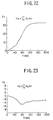
- FIGS.17 and 18 show variation in the magnitude V30 and direction ⁇ 30 with respect to elapsed time, respectively.
- the magnitude V30 and the direction ⁇ 30 are calculated as interval integral on Gx and Gy with respect to an interval of 30 ms.
- FIGS.19A and 19B show variation in the projective magnitude V30 ⁇ with respect to elapsed time when the angle ⁇ is set to ⁇ 1 to ⁇ 11;
- FIG.19A shows the case where ⁇ 0;
- FIG.19B shows the case where ⁇ 0.
- each threshold value fth( ⁇ n) must be set to be greater than the corresponding projective magnitude V30 ⁇ shown in FIGS.19A and 19B.
- FIGS.20 and 21 show variation in the x-component Gx and y-component Gy of the acceleration G with respect to elapsed time when the external force exerted on the vehicle has a magnitude which requires the airbags to be actuated.
- the external force which is sufficient to actuate the airbags is hereinafter referred to as a large force.
- FIGS.22 and 23 show variation in the x-component Vx and y-component Vy of the velocity V with respect to elapsed time which are obtained by Gx and Gy shown in FIGS.20 and 21, respectively.
- FIGS.24 and 25 show variation in the magnitude and the direction ⁇ of the velocity V shown in FIG.24 with respect to elapsed time which are calculated in accordance with Vx and Vy mentioned above, respectively.
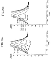
- FIGS.26A and 26B show variation in the projective magnitude V30 ⁇ with respect to elapsed time when the angle ⁇ is set to ⁇ 1 to ⁇ 11; FIG.26A shows the case where ⁇ 0; FIG.26B shows the case where ⁇ 0.
- FIGS.27 and 28 show variation in the magnitude V30 and direction ⁇ 30 with respect to time elapse, respectively.
- the magnitude V30 and the direction ⁇ 30 are calculated as a time interval integration of Gx and Gy with respect to an interval of 30 ms.
- FIGS.29A and 29B show variation in the projective magnitude V30 ⁇ with respect to elapsed time when the angle ⁇ is set from ⁇ 1 to ⁇ 11;
- FIG.29A shows a case where ⁇ 0;
- FIG.29B shows a case where ⁇ 0.
- each threshold value fth( ⁇ n) must be set to be smaller than the corresponding projective magnitude V30 ⁇ shown in FIGS.29A and 29B.
- the threshold value fth( ⁇ n) is set to be slightly greater than the maximum value of the projective magnitude V30 ⁇ n shown in FIGS.19A and 19B, the projective magnitude V30 ⁇ n exceeds the corresponding threshold value fth( ⁇ n) at the angle ⁇ of -75°, -60° and -45° in FIG.29B before a time period of 40 ms elapses.
- the determination to actuate the airbags is made if the projective magnitude V30 ⁇ n is greater than the corresponding threshold value fth( ⁇ n) at any one of the angles ⁇ 1 to ⁇ 11.
- a quick determination as to actuation of the airbags is achieved by considering rotation of the vehicle due to the external force applied in a direction oblique to the front-to-rear direction of the vehicle 12.
- the external force exerted on the vehicle 12 is determined by sensing the front-to-rear component and the side-to-side component of the acceleration generated in the vehicle 12.
- the directions of sensing the components are not limited to the front-to-rear direction and the side-to-side direction, and any directions may be selected if the external force can be calculated by synthesizing the components in such directions.
- the construction of the second embodiment is the same as that of the above-mentioned first embodiment as shown in FIG.3.
- the first embodiment determines the actuation of the airbags in accordance with the projective magnitude which is obtained from the synthesized vector in accordance with the feature values fx and fy.
- the second embodiment does not use the vector calculation as in the first embodiment to perform the determination for actuation of the airbags.
- FIG.31 is a flowchart of a process executed by the CPU 22a of the second embodiment.
- steps which are the same as the steps shown in FIG.5 are given the same reference numerals, and descriptions thereof will be omitted.
- the feature values fx and fy are calculated according to Gx and Gy in steps 100 and 102. Then, a column (hereinafter referred to as a reference column) to be referred to in the table shown in FIG.30 is determined, in step 300, in accordance with the feature value fy. The determination information is then read from the table at an intersection of the reference column and a row indicated by the feature value fx. It is then determined, in step 302, whether or not the determination information indicates "ON".
- step 114 If it is determined that the determination information indicates "ON”, the routine proceeds to step 114 to actuate the airbags and the routine is then ended. If it is determined that determination information does not indicate "ON”, the routine proceeds to step 100 to repeat steps 100 to 302.
- the determination of the actuation of the airbags can be made by referring to the table prepared beforehand without performing complex calculation.
- a reliable determination can be made with a simple operation.
- the determination of the actuation of the airbags may be made in accordance with a two-dimensional map in which the threshold value fxth is changed stepwise according to a value of fy.
- a column to be referred to in the two-dimensional map is determined first according to the value of fy. It is then determined whether or not fx is greater than fxth. If fx is greater than fxth, a determination is made to actuate the airbags.
- the airbags 14, 16, 18 and 20 are provided as occupant restraining means.
- other device such as a preloader which unwind an excessive length of seat belt may be provided as the occupant restraining means.
Description
Claims (9)
- An occupant restraint system (10) for a vehicle (12), an acceleration being generated on said vehicle when an external force is exerted on said vehicle, said occupant restraint system comprising:restraining means (M5) for restraining a passenger in said vehicle;external force assuming means (M1, M2, M3) for assuming a magnitude and a direction of the external force exerted on said vehicle and for calculating an external force vector on the basis of the magnitude and the direction of the external force;actuation determining means (M6) for determining actuation of said restraining means (M5); andprojective magnitude calculating means (M4) for calculating a projective magnitude of a projective vector obtained from said external force vector, said projective vector being a projection of said external force vector with respect to a predetermined direction; whereinsaid actuation determining means (M6) determines actuation of said restraining means (M5) by comparing said projective magnitude with a predetermined threshold value so that said restraining means (M5) is actuated when said projective magnitude is greater than said threshold value.
- The occupant restraint system as claimed in claim 1, wherein said external force assuming means comprises:first feature value extracting means (M1) for extracting a first feature value from a first component of said acceleration in a first direction, said first feature value representing a first vector of said external force with respect to said first direction;second feature value extracting means (M2) for extracting a second feature value from a second component of said acceleration in a second direction different from said first direction, said second feature value representing a second vector of said external force with respect to said second direction; andsynthesized vector calculating means (M3) for calculating a magnitude and a direction of a synthesized vector which is obtained by synthesizing said first vector and said second vector, said synthesized vector corresponding to said external force vector.
- The occupant restraint system as claimed in claim 2 wherein said first feature value and said second feature value are extracted by integration of said first component and said second component of said acceleration with respect to time, respectively.
- The occupant restraint system as claimed in claim 2, wherein said first feature value and said second feature value are extracted by n times integration of said first component and said second component of said acceleration with respect to time, where the n is an integer greater than 1.
- The occupant restraint system as claimed in claim 2, wherein said first feature value and said second feature value are extracted by interval integral on said first component and said second component of said acceleration with respect to time.
- The occupant restraint system as claimed in claim 2, wherein said first direction corresponds to a front-to-rear direction of said vehicle (12) and said second direction corresponds to a side-to-side direction of said vehicle (12).
- The occupant restraint system as claimed in claim 2, wherein said projective magnitude calculating means (M4) calculates said projective magnitude for a plurality of predetermined directions, and said actuation determining means (M6) compares each calculated projective magnitude with the corresponding threshold value determined for each of said predetermined directions, a determination to actuate said restraining means being made when said projective magnitude exceeds the corresponding threshold value at any one of said predetermined directions.
- The occupant restraint system as claimed in claim 7, wherein said predetermined directions are defined in a range from minus 90 degrees to plus 90 degrees with respect to a front-to-rear direction of said vehicle (12), said range divided into uniform intervals.
- The occupant restraint system as claimed in claim 8, wherein said intervals are 15 degrees.
Applications Claiming Priority (2)
| Application Number | Priority Date | Filing Date | Title |
|---|---|---|---|
| JP260528/94 | 1994-10-25 | ||
| JP6260528A JP3050061B2 (en) | 1994-10-25 | 1994-10-25 | Occupant restraint |
Publications (2)
| Publication Number | Publication Date |
|---|---|
| EP0709255A1 EP0709255A1 (en) | 1996-05-01 |
| EP0709255B1 true EP0709255B1 (en) | 1999-01-07 |
Family
ID=17349222
Family Applications (1)
| Application Number | Title | Priority Date | Filing Date |
|---|---|---|---|
| EP95116760A Expired - Lifetime EP0709255B1 (en) | 1994-10-25 | 1995-10-24 | Occupant restraint system actuated by a simple operation using a feature value |
Country Status (8)
| Country | Link |
|---|---|
| US (1) | US5740041A (en) |
| EP (1) | EP0709255B1 (en) |
| JP (1) | JP3050061B2 (en) |
| KR (1) | KR0182787B1 (en) |
| CN (1) | CN1043201C (en) |
| CA (1) | CA2161158A1 (en) |
| DE (1) | DE69507108T2 (en) |
| TW (2) | TW318459U (en) |
Families Citing this family (54)
| Publication number | Priority date | Publication date | Assignee | Title |
|---|---|---|---|---|
| JPH08246512A (en) * | 1995-03-07 | 1996-09-24 | Shinwa Musen Syst Kk | Water leak detector |
| US6095554A (en) * | 1995-06-15 | 2000-08-01 | Trw Inc. | Method and apparatus for sensing side impact crash conditions with an enhanced safing function |
| JP2973902B2 (en) * | 1995-11-06 | 1999-11-08 | トヨタ自動車株式会社 | Activation control device for occupant protection device |
| DE19609176A1 (en) * | 1996-03-11 | 1997-09-18 | Bosch Gmbh Robert | Method and arrangement for detecting a vehicle rollover |
| DE19609717A1 (en) * | 1996-03-13 | 1997-09-18 | Bosch Gmbh Robert | Arrangement for detecting rollover processes in vehicles |
| JP3333813B2 (en) | 1996-11-20 | 2002-10-15 | トヨタ自動車株式会社 | Startup control device for occupant protection device |
| DE19736840B4 (en) * | 1997-08-23 | 2006-01-26 | Volkswagen Ag | Method for situation-dependent triggering of a restraint system and restraint system |
| US6063132A (en) * | 1998-06-26 | 2000-05-16 | International Business Machines Corporation | Method for verifying design rule checking software |
| US6186539B1 (en) * | 1998-07-01 | 2001-02-13 | Trw Inc. | Method and apparatus for controlling an actuatable restraint device using crash severity indexing and crush zone sensor |
| DE19851981C2 (en) * | 1998-11-11 | 2000-09-14 | Daimler Chrysler Ag | Method for controlling an active occupant head protection system in a vehicle |
| JP3346472B2 (en) | 1999-02-01 | 2002-11-18 | トヨタ自動車株式会社 | Activation control device for occupant protection device |
| JP3436185B2 (en) | 1999-02-09 | 2003-08-11 | トヨタ自動車株式会社 | Activation control device for occupant protection device |
| US6834218B2 (en) * | 2001-11-05 | 2004-12-21 | Ford Global Technologies, Llc | Roll over stability control for an automotive vehicle |
| US7132937B2 (en) * | 2000-09-25 | 2006-11-07 | Ford Global Technologies, Llc | Wheel lift identification for an automotive vehicle using passive and active detection |
| US6904350B2 (en) | 2000-09-25 | 2005-06-07 | Ford Global Technologies, Llc | System for dynamically determining the wheel grounding and wheel lifting conditions and their applications in roll stability control |
| US6356188B1 (en) | 2000-09-25 | 2002-03-12 | Ford Global Technologies, Inc. | Wheel lift identification for an automotive vehicle |
| US7233236B2 (en) * | 2000-09-25 | 2007-06-19 | Ford Global Technologies, Llc | Passive wheel lift identification for an automotive vehicle using operating input torque to wheel |
| US7109856B2 (en) * | 2000-09-25 | 2006-09-19 | Ford Global Technologies, Llc | Wheel lifted and grounded identification for an automotive vehicle |
| US6520536B2 (en) | 2001-05-04 | 2003-02-18 | Trw Inc. | Method and apparatus for controlling an occupant side restraining device with enhanced side safing function |
| US6336499B1 (en) * | 2001-05-31 | 2002-01-08 | Hong Tsai Liu | CPU heat sink mounting structure |
| US6654674B2 (en) * | 2001-11-21 | 2003-11-25 | Ford Global Technologies, Llc | Enhanced system for yaw stability control system to include roll stability control function |
| US6556908B1 (en) | 2002-03-04 | 2003-04-29 | Ford Global Technologies, Inc. | Attitude sensing system for an automotive vehicle relative to the road |
| US7302331B2 (en) * | 2002-08-01 | 2007-11-27 | Ford Global Technologies, Inc. | Wheel lift identification for an automotive vehicle |
| US6941205B2 (en) * | 2002-08-01 | 2005-09-06 | Ford Global Technologies, Llc. | System and method for deteching roll rate sensor fault |
| US7079928B2 (en) * | 2002-08-01 | 2006-07-18 | Ford Global Technologies, Llc | System and method for determining a wheel departure angle for a rollover control system with respect to road roll rate and loading misalignment |
| US7003389B2 (en) * | 2002-08-01 | 2006-02-21 | Ford Global Technologies, Llc | System and method for characterizing vehicle body to road angle for vehicle roll stability control |
| US7194351B2 (en) * | 2002-08-01 | 2007-03-20 | Ford Global Technologies, Llc | System and method for determining a wheel departure angle for a rollover control system |
| US7085639B2 (en) * | 2002-08-01 | 2006-08-01 | Ford Global Technologies, Llc | System and method for characterizing the road bank for vehicle roll stability control |
| US6963797B2 (en) * | 2002-08-05 | 2005-11-08 | Ford Global Technologies, Llc | System and method for determining an amount of control for operating a rollover control system |
| US20040024504A1 (en) * | 2002-08-05 | 2004-02-05 | Salib Albert Chenouda | System and method for operating a rollover control system during an elevated condition |
| US20040024505A1 (en) * | 2002-08-05 | 2004-02-05 | Salib Albert Chenouda | System and method for operating a rollover control system in a transition to a rollover condition |
| US6961648B2 (en) | 2002-08-05 | 2005-11-01 | Ford Motor Company | System and method for desensitizing the activation criteria of a rollover control system |
| US7430468B2 (en) * | 2002-08-05 | 2008-09-30 | Ford Global Technologies, Llc | System and method for sensitizing the activation criteria of a rollover control system |
| US7085642B2 (en) * | 2002-08-05 | 2006-08-01 | Ford Global Technologies, Llc | Method and system for correcting sensor offsets |
| US9162656B2 (en) * | 2003-02-26 | 2015-10-20 | Ford Global Technologies, Llc | Active driven wheel lift identification for an automotive vehicle |
| US7239949B2 (en) * | 2003-02-26 | 2007-07-03 | Ford Global Technologies, Llc | Integrated sensing system |
| US7653471B2 (en) * | 2003-02-26 | 2010-01-26 | Ford Global Technologies, Llc | Active driven wheel lift identification for an automotive vehicle |
| US7136731B2 (en) * | 2003-06-11 | 2006-11-14 | Ford Global Technologies, Llc | System for determining vehicular relative roll angle during a potential rollover event |
| US7308350B2 (en) * | 2004-05-20 | 2007-12-11 | Ford Global Technologies, Llc | Method and apparatus for determining adaptive brake gain parameters for use in a safety system of an automotive vehicle |
| US7451032B2 (en) * | 2004-06-02 | 2008-11-11 | Ford Global Technologies, Llc | System and method for determining desired yaw rate and lateral velocity for use in a vehicle dynamic control system |
| US7640081B2 (en) | 2004-10-01 | 2009-12-29 | Ford Global Technologies, Llc | Roll stability control using four-wheel drive |
| US7715965B2 (en) | 2004-10-15 | 2010-05-11 | Ford Global Technologies | System and method for qualitatively determining vehicle loading conditions |
| US7668645B2 (en) * | 2004-10-15 | 2010-02-23 | Ford Global Technologies | System and method for dynamically determining vehicle loading and vertical loading distance for use in a vehicle dynamic control system |
| US7660654B2 (en) | 2004-12-13 | 2010-02-09 | Ford Global Technologies, Llc | System for dynamically determining vehicle rear/trunk loading for use in a vehicle control system |
| US7590481B2 (en) * | 2005-09-19 | 2009-09-15 | Ford Global Technologies, Llc | Integrated vehicle control system using dynamically determined vehicle conditions |
| US7600826B2 (en) * | 2005-11-09 | 2009-10-13 | Ford Global Technologies, Llc | System for dynamically determining axle loadings of a moving vehicle using integrated sensing system and its application in vehicle dynamics controls |
| US8121758B2 (en) * | 2005-11-09 | 2012-02-21 | Ford Global Technologies | System for determining torque and tire forces using integrated sensing system |
| JP4483925B2 (en) * | 2007-10-04 | 2010-06-16 | トヨタ自動車株式会社 | Collision determination device and occupant protection device |
| DE102008003339A1 (en) * | 2008-01-07 | 2009-07-09 | Robert Bosch Gmbh | Method and control device for controlling personal protective equipment for a vehicle |
| JP5871612B2 (en) * | 2011-12-26 | 2016-03-01 | 株式会社クボタ | Work vehicle |
| DE102014202666A1 (en) * | 2014-02-13 | 2015-08-13 | Robert Bosch Gmbh | Method and device for triggering at least one passenger protection device of a vehicle |
| DE102016222501A1 (en) * | 2016-11-16 | 2018-05-17 | Robert Bosch Gmbh | Method and device for evaluating acceleration |
| DE102017204390A1 (en) | 2017-03-16 | 2018-09-20 | Robert Bosch Gmbh | Method for triggering safety functions |
| JP7334695B2 (en) * | 2020-09-04 | 2023-08-29 | トヨタ自動車株式会社 | Vehicle occupant support device |
Citations (1)
| Publication number | Priority date | Publication date | Assignee | Title |
|---|---|---|---|---|
| JPH0656000A (en) * | 1992-08-04 | 1994-03-01 | Toyota Motor Corp | Collision detecting device |
Family Cites Families (19)
| Publication number | Priority date | Publication date | Assignee | Title |
|---|---|---|---|---|
| DE2745620A1 (en) * | 1977-10-11 | 1979-04-12 | Daimler Benz Ag | AIR BAG SYSTEM TO PROTECT THE OCCUPANTS OF A MOTOR VEHICLE IN THE EVENT OF ACCIDENTS |
| JPS605600A (en) * | 1983-06-23 | 1985-01-12 | 九州日本電気株式会社 | Loading device |
| DE3717427C3 (en) * | 1987-05-23 | 1994-09-01 | Deutsche Aerospace | Impact sensor for motor vehicles |
| DE3803426A1 (en) * | 1988-02-05 | 1989-08-17 | Audi Ag | METHOD FOR ACTIVATING A SECURITY SYSTEM |
| DE3816587A1 (en) * | 1988-05-16 | 1989-11-23 | Messerschmitt Boelkow Blohm | DEVICE FOR TRIGGERING A PASSIVE SAFETY DEVICE |
| JP2768710B2 (en) * | 1988-09-17 | 1998-06-25 | ローベルト・ボッシュ・ゲゼルシャフト・ミット・ベシュレンクテル・ハフツング | A device that activates a protection device that protects a vehicle occupant |
| JPH0343058U (en) * | 1989-09-06 | 1991-04-23 | ||
| JPH0443938A (en) * | 1990-06-11 | 1992-02-13 | Hitachi Ltd | Link mechanism analyzing method |
| JP2879611B2 (en) * | 1991-02-12 | 1999-04-05 | 本田技研工業株式会社 | Airbag device |
| DE4116336C1 (en) * | 1991-05-18 | 1992-06-11 | Messerschmitt-Boelkow-Blohm Gmbh, 8012 Ottobrunn, De | Passive safety device release assembly for motor vehicle occupant - has acceleration pick=ups with sensitivity axes directed to detect angle of frontal impact and supplying evaluating circuit |
| US5202831A (en) * | 1991-07-09 | 1993-04-13 | Trw Vehicle Safety Systems Inc. | Method and apparatus for controlling an occupant restraint system using real time vector analysis |
| US5282134A (en) * | 1991-08-19 | 1994-01-25 | Automotive Systems Laboratory, Inc. | Slant transform/signal space crash discriminator |
| JP2876363B2 (en) * | 1991-09-11 | 1999-03-31 | トヨタ自動車株式会社 | Side impact sensor system for side airbag device |
| WO1993009008A1 (en) * | 1991-10-31 | 1993-05-13 | Bruno Pineroli | Device for detecting running variables in a motor vehicle |
| JP3141534B2 (en) * | 1992-06-22 | 2001-03-05 | トヨタ自動車株式会社 | Airbag control device |
| JP3383816B2 (en) * | 1992-08-04 | 2003-03-10 | トヨタ自動車株式会社 | Vehicle airbag operation control device |
| JP3365799B2 (en) * | 1992-11-24 | 2003-01-14 | オリンパス光学工業株式会社 | Distance / speed measuring device |
| JP3214932B2 (en) * | 1992-11-24 | 2001-10-02 | オリンパス光学工業株式会社 | Distance / speed prediction device |
| US5484166A (en) * | 1994-07-22 | 1996-01-16 | Trw Vehicle Safety Systems Inc. | Method and apparatus for providing a deployment signal for a vehicle occupant restraint device during a side impact crash |
-
1994
- 1994-10-25 JP JP6260528A patent/JP3050061B2/en not_active Expired - Fee Related
-
1995
- 1995-08-11 TW TW085212044U patent/TW318459U/en unknown
- 1995-08-12 TW TW084108420A patent/TW309489B/zh active
- 1995-09-19 KR KR1019950030642A patent/KR0182787B1/en not_active IP Right Cessation
- 1995-10-19 US US08/545,225 patent/US5740041A/en not_active Expired - Fee Related
- 1995-10-23 CA CA002161158A patent/CA2161158A1/en not_active Abandoned
- 1995-10-24 EP EP95116760A patent/EP0709255B1/en not_active Expired - Lifetime
- 1995-10-24 DE DE69507108T patent/DE69507108T2/en not_active Expired - Fee Related
- 1995-10-24 CN CN95117640A patent/CN1043201C/en not_active Expired - Fee Related
Patent Citations (1)
| Publication number | Priority date | Publication date | Assignee | Title |
|---|---|---|---|---|
| JPH0656000A (en) * | 1992-08-04 | 1994-03-01 | Toyota Motor Corp | Collision detecting device |
Also Published As
| Publication number | Publication date |
|---|---|
| TW309489B (en) | 1997-07-01 |
| US5740041A (en) | 1998-04-14 |
| CA2161158A1 (en) | 1996-04-26 |
| TW318459U (en) | 1997-10-21 |
| EP0709255A1 (en) | 1996-05-01 |
| DE69507108D1 (en) | 1999-02-18 |
| JPH08119060A (en) | 1996-05-14 |
| CN1125670A (en) | 1996-07-03 |
| CN1043201C (en) | 1999-05-05 |
| DE69507108T2 (en) | 1999-07-01 |
| JP3050061B2 (en) | 2000-06-05 |
| KR960013870A (en) | 1996-05-22 |
| KR0182787B1 (en) | 1999-05-01 |
Similar Documents
| Publication | Publication Date | Title |
|---|---|---|
| EP0709255B1 (en) | Occupant restraint system actuated by a simple operation using a feature value | |
| JP2941216B2 (en) | Apparatus and method for controlling actuatable restraint | |
| US6594570B2 (en) | Systems and methods for controlling a vehicle-occupant protecting apparatus | |
| US5620203A (en) | Apparatus and method for tripping a safety system for the protection of an occupant of a vehicle | |
| US5285188A (en) | Vehicle collision detecting system | |
| JP2879611B2 (en) | Airbag device | |
| EP0785112B1 (en) | Method and apparatus for sensing impact crash conditions with safing function | |
| JPH10512514A (en) | Vehicle airbag deployment control device and method | |
| US20040068355A1 (en) | Vehicle occupant safety system | |
| JP2973902B2 (en) | Activation control device for occupant protection device | |
| JPH03159838A (en) | Air-bag spreading timing control device | |
| EP1026052B1 (en) | Activating control of a vehicle passenger restraint system | |
| US6270115B1 (en) | Air bag suppression system | |
| EP1322499A1 (en) | Apparatus and method for controlling activation of vehicle occupant protecting device | |
| JP3324220B2 (en) | Control device for occupant restraint system | |
| JP2002046571A (en) | System and method for controlling operable passive safety device | |
| JP2002059804A (en) | Start controller for air bag device | |
| JPH1067295A (en) | Occupant protective device of vehicle | |
| KR0154032B1 (en) | An air bag activating device in accordance with the transformation speed of a car and the method thereof | |
| KR960021947A (en) | Control system and method for airbag deployment, non-development situation determination and optimal start time determination | |
| WO1996027514A1 (en) | Collision detection device | |
| JPH0655993A (en) | Device for controlling operation of air bag for vehicle | |
| JP2541828Y2 (en) | Control device for collision safety device | |
| GB2369708A (en) | Control system for vehicle safety device | |
| JP4141999B2 (en) | Vehicle collision determination device |
Legal Events
| Date | Code | Title | Description |
|---|---|---|---|
| PUAI | Public reference made under article 153(3) epc to a published international application that has entered the european phase |
Free format text: ORIGINAL CODE: 0009012 |
|
| 17P | Request for examination filed |
Effective date: 19951025 |
|
| AK | Designated contracting states |
Kind code of ref document: A1 Designated state(s): DE FR GB |
|
| 17Q | First examination report despatched |
Effective date: 19961227 |
|
| GRAG | Despatch of communication of intention to grant |
Free format text: ORIGINAL CODE: EPIDOS AGRA |
|
| GRAG | Despatch of communication of intention to grant |
Free format text: ORIGINAL CODE: EPIDOS AGRA |
|
| GRAH | Despatch of communication of intention to grant a patent |
Free format text: ORIGINAL CODE: EPIDOS IGRA |
|
| GRAH | Despatch of communication of intention to grant a patent |
Free format text: ORIGINAL CODE: EPIDOS IGRA |
|
| GRAA | (expected) grant |
Free format text: ORIGINAL CODE: 0009210 |
|
| AK | Designated contracting states |
Kind code of ref document: B1 Designated state(s): DE FR GB |
|
| REF | Corresponds to: |
Ref document number: 69507108 Country of ref document: DE Date of ref document: 19990218 |
|
| ET | Fr: translation filed | ||
| PLBE | No opposition filed within time limit |
Free format text: ORIGINAL CODE: 0009261 |
|
| STAA | Information on the status of an ep patent application or granted ep patent |
Free format text: STATUS: NO OPPOSITION FILED WITHIN TIME LIMIT |
|
| 26N | No opposition filed | ||
| REG | Reference to a national code |
Ref country code: GB Ref legal event code: IF02 |
|
| REG | Reference to a national code |
Ref country code: GB Ref legal event code: 746 Effective date: 20041018 |
|
| REG | Reference to a national code |
Ref country code: FR Ref legal event code: D6 |
|
| PGFP | Annual fee paid to national office [announced via postgrant information from national office to epo] |
Ref country code: FR Payment date: 20051010 Year of fee payment: 11 |
|
| PGFP | Annual fee paid to national office [announced via postgrant information from national office to epo] |
Ref country code: GB Payment date: 20051019 Year of fee payment: 11 |
|
| PGFP | Annual fee paid to national office [announced via postgrant information from national office to epo] |
Ref country code: DE Payment date: 20051020 Year of fee payment: 11 |
|
| PG25 | Lapsed in a contracting state [announced via postgrant information from national office to epo] |
Ref country code: DE Free format text: LAPSE BECAUSE OF NON-PAYMENT OF DUE FEES Effective date: 20070501 |
|
| GBPC | Gb: european patent ceased through non-payment of renewal fee |
Effective date: 20061024 |
|
| REG | Reference to a national code |
Ref country code: FR Ref legal event code: ST Effective date: 20070629 |
|
| PG25 | Lapsed in a contracting state [announced via postgrant information from national office to epo] |
Ref country code: GB Free format text: LAPSE BECAUSE OF NON-PAYMENT OF DUE FEES Effective date: 20061024 |
|
| PG25 | Lapsed in a contracting state [announced via postgrant information from national office to epo] |
Ref country code: FR Free format text: LAPSE BECAUSE OF NON-PAYMENT OF DUE FEES Effective date: 20061031 |