EP0709059A2 - Apparat zum Ankuppeln akustischer Wellen an einen akustischen Wellenleiter - Google Patents
Apparat zum Ankuppeln akustischer Wellen an einen akustischen Wellenleiter Download PDFInfo
- Publication number
- EP0709059A2 EP0709059A2 EP95105145A EP95105145A EP0709059A2 EP 0709059 A2 EP0709059 A2 EP 0709059A2 EP 95105145 A EP95105145 A EP 95105145A EP 95105145 A EP95105145 A EP 95105145A EP 0709059 A2 EP0709059 A2 EP 0709059A2
- Authority
- EP
- European Patent Office
- Prior art keywords
- waveguide
- prism
- acoustic
- transducer
- waves
- Prior art date
- Legal status (The legal status is an assumption and is not a legal conclusion. Google has not performed a legal analysis and makes no representation as to the accuracy of the status listed.)
- Withdrawn
Links
Images

Classifications
-
- A—HUMAN NECESSITIES
- A61—MEDICAL OR VETERINARY SCIENCE; HYGIENE
- A61B—DIAGNOSIS; SURGERY; IDENTIFICATION
- A61B8/00—Diagnosis using ultrasonic, sonic or infrasonic waves
- A61B8/42—Details of probe positioning or probe attachment to the patient
- A61B8/4272—Details of probe positioning or probe attachment to the patient involving the acoustic interface between the transducer and the tissue
- A61B8/4281—Details of probe positioning or probe attachment to the patient involving the acoustic interface between the transducer and the tissue characterised by sound-transmitting media or devices for coupling the transducer to the tissue
-
- A—HUMAN NECESSITIES
- A61—MEDICAL OR VETERINARY SCIENCE; HYGIENE
- A61B—DIAGNOSIS; SURGERY; IDENTIFICATION
- A61B8/00—Diagnosis using ultrasonic, sonic or infrasonic waves
- A61B8/12—Diagnosis using ultrasonic, sonic or infrasonic waves in body cavities or body tracts, e.g. by using catheters
-
- G—PHYSICS
- G10—MUSICAL INSTRUMENTS; ACOUSTICS
- G10K—SOUND-PRODUCING DEVICES; METHODS OR DEVICES FOR PROTECTING AGAINST, OR FOR DAMPING, NOISE OR OTHER ACOUSTIC WAVES IN GENERAL; ACOUSTICS NOT OTHERWISE PROVIDED FOR
- G10K11/00—Methods or devices for transmitting, conducting or directing sound in general; Methods or devices for protecting against, or for damping, noise or other acoustic waves in general
- G10K11/02—Mechanical acoustic impedances; Impedance matching, e.g. by horns; Acoustic resonators
- G10K11/025—Mechanical acoustic impedances; Impedance matching, e.g. by horns; Acoustic resonators horns for impedance matching
-
- G—PHYSICS
- G10—MUSICAL INSTRUMENTS; ACOUSTICS
- G10K—SOUND-PRODUCING DEVICES; METHODS OR DEVICES FOR PROTECTING AGAINST, OR FOR DAMPING, NOISE OR OTHER ACOUSTIC WAVES IN GENERAL; ACOUSTICS NOT OTHERWISE PROVIDED FOR
- G10K11/00—Methods or devices for transmitting, conducting or directing sound in general; Methods or devices for protecting against, or for damping, noise or other acoustic waves in general
- G10K11/18—Methods or devices for transmitting, conducting or directing sound
- G10K11/24—Methods or devices for transmitting, conducting or directing sound for conducting sound through solid bodies, e.g. wires
-
- A—HUMAN NECESSITIES
- A61—MEDICAL OR VETERINARY SCIENCE; HYGIENE
- A61B—DIAGNOSIS; SURGERY; IDENTIFICATION
- A61B8/00—Diagnosis using ultrasonic, sonic or infrasonic waves
- A61B8/44—Constructional features of the ultrasonic, sonic or infrasonic diagnostic device
- A61B8/4444—Constructional features of the ultrasonic, sonic or infrasonic diagnostic device related to the probe
- A61B8/445—Details of catheter construction
-
- A—HUMAN NECESSITIES
- A61—MEDICAL OR VETERINARY SCIENCE; HYGIENE
- A61B—DIAGNOSIS; SURGERY; IDENTIFICATION
- A61B8/00—Diagnosis using ultrasonic, sonic or infrasonic waves
- A61B8/44—Constructional features of the ultrasonic, sonic or infrasonic diagnostic device
- A61B8/4483—Constructional features of the ultrasonic, sonic or infrasonic diagnostic device characterised by features of the ultrasound transducer
- A61B8/4488—Constructional features of the ultrasonic, sonic or infrasonic diagnostic device characterised by features of the ultrasound transducer the transducer being a phased array
-
- A—HUMAN NECESSITIES
- A61—MEDICAL OR VETERINARY SCIENCE; HYGIENE
- A61B—DIAGNOSIS; SURGERY; IDENTIFICATION
- A61B8/00—Diagnosis using ultrasonic, sonic or infrasonic waves
- A61B8/48—Diagnostic techniques
- A61B8/485—Diagnostic techniques involving measuring strain or elastic properties
Definitions
- the invention relates generally to the field of ultrasonic diagnostic probes and more particularly relates to the field of invasive ultrasound diagnostic probes.
- Ultrasonic probes provide a convenient and accurate way of gathering information about various structures of interest within a body being analyzed.
- the various structures of interest have acoustic impedances that are different from the acoustic impedance of a medium of the body surrounding the structures.
- such ultrasonic probes generate acoustic waves that are acoustically coupled from the probe into the medium of the body, so that the acoustic waves are transmitted into the body.
- medical ultrasonic probes provide a convenient and accurate way for a physician to collect imaging data of various anatomical parts, such as heart tissue or fetal tissue structures within a body of a patient.
- various anatomical parts such as heart tissue or fetal tissue structures within a body of a patient.
- the heart or fetal tissues of interest have acoustic impedances that are different than an acoustic impedance of bodily fluids surrounding the tissue structures.
- acoustic coupling is achieved by inserting a portion of the probe into the patient's body and through an incision of the blood vessel or artery.
- the probe includes a probe housing, which is inserted into the patients body.
- the probe housing contains an piezoelectric transducer that generates a beam of ultrasonic acoustic waves. The beam is transmitted through a wall of the probe housing and scans the interior of the blood vessel.
- a portion of the acoustic waves are weakly reflected by the various structures within the body, transmitted through the wall of the housing, and received by the transducer.
- the weakly reflected acoustic waves propagate through the transducer, they are electrically sensed by electrodes coupled thereto.
- imaging system components that are electrically coupled to the electrodes construct an image from the weakly reflected waves to illustrate spaced relation of the various tissue structures within the patient's body and qualities related to the acoustic impedance of the tissue structures. The physician views the reconstructed image on a display device coupled to the imaging system.
- acoustic waves are only weakly reflected by the tissue structures of interest, it is important to try to provide efficient acoustic transmission between the transducer and the body under examination.
- Such efficient acoustic transmission would insure that strength of the acoustic waves generated by the transducer is not excessively diminished as the waves are transmitted from the transducer into the medium of the body. Additionally, such efficient acoustic transmission would insure that strength of the weakly reflected waves are not excessively diminished as the reflected waves are received by the transducer from the medium of the body.
- the piezoelectric transducer may emit leakage currents inside the body, which could possibly induce life threatening fibrillation when the probe images a coronary artery.
- extended lengths of wires coupled to the electrodes of the inserted transducer act as antennas, which may receive undesirable radio frequency interference signals that could obscure electrical signals representative of an acoustic image.
- the present invention provides efficient coupling and transmission of a beam of acoustic waves between an ultrasonic transducer and a remotely located body under examination by the beam.
- the apparatus of the invention is preferably embodied as a catheter-type probe capable of imaging inside of a blood vessel, artery, or other tissue in a cavity of interest.
- the present invention includes a housing having an interior arranged so that the ultrasonic transducer is disposed therein.
- a prism is acoustically coupled with the transducer and with an acoustic waveguide having a longitudinal dimension extending outwardly from the interior of the housing.
- the acoustic prism is fixedly coupled with a proximate portion of the waveguide so as to provide efficient transmission of the beam of acoustic waves between the prism and the waveguide.
- the waveguide includes a core and a cladding surrounding the core.
- the prism is fixedly coupled with the core of the waveguide for efficiently guiding the acoustic waves into the core of the waveguide. Accordingly, the beam of acoustic waves is transmitted from the transducer, through the prism, and along the longitudinal dimension of the waveguide, to a distal portion of the waveguide.
- the distal portion of the waveguide is inserted into a remotely located cavity in the patient's body under examination.
- the distal portion of the waveguide emits the ultrasonic beam, scanning the tissue of interest. Accordingly, the invention provides efficient acoustic coupling between an ultrasonic transducer and a remotely located body under examination.
- the transducer is fixedly coupled with the housing.
- the waveguide is rotated within the housing, so that the distal portion of the waveguide rotationally scans the tissue of interest while the housing remains substantially stationary.
- the prism is fixed to the waveguide, the prism rotates along with the waveguide and substantially reduces any fluctuations in the acoustic waves as the acoustic wave is transmitted from the prism into the waveguide.
- a fluid material disposed between the surface of the transducer and the surface of the prism advantageously provides acoustic coupling there between.
- the transducer generates the beam of acoustic waves, which is incident on the prism and has a power level.
- the prism has a surface for reflecting the incident beam of acoustic waves to produce a reflected beam of acoustic waves having a power level.
- the power level of the incident beam of acoustic waves is adjusted based on feedback of the power level of the reflected beam of acoustic waves, so as to maintain the power level of the incident beam of acoustic waves at a desired level.
- the beam of acoustic waves generated by the transducer includes longitudinal waves.
- the prism has an acoustic impedance and the waveguide has an acoustic impedance sufficiently different than that of the prism so as to substantially separate the longitudinal waves from any shear waves by acoustic refraction at the interface. Such separation is desired because shear waves travel at a lower velocity than the longitudinal waves and tend to obscure an acoustic image provided by longitudinal waves reflected by the body under examination.
- the apparatus further includes an absorbing material coupled with a surface of the waveguide. The absorbing material is positioned at a location sufficiently near the refracted shear waves so as to substantially absorb the refracted shear waves. The location is sufficiently far from the refracted longitudinal waves so that the refracted longitudinal waves are substantially reflected within the waveguide, thereby providing for propagation of the refracted longitudinal waves along the longitudinal dimension or the waveguide.
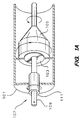
- Figs. 1A, 1B and 1C are views of the preferred embodiment of the invention.
- Figs. 1A, 1B and 1C are views of the preferred embodiment of the invention.
- the apparatus of the invention is preferably embodied as a catheter-type probe capable of imaging inside of a blood vessel, artery, or other tissue in a cavity of interest.
- the invention includes a housing 101.
- the housing has an interior arranged so that an ultrasonic transducer 103 is disposed therein.
- the transducer includes an annulus of a suitable piezoelectric ceramic such as lead zirconate titanate.
- a high voltage pulse generator (not shown in FIG. 1A) is coupled with electrodes disposed on opposing surfaces of the annulus for electrically exciting the piezoelectric ceramic to generate acoustic waves.
- the transducer additionally includes a plurality of concentric piezoelectric ceramic annuli adapted for operation as a phased acoustic array, so as to provide a focussed beam of acoustic waves.
- a signal delay is coupled with each of the piezoelectric ceramic annuli for variably phasing a respective acoustic wave generated by each one of the piezoelectric ceramic annuli.
- a prism 105 of a suitable material such as plexiglass is acoustically coupled with the transducer.
- An acoustic waveguide 107 having a longitudinal dimension extends outwardly from the interior of the housing. As shown in FIG 1A, the acoustic prism is fixedly coupled with a proximate portion of the waveguide so as to provide efficient transmission of the beam of acoustic waves between the prism and the waveguide.
- the waveguide includes a core 109 of a suitable material, such as aluminum, and a cladding material 111 surrounding the core.
- the cladding material is selected so that a velocity of longitudinal acoustic waves in the cladding is greater than a velocity of longitudinal acoustic waves in the core material.
- cladding surrounding an aluminum core is preferred, other suitable materials may be substituted therefor with beneficial results.
- the core comprises fused silica doped with germanium dioxide, while the cladding comprises un-doped silica.
- the prism 105 is fixedly coupled with the core 109 of the waveguide for efficiently guiding the acoustic waves into the core of the waveguide.
- the plexiglass is molded around the aluminum core as a resin, and the plexiglass resin is then hardened to be fixedly and acoustically coupled with the core of the waveguide.
- the beam of acoustic waves is transmitted from the transducer, through the prism, and into and along the longitudinal dimension of the waveguide, to a distal portion of the waveguide (not shown in FIGS 1A and 1B).
- the transducer 103 is fixedly coupled with the housing 101 as shown in FIG. 1A.
- the waveguide is rotated within the housing, manually or by using a motor coupled thereto, so that the distal portion of the waveguide rotationally scans the tissue of interest while the housing remains substantially stationary.
- the prism Since the prism is fixed to the waveguide, the prism rotates along with the waveguide as shown in FIG. 1A and substantially reduces any fluctuations in the acoustic waves as the acoustic wave is transmitted from the prism into the waveguide.
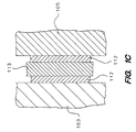
- a fluid material for example water, disposed between the surface of the transducer and the surface of the prism advantageously provides fluid acoustic coupling there between.
- an annulus of a suitable material 113 is disposed adjacent to the fluid for substantially providing acoustic impedance matching between the transducer and the prism.
- a suitable material 113 for example a suitable teflon composite
- the piezoelectric ceramic of the preferred embodiment of the transducer has an acoustic impedance of thirty Megarayls
- the plexiglass of the preferred embodiment of the prism has an acoustic impedance of three and a half Megarayls
- the preferred teflon composite has an acoustic impedance that substantially provides the desired impedance matching.
- FIG. 1B is a partial schematic diagram showing a cross-section view of the transducer 103, prism 105, and waveguide 107, which reveals the fluid material 112 disposed between the transducer and the prism.
- FIG. 1C is a detailed cut away view further revealing the fluid material 112 as well as the impedance matching material 113 disposed between the transducer 103 and the prism 105.
- the housing is not shown in FIGS. 1B and 1C.
- a surface area of an acoustic interface between the transducer and the prism of the preferred embodiment is large, while a surface area of an acoustic interface between the prism and the waveguide of the preferred embodiment is small.
- the large surface area provides enhanced acoustic transmission efficiency, while the small surface area provides only limited acoustic transmission efficiency.
- the fixed coupling provides enhanced acoustic transmission efficiency, while fluid coupling provides only limited acoustic transmission efficiency.
- the enhanced acoustic transmission efficiency provided by the fixed coupling between the prism and the waveguide substantially offsets the limited acoustic transmission efficiency provided by the relatively small surface area of the acoustic interface between the prism and the waveguide.
- the enhanced acoustic transmission provided by the relatively large surface area of the acoustic interface between the transducer and the prism substantially offsets the limited acoustic transmission provided by the fluid coupling between the transducer and the prism.
- the high voltage pulse generator 114 electrically excites the transducer to generate the beam of acoustic waves 115, which is incident on the prism and has a power level.
- acoustic waves are invisible.
- the beam generated by the transducer is representatively illustrated in FIG. 1B as a dashed line.
- the prism has a surface 117 for reflecting the incident beam of acoustic waves to produce a weakly reflected beam of acoustic waves 119 having a power level, and further to produce a strongly reflected beam of acoustic waves 120 that is guided into the waveguide.
- a sensor preferably a bridge coupler, 122 is coupled with the transducer so as to electrically sense the weakly reflected beam of acoustic waves 119.
- a feedback control circuit 123 is coupled with the pulse generator and sensor for adjusting the power level of the incident beam of acoustic waves 115 so as to maintain the power level of the incident beam of acoustic waves at a desired level, based upon feedback of the power level of the weakly reflected beam of acoustic waves.
- the beam of acoustic waves generated by the transducer includes longitudinal waves. It is theorized that the longitudinal waves incident on the interface between the prism and the waveguide are mode converted into both shear waves 125 and longitudinal waves 127.
- the prism has an acoustic impedance and the waveguide has an acoustic impedance sufficiently different than that of the prism so as to substantially separate the longitudinal waves 127 from any shear waves 125 by acoustic refraction at the interface.
- the waveguide has a higher acoustic impedance than the prism, so that the longitudinal waves 127 are guided along the longitudinal dimension of the waveguide at an advantageous initial angle.
- the plexiglass of the prism of the preferred embodiment has an acoustic impedance of three and a half Megarayls.
- the aluminum of the preferred embodiment of the waveguide has an acoustic impedance of seventeen Megarayls, which is sufficiently different from that of the prism for substantially separating the longitudinal waves 127 from the shear waves 125 as shown in FIG. 1B.
- the shear waves 125 will be separated form the longitudinal waves 127 by an angle of approximately forth five degrees. Such separation is desired because shear waves travel at a lower velocity than the longitudinal waves and tend to obscure an acoustic image provided by longitudinal waves reflected by the body under examination by the probe.
- the longitudinal waves 127 are guided along the longitudinal dimension of the waveguide at an advantageous initial angle of seventy two degrees with respect to the normal of the interface.
- the preferred embodiment further includes an acoustic absorbing material 129, for example an epoxy compound, coupled with a surface of the waveguide, as revealed by the cross sectional view of the prism and waveguide shown in FIG. 1B.
- the absorbing material is positioned at a location sufficiently near the refracted shear waves 125 so as to substantially absorb the refracted shear waves 125.
- the location is sufficiently far from the refracted longitudinal waves 127 so that the refracted longitudinal waves are substantially reflected within the waveguide as shown in FIG. 1B, thereby providing for propagation of the refracted longitudinal waves along the longitudinal dimension or the waveguide.
- the present invention provides efficient coupling and transmission of a beam of acoustic waves between an ultrasonic transducer and a remotely located body under examination by the beam.
- the waveguide and the prism are made from the same material, so as to substantially avoid mode conversion of the longitudinal waves into both longitudinal waves and shear waves.
Landscapes
- Life Sciences & Earth Sciences (AREA)
- Health & Medical Sciences (AREA)
- Physics & Mathematics (AREA)
- Engineering & Computer Science (AREA)
- Acoustics & Sound (AREA)
- Biomedical Technology (AREA)
- Surgery (AREA)
- Nuclear Medicine, Radiotherapy & Molecular Imaging (AREA)
- Pathology (AREA)
- Radiology & Medical Imaging (AREA)
- Multimedia (AREA)
- Heart & Thoracic Surgery (AREA)
- Medical Informatics (AREA)
- Molecular Biology (AREA)
- Biophysics (AREA)
- Animal Behavior & Ethology (AREA)
- General Health & Medical Sciences (AREA)
- Public Health (AREA)
- Veterinary Medicine (AREA)
- Investigating Or Analyzing Materials By The Use Of Ultrasonic Waves (AREA)
- Transducers For Ultrasonic Waves (AREA)
- Ultra Sonic Daignosis Equipment (AREA)
Applications Claiming Priority (2)
| Application Number | Priority Date | Filing Date | Title |
|---|---|---|---|
| US08/330,032 US5515850A (en) | 1993-06-07 | 1994-10-27 | Apparatus for coupling acoustic waves with an acoustic waveguide |
| US330032 | 1994-10-27 |
Publications (1)
| Publication Number | Publication Date |
|---|---|
| EP0709059A2 true EP0709059A2 (de) | 1996-05-01 |
Family
ID=23288012
Family Applications (1)
| Application Number | Title | Priority Date | Filing Date |
|---|---|---|---|
| EP95105145A Withdrawn EP0709059A2 (de) | 1994-10-27 | 1995-04-05 | Apparat zum Ankuppeln akustischer Wellen an einen akustischen Wellenleiter |
Country Status (3)
| Country | Link |
|---|---|
| US (1) | US5515850A (de) |
| EP (1) | EP0709059A2 (de) |
| JP (1) | JPH08206115A (de) |
Cited By (1)
| Publication number | Priority date | Publication date | Assignee | Title |
|---|---|---|---|---|
| ES2224901A1 (es) * | 2004-11-08 | 2005-03-01 | Juan Antonio Talavera Martin | Sistema de transmision basado en la propagacion de ondas elasticas a traves de cables electricos. |
Families Citing this family (5)
| Publication number | Priority date | Publication date | Assignee | Title |
|---|---|---|---|---|
| US5813998A (en) * | 1996-02-28 | 1998-09-29 | Hewlett-Packard Company | Method and system for coupling acoustic energy using an end-fire array |
| CA2762642C (en) | 2009-05-20 | 2018-07-10 | Imagenex Technology Corp. | Controlling an image element in a reflected energy measurement system |
| JP5472851B2 (ja) * | 2009-11-16 | 2014-04-16 | 学校法人千葉工業大学 | 超音波検査装置および検査方法 |
| US20130090576A1 (en) * | 2011-10-10 | 2013-04-11 | Foster B. Stulen | Surgical instrument with ultrasonic waveguide defining a fluid lumen |
| CA2983655C (en) * | 2015-04-24 | 2022-01-25 | Les Solutions Medicales Soundbite Inc. | Method and system for generating mechanical pulses |
Family Cites Families (5)
| Publication number | Priority date | Publication date | Assignee | Title |
|---|---|---|---|---|
| US4445892A (en) * | 1982-05-06 | 1984-05-01 | Laserscope, Inc. | Dual balloon catheter device |
| US5400788A (en) * | 1989-05-16 | 1995-03-28 | Hewlett-Packard | Apparatus that generates acoustic signals at discrete multiple frequencies and that couples acoustic signals into a cladded-core acoustic waveguide |
| US5029588A (en) * | 1989-06-15 | 1991-07-09 | Cardiovascular Imaging Systems, Inc. | Laser catheter with imaging capability |
| US5254112A (en) * | 1990-10-29 | 1993-10-19 | C. R. Bard, Inc. | Device for use in laser angioplasty |
| US5371483A (en) * | 1993-12-20 | 1994-12-06 | Bhardwaj; Mahesh C. | High intensity guided ultrasound source |
-
1994
- 1994-10-27 US US08/330,032 patent/US5515850A/en not_active Expired - Fee Related
-
1995
- 1995-04-05 EP EP95105145A patent/EP0709059A2/de not_active Withdrawn
- 1995-10-20 JP JP7272331A patent/JPH08206115A/ja active Pending
Cited By (2)
| Publication number | Priority date | Publication date | Assignee | Title |
|---|---|---|---|---|
| ES2224901A1 (es) * | 2004-11-08 | 2005-03-01 | Juan Antonio Talavera Martin | Sistema de transmision basado en la propagacion de ondas elasticas a traves de cables electricos. |
| WO2006051128A3 (es) * | 2004-11-08 | 2008-06-19 | Martin Juan Antonio Talavera | Sistema de transmisión basado en la propagación de ondas elásticas a través de cables eléctricos |
Also Published As
| Publication number | Publication date |
|---|---|
| JPH08206115A (ja) | 1996-08-13 |
| US5515850A (en) | 1996-05-14 |
Similar Documents
| Publication | Publication Date | Title |
|---|---|---|
| US5284148A (en) | Intracavity ultrasound diagnostic probe using fiber acoustic waveguides | |
| US9486143B2 (en) | Intravascular forward imaging device | |
| JP4575372B2 (ja) | 静電容量型超音波プローブ装置 | |
| US6190323B1 (en) | Direct contact scanner and related method | |
| CN101578069B (zh) | 用于三维心腔内超声心动图的导管和包括该导管的系统 | |
| US5217018A (en) | Acoustic transmission through cladded core waveguide | |
| US7229411B2 (en) | Imaging, therapy, and temperature monitoring ultrasonic system | |
| EP2787894B1 (de) | Bildgebungsvorrichtung zur visualisierung eines verstopften gefässes | |
| EP0646349A2 (de) | Ultraschall-Bildsonde | |
| EP1060367B1 (de) | Bestimmung der akustischen geschwindigkeit im knochen | |
| US20140180118A1 (en) | Catheter Assembly with a Shortened Tip | |
| CN101460094A (zh) | 多频多普勒超声波探头 | |
| GB2208138A (en) | Ultrasonic transducer array around a flexible tube | |
| US5509417A (en) | Method and apparatus for phased array coupling ultrasonic energy into an acoustic waveguide wire | |
| US5423319A (en) | Integrated impedance matching layer to acoustic boundary problems for clinical ultrasonic transducers | |
| US8021305B2 (en) | Ultrasound probe, ultrasonograph, and ultrasonography | |
| US5515850A (en) | Apparatus for coupling acoustic waves with an acoustic waveguide | |
| US20090318812A1 (en) | Ultrasound waveguide | |
| US5228447A (en) | Shockwave generator having an ultrasound applicator shielded from shockwaves | |
| KR20190092781A (ko) | 초음파 프로브 | |
| Sheljaskov et al. | A phased array antenna for simultaneous HIFU therapy and sonography | |
| JPH0630933A (ja) | 超音波探触子 | |
| JP2712975B2 (ja) | 体腔内用超音波プローブ | |
| CN120154305A (zh) | 角度型双模态内窥成像装置及系统 | |
| JP2964416B2 (ja) | 超音波探触子 |
Legal Events
| Date | Code | Title | Description |
|---|---|---|---|
| PUAI | Public reference made under article 153(3) epc to a published international application that has entered the european phase |
Free format text: ORIGINAL CODE: 0009012 |
|
| AK | Designated contracting states |
Kind code of ref document: A2 Designated state(s): DE FR GB NL |
|
| STAA | Information on the status of an ep patent application or granted ep patent |
Free format text: STATUS: THE APPLICATION HAS BEEN WITHDRAWN |
|
| 18W | Application withdrawn |
Withdrawal date: 19960828 |