EP0708988B1 - Diffusion vent for a rechargeable metal-air cell - Google Patents
Diffusion vent for a rechargeable metal-air cell Download PDFInfo
- Publication number
- EP0708988B1 EP0708988B1 EP94917505A EP94917505A EP0708988B1 EP 0708988 B1 EP0708988 B1 EP 0708988B1 EP 94917505 A EP94917505 A EP 94917505A EP 94917505 A EP94917505 A EP 94917505A EP 0708988 B1 EP0708988 B1 EP 0708988B1
- Authority
- EP
- European Patent Office
- Prior art keywords
- case
- gas
- gas exit
- cell
- recess
- Prior art date
- Legal status (The legal status is an assumption and is not a legal conclusion. Google has not performed a legal analysis and makes no representation as to the accuracy of the status listed.)
- Expired - Lifetime
Links
- 238000009792 diffusion process Methods 0.000 title description 6
- 239000012528 membrane Substances 0.000 claims abstract description 58
- 230000002209 hydrophobic effect Effects 0.000 claims abstract description 34
- 239000003792 electrolyte Substances 0.000 claims abstract description 25
- CURLTUGMZLYLDI-UHFFFAOYSA-N Carbon dioxide Chemical compound O=C=O CURLTUGMZLYLDI-UHFFFAOYSA-N 0.000 claims abstract description 22
- 239000000463 material Substances 0.000 claims abstract description 19
- 229910002092 carbon dioxide Inorganic materials 0.000 claims abstract description 11
- 239000001569 carbon dioxide Substances 0.000 claims abstract description 11
- 239000011148 porous material Substances 0.000 claims description 8
- 239000012530 fluid Substances 0.000 claims description 6
- 230000000717 retained effect Effects 0.000 claims description 6
- 239000002184 metal Substances 0.000 claims description 2
- 229910052751 metal Inorganic materials 0.000 claims description 2
- 230000000903 blocking effect Effects 0.000 claims 1
- 239000007789 gas Substances 0.000 abstract description 152
- XLYOFNOQVPJJNP-UHFFFAOYSA-N water Chemical compound O XLYOFNOQVPJJNP-UHFFFAOYSA-N 0.000 abstract description 18
- 238000004519 manufacturing process Methods 0.000 abstract description 7
- 210000004027 cell Anatomy 0.000 description 141
- 239000003570 air Substances 0.000 description 21
- 239000012080 ambient air Substances 0.000 description 14
- 239000004033 plastic Substances 0.000 description 9
- 229920003023 plastic Polymers 0.000 description 9
- 239000007788 liquid Substances 0.000 description 7
- 230000007246 mechanism Effects 0.000 description 7
- 239000000356 contaminant Substances 0.000 description 5
- -1 hydroxide ions Chemical class 0.000 description 5
- 238000000034 method Methods 0.000 description 5
- 230000002093 peripheral effect Effects 0.000 description 5
- 238000013022 venting Methods 0.000 description 5
- 241000282346 Meles meles Species 0.000 description 4
- 238000003860 storage Methods 0.000 description 4
- 238000003466 welding Methods 0.000 description 4
- UFHFLCQGNIYNRP-UHFFFAOYSA-N Hydrogen Chemical compound [H][H] UFHFLCQGNIYNRP-UHFFFAOYSA-N 0.000 description 3
- 238000001035 drying Methods 0.000 description 3
- 230000000694 effects Effects 0.000 description 3
- 238000003487 electrochemical reaction Methods 0.000 description 3
- 238000009931 pascalization Methods 0.000 description 3
- 238000007789 sealing Methods 0.000 description 3
- 238000009736 wetting Methods 0.000 description 3
- PXHVJJICTQNCMI-UHFFFAOYSA-N Nickel Chemical compound [Ni] PXHVJJICTQNCMI-UHFFFAOYSA-N 0.000 description 2
- 239000004743 Polypropylene Substances 0.000 description 2
- 239000011324 bead Substances 0.000 description 2
- 230000008901 benefit Effects 0.000 description 2
- 238000006243 chemical reaction Methods 0.000 description 2
- 238000010276 construction Methods 0.000 description 2
- 235000012489 doughnuts Nutrition 0.000 description 2
- 239000003822 epoxy resin Substances 0.000 description 2
- 239000001257 hydrogen Substances 0.000 description 2
- 229910052739 hydrogen Inorganic materials 0.000 description 2
- 238000002347 injection Methods 0.000 description 2
- 239000007924 injection Substances 0.000 description 2
- 230000005012 migration Effects 0.000 description 2
- 238000013508 migration Methods 0.000 description 2
- 229920000647 polyepoxide Polymers 0.000 description 2
- 229920005672 polyolefin resin Polymers 0.000 description 2
- 229920001155 polypropylene Polymers 0.000 description 2
- 239000007787 solid Substances 0.000 description 2
- 229920013683 Celanese Polymers 0.000 description 1
- 229920012485 Plasticized Polyvinyl chloride Polymers 0.000 description 1
- 239000004698 Polyethylene Substances 0.000 description 1
- 208000027418 Wounds and injury Diseases 0.000 description 1
- HCHKCACWOHOZIP-UHFFFAOYSA-N Zinc Chemical compound [Zn] HCHKCACWOHOZIP-UHFFFAOYSA-N 0.000 description 1
- 230000002745 absorbent Effects 0.000 description 1
- 239000002250 absorbent Substances 0.000 description 1
- 239000000853 adhesive Substances 0.000 description 1
- 230000001070 adhesive effect Effects 0.000 description 1
- 230000002411 adverse Effects 0.000 description 1
- 239000003513 alkali Substances 0.000 description 1
- 239000010425 asbestos Substances 0.000 description 1
- 230000000712 assembly Effects 0.000 description 1
- 238000000429 assembly Methods 0.000 description 1
- QVGXLLKOCUKJST-UHFFFAOYSA-N atomic oxygen Chemical compound [O] QVGXLLKOCUKJST-UHFFFAOYSA-N 0.000 description 1
- 230000004888 barrier function Effects 0.000 description 1
- 210000005056 cell body Anatomy 0.000 description 1
- 210000002421 cell wall Anatomy 0.000 description 1
- 230000008859 change Effects 0.000 description 1
- 238000004891 communication Methods 0.000 description 1
- 239000004020 conductor Substances 0.000 description 1
- 230000006378 damage Effects 0.000 description 1
- 230000007613 environmental effect Effects 0.000 description 1
- 238000010438 heat treatment Methods 0.000 description 1
- 208000014674 injury Diseases 0.000 description 1
- 229910052759 nickel Inorganic materials 0.000 description 1
- 239000001301 oxygen Substances 0.000 description 1
- 229910052760 oxygen Inorganic materials 0.000 description 1
- 239000004014 plasticizer Substances 0.000 description 1
- 229920000573 polyethylene Polymers 0.000 description 1
- 239000004800 polyvinyl chloride Substances 0.000 description 1
- 229920000915 polyvinyl chloride Polymers 0.000 description 1
- 238000003825 pressing Methods 0.000 description 1
- 230000008569 process Effects 0.000 description 1
- 238000012552 review Methods 0.000 description 1
- 229910052895 riebeckite Inorganic materials 0.000 description 1
- 230000035945 sensitivity Effects 0.000 description 1
- 229920003002 synthetic resin Polymers 0.000 description 1
- 239000000057 synthetic resin Substances 0.000 description 1
- 229920001169 thermoplastic Polymers 0.000 description 1
- 239000004416 thermosoftening plastic Substances 0.000 description 1
- 210000002268 wool Anatomy 0.000 description 1
- 229910052725 zinc Inorganic materials 0.000 description 1
- 239000011701 zinc Substances 0.000 description 1
Images




Classifications
-
- H—ELECTRICITY
- H01—ELECTRIC ELEMENTS
- H01M—PROCESSES OR MEANS, e.g. BATTERIES, FOR THE DIRECT CONVERSION OF CHEMICAL ENERGY INTO ELECTRICAL ENERGY
- H01M12/00—Hybrid cells; Manufacture thereof
- H01M12/08—Hybrid cells; Manufacture thereof composed of a half-cell of a fuel-cell type and a half-cell of the secondary-cell type
-
- H—ELECTRICITY
- H01—ELECTRIC ELEMENTS
- H01M—PROCESSES OR MEANS, e.g. BATTERIES, FOR THE DIRECT CONVERSION OF CHEMICAL ENERGY INTO ELECTRICAL ENERGY
- H01M50/00—Constructional details or processes of manufacture of the non-active parts of electrochemical cells other than fuel cells, e.g. hybrid cells
- H01M50/60—Arrangements or processes for filling or topping-up with liquids; Arrangements or processes for draining liquids from casings
- H01M50/668—Means for preventing spilling of liquid or electrolyte, e.g. when the battery is tilted or turned over
-
- H—ELECTRICITY
- H01—ELECTRIC ELEMENTS
- H01M—PROCESSES OR MEANS, e.g. BATTERIES, FOR THE DIRECT CONVERSION OF CHEMICAL ENERGY INTO ELECTRICAL ENERGY
- H01M50/00—Constructional details or processes of manufacture of the non-active parts of electrochemical cells other than fuel cells, e.g. hybrid cells
- H01M50/30—Arrangements for facilitating escape of gases
-
- H—ELECTRICITY
- H01—ELECTRIC ELEMENTS
- H01M—PROCESSES OR MEANS, e.g. BATTERIES, FOR THE DIRECT CONVERSION OF CHEMICAL ENERGY INTO ELECTRICAL ENERGY
- H01M50/00—Constructional details or processes of manufacture of the non-active parts of electrochemical cells other than fuel cells, e.g. hybrid cells
- H01M50/30—Arrangements for facilitating escape of gases
- H01M50/394—Gas-pervious parts or elements
-
- H—ELECTRICITY
- H01—ELECTRIC ELEMENTS
- H01M—PROCESSES OR MEANS, e.g. BATTERIES, FOR THE DIRECT CONVERSION OF CHEMICAL ENERGY INTO ELECTRICAL ENERGY
- H01M50/00—Constructional details or processes of manufacture of the non-active parts of electrochemical cells other than fuel cells, e.g. hybrid cells
- H01M50/10—Primary casings; Jackets or wrappings
- H01M50/172—Arrangements of electric connectors penetrating the casing
- H01M50/174—Arrangements of electric connectors penetrating the casing adapted for the shape of the cells
- H01M50/176—Arrangements of electric connectors penetrating the casing adapted for the shape of the cells for prismatic or rectangular cells
-
- Y—GENERAL TAGGING OF NEW TECHNOLOGICAL DEVELOPMENTS; GENERAL TAGGING OF CROSS-SECTIONAL TECHNOLOGIES SPANNING OVER SEVERAL SECTIONS OF THE IPC; TECHNICAL SUBJECTS COVERED BY FORMER USPC CROSS-REFERENCE ART COLLECTIONS [XRACs] AND DIGESTS
- Y02—TECHNOLOGIES OR APPLICATIONS FOR MITIGATION OR ADAPTATION AGAINST CLIMATE CHANGE
- Y02E—REDUCTION OF GREENHOUSE GAS [GHG] EMISSIONS, RELATED TO ENERGY GENERATION, TRANSMISSION OR DISTRIBUTION
- Y02E60/00—Enabling technologies; Technologies with a potential or indirect contribution to GHG emissions mitigation
- Y02E60/10—Energy storage using batteries
Definitions
- This invention relates generally to electrochemical cells and, more particularly, to vent systems for gas generated by an electrochemical cell, such as a metal-air cell.
- Metal-air cells include an air permeable cathode and a metallic anode separated by an aqueous electrolyte.
- oxygen from the ambient air is converted at the cathode to hydroxide ions
- zinc is oxidized at the anode
- reacts with hydroxide ions and water and electrons are released to provide electrical energy.
- the ambient air which enters the cell through the opening may cause the metal-air cell to fail due to a condition called flooding or drying out depending upon the relative humidity of the ambient air. If the relative humidity of the ambient air is high, then the battery may fail due to flooding. However, if the relative humidity of the ambient air was low, then the battery may fail due to drying out. Also, environmental contaminants, such as carbon dioxide, may enter through an opening with a mechanical sealing mechanism.
- the inner layer serves as a mechanism to dissolve or diffuse gas in the layer.
- the unlaminated gas passageway is shown to open to the atmosphere at opposite exterior edges of the battery.
- the unlaminated gas passageway may vary in width, length and configuration depending on the application. While Elliot discloses a membrane in which gases dissolve or diffuse before exiting the cell through an unlaminated passageway, Elliot's gas exit passageway has a large surface area which exposes the inner wrapper to relatively large amounts of outside air.
- Badger discloses a battery vent system particularly for use in automotive type storage batteries.
- Badger discloses a battery cover that has a plurality of openings which are covered by a microporous filter material. The microporous filter material is then covered by a guard member such that gas may pass laterally through the filter material to the atmosphere. In one embodiment, the gas passes up through the filter material into an elongate chamber open at both ends. Badger also exposes large areas of the filter material to the atmosphere.
- Murphy discloses a gas diffusion device for storage batteries.
- the storage battery is made of several battery cells which each have a vent to allow the passage of gas through a porous diffusion member which may be made of sheet asbestos or sheet wool.
- a supplementary cover extends for some distance beyond an opening on all sides and serves to protect the diffusion member from accidental mechanical injury or deposit of dirt or other foreign matter. Murphy also exposes the diffusion member to large amounts of ambient air.
- Providing a hermetic seal around leads which extend through a battery case is also important in reducing the effects that ambient air may have on a battery.
- plastic cell cases it is often a difficult manufacturing task to extend an electrode lead through an opening in the plastic case in a manner that provides a leak proof seal around the electrode. This is especially true when the case is formed in two parts joined at a seam, and one of the two electrodes of the cell is located within the battery case in a plane that is spaced from the plane in which the seam lies.
- a hole may be provided in the cell case near the electrode that is farthest from the seam of the battery case.
- cathode leads which pass through the seam of a cell case.
- the cases are manufactured in a manner which provides a hermetic seal around the electrode lead.
- U.S. Patent No. 3,026,365 to Hughes et al. discloses electric primary cells with cathode supports consisting of expanded or perforated nickel sheet. Each support has an outwardly directed pigtail or lead from the anode or cathode.
- the casing for the cell consists of pressed thermo-plastic sheets which may be polyvinyl chloride or other impermeable alkali-resistant material.
- the cathode is placed in a cathode casing section with its lead extending beyond the casing.
- the anode with its extending lead is placed in an anode casing section.
- Both the cathode and anode casings have flanges around the periphery of the casing.
- a highly plasticized polyvinyl chloride is placed between the cathode and anode assemblies. Even pressure is imposed to the flanges of the two casing sections to form a fluid-tight and hermetically sealed assembly with the leads extended beyond the casing. Migration of the plasticizer from the membrane placed between the anode and cathode permits the flanges of the anode and cathode casing to be welded together. The flanges of the casing are then cut near the outwardly directed leads.
- Hughes discloses an electrode lead extending through the seam of the cell case, Hughes does not deal with the problem of an electrode lead that is not aligned with a seam. Furthermore, Hughes requires flanges to be provided which must be cut after heating, as well as requiring a plasticized membrane between the casing sections to obtain the hermetic seal.
- U.S. Patent No. 4,664,994 to Koike et al. discloses an enclosed lead storage battery having a positive plate, negative plates and a separator and electrolyte held in position by a plate assembly. Leads for the battery assembly are coated with an epoxy resin which is then dried. A polyolefin resin having an excellent adhesiveness to epoxy resin is injection molded around the lead post so as to form a fitted doughnut shaped structure around the lead. The leads are then welded to their respective positive or negative plate. A jacket made of various kinds of synthetic resin is then heat sealed around the plate assembly and the extending leads. The jacket encloses the leads around the fitted doughnut shaped structures formed around the leads.
- Koike discloses an electrode lead extending through the seam of the cell case
- Koike requires that a polyolefin resin be molded around the electrode leads before sealing the leads with the case.
- Hughes and Koike require material additional to the casing to provide a seal around the outwardly directed leads of the cell.
- the present invention provides a system for venting gas from within a case housing an electrochemical cell.
- a cell case constructed according to the present invention has at least one gas exit hole defined from the exterior of the case to the interior of the case, the gas exit hole being sufficiently small to prevent excessive carbon dioxide intake from the atmosphere and to prevent excessive water loss from the battery, and a gas collection area defined by a recess formed in the case wall or by a gas diffuser attached to the case.
- the cross-sectional area of the gas exit hole is preferably 0.00516 square cm. (0.0008 square inches).
- the present invention may further provide a gas-permeable, hydrophobic membrane attached to the interior surface of the case so as to cover the gas diffuser thereby defining a boundary for the gas collection area.
- the present invention may further provide a second gas-permeable, hydrophobic membrane located between the gas diffuser and the interior surface of the case.
- the pore size of pores in the gas diffuser range approximately from 1-20 microns.
- the gas exit hole is preferably located at the geometric center of the gas diffuser and preferably the perimeter of the gas diffuser is circular in shape.
- Another embodiment of the present invention provides at least one recess defined on the interior surface of the case, the recess extending towards the exterior surface of the case so as to define a gas collection area, and at least one gas exit hole communicating with the atmosphere, having a smaller cross-sectional area than the cross-sectional area of the recess and extending from the exterior surface of the case to the recess.
- the present invention may further provide a gas-permeable, hydrophobic membrane attached to the interior surface of the case so as to cover the recess thereby defining a boundary of the gas collection area or may provide a gas-permeable membrane within the recess so as to cover the gas exit hole.
- the present invention may further utilize a gas diffuser which is retained or attached within the recess so as to cover the gas exit hole.
- the gas diffuser may be made of a material that will provide structural support to the case.
- the diameter of the pores of the gas diffuser range approximately from 1-20 microns.
- a gas-permeable, hydrophobic membrane is attached to the interior surface of the case and covers the gas diffuser and a second gas-permeable, hydrophobic membrane covers the gas exit hole and is located between the gas diffuser and the gas exit hole.
- the gas exit hole is preferably located at the geometric center of the recess, and preferably, the perimeter of the recess is circular in shape.
- the cross-sectional area is at least approximately 2.58 square centimeters (0.4 square inches).
- vent system of the present invention provides an opening defined in the case and a gas diffuser positioned to fill the opening.
- the present invention also provides a gas-permeable, hydrophobic membrane which covers the diffuser interior surface to help maintain the humidity within the case.
- the membrane covering the interior surface of the gas diffuser may also extend to cover the peripheral surfaces of the gas diffuser which fits into the opening, or the entire diffuser surface.
- the diameter of the pores of the diffuser range approximately from 1-20 microns.
- the cross-sectional area of the opening is approximately 2.58 square centimeters (0.4 square inches).
- the present invention may provide spaced apart gas exit holes to insure that gas may be exhausted from the case when the case is oriented in varying positions.
- An electrolyte partially fills the volume of the case and thereby defines a fluid volume and a gas volume within the case.
- the case may have an initial horizontal position which is defined by the position in which the gas exit holes, located on a surface of the case, face upward.
- the plurality of gas exit holes are spaced apart such that when the case is tilted to a 90° orientation from the horizontal position at least one of the gas exit holes is located above the maximum fluid level for that position and communicates with the gas volume.
- Each of the gas exit holes may be covered by a gas-permeable, hydrophobic membrane attached to the case.
- the case may comprise a plurality of case sections sealed together thereby defining a closed cell case, and in which at least one of the gas exit holes extends through at least one of the case sections.
- the gas exit holes are preferably aligned in a diagonal array from one corner of the perimeter of the case to an oppositely opposed corner of the case. Also, the gas exit holes may be positioned near the corners of the perimeter of the case, preferably with an exit hole also near the center of the case.
- a hermetically sealed air cathode lead is provided.
- the lead extends from the air cathode along a side wall to a seam of the cell case, and then out of the cell at the seam, which is welded to form a seal around the lead.
- the lead is perforated and plastic material is bonded through the openings in the lead.
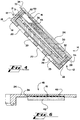
- Fig. 1 shows a top view of a cell case section embodying the vent arrangement of the preferred embodiment of the present invention.
- Fig. 2 shows a cross-sectional view of a metal-air cell embodying the preferred embodiment of the vent system of the present invention.
- Fig. 3 shows an exploded cross-sectional view of a portion of the cell wall shown in Fig. 1, showing the vent system of the present invention.
- Fig. 4 shows the metal-air cell shown in Fig. 2 oriented at an angled position.
- Fig. 5 shows the metal-air cell shown in Fig. 2 oriented in a vertical position.
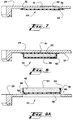
- Figs. 6-8 show cross-sectional views of alternate embodiments of the vent system of the present invention.
- Fig. 9a shows an exploded cross-sectional view of an alternate embodiment of the present invention.
- Fig. 9b shows an assembled view of the alternate embodiment of Fig. 9.
- Fig. 10a shows an exploded cross-sectional view of another alternate embodiment of the present invention.
- Fig. 10b shows an assembled view of the alternate embodiment of Fig. 10a.
- Fig. 11a shows an exploded cross-sectional view of another embodiment of the present invention.
- Fig. 11b shows an assembled view of the alternate embodiment of Fig. 11.
- Fig. 12 shows a top view of a cell case embodying the vent arrangement of any of the alternate embodiments of the present invention shown in Figs. 9-11.
- Fig. 13 shows a partial cross-sectional view of an alternate embodiment of the present invention.
- Fig. 1 and Fig. 2 show the preferred embodiment of the vent system 10 embodied in a cell case 12 for a metal-air cell 14.
- One or more vent systems 10 provide for exhausting excess gas generated by the cell 14 from within the cell case 12 in order to prevent excess pressure from building within the cell case 12.
- a gas exit hole 16 associated with each vent 10 extends through the cell case to provide a means for exhausting gases generated during operation of the metal-air cell 14.
- the cell case 12 includes a case body 18 consisting of a horizontal grid 19 defining a plurality of openings 20, and an upwardly extending peripheral side wall 21.
- An air cathode 22 is disposed within the cell case body 18, along the bottom of the cell case body 21.
- the openings 20 expose the cathode 22 to the atmosphere.
- a gas-permeable, hydrophobic membrane 23 extends along the interior of the cell case 12 between the cathode 22 and the openings 20 and along the sidewall 21 to prevent electrolyte leakage and/or moisture from exiting the cell 14, while allowing air to pass through for reaction at the cathode 22.
- a cathode support 28 secures the cathode 22 in position in the cell case body 18 as well as containing and supporting: an anode screen 30; an absorbent separator material 31; and an electrolyte 32.
- a cell lid 24 encloses the cell body 18 and meets the body 18 along a seam 34.
- An electrode lead 33 extends from the cathode 22 along the side wall 21 and through the seam 34, between the lid 24 and the cell side wall 21.
- the aqueous electrolyte 32 partially fills the cell case 12 thereby defining a liquid volume within the cell case 12.
- the remaining non-solid volume defines a gas volume that may change positions within the cell case 12 depending upon the volume of the cell case 12 filled by the aqueous electrolyte 32.
- the aqueous electrolyte 32 preferably fills approximately three quarters of the non-solid volume of the cell case 12. In Fig. 2, the liquid level is indicated by a dashed lines 35.
- the air-permeable cathode is not usually capable of supporting very high hydrostatic pressures, which makes the venting of excessive gases important to the operation of the metal-air cell 14. While it is possible to vent gases from within a cell case by opening and resealing a portion of a cell case, the hermeticity of the cell would sacrificed.
- the preferred embodiment of the vent system 10 shown embodied in the cell lid 24 comprises: a small gas exit hole 16; a recess 36 within the cell case section; a gas-permeable, hydrophobic membrane 40; a porous gas diffuser 42; and a gas-permeable, hydrophobic membrane 44.
- the gas-permeable hydrophobic membrane 40 is attached to the surface of the recess 36 such that the membrane 40 covers the gas exit hole 16.
- the recess 36 is preferably circular in shape.
- a gas diffuser 42 having a plurality of pores is placed adjacent to the membrane 40 within the recess 36 so as to cover the gas exit hole 16.
- the other membrane 44 may be attached to the interior surface of the cell case 12 so as to cover the recess 36 and the gas diffuser 42 which is fitted within the recess 36.
- the membrane 40 is preferably attached to the recess 36 at weld points 46 by ultrasonic welding techniques.
- a suitable membrane which has characteristics suitable for ultrasonic welding is a polypropylene membrane sold under the trademark Celgard 4599 which is available from Hoechet Celanese Corporation in Charlotte, North Carolina.
- the membrane preferably has a wetting angle of 90°. With a 90° wetting angle, liquid beads more readily than with a smaller wetting angle. The beading of liquid on the membrane allows gases generated in the cell to pass through the membrane. If the liquid did not bead on the membrane, a liquid layer could form across the membrane and thus prevent gas from exiting the cell.
- the membrane 44 may be a polypropylene material such as Celgard 2400 from the same supplier.
- the porous diffuser 42 may be held within the recess 36 by the membrane 44 which is also ultrasonically welded to the interior surface of the cell case 12 at weld points 47. Rather than being retained within the recess 36 by the membrane 44 the porous diffuser 42 may be also attached to the recess 36 by ultrasonic welding techniques.
- a gas diffuser suitable for use with the present invention is made of polyethylene and is available under the trademark Porex from Porex Corporation in Fairburn, Georgia. It should be appreciated that the membranes 40, 44 and the gas diffuser 42 may be retained or attached within the recess by other welding techniques known to those skilled in the art, or may be retained by adhesives, bonding materials, clamps or fasteners known by those skilled in the art.
- the vent system 10 of the present invention has a two fold function: to exhaust excess gas from the cell case 12; and to maintain the hermetic seal of the case 12 so that contaminants do not enter the cell and so that electrolyte is retained within the cell 14 during exhaustion of gas. This purpose is facilitated by the relatively large ratio of the gas collection area to the exit hole area for each vent.
- the embodiment of the present invention which utilizes a recess provides a gas collection area which may be defined by a membrane without a diffuser. When a diffuser is used within the recess, the thin portion of the cell lid that results from the recess may be structurally supported or strengthened by the use of the diffuser.
- An important aspect of the preferred embodiment of the present invention is that the vent system 10 uses hydrophobic material to maintain the hermeticity of the case 14.
- the gas-permeable, hydrophobic membrane 44 passes hydrogen gas but substantially prevents the water vapor from exiting the cell 14. For any small amount of water vapor that passes through the gas-permeable, hydrophobic membrane 44, the gas diffuser further impedes the migration of such water vapor from the cell 14.
- the diameter of the pores of the gas diffuser 42 preferably ranges from 1-20 microns.
- gas diffuser 42 By using a gas diffuser 42 with a large surface area, a large gas collection area is provided which also provides a greater distance of impedance through which water vapor must pass, thereby retaining more water vapor within the cell than is otherwise possible with gas-permeable, hydrophobic membranes 40 and 44 alone.
- the gas-permeable, hydrophobic membrane 40 located within the recess 36 immediately covering the gas exit hole 16 provides a further means for preventing electrolyte leakage from the cell 14 as well as being a barrier to prevent water and contaminants from entering the cell 14 from the atmosphere.
- the gas exit hole 16 extends from the exterior surface of the case 12 to the recess 36 so as to communicate with the atmosphere. Because the gas exit hole 16 is in constant communication with the atmosphere and because the water vapor pressure and the contents of the atmosphere are not easily controlled, the vent system 10 provides mechanisms to limit potential adverse effects of a gas exit hole which openly communicates with the atmosphere.
- the small size of the exit hole 16 and the hydrophobic membranes 40 and 44 prevent excess water and carbon dioxide from entering the cell 14 in the same manner as they prevents excess water from exiting the cell case 12, as discussed above. If excess water vapor were allowed to enter the cell case 12, then the metal-air cell 14 could fail due to flooding.
- the cross-sectional area of the gas exit hole 16 is smaller than the cross-sectional area of the recess 36. Further, the gas exit hole 16 is preferably very small so that carbon dioxide intake from the atmosphere is minimized as well as diffusion of water vapor from the atmosphere.
- the gas exit hole is approximately 0.00516 square centimeters (0.0008 square inches) but may range from 0.001935 to 0.0516 square centimeters (0.0003 to 0.008 square inches) and is preferably located at the geometric center of the recess 36.
- the cross-sectional area of the recess 36 is approximately 1.29 square centimeters (0.2 square inches) and circular in shape.
- Gas within the cell may collect in the recess 36 from a relatively large area and then escape through the small exit hole 16. It should be appreciated by those skilled in the art that the size of the gas exit hole 16 may be varied according to level of sensitivity of the battery components to atmospheric contaminants. Thereby, the vent system 10 of the preferred embodiment of the present invention provides multiple mechanisms within the one system to maintain optimum operating conditions within the cell 14 while exhausting the gases generated within the cell 14.
- the gas exit holes 16 are shown at spaced apart locations along the cell lid 24.
- the case may have an initial horizontal position which is defined by the position in which the gas exit holes, located on a surface of the case, face upward. Because the electrolyte 32 partially fills the cell case 12, the gas exit holes 16 are preferably spaced apart in a manner such that if the cell case 12 is oriented or positioned such that the electrolyte covers one of the gas exit holes 16, another gas exit hole 16 will be free to communicate with the gas volume defined within the cell case 12.
- At least one gas exit hole 16 will be positioned to communicate with the gas volume such that at least one gas exit hole 16 is above the maximum fluid level of the electrolyte fluid volume for the positions of orientation of the cell case 12 at least up to a 90° vertical orientation of the case from the horizontal position.
- Figs. 4 and 5 show different orientations of the cell 14.
- the position of the gas exit holes 16 may vary for a given amount of electrolyte 32.
- the gas exit holes 16 are aligned in a diagonal array as shown in Fig. 1 but may also be positioned near the edges or corners of the cell case 12.
- the number of gas exit holes 16 and the position of gas exit holes 16 may vary depending upon the amount of electrolyte 32 used within the cell case 12 and depending upon the shape and contents of the cell case 12.
- the number of gas exit holes 16 may vary according to the cross-sectional area of the gas exit holes 16. As the cross-sectional area of the gas exit holes 16 decrease, more gas exit holes 16 may be needed to exhaust a given amount of gas generated within the cell case 12.
- a plurality of posts 45 integrally molded with the case lid 24 may be provided.
- the posts 45 extend to support the membrane 44 against the pressure of the electrolyte 32 within the cell.
- the posts 45 may be arranged within the recess 36 to allow flow of gas to the exit hole 16 and so as not to block too much surface area of the membrane 44.
- the vent system 48 shown in Fig. 6 comprises a gas exit hole 16; a recess 36; one gas-permeable, hydrophobic membrane 40 located within the recess 36, and a porous gas diffuser 42 attached within the recess 36 by the methods of retaining the diffuser 42 discussed above.
- a vent system 49 comprises a gas exit hole 16 communicating between the atmosphere and the recess 36, the gas diffuser 42 located within the recess 36, and the gas-permeable, hydrophobic membrane 44 attached to the interior surface of the cell case 12 and covering the gas diffuser 42 and recess 36.
- gas exit hole 16 extends from the exterior surface of the cell case 12 to the interior surface of the cell case 12 so as to communicate with the gas-permeable, hydrophobic membrane 40 which is attached to the interior surface of the cell case 12 and covers the gas exit hole 16.
- the porous gas diffuser 42 is placed adjacent to the gas-permeable, hydrophobic membrane 40 so as to cover the gas exit hole 16.
- Another gas-permeable, hydrophobic membrane 44 may be attached to the interior surface of the cell case 12 so as to cover gas diffuser 42 as shown.
- Figs. 6-8 and 13 provide similar cell vent control mechanisms, as discussed above, through the use of various combinations and structures of the gas-permeable, hydrophobic membranes, gas exit holes, recesses, diffuser materials, and cell case sections.
- the moisture control for any given structure will vary depending upon the combination of, number of, or size of the various components used as part of the vent system 10.
- the embodiments illustrated are given by way of example, and many variations may be readily discerned by those skilled in the art and fall within the scope of the present invention.
- FIG. 9a another embodiment of a vent system 52 of the present invention is shown.
- an opening 50 is defined in the cell case 12 and extends through the exterior surface of the cell case 12 to the interior surface of the cell case 12.
- the gas diffuser 42 has a diffuser exterior surface 54 and a diffuser interior surface 56 connected by a diffuser peripheral surface 58 therebetween so as to define the volume of the diffuser 42.
- the diffuser 42 may be positioned to fill the opening 50 such that the diffuser exterior surface 54 communicates with the atmosphere.
- a gas-permeable, hydrophobic membrane 40 covers the diffuser peripheral surface 58 and the diffuser interior surface 56 so as to help maintain the equilibrium vapor pressure of the cell 14.
- the diffuser 42 may be tightly fitted within the opening 50 so as to fill opening 50 with the diffuser exterior surface 54 substantially parallel with the cell lid 24 or substantially within the same plane as the cell lid 24.
- the diffuser 42 may thereby enclose the opening 50 so as to become an integral part of the cell case 12.
- Fig. 9b depicts an assembled view of the embodiment shown in Fig. 9.
- FIG. 10a another embodiment of a vent system 59 is shown which is similar to the vent construction illustrated in Fig. 9.
- the vent system 59 illustrated in Fig. 10a differs from the vent system illustrated in Fig. 9 in that a gas-permeable, hydrophobic membrane covers the diffuser exterior surface 54 of the gas diffuser 42 rather than the interior surface 56 of the gas diffuser 42 as shown in Fig. 9.
- Fig. 10b depicts an assembled view of the embodiment shown in Fig. 10a.
- a vent system 61 is similar in construction to the embodiments illustrated in Fig. 9 and Fig. 10 except that the entire surface of the diffuser 42 is covered by the gas-permeable, hydrophobic membrane 40.
- Fig. 10a is similar in construction to the embodiments illustrated in Fig. 9 and Fig. 10 except that the entire surface of the diffuser 42 is covered by the gas-permeable, hydrophobic membrane 40.
- FIG. 11b depicts an assembled view of the embodiment shown in Fig. 11a.
- the diffuser may be snugly positioned or fitted within the opening 50 by pressing the diffuser into the opening in the direction indicated by the direction arrows 60.
- Fig. 12 a top view of any of the embodiments of the vent system 58, 59, or 61 illustrated in Figs. 9-11 is shown. The embodiment depicts the vents in a diagonal array as discussed above.
- Figs. 9-11 provide similar cell vent control mechanisms, as discussed above, through the use of various combinations and structures of the gas-permeable, hydrophobic membranes, openings, diffuser materials, and cell case sections.
- the embodiments shown in Figs. 9-11 allow more carbon dioxide to enter the cell than the embodiments shown in Figs. 2, 3, and 6-8.
- the moisture control for any given structure will vary depending upon the combination of, number of, or size of the various components used as part of the vent system 10.
- the embodiments illustrated are given by way of example, and many variations may be readily discerned by those skilled in the art and fall within the scope of the present invention.
- mechanisms which open and close to vent gases from a cell may allow electrolyte to escape from the cell or may allow contaminants such as carbon dioxide to enter the cell.
- the equilibrium vapor pressure of the cell could also vary depending upon the length of time in which the mechanical devices were opened and upon the relative humidity of the atmosphere.
- the ambient air which enters the cell during such a process may cause the metal-air cell to fail. If the equilibrium vapor pressure of the ambient air is high, then the battery may fail due to flooding. If the equilibrium vapor pressure of the ambient air is low, then the battery may fail due to a condition called drying out.
- the vent system of the present invention exhausts gases generated by the cell while minimizing the above discussed effects of exposure to an excessive amount of ambient air.
- electrode lead 33 is attached to and extends up from the cathode 22 along the peripheral side wall 21 of the case body 18 to fit through the seam 34 between the case body 18 and the case lid 24.
- the arrangement of the electrode lid 33 of the present invention provides the advantage of yielding a hermetically sealed case for a battery structure in which the electrodes of the cell are spaced at varying distances from the seam 34 of the case 12.
- the present invention provides an electrode lead for an electrode that is displaced a distance from the plane between the two case sections in which the seam 34 is formed.
- the seal around the cathode lead 33 of the present invention is leak proof and simple to manufacture.
- the electrode lead is made of a conducting material that may be a wire mesh or a perforated tab. It may be an integral extension of a conductive cathode current collector screen.
- the electrode lead 33 is extended from the electrode 22 to pass through the seam 34.
- the electrode lead 33 is first attached to or formed integrally with the electrode 22. Then the lead is extended along the cell side wall 21 and is bent out of the case at the seam 34.
- the plastic lid 24 of the case 12 is welded to the lower section 18 of the case, and the heated plastic extrudes through the perforated holes of the electrode lead. When the plastic cools, it contracts around the metal causing an injection molded type metal-to-plastic seal which is highly resistant to leakage.
Landscapes
- Chemical & Material Sciences (AREA)
- Chemical Kinetics & Catalysis (AREA)
- Electrochemistry (AREA)
- General Chemical & Material Sciences (AREA)
- Engineering & Computer Science (AREA)
- Manufacturing & Machinery (AREA)
- Gas Exhaust Devices For Batteries (AREA)
- Sealing Battery Cases Or Jackets (AREA)
- Hybrid Cells (AREA)
Abstract
Description
Claims (22)
- Electrochemical cell apparatus 14 having an anode 30 and a cathode 22 with a separator 31 positioned therebetween, said cell enclosed within a case 12, said case 12 having an interior surface and an exterior surface and said case having a gas exit hole 16 therein, characterised by:said electrochemical cell 14 being a metal air cell having an anode 30 and an air cathode 22;said separator 31 dividing said case 12 and effectively blocking any gas path from said anode 30 to said cathode 22; andsaid gas exit hole 16 communicating with a recess 36 defined on the interior surface of said case 12 on the anode side of said separator 16, said recess 36 extending towards the exterior surface of said case so as to define a gas collection area, and said gas exit hole communicating with the atmosphere, having a smaller cross-sectional area than the cross-sectional area of said recess 36, and extending from the exterior surface of said case 12 on the anode side of said separator 16 to said recess 36.
- The apparatus of claim 1 further characterised by a gas-permeable, hydrophobic membrane 44 attached to said interior surface of said case 12 so as to cover said recess 36 thereby defining a boundary of said gas collection area.
- The apparatus of claim 1 or claim 2 further characterised by a gas diffuser 42 having a plurality of pores, retained within said recess 36 and covering said gas exit hole 16.
- The apparatus of claim 3 wherein said gas diffuser 42 provides structural support to said case 12.
- The apparatus of claim 3 or claim 4 wherein the diameter of the pores of said gas diffuser 42 range approximately from 1-20 microns.
- The apparatus of any of claims 3-5 further characterised by a second gas-permeable, hydrophobic membrane 40 covering said gas exit hole 16 and located between said gas diffuser 42 and said gas exit hole 16.
- The apparatus of any preceding claim wherein said recess 36 has a geometric center and wherein said gas exit hole 16 is located at said geometric center.
- The apparatus of claim 7 wherein the perimeter of said recess 36 is circular.
- The apparatus of any preceding claim wherein the cross-sectional area of said recess 36 is approximately 258 mm2 .
- The apparatus of claim 9 wherein the cross-sectional area of said gas exit hole 16 ranges approximately from 0.19mm2 to 5.16mm2 .
- The apparatus of claim 1 wherein said size of said gas exit hole 16 is sufficiently small to minimize excessive carbon dioxide intake from the atmosphere.
- The apparatus of claim 2 and further comprising a gas permeable structure 42 supporting said membrane 44.
- Apparatus according to any preceding claim having an electrolyte 32 partially filling the volume of said case 12, thereby defining a fluid volume and a gas volume within said case 12, and a plurality of gas exit holes 16, said case having an initial horizontal position defined by the position in which said gas exit holes face upward, said exit holes being spaced apart such that at least one of said gas exit holes is located above the maximum fluid level for any position of orientation of said case from the horizontal to at least a 90° vertical orientation so that at least said one of said gas exit holes communicates with said gas volume; and
each of said gas exit holes being covered by a gas-permeable, hydrophobic membrane 44 attached to said case 16. - The apparatus of claim 13 wherein said case 16 comprises a plurality of case sections 18, 24 sealed together, thereby defining a closed cell case, and wherein said at least one of said gas exit holes 16 extends through at least one of said case sections.
- The apparatus of claim 14 wherein said plurality of gas exit holes 16 each extend through the same case section 24.
- The apparatus of claim 14 or claim 15 wherein the perimeter of at least one of said case sections 18, 24 is polygonal in shape.
- The apparatus of claim 16 wherein a plurality of said gas exit holes 16 are aligned in a diagonal array from one corner of said perimeter to the opposite corner of said perimeter.
- The apparatus of claim 16 wherein a plurality of said gas exit holes are aligned from one corner to said perimeter to the oppositely opposed side of said perimeter.
- The apparatus of claim 16 wherein a plurality of said gas exit holes are positioned near the corners of said perimeter.
- The apparatus of any of claims 14-19 wherein at least one of said gas exit holes 16 is positioned in a center portion of one of said case sections.
- Apparatus according to any preceding claim and further comprising an electrode lead 33 attached to said air cathode 22 and extending upwardly along an interior surface of said case 12 and exiting therefrom at the intersection of a case body 18 and a case lid 24, said case lid 24 being welded to said case body 18 so as to form a liquid-tight seal around said electrode lead 33.
- The metal-air cell of claim 21 wherein said electrode lead 33 is porous at the location at which it exits said case 12, and the material of said case 12 passed through openings in said lead 33 when welded.
Applications Claiming Priority (3)
| Application Number | Priority Date | Filing Date | Title |
|---|---|---|---|
| US08/071,844 US5362577A (en) | 1993-06-04 | 1993-06-04 | Diffusion vent for a rechargeable metal-air cell |
| PCT/US1994/006173 WO1994029908A2 (en) | 1993-06-04 | 1994-06-02 | Diffusion vent for a rechargeable metal-air cell |
| US71844 | 2002-02-08 |
Publications (2)
| Publication Number | Publication Date |
|---|---|
| EP0708988A1 EP0708988A1 (en) | 1996-05-01 |
| EP0708988B1 true EP0708988B1 (en) | 1998-01-28 |
Family
ID=22103951
Family Applications (1)
| Application Number | Title | Priority Date | Filing Date |
|---|---|---|---|
| EP94917505A Expired - Lifetime EP0708988B1 (en) | 1993-06-04 | 1994-06-02 | Diffusion vent for a rechargeable metal-air cell |
Country Status (8)
| Country | Link |
|---|---|
| US (1) | US5362577A (en) |
| EP (1) | EP0708988B1 (en) |
| JP (1) | JP2865424B2 (en) |
| AT (1) | ATE162908T1 (en) |
| AU (1) | AU6920294A (en) |
| CA (1) | CA2164132C (en) |
| DE (1) | DE69408324T2 (en) |
| WO (1) | WO1994029908A2 (en) |
Families Citing this family (74)
| Publication number | Priority date | Publication date | Assignee | Title |
|---|---|---|---|---|
| US5560999A (en) * | 1993-04-30 | 1996-10-01 | Aer Energy Resources, Inc. | Air manager system for recirculating reactant air in a metal-air battery |
| US5721064A (en) * | 1993-04-30 | 1998-02-24 | Aer Energy Resources Inc. | Air manager system for reducing gas concentrations in a metal-air battery |
| US5563004A (en) * | 1995-03-21 | 1996-10-08 | Aer Energy Resources, Inc. | Rechargeable metal-air electrochemical cell with hydrogen recombination and end-of-charge indicator |
| US5506067A (en) * | 1995-04-04 | 1996-04-09 | Aer Energy Resources, Inc. | Rechargeable electrochemical cell and cell case therefor with vent for use in internal recombination of hydrogen and oxygen |
| US5486429A (en) * | 1995-04-24 | 1996-01-23 | Aer Energy Resources, Inc. | Diffusion vent for a rechargeable metal-air cell |
| US5569551A (en) * | 1995-04-24 | 1996-10-29 | Aer Energy Resources Inc. | Dual air elecrtrode cell |
| US6040074A (en) * | 1995-05-05 | 2000-03-21 | Rayovac Corporation | Metal-air cathode can, and electrochemical cell made therewith |
| US5733676A (en) * | 1995-05-05 | 1998-03-31 | Rayovac Corporation | Metal-air cathode can and electrochemical cell made therewith |
| KR0138556B1 (en) * | 1995-06-14 | 1998-06-15 | 김광호 | Water-proof case assembly of battery electronic device |
| US5639568A (en) * | 1995-10-16 | 1997-06-17 | Aer Energy Resources, Inc. | Split anode for a dual air electrode cell |
| US5919582A (en) * | 1995-10-18 | 1999-07-06 | Aer Energy Resources, Inc. | Diffusion controlled air vent and recirculation air manager for a metal-air battery |
| US5691074A (en) * | 1995-10-18 | 1997-11-25 | Aer Energy Resources, Inc. | Diffusion controlled air vent for a metal-air battery |
| DE19635180B4 (en) * | 1996-08-30 | 2006-10-12 | Robert Bosch Gmbh | Housing for a drive device |
| US5985475A (en) * | 1997-06-17 | 1999-11-16 | Aer Energy Resources, Inc. | Membrane for selective transport of oxygen over water vapor and metal-air electrochemical cell including said membrane |
| US6106962A (en) | 1997-09-24 | 2000-08-22 | Aer Energy Resources Inc. | Air manager control using cell voltage as auto-reference |
| US6239508B1 (en) | 1997-10-06 | 2001-05-29 | Reveo, Inc. | Electrical power generation system having means for managing the discharging and recharging of metal fuel contained within a network of metal-air fuel cell battery subsystems |
| US6306534B1 (en) | 1997-10-06 | 2001-10-23 | Reveo, Inc. | Metal-air fuel cell battery systems employing means for discharging and recharging metal-fuel cards |
| US6287715B1 (en) | 1997-10-06 | 2001-09-11 | Reveo, Inc. | Metal-air fuel cell battery system having means for controlling discharging and recharging parameters for improved operating efficiency |
| US6558829B1 (en) | 1997-10-06 | 2003-05-06 | Reveo, Inc. | Appliance with refuelable and rechargeable metal-air fuel cell battery power supply unit integrated therein |
| US6299997B1 (en) | 1997-10-06 | 2001-10-09 | Reveo, Inc. | Ionically-conductive belt structure for use in a metal-air fuel cell battery system and method of fabricating the same |
| US6641943B1 (en) | 1997-10-06 | 2003-11-04 | Reveo, Inc. | Metal-air fuel cell battery system having means for recording and reading operating parameters during discharging and recharging modes of operation |
| US6348277B1 (en) | 1997-10-06 | 2002-02-19 | Reveo, Inc. | Method of and system for producing and supplying electrical power to an electrical power consuming device using a metal-air fuel cell battery (FCB) module and a supply of metal-fuel cards |
| US6296960B1 (en) | 1997-10-06 | 2001-10-02 | Reveo, Inc. | System and method for producing electrical power using metal-air fuel cell battery technology |
| US6335111B1 (en) | 1997-10-06 | 2002-01-01 | Reveo, Inc. | Metal-air fuel cell battery system employing a plurality of moving cathode structures for improved volumetric power density |
| US6451463B1 (en) | 1997-10-06 | 2002-09-17 | Reveo, Inc. | Electro-chemical power generation systems employing arrays of electronically-controllable discharging and/or recharging cells within a unity support structure |
| US6569555B1 (en) | 1997-10-06 | 2003-05-27 | Reveo, Inc. | Refuelable and rechargeable metal-air fuel cell battery power supply unit for integration into an appliance |
| US6228519B1 (en) | 1997-10-06 | 2001-05-08 | Reveo, Inc. | Metal-air fuel cell battery systems having mechanism for extending the path length of metal-fuel tape during discharging and recharging modes of operation |
| US6472093B2 (en) | 1997-10-06 | 2002-10-29 | Reveo, Inc. | Metal-air fuel cell battery systems having a metal-fuel card storage cartridge, insertable within a fuel cartridge insertion port, containing a supply of substantially planar discrete metal-fuel cards, and fuel card transport mechanisms therein |
| US6068944A (en) * | 1997-10-24 | 2000-05-30 | Aer Energy Resources, Inc. | Air distributors for metal-air cells |
| US6087029A (en) * | 1998-01-06 | 2000-07-11 | Aer Energy Resources, Inc. | Water recovery using a bi-directional air exchanger for a metal-air battery |
| US6436571B1 (en) | 1998-03-06 | 2002-08-20 | Rayovac Corporation | Bottom seals in air depolarized electrochemical cells |
| US6660418B1 (en) | 1998-06-15 | 2003-12-09 | Aer Energy Resources, Inc. | Electrical device with removable enclosure for electrochemical cell |
| US6248464B1 (en) | 1998-12-18 | 2001-06-19 | Christopher S. Pedicini | Air-managing system for metal-air battery using resealable septum |
| US6168877B1 (en) | 1998-12-18 | 2001-01-02 | Aer Energy Resources, Inc. | Air-managing system for metal-air battery using resealable septum |
| US6235418B1 (en) * | 1998-12-18 | 2001-05-22 | Aer Energy Resources, Inc. | Uniform shell for a metal-air battery stack |
| US6299998B1 (en) | 1999-03-15 | 2001-10-09 | Reveo, Inc. | Movable anode fuel cell battery |
| US6653003B1 (en) | 1999-10-12 | 2003-11-25 | Reveo Inc. | Fuel cell support and electrical interconnector |
| JP3959220B2 (en) * | 2000-02-04 | 2007-08-15 | 株式会社エスアイアイ・マイクロパーツ | Non-aqueous electrolytic battery for surface mounting and electric double layer capacitor for surface mounting |
| US7147952B1 (en) | 2000-02-10 | 2006-12-12 | Cmc Magnetics Corporation | Metal-air cell having an adjustable air inlet |
| US6558825B1 (en) | 2000-05-12 | 2003-05-06 | Reveo, Inc. | Fuel containment and recycling system |
| US6558828B1 (en) | 2000-05-26 | 2003-05-06 | Eveready Battery Company, Inc. | Zn/air cell performance in extreme humidity by controlling hydrophobic layer porosity |
| US6824915B1 (en) | 2000-06-12 | 2004-11-30 | The Gillette Company | Air managing systems and methods for gas depolarized power supplies utilizing a diaphragm |
| US6472089B1 (en) | 2000-06-13 | 2002-10-29 | Eveready Battery Company, Inc. | Bottom cover design for battery with reverse protection |
| US6759159B1 (en) | 2000-06-14 | 2004-07-06 | The Gillette Company | Synthetic jet for admitting and expelling reactant air |
| US6953637B2 (en) * | 2001-06-01 | 2005-10-11 | Energy Related Devices, Inc. | Catalytic hydrogen vent filter for batteries |
| US7276142B2 (en) * | 2002-02-12 | 2007-10-02 | Thermo Orion Inc. | Combination pH electrode with stable standard potential |
| US7678492B2 (en) * | 2002-05-18 | 2010-03-16 | Compagnie Plastic Omnium | Battery vent and pressure blowout relief frit |
| US20070050996A1 (en) * | 2005-09-06 | 2007-03-08 | Fred Schnak | Razors |
| US20070141450A1 (en) * | 2005-12-21 | 2007-06-21 | General Electric Company | Rechargeable fuel cell with double cathode |
| WO2007078276A2 (en) * | 2005-12-23 | 2007-07-12 | Utc Power Corporation | Pem fuel cell power plant with venting system |
| US7976992B2 (en) * | 2008-05-24 | 2011-07-12 | Utc Power Corp. | Non-circulating coolant PEM fuel cell power plant with antifreeze back pressure air venting system |
| JP5088378B2 (en) | 2008-10-30 | 2012-12-05 | トヨタ自動車株式会社 | Metal-air battery and metal-air battery manufacturing method |
| JP5062322B2 (en) | 2008-11-27 | 2012-10-31 | トヨタ自動車株式会社 | Air secondary battery |
| US20120028089A1 (en) * | 2009-04-30 | 2012-02-02 | Jyrki Mustakallio | Gas release from a battery cell |
| TW201119122A (en) * | 2009-11-17 | 2011-06-01 | Genius Toy Taiwan Co Ltd | Fuel cell module |
| EP2613401B1 (en) * | 2010-08-31 | 2016-04-06 | Honda Motor Co., Ltd. | Metal-oxygen battery |
| CN102038416B (en) * | 2010-12-24 | 2012-05-09 | 南京鹏力塑料科技有限公司 | Outer tube bayonet mechanism of telescopic straw and working method thereof |
| DE102011004799B4 (en) * | 2011-02-25 | 2012-09-27 | Varta Microbattery Gmbh | Status indicator for temperature-sensitive goods |
| US9368989B2 (en) | 2011-03-22 | 2016-06-14 | Argopower, Llc | Battery charger and fuel cell |
| WO2014033822A1 (en) * | 2012-08-28 | 2014-03-06 | 日立ビークルエナジー株式会社 | Rectangular secondary battery |
| WO2015171849A2 (en) | 2014-05-07 | 2015-11-12 | Open Water Power, Incorporated | Hydrogen management in electrochemical systems |
| JP6416536B2 (en) * | 2014-08-07 | 2018-10-31 | 日本協能電子株式会社 | Air battery |
| JP6532659B2 (en) * | 2014-08-07 | 2019-06-19 | 日本協能電子株式会社 | Air battery |
| CN107004928B (en) * | 2014-12-02 | 2020-05-26 | 日本碍子株式会社 | Zinc air secondary battery |
| JP6680484B2 (en) * | 2015-08-17 | 2020-04-15 | シャープ株式会社 | Metal-air batteries, metal-air batteries, and mobiles |
| KR101778059B1 (en) | 2015-11-11 | 2017-09-14 | 주식회사 이엠따블유에너지 | Zinc-air cell |
| JP7004461B2 (en) | 2017-08-07 | 2022-01-21 | シャープ株式会社 | How to manufacture metal-air batteries and metal-air batteries |
| KR102804031B1 (en) | 2019-08-27 | 2025-05-09 | 주식회사 엘지에너지솔루션 | The Case For Secondary Battery And The Method For Manufacturing Gas Discharger |
| KR102742762B1 (en) * | 2019-09-23 | 2024-12-16 | 주식회사 엘지에너지솔루션 | Rechargeable battery manufacturing method, rechargeable battery manufactured from thereof |
| CN115843400B (en) * | 2020-09-30 | 2025-11-04 | 松下知识产权经营株式会社 | battery pack |
| KR102813801B1 (en) * | 2021-08-19 | 2025-05-27 | 컨템포러리 엠퍼렉스 테크놀로지 (홍콩) 리미티드 | Battery cells, batteries, electrical devices and methods for manufacturing battery cells |
| CN116093533B (en) * | 2021-11-05 | 2025-02-18 | 宁德时代新能源科技股份有限公司 | Battery cell, battery, electric device, and manufacturing equipment and method of battery cell |
| CN116868430B (en) * | 2021-12-16 | 2024-08-09 | 宁德时代新能源科技股份有限公司 | Battery cell, battery, electrical device, manufacturing method and manufacturing equipment |
| WO2023108569A1 (en) * | 2021-12-16 | 2023-06-22 | 宁德时代新能源科技股份有限公司 | Exhaust device, battery cell, battery, and electrical device |
Family Cites Families (29)
| Publication number | Priority date | Publication date | Assignee | Title |
|---|---|---|---|---|
| US2452066A (en) * | 1945-03-24 | 1948-10-26 | Electric Storage Battery Co | Gas diffusion device for storage batteries |
| US2450472A (en) * | 1947-03-15 | 1948-10-05 | Edison Inc Thomas A | Alkaline primary battery |
| BE509440A (en) * | 1951-02-27 | |||
| US2704781A (en) * | 1953-11-02 | 1955-03-22 | Electrocell Corp | Storage batteries |
| US2938064A (en) * | 1958-03-12 | 1960-05-24 | Union Carbide Corp | Air-depolarized cell |
| FR1501835A (en) * | 1966-09-22 | 1967-11-18 | Wonder Piles | Improvements to membranes that are impermeable to liquids but permeable to gases, in particular for batteries and accumulators |
| GB1320211A (en) * | 1970-03-07 | 1973-06-13 | Energy Conversion Ltd | Electrochemical cells |
| FR2148276A1 (en) * | 1971-08-05 | 1973-03-11 | Cipel | Battery - with gas trap to retain electrolyte but - allow gassing with separate air entry route |
| US3746580A (en) * | 1971-08-19 | 1973-07-17 | Esb Inc | Gas depolarizable galvanic cell |
| AU6674474A (en) * | 1973-03-22 | 1975-09-18 | Dunlop Australia Ltd | Gas vent |
| DE2345473C3 (en) * | 1973-09-08 | 1979-05-03 | Saft-Societe Des Accumulateurs Fixes Et De Traction S.A., Romainville, Seine-Saint-Denis (Frankreich) | Oxygen electrode made of hydrophobic activated carbon for alkaline galvanic elements |
| US3853629A (en) * | 1973-12-03 | 1974-12-10 | Esb Inc | Battery having laminated wrapper member which includes gas venting passageway |
| US3904441A (en) * | 1973-12-26 | 1975-09-09 | Eltra Corp | Battery vent construction |
| US3897265A (en) * | 1974-01-30 | 1975-07-29 | Gte Laboratories Inc | Electrochemical cells |
| GB1459135A (en) * | 1974-04-02 | 1976-12-22 | Nabiullin Faat Khatovich | Alkaline galvanic cell |
| DE2535269C3 (en) * | 1975-08-07 | 1979-01-04 | Varta Batterie Ag, 3000 Hannover | Galvanic primary element with alkaline electrolyte and a hydrophobic air electrode |
| FR2387524A1 (en) * | 1977-04-14 | 1978-11-10 | Cipel Cie Indle Piles Electr | Electrochemical generator, e.g. zinc-air battery - with porous carbon plug permitting escape of hydrogen generated during battery operation |
| US4105830A (en) * | 1977-08-01 | 1978-08-08 | Union Carbide Corporation | Air depolarized cell |
| US4118544A (en) * | 1977-09-28 | 1978-10-03 | P.R. Mallory & Co. Inc. | Metal-air depolarized cell having restricted gas passageway |
| US4189526A (en) * | 1978-05-05 | 1980-02-19 | Gould Inc. | Metal/oxygen cells and method for optimizing the active life properties thereof |
| SU752566A1 (en) * | 1978-05-16 | 1980-07-30 | Ленинградский Ордена Трудового Красного Знамени Технологический Институт Им. Ленсовета | Air-magnesium cell |
| US4237526A (en) | 1978-05-19 | 1980-12-02 | Union Carbide Corporation | Battery operated device having a waterproof housing and gas discharge vent |
| US4262062A (en) * | 1980-03-24 | 1981-04-14 | Timex Corporation | Metal-air battery with environment control for intermittent high current demand |
| US4343869A (en) * | 1981-02-09 | 1982-08-10 | Ray-O-Vac Corporation | Seal for metal-air batteries |
| FR2513813B1 (en) * | 1981-09-29 | 1986-11-14 | Celaya Emparanza Galdos Sa | CONTACTS ON ALKALINE ELECTRIC BATTERIES |
| JPS6298559A (en) * | 1985-10-25 | 1987-05-08 | Matsushita Electric Ind Co Ltd | lead acid battery |
| JPS6477869A (en) * | 1987-09-18 | 1989-03-23 | Yuasa Battery Co Ltd | Storage battery |
| US4925744A (en) * | 1989-04-07 | 1990-05-15 | Eltech Systems Corporation | Primary aluminum-air battery |
| ES2026083A6 (en) * | 1991-02-28 | 1992-04-01 | Celaya Emparanza Galdos Sa | Alkaline electrochemical battery |
-
1993
- 1993-06-04 US US08/071,844 patent/US5362577A/en not_active Expired - Fee Related
-
1994
- 1994-06-02 WO PCT/US1994/006173 patent/WO1994029908A2/en not_active Ceased
- 1994-06-02 DE DE69408324T patent/DE69408324T2/en not_active Expired - Fee Related
- 1994-06-02 CA CA002164132A patent/CA2164132C/en not_active Expired - Fee Related
- 1994-06-02 JP JP7501919A patent/JP2865424B2/en not_active Expired - Lifetime
- 1994-06-02 EP EP94917505A patent/EP0708988B1/en not_active Expired - Lifetime
- 1994-06-02 AU AU69202/94A patent/AU6920294A/en not_active Abandoned
- 1994-06-02 AT AT94917505T patent/ATE162908T1/en not_active IP Right Cessation
Also Published As
| Publication number | Publication date |
|---|---|
| EP0708988A1 (en) | 1996-05-01 |
| DE69408324T2 (en) | 1998-05-14 |
| JP2865424B2 (en) | 1999-03-08 |
| CA2164132C (en) | 2000-11-07 |
| AU6920294A (en) | 1995-01-03 |
| WO1994029908A3 (en) | 1995-03-30 |
| DE69408324D1 (en) | 1998-03-05 |
| WO1994029908A2 (en) | 1994-12-22 |
| ATE162908T1 (en) | 1998-02-15 |
| CA2164132A1 (en) | 1994-12-22 |
| JPH09500480A (en) | 1997-01-14 |
| US5362577A (en) | 1994-11-08 |
Similar Documents
| Publication | Publication Date | Title |
|---|---|---|
| EP0708988B1 (en) | Diffusion vent for a rechargeable metal-air cell | |
| US5486429A (en) | Diffusion vent for a rechargeable metal-air cell | |
| US5707757A (en) | Battery having water-proof case and portable electronic apparatus using the battery | |
| US5569551A (en) | Dual air elecrtrode cell | |
| US5639568A (en) | Split anode for a dual air electrode cell | |
| KR100274559B1 (en) | Packaging for an electrochemical device and device using same | |
| US4343869A (en) | Seal for metal-air batteries | |
| JP2966105B2 (en) | Rechargeable electrochemical cell with vent hole for internal recombination of hydrogen and oxygen and its battery container | |
| US5328777A (en) | Cathode cover for metal-air cell | |
| US3837921A (en) | Storage oxygen depolarized cell | |
| JPH04366547A (en) | Gas depolarizing assembling battery | |
| JP6952884B2 (en) | Manufacturing method of air electrode, metal-air battery and metal-air battery | |
| KR20000057438A (en) | Electrochemical cell | |
| KR100895984B1 (en) | Proton conductor gas sensor | |
| US6461763B1 (en) | Battery cartridge | |
| US3870566A (en) | Battery having venting passageway outside of or in gas-pervious layers | |
| KR100296822B1 (en) | Improved Air Assisted Alkaline Battery | |
| JP5054866B2 (en) | Low profile breathable seal for electrochemical cells | |
| KR20230007956A (en) | Battery cell and battery cell manufacturing device for manufacturing the same | |
| US3694267A (en) | Leakproof closure seal for battery | |
| JPH0950828A (en) | Prismatic air battery | |
| JPH02288064A (en) | Sealed lead acid battery | |
| US11063310B2 (en) | Battery case and metal-air battery having same | |
| JPS61232558A (en) | rechargeable batteries | |
| JPH0831465A (en) | Cylindrical air battery |
Legal Events
| Date | Code | Title | Description |
|---|---|---|---|
| PUAI | Public reference made under article 153(3) epc to a published international application that has entered the european phase |
Free format text: ORIGINAL CODE: 0009012 |
|
| 17P | Request for examination filed |
Effective date: 19960102 |
|
| AK | Designated contracting states |
Kind code of ref document: A1 Designated state(s): AT BE CH DE DK ES FR GB GR IE IT LI LU MC NL PT SE |
|
| 17Q | First examination report despatched |
Effective date: 19960614 |
|
| GRAG | Despatch of communication of intention to grant |
Free format text: ORIGINAL CODE: EPIDOS AGRA |
|
| GRAG | Despatch of communication of intention to grant |
Free format text: ORIGINAL CODE: EPIDOS AGRA |
|
| GRAH | Despatch of communication of intention to grant a patent |
Free format text: ORIGINAL CODE: EPIDOS IGRA |
|
| GRAH | Despatch of communication of intention to grant a patent |
Free format text: ORIGINAL CODE: EPIDOS IGRA |
|
| GRAA | (expected) grant |
Free format text: ORIGINAL CODE: 0009210 |
|
| AK | Designated contracting states |
Kind code of ref document: B1 Designated state(s): AT BE CH DE DK ES FR GB GR IE IT LI LU MC NL PT SE |
|
| PG25 | Lapsed in a contracting state [announced via postgrant information from national office to epo] |
Ref country code: NL Free format text: LAPSE BECAUSE OF FAILURE TO SUBMIT A TRANSLATION OF THE DESCRIPTION OR TO PAY THE FEE WITHIN THE PRESCRIBED TIME-LIMIT Effective date: 19980128 Ref country code: LI Free format text: LAPSE BECAUSE OF FAILURE TO SUBMIT A TRANSLATION OF THE DESCRIPTION OR TO PAY THE FEE WITHIN THE PRESCRIBED TIME-LIMIT Effective date: 19980128 Ref country code: IT Free format text: LAPSE BECAUSE OF FAILURE TO SUBMIT A TRANSLATION OF THE DESCRIPTION OR TO PAY THE FEE WITHIN THE PRE;WARNING: LAPSES OF ITALIAN PATENTS WITH EFFECTIVE DATE BEFORE 2007 MAY HAVE OCCURRED AT ANY TIME BEFORE 2007. THE CORRECT EFFECTIVE DATE MAY BE DIFFERENT FROM THE ONE RECORDED.SCRIBED TIME-LIMIT Effective date: 19980128 Ref country code: GR Free format text: LAPSE BECAUSE OF FAILURE TO SUBMIT A TRANSLATION OF THE DESCRIPTION OR TO PAY THE FEE WITHIN THE PRESCRIBED TIME-LIMIT Effective date: 19980128 Ref country code: ES Free format text: THE PATENT HAS BEEN ANNULLED BY A DECISION OF A NATIONAL AUTHORITY Effective date: 19980128 Ref country code: CH Free format text: LAPSE BECAUSE OF FAILURE TO SUBMIT A TRANSLATION OF THE DESCRIPTION OR TO PAY THE FEE WITHIN THE PRESCRIBED TIME-LIMIT Effective date: 19980128 Ref country code: AT Free format text: LAPSE BECAUSE OF FAILURE TO SUBMIT A TRANSLATION OF THE DESCRIPTION OR TO PAY THE FEE WITHIN THE PRESCRIBED TIME-LIMIT Effective date: 19980128 |
|
| REF | Corresponds to: |
Ref document number: 162908 Country of ref document: AT Date of ref document: 19980215 Kind code of ref document: T |
|
| REG | Reference to a national code |
Ref country code: CH Ref legal event code: EP |
|
| REF | Corresponds to: |
Ref document number: 69408324 Country of ref document: DE Date of ref document: 19980305 |
|
| ET | Fr: translation filed | ||
| PG25 | Lapsed in a contracting state [announced via postgrant information from national office to epo] |
Ref country code: SE Free format text: LAPSE BECAUSE OF FAILURE TO SUBMIT A TRANSLATION OF THE DESCRIPTION OR TO PAY THE FEE WITHIN THE PRESCRIBED TIME-LIMIT Effective date: 19980428 Ref country code: PT Free format text: LAPSE BECAUSE OF FAILURE TO SUBMIT A TRANSLATION OF THE DESCRIPTION OR TO PAY THE FEE WITHIN THE PRESCRIBED TIME-LIMIT Effective date: 19980428 Ref country code: DK Free format text: LAPSE BECAUSE OF FAILURE TO SUBMIT A TRANSLATION OF THE DESCRIPTION OR TO PAY THE FEE WITHIN THE PRESCRIBED TIME-LIMIT Effective date: 19980428 |
|
| PG25 | Lapsed in a contracting state [announced via postgrant information from national office to epo] |
Ref country code: LU Free format text: LAPSE BECAUSE OF NON-PAYMENT OF DUE FEES Effective date: 19980602 Ref country code: IE Free format text: LAPSE BECAUSE OF NON-PAYMENT OF DUE FEES Effective date: 19980602 |
|
| REG | Reference to a national code |
Ref country code: IE Ref legal event code: FG4D Free format text: 78709 |
|
| NLV1 | Nl: lapsed or annulled due to failure to fulfill the requirements of art. 29p and 29m of the patents act | ||
| REG | Reference to a national code |
Ref country code: CH Ref legal event code: PL |
|
| PLBE | No opposition filed within time limit |
Free format text: ORIGINAL CODE: 0009261 |
|
| STAA | Information on the status of an ep patent application or granted ep patent |
Free format text: STATUS: NO OPPOSITION FILED WITHIN TIME LIMIT |
|
| PG25 | Lapsed in a contracting state [announced via postgrant information from national office to epo] |
Ref country code: MC Free format text: LAPSE BECAUSE OF NON-PAYMENT OF DUE FEES Effective date: 19981231 |
|
| 26N | No opposition filed | ||
| PGFP | Annual fee paid to national office [announced via postgrant information from national office to epo] |
Ref country code: DE Payment date: 20010528 Year of fee payment: 8 |
|
| PGFP | Annual fee paid to national office [announced via postgrant information from national office to epo] |
Ref country code: GB Payment date: 20010530 Year of fee payment: 8 |
|
| PGFP | Annual fee paid to national office [announced via postgrant information from national office to epo] |
Ref country code: FR Payment date: 20010611 Year of fee payment: 8 |
|
| PGFP | Annual fee paid to national office [announced via postgrant information from national office to epo] |
Ref country code: BE Payment date: 20010717 Year of fee payment: 8 |
|
| REG | Reference to a national code |
Ref country code: GB Ref legal event code: IF02 |
|
| PG25 | Lapsed in a contracting state [announced via postgrant information from national office to epo] |
Ref country code: GB Free format text: LAPSE BECAUSE OF NON-PAYMENT OF DUE FEES Effective date: 20020602 |
|
| PG25 | Lapsed in a contracting state [announced via postgrant information from national office to epo] |
Ref country code: BE Free format text: LAPSE BECAUSE OF NON-PAYMENT OF DUE FEES Effective date: 20020630 |
|
| BERE | Be: lapsed |
Owner name: *AER ENERGY RESOURCES INC. Effective date: 20020630 |
|
| PG25 | Lapsed in a contracting state [announced via postgrant information from national office to epo] |
Ref country code: DE Free format text: LAPSE BECAUSE OF NON-PAYMENT OF DUE FEES Effective date: 20030101 |
|
| GBPC | Gb: european patent ceased through non-payment of renewal fee |
Effective date: 20020602 |
|
| PG25 | Lapsed in a contracting state [announced via postgrant information from national office to epo] |
Ref country code: FR Free format text: LAPSE BECAUSE OF NON-PAYMENT OF DUE FEES Effective date: 20030228 |
|
| REG | Reference to a national code |
Ref country code: FR Ref legal event code: ST |