EP0708664B1 - Blood pump device and method for pumping blood of a patient - Google Patents
Blood pump device and method for pumping blood of a patient Download PDFInfo
- Publication number
- EP0708664B1 EP0708664B1 EP95916382A EP95916382A EP0708664B1 EP 0708664 B1 EP0708664 B1 EP 0708664B1 EP 95916382 A EP95916382 A EP 95916382A EP 95916382 A EP95916382 A EP 95916382A EP 0708664 B1 EP0708664 B1 EP 0708664B1
- Authority
- EP
- European Patent Office
- Prior art keywords
- pump
- blood
- patient
- blood pump
- stator
- Prior art date
- Legal status (The legal status is an assumption and is not a legal conclusion. Google has not performed a legal analysis and makes no representation as to the accuracy of the status listed.)
- Expired - Lifetime
Links
Images


Classifications
-
- A—HUMAN NECESSITIES
- A61—MEDICAL OR VETERINARY SCIENCE; HYGIENE
- A61M—DEVICES FOR INTRODUCING MEDIA INTO, OR ONTO, THE BODY; DEVICES FOR TRANSDUCING BODY MEDIA OR FOR TAKING MEDIA FROM THE BODY; DEVICES FOR PRODUCING OR ENDING SLEEP OR STUPOR
- A61M60/00—Blood pumps; Devices for mechanical circulatory actuation; Balloon pumps for circulatory assistance
- A61M60/80—Constructional details other than related to driving
- A61M60/802—Constructional details other than related to driving of non-positive displacement blood pumps
- A61M60/827—Sealings between moving parts
- A61M60/829—Sealings between moving parts having a purge fluid supply
-
- A—HUMAN NECESSITIES
- A61—MEDICAL OR VETERINARY SCIENCE; HYGIENE
- A61M—DEVICES FOR INTRODUCING MEDIA INTO, OR ONTO, THE BODY; DEVICES FOR TRANSDUCING BODY MEDIA OR FOR TAKING MEDIA FROM THE BODY; DEVICES FOR PRODUCING OR ENDING SLEEP OR STUPOR
- A61M60/00—Blood pumps; Devices for mechanical circulatory actuation; Balloon pumps for circulatory assistance
- A61M60/10—Location thereof with respect to the patient's body
- A61M60/122—Implantable pumps or pumping devices, i.e. the blood being pumped inside the patient's body
- A61M60/126—Implantable pumps or pumping devices, i.e. the blood being pumped inside the patient's body implantable via, into, inside, in line, branching on, or around a blood vessel
- A61M60/148—Implantable pumps or pumping devices, i.e. the blood being pumped inside the patient's body implantable via, into, inside, in line, branching on, or around a blood vessel in line with a blood vessel using resection or like techniques, e.g. permanent endovascular heart assist devices
-
- A—HUMAN NECESSITIES
- A61—MEDICAL OR VETERINARY SCIENCE; HYGIENE
- A61M—DEVICES FOR INTRODUCING MEDIA INTO, OR ONTO, THE BODY; DEVICES FOR TRANSDUCING BODY MEDIA OR FOR TAKING MEDIA FROM THE BODY; DEVICES FOR PRODUCING OR ENDING SLEEP OR STUPOR
- A61M60/00—Blood pumps; Devices for mechanical circulatory actuation; Balloon pumps for circulatory assistance
- A61M60/10—Location thereof with respect to the patient's body
- A61M60/122—Implantable pumps or pumping devices, i.e. the blood being pumped inside the patient's body
- A61M60/165—Implantable pumps or pumping devices, i.e. the blood being pumped inside the patient's body implantable in, on, or around the heart
- A61M60/178—Implantable pumps or pumping devices, i.e. the blood being pumped inside the patient's body implantable in, on, or around the heart drawing blood from a ventricle and returning the blood to the arterial system via a cannula external to the ventricle, e.g. left or right ventricular assist devices
-
- A—HUMAN NECESSITIES
- A61—MEDICAL OR VETERINARY SCIENCE; HYGIENE
- A61M—DEVICES FOR INTRODUCING MEDIA INTO, OR ONTO, THE BODY; DEVICES FOR TRANSDUCING BODY MEDIA OR FOR TAKING MEDIA FROM THE BODY; DEVICES FOR PRODUCING OR ENDING SLEEP OR STUPOR
- A61M60/00—Blood pumps; Devices for mechanical circulatory actuation; Balloon pumps for circulatory assistance
- A61M60/20—Type thereof
- A61M60/205—Non-positive displacement blood pumps
- A61M60/216—Non-positive displacement blood pumps including a rotating member acting on the blood, e.g. impeller
- A61M60/226—Non-positive displacement blood pumps including a rotating member acting on the blood, e.g. impeller the blood flow through the rotating member having mainly radial components
- A61M60/232—Centrifugal pumps
-
- A—HUMAN NECESSITIES
- A61—MEDICAL OR VETERINARY SCIENCE; HYGIENE
- A61M—DEVICES FOR INTRODUCING MEDIA INTO, OR ONTO, THE BODY; DEVICES FOR TRANSDUCING BODY MEDIA OR FOR TAKING MEDIA FROM THE BODY; DEVICES FOR PRODUCING OR ENDING SLEEP OR STUPOR
- A61M60/00—Blood pumps; Devices for mechanical circulatory actuation; Balloon pumps for circulatory assistance
- A61M60/40—Details relating to driving
- A61M60/403—Details relating to driving for non-positive displacement blood pumps
- A61M60/408—Details relating to driving for non-positive displacement blood pumps the force acting on the blood contacting member being mechanical, e.g. transmitted by a shaft or cable
- A61M60/411—Details relating to driving for non-positive displacement blood pumps the force acting on the blood contacting member being mechanical, e.g. transmitted by a shaft or cable generated by an electromotor
- A61M60/416—Details relating to driving for non-positive displacement blood pumps the force acting on the blood contacting member being mechanical, e.g. transmitted by a shaft or cable generated by an electromotor transmitted directly by the motor rotor drive shaft
-
- A—HUMAN NECESSITIES
- A61—MEDICAL OR VETERINARY SCIENCE; HYGIENE
- A61M—DEVICES FOR INTRODUCING MEDIA INTO, OR ONTO, THE BODY; DEVICES FOR TRANSDUCING BODY MEDIA OR FOR TAKING MEDIA FROM THE BODY; DEVICES FOR PRODUCING OR ENDING SLEEP OR STUPOR
- A61M60/00—Blood pumps; Devices for mechanical circulatory actuation; Balloon pumps for circulatory assistance
- A61M60/50—Details relating to control
- A61M60/508—Electronic control means, e.g. for feedback regulation
- A61M60/538—Regulation using real-time blood pump operational parameter data, e.g. motor current
- A61M60/546—Regulation using real-time blood pump operational parameter data, e.g. motor current of blood flow, e.g. by adapting rotor speed
-
- A—HUMAN NECESSITIES
- A61—MEDICAL OR VETERINARY SCIENCE; HYGIENE
- A61M—DEVICES FOR INTRODUCING MEDIA INTO, OR ONTO, THE BODY; DEVICES FOR TRANSDUCING BODY MEDIA OR FOR TAKING MEDIA FROM THE BODY; DEVICES FOR PRODUCING OR ENDING SLEEP OR STUPOR
- A61M60/00—Blood pumps; Devices for mechanical circulatory actuation; Balloon pumps for circulatory assistance
- A61M60/80—Constructional details other than related to driving
- A61M60/802—Constructional details other than related to driving of non-positive displacement blood pumps
- A61M60/827—Sealings between moving parts
-
- A—HUMAN NECESSITIES
- A61—MEDICAL OR VETERINARY SCIENCE; HYGIENE
- A61M—DEVICES FOR INTRODUCING MEDIA INTO, OR ONTO, THE BODY; DEVICES FOR TRANSDUCING BODY MEDIA OR FOR TAKING MEDIA FROM THE BODY; DEVICES FOR PRODUCING OR ENDING SLEEP OR STUPOR
- A61M60/00—Blood pumps; Devices for mechanical circulatory actuation; Balloon pumps for circulatory assistance
- A61M60/80—Constructional details other than related to driving
- A61M60/802—Constructional details other than related to driving of non-positive displacement blood pumps
- A61M60/833—Occluders for preventing backflow
-
- A—HUMAN NECESSITIES
- A61—MEDICAL OR VETERINARY SCIENCE; HYGIENE
- A61M—DEVICES FOR INTRODUCING MEDIA INTO, OR ONTO, THE BODY; DEVICES FOR TRANSDUCING BODY MEDIA OR FOR TAKING MEDIA FROM THE BODY; DEVICES FOR PRODUCING OR ENDING SLEEP OR STUPOR
- A61M60/00—Blood pumps; Devices for mechanical circulatory actuation; Balloon pumps for circulatory assistance
- A61M60/80—Constructional details other than related to driving
- A61M60/855—Constructional details other than related to driving of implantable pumps or pumping devices
- A61M60/857—Implantable blood tubes
- A61M60/859—Connections therefor
-
- A—HUMAN NECESSITIES
- A61—MEDICAL OR VETERINARY SCIENCE; HYGIENE
- A61M—DEVICES FOR INTRODUCING MEDIA INTO, OR ONTO, THE BODY; DEVICES FOR TRANSDUCING BODY MEDIA OR FOR TAKING MEDIA FROM THE BODY; DEVICES FOR PRODUCING OR ENDING SLEEP OR STUPOR
- A61M2205/00—General characteristics of the apparatus
- A61M2205/33—Controlling, regulating or measuring
- A61M2205/3331—Pressure; Flow
- A61M2205/3334—Measuring or controlling the flow rate
-
- A—HUMAN NECESSITIES
- A61—MEDICAL OR VETERINARY SCIENCE; HYGIENE
- A61M—DEVICES FOR INTRODUCING MEDIA INTO, OR ONTO, THE BODY; DEVICES FOR TRANSDUCING BODY MEDIA OR FOR TAKING MEDIA FROM THE BODY; DEVICES FOR PRODUCING OR ENDING SLEEP OR STUPOR
- A61M2207/00—Methods of manufacture, assembly or production
-
- A—HUMAN NECESSITIES
- A61—MEDICAL OR VETERINARY SCIENCE; HYGIENE
- A61M—DEVICES FOR INTRODUCING MEDIA INTO, OR ONTO, THE BODY; DEVICES FOR TRANSDUCING BODY MEDIA OR FOR TAKING MEDIA FROM THE BODY; DEVICES FOR PRODUCING OR ENDING SLEEP OR STUPOR
- A61M60/00—Blood pumps; Devices for mechanical circulatory actuation; Balloon pumps for circulatory assistance
- A61M60/50—Details relating to control
-
- A—HUMAN NECESSITIES
- A61—MEDICAL OR VETERINARY SCIENCE; HYGIENE
- A61M—DEVICES FOR INTRODUCING MEDIA INTO, OR ONTO, THE BODY; DEVICES FOR TRANSDUCING BODY MEDIA OR FOR TAKING MEDIA FROM THE BODY; DEVICES FOR PRODUCING OR ENDING SLEEP OR STUPOR
- A61M60/00—Blood pumps; Devices for mechanical circulatory actuation; Balloon pumps for circulatory assistance
- A61M60/80—Constructional details other than related to driving
- A61M60/855—Constructional details other than related to driving of implantable pumps or pumping devices
- A61M60/857—Implantable blood tubes
Definitions
- the present invention is related to a blood pump device according to the pre-characterizing part of claim 1 and to a method for pumping blood of a patient according to the pre-characterizing part of claim 9.
- Ventricular assist devices are receiving ever-increasing attention in our society where 400,000 Americans are diagnosed with congestive heart failure each year (Rutan, P.M., Galvin, E.A.: Adult and pediatric ventricular heart failure, in Quall, S.H. (ed), Cardiac Mechanical Assistance Beyond Balloon Pumping , St. Louis, Mosby, 1993, pp. 3-24).
- collaborative efforts among health care professionals have focussed on the development of various systems to assist the failing heart. These comprise both extracorporeal and implantable pulsatile ventricular assist devices (VAD), as well as non-pulsatile assist pumps.
- VAD implantable pulsatile ventricular assist devices
- Extracorporeal systems include the Pierce-Donachy VAD and the Abiomed BVS-5000 VAD.
- the Pierce-Donachy VAD is positioned on the patient's abdomen and propels blood by means of a pneumatically actuated diaphragm. Its use as a bridge to transplant is well-documented (Pae, W.E., Rosenberg, G., Donachy, J.H., et al.: Mechanical circulatory assistance for postoperative cardiogenic shock: A three-year experience.
- the Abiomed BVS-5000 also an extracorporeal device, is fixed vertically at the patient's bedside and is attached to the heart with percutaneous cannulae that exit the patient's chest below the costal margin (Champsaur, G., Ninet, J., Vigneron, M., et al.: Use of the Abiomed BVS System 5000 as a bridge to cardiac transplantation. J Thorac Cardiovasc Surg 100:122-128, 1990).
- the most frequently used implantable systems for clinical application include the Novacor VAD (Novacor Division, Baxter Health Care Corp.) and the Heartmate (Thermocardiosystems) (Rowles, J.R., Mortimer, B.J., Olsen, D.B.: Ventricular Assist and Total Artificial Heart Devices for Clinical Use in 1993. ASAIO J 39:840-855, 1993).
- the Novacor uses a solenoid-driven spring to actuate a dual pusher plate.
- the pusher plate compresses a polyurethane-lined chamber which causes ejection of blood (Portner, P.M., Jassawalla, J.S., Chen, H., et al: A new dual pusher-plate left heart assist blood pump. Artif Organs (Suppl) 3:361-365, 1979).
- the Heartmate consists of a polyurethane lined chamber surrounded by a pusher plate assembly, but a pneumatic system is used to actuate the pusher plate (Dasse, K.A., Chipman, S.D., Sherman, C.N., et al.: Clinical experience with textured blood contacting surfaces in ventricular assist devices. ASAIO Trans 33:418-425, 1987).
- Centrifugal pump VADs offer several advantages over their pulsatile counterparts. They are much less costly; they rely on less complicated operating principles; and, in general, they require less involved surgical implantation procedures since, in some applications, cardiopulmonary bypass (CPB) is not required. Thus, an implantable centrifugal pump may be a better alternative to currently available extracorporeal VADs for short- or medium-term assist (1-6 months). In addition, the use of centrifugal pumps in medium-term applications (1-6 months) may allow the more complex, expensive VADs, namely the Novacor and the Heartmate, to be used in longer term applications where higher cost, increased device complexity, and involved surgical procedures may be justified.
- centrifugal pumps are not implantable and are used clinically only for CPB.
- Examples include the Biomedicus and the Sarns centrifugal pumps.
- the Biomedicus pump consists of an impeller comprised of stacked parallel cones. A constrained vortex is created upon rotation of the impeller with an output blood flow proportional to pump rotational speed (Lynch, M.F., Paterson, D., Baxter, V.: Centrifugal blood pumping for open-heart surgery. Minn Med 61:536, 1978).
- the Sarns pump consists of a vaned impeller.
- the AB-180 is another type of centrifugal blood pump that is designed to assist blood circulation in patients who suffer heart failure.
- the pump consists of seven primary components: a lower housing 1, a stator 2, a rotor 3, a journal 4, a seal 5, an impeller 6, and an upper housing 7.
- the components are manufactured by various vendors. The fabrication is performed at Allegheny-Singer Research Institute in Pittsburgh, Pennsylvania.
- the rotor 3 is in the lower housing 1 and its post protrudes through a hole in the journal 4.
- the impeller 6 pumps blood in the upper housing 7 and is threaded into and rotates with the rotor 3.
- the impeller shaft passes through a rubber seal 5 disposed between the upper housing 7 and the journal 4, rotor and stator assembly.
- the upper housing 7 is threaded into the lower housing 1 and it compresses the outer edge of a rubber seal 5 to create a blood contacting chamber. In this manner, blood does not contact the rotor 3, journal 4, or lower housing 1.
- the upper housing 7 is connected to an inlet and outlet flow tubes 8, 9, called cannulae, that are connected to the patient's circulatory system, such as between the left atrium, LA, and the descending thoracic aorta, DTA, respectively.
- cannulae an inlet and outlet flow tubes 8, 9, called cannulae
- blood can be drawn from the left atrium, LA, through the pump, and out to the aorta, DTA.
- the impeller 6 spins by means of the rotor 3 and stator 2 which make up a DC brushless motor.
- the base of the rotor 3 has four magnets that make up two north-south pole pairs which are positioned 90 degrees apart.
- the stator 2 is positioned around the rotor 3 on the lower housing 1.
- the stator 2 comprises three phases. When it is energized, it creates a magnetic force that counteracts the magnets in the rotor 3 causing the rotor 3 and impeller 6 to spin, as is well known with brushless DC motors.
- a peristaltic pump infuses lubricating fluid into a port of the lower housing to lubricate the spinning rotor.
- the fluid prevents contact between any solid internal pump components during pump activation. It forms a layer of approximately 25,4 ⁇ m (0.001 inches) around the rotor and the impeller shaft. This fizid bearing essentially allows wear-free operation of the pump.
- the fluid passes around the rotor and flows up along the rotor post. Eventually, it passes out through the rubber seal 5 and into the upper housing 7 at the impeller shaft/seal interface. Fluid does not escape through the outer periphery of the housing seal because the upper housing is tightened down and sealed with a rubber O-ring to prevent leakage.
- the spinning impeller 6 within the top housing 7 causes fluid to be drawn from the inlet flow tube 8 toward the eye of the impeller.
- the impeller 6 then thrusts the fluid out to the periphery of the upper housing 7. At this point, the fluid is pushed through the outlet tube 9 by centrifugal force.
- the pump typically consumes 3-5 Watts of input power to perform the hydraulic work necessary to attain significant physiologic benefits.
- the prior art AB-180 pump has certain drawbacks which limit its efficacy as a cardiac assist device.
- the present invention describes several discoveries and novel constructions and methods which vastly improve such a pump's operation.
- US 5041131 discloses a tubular connector to connect first and second fluid tubes with a built-in artificial valve in the inside fluid path.
- US 5089014 discloses a tubular interconnect device for use within the circulatory system.
- the device includes first and second connective members.
- the connective members each have an internal sealing edge with mating faces for developing seal collapse contact when interlocked.
- the device can be used in connection with an artificial heart implant.
- US 5267940 discloses an implanted cardiovascular assist pump. Control of the pump speed varies blood flow through the pump. As a fail-safe mechanism, a pump shunt flow path is provided, as defined by the preamble of the attached independent claims.
- EP 0060569 discloses a magnetically suspended and rotated impeller pump apparatus and method.
- the sensor system detects the position of the impeller and provides the necessary information for operation of a suspension circuit for magnetically suspending the impeller.
- a valve member prevents reverse flow in the event of impeller failure when used as a ventricular assist device.
- US 5188604 discloses an extracorporeal support system that has a roller pump with an inlet and a pressure sensor to sense the pressure in the inlet line which pumps the blood through the system to any output catheter positioned in the arterial system of the patient.
- the system has a shunt with a blocking valve to block the flow automatically in the event of an unsafe condition.
- US 3731679 discloses an infusion system.
- the system is portable and uses a disposable piston type syringe as a positive displacement pump.
- the syringe piston is driven by a motor under control of a battery powered circuit.
- Safety circuits protect against deleterious conditions such as the passage of an air bubble or an over-pressure condition.
- US 5118264 discloses purge flow control in rotary blood pumps.
- the rotor received in a pump chamber is rotated by a drive motor.
- a drive shaft extending between the motor and rotor passes through a seal which is purged from the non-blood side by fluid.
- the fluid side of the seal contains a pumping element to'modulate the fluid pressure, thereby controlling the purge fluid flow.
- the object of the invention is to provide an improved implantable blood pump that supplements the operation of the heart of a patient, and does not injure the patient by its presence if it fails, by, for instance, retrograde blood flow through the pump.
- a blood pump device comprising: a blood pump for implantation in a patient; an inlet cannula connected to the blood pump and for connection to a patient's circulatory system through which blood of the patient passes to the blood pump and is pumped when the blood pump is implanted in the patient; an outlet cannula connected to the blood pump and for connection to the patient's circulatory system through which blood of the patient passing from the blood pump when the blood pump is implanted in the patient; means for providing power to the blood pump so that blood can be pumped through the outlet cannula that is received from the inlet cannula, said providing means comprising a controller having means for sensing pump failure, wherein the blood pump device further comprises a safety occluder device disposed about the outlet cannula, said blood pump, cannulae and safety occluder device together for implantation into the chest of the patient; and wherein the controller has an output terminal for actuating the safety occluder device in an
- a method for pumping blood of a patient comprising the steps of: implanting a blood pump having an inlet cannula and an outlet cannula connected to it into the patient; pumping blood in the patient which is received through the inlet cannula connected to the blood pump and out through the outlet cannula connected to the blood pump; sensing with a controller having a mechanism for sensing pump failure, wherein the method further comprises the steps of: implanting a safety occluder device connected to the outlet cannula into the patient; activating the safety occluder device whether the blood pump is working properly; and activating the safety occluder device connected to the outlet cannula with the controller if the blood pump stops working properly so blood will not flow back into the outlet cannula.
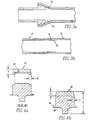
- the blood pump 10 comprises a blood pump 12 having a blood transport port 14 and a cannulae 16 connected to the port 14.
- the blood pump device 10 also comprises a coating material 18 covering the junction between the inner surfaces of the port 14 and cannulae 16 so that a smooth transition surface 20 is formed and blood can flow smoothly therefrom and collection cavities for the blood are eliminated.
- the inlet cannulae 16 can be inserted into the left atrium of the patient 22 and fixed with a double purse string suture.
- the outlet cannulae 15 can be sewn to the aorta of the patient 22.
- the inner junctions of the cannulae 15, 16 are coated with a polyurethane coating material 18 such as Biomer, manufactured by Ethicon, Inc.
- the coating material 18 provides a smooth transition surface 20 for the blood to flow on. This uniform transition is essential for reduction of clot formation.
- this coating material 18 is novel. It involves applying the polyurethane material 18 to the collection cavity 93 at the cannulae/port internal interface with a needle and syringe. After the polyurethane 18 is deposited, it is distributed evenly by hand rotation of the housing.
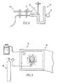
- the upper housing 26 is spun axially for each cannula 15, 16 in a motor driven coating chamber 92 for 24 hours.
- This promotes more uniform distribution of the polyurethane 18 and allows full curing. It also assures that the polyurethane coating 18 fills the step-off between the housing ports and the cannulae.
- the coating chamber 92 consists of a motor shaft 94 enclosed by a plexiglass box 96.
- the shaft 94 is connected to a variable speed motor 95 protruding through the rear of the box. Nitrogen is passed through a jig 97 which fastens to the motor 95 and holds the pump housing 26 and cannulae 15, 16.
- the jig 97 directs nitrogen from container 98 to pass over the junction being coated.
- the nitrogen carries away the solvent gases from the polyurethane 18 that would otherwise attack and degrade other areas of the pump housing 26.
- the custom jig 97 functions to hold the top housing 26 in both configurations, one for coating the inlet flow cannulae 15 and the other for coating the outlet flow cannulae 17. Once the polyurethane 18 is cured and evenly distributed, the housing 26 is removed and the process is repeated for the other cannula.
- a prior art pump without the coating technique forms a collection cavity 93.
- the prior art blood pump was implanted in 14 sheep in an experiment from December 1988 to October 1990. (Modified Fabrication Techniques Lead to Improved Centrifugal Blood Pump Performance, John J. Pacella et al., presented at the 40th Anniversary Meeting of the American Society for Artificial Internal Organs, San Francisco, California, April 1994).
- the pump was arranged extracorporeally in a left atrial to descending aortic cannulation scheme and the animals survived up to 13 days with the implanted prior art device.
- the blood pump device 10 comprises a first portion 28 having a chamber 30 and an inlet and outlet port 13, 14 in fluidic communication with the chamber 30.
- the blood pump device 10 also comprises a second portion 32 having a stator mechanism 34 and a rotor mechanism 36 disposed adjacent to and driven by the stator mechanism 34. Together, the stator mechanism 34 and the rotor mechanism 36 form the motor 888.
- the motor 888 is a brushless DC motor (BLDC) 888.
- the second portion 32 has a journal 38 disposed about the rotor mechanism 36 to provide support therewith.
- the second portion 32 also has an impeller 40 disposed in the chamber 30 and a one-piece seal member 42 for sealing about a shaft of the impeller 40.
- the seal member 42 is fixedly attached to the journal 38, such as with adhesive, so that the seal member 42 is supported by the journal 38.
- the seal member 42 comprises a coating surrounding and sealing its outer surface.
- the rotor 36 preferably has a surface 44 which has been polished to a surface finish of less than 2.54 ⁇ m for enhanced low friction operation. The amount of material removed from the rotor 36 during the polishing process is less than 2,54 ⁇ m (0.0001 inches).
- the hard plastic journal 38 and seal member 42 is fastened together, such as with Loctite 401 adhesive, to achieve seal stiffness, which was previously provided by the metal insert 45 molded into the prior seal 43.
- the seal member 42 can be coated with Biomer (Ethicon, Inc.) polyurethane for enhanced antithrombogenicity.
- the overall height, E, of the journal/seal assembly has been increased from approximately 23,57 mm to 23,98 mm (0.928 inches to 0.944 inches). This has resulted in a tighter seal at the junction between the outer rim 49 of the seal member 42 and the top housing 26, decreasing the chance for blood stasis and clot formation.
- the increased journal/seal height allows this compression to occur closer to the beginning of the threads. In other words, the upper housing does not need to be rotated as far through the threads to achieve the same tightness as it would if the journal/seal height, E, was not increased. Because of this, there is more room to achieve a tighter seal.
- the top edge 50 of the rotor post 46 is preferably rounded to allow a better fit under the seal member 42.
- the rotor post 46 is inserted into the journal 38 and fits just beneath the seal member 4 2 .
- the junction between the journal 38 and the seal member 46 occurs at this point and the two components are affixed with adhesive (i.e. Loctite 401).
- the rounding of the edge 50 on the rotor post 46 prevents the rotor 36 from rubbing against any excess glue that may be present after the seal member 42 and journal 38 are fastened together.
- the surfaces of the rotor 36 are preferably polished to 2.54 ⁇ m and given a rust-proof coating 58. Results from the sheep studies have revealed little evidence of rust and polished surfaces have been shown to greatly increase durability between the rotor 36 and journal 38 and between the rotor 56 and the lower housing 60.
- the infusion port 62 is preferably enlarged from 0,76 mm to 1.57 mm (0.03 inches to 0.062 inches).
- the housing 24 and port 62 can also be cryogenically deburred.
- a 1/4 28 UNF male luer lock 66 is used instead of the prior 1/4 28 UNF threaded hex barb 68 to eliminate the male-female junction 64 at this point.
- the port 62 serves as a passageway for pump lubricant, such as water or saline, which is delivered to the pump and exits through the rubber seal member 42 into the blood stream.
- the port 62 is enlarged because it assists in attaining lower pump lubricant pressures, which diminishes the stress on all lubricant system components. Also, a small port is more likely to become occluded with debris (e.g. salt deposit from lubricant saline solution) and cause increases in lubricant pressures.
- the male-female junction 64 in the previous design was eliminated to decrease the chance of foreign debris in the chest cavity from infiltrating into the lubricant system.
- the use of a threaded barb 66 helps to solve this problem because there is one less junction.
- the threaded end is screwed into the lower housing 60 and chemically sealed and the barbed end is inserted directly into the lubricant tubing 69 creating a mechanical seal.
- the deburring of the housing 60 results in increased durability and improved pump performance and lower internal lubricant temperatures.
- the internal lubricant temperature was measured by inserting an Omega, Inc 33 Gauge hypodermic needle thermocouple directly through the pump baffle seal, just below the lip of the seal where the lubricant passes out.
- the lubricant temperatures of a pump device 10 with polished, deburred components was found to be 42-43°C, which is significantly less. Since heat is thought to be a possible contributor to thrombus formation, this may have increased the antithrombogenicity of the pump as well as increasing its durability.
- a new mold 70 was designed for stator fabrication.
- New, thermally conductive epoxy material is used for fabricating the stator 34.
- the new mold 70 has two halves 72, 74, a removable center stem 76 and handles 78 for quick releasing of the halves 72, 74.
- Fastening bolts 80 hold the halves 72, 74 and center stem 76 together.
- the mold 70 has significantly increased the quality of the stator 34 as indicated by the progressive increases in the survival times of sheep in the disclosed blood pump implantation studies. In chronological order, the five studies of durations greater than ten days were 14, 10, 28, 35, and 154 day durations. The new mold 70 was used in the 35 and 154 day studies.
- Thermally conductive epoxy material was used for stator fabrication to help carry heat away from the stator 34 ana allow it to conduct readily to the surrounding tissues.
- the present stator 34 with thermally conductive epoxy has surface temperatures rarely exceeding 2.5°C above ambient temperature versus 5-7 C in the 14 and 10 day studies.
- environmentally sealed connectors 72 replace older style connectors used for controller/stator electrical connections.
- the stator 34 can be dip coated in polyurethane before potting.
- a commercially available environmentally sealed connector 72 (LEMO USA, Inc.) is preferably used to prevent the electrical connections from failing in the event of exposure to fluid.
- the prior art connector was not waterproof. To hermetically seal the stator 34, it can be dipped in polyurethane several times during the fabrication process.
- Figures 12a and 12b show the prior art stator and the stator 34 of the present pump device 10.
- the control means 80 of the present invention preferably has an output 82 for actuation of a safety occluder device 83 in the event of motor failure. Also, there are standardized outputs for current 84, speed 86, and lubricant system pressure 88 (0-1 Volt).
- the controller 80 uses isolated circuitry to cut down on noise by stator commutation. Three meters 90 of a display means 81, with both digital and bar graph output show the outputs.
- the automated occluder initiation output 82 greatly enhances safety for in vivo use of the blood pump.
- the controller 80 will activate the safety occluder device 83 to prevent retrograde pump flow through the cannulae 16. If pump current becomes zero, the controller 80 will attempt to restart the pump five times and if it is unsuccessful, it will send a signal to actuate the occluder device 83 through output 82.
- the increased reliability allows more time for intervention and troubleshooting.
- the standardized analog outputs for current 84, speed 86, and perfusion pressure 88 (0-1 volt) provides enhanced and comprehensive data collection.
- the outputs 84, 86, 88 can be used for trend recording on a strip chart recorder 94, as opposed to direct measurements once a day. Furthermore, isolated circuitry and display means 89 with three meters 90 with both digital and bar graph output with ⁇ 1% accuracy on all readings prevent noise caused by stator commutation and provides reliable data collection.
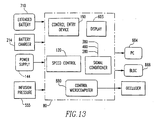
- the controller in more detail is shown in figure 13.
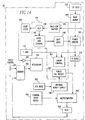
- the sensorless blood pump controller 80 is preferably used to control the motor 888. It is called sensorless because no sensors are disposed in the pump 12 itself. Referring to figure 14, a block diagram is provided of the preferred embodiment of many possible embodiments of the sensorless blood pump controller 80.
- a highly integrated control I.C. 170 such as ML4411 available from Microlinear, San Jose, CA., is comprised of the VCO 130 connected to a Back-Emf sampler 230 and to a logic and control 140.
- the control I.C. 170 also includes gate drivers 240 for connection to power driver 260, linear control 901 connected to power driver 260 and I limit 110 and integrator 101 and R sense 270.
- the control I.C. 170 additionally includes power fail detect 160.
- the ML4411 I.C. 170 provides commutation for the BLDC motor 888 utilizing a sensorless technology to determine the proper phase angle for the phase locked loop.
- the function and operation of the specific features and elements of the control I.C. 170 itself is well known in the art. Motor commutation is detected by the Back-EMF sampler 230.
- loop filter 900 For closed loop control, loop filter 900, connected to VCO 130 and amplifier 290, charges on late commutation, discharges on early commutation and is buffered by a non-inverting amplifier 290, model LM324 available from National Semiconductor, Santa Clara, CA.
- the buffered output provides feedback to the integrator 101 that includes an inverting amplifier, model LM324.
- non-inverting amplifier 290 and integrator 101 with an inverting amplifier are disposed on one chip.
- the speed control 120 uses a 20K ohm dailpot, model 3600S-001-203 available from BOURNS, Riverside, CA.
- the speed control 120 in conjunction with summer 700 provides the set point for integrator 101.
- the output from the integrator 101 is used in conjunction with the input from R Sense 270, .05 ohms, part number MP821-.05, available from Caddock Electronics, Riverside, CA, to the linear control 901 to modulate gate drivers 240.
- the power drivers 260 consists of six N- channel field effect transistors, part number RFP70N03, available from Harris Semiconductor, Melbourne, Fl.
- the power drivers 260 connected to the gate drivers 240, drive the BLDC motor 888.
- the integrator 101 receives the desired speed control from the speed control 120 and also receives a feedback signal from the control I.C. 170 through its Back-EMF sampler 23 which passes the speed of the rotor 36 in the BLDC motor 888.
- the output signal from the integrator 101 which essentially is an error correction signal corresponding to the difference between the speed control set point signal and the sensed velocity of the rotor mechanism 36 of the BLDC motor 888, is provided to the linear control 901.
- the linear control 901 with the error correction voltage signal from the integrator 101 and the voltage signal from the R sense 270, which corresponds to the stator mechanism 34 current, modulates the gate drivers 240 to ultimately control the current to the stator mechanism 34 of the DC motor 888.
- the R sense 270 is in series with the power drivers 260 to detect the current flowing through the power drivers 260 to the stator mechanism 34 windings of the BLDC motor 888.
- Power fail detect 160 an open collector output from the ML4411 control I.C. 170, is active when the +12VDC or the +5VDC from the power supply 180 is under-voltage.
- the power fail detect 160 alerts the microcomputer 880 that a fault condition exists.
- external power supply 144 provides 12 VDC for the sensorless controller 80. Switching the external power supply 144 on or off is accomplished by the on/off control entry microcomputer 800. A logic '1' gates the external power supply 1 off and vice-versa. Battery back-Up is accomplished by solid state relay 777, P.N. AQV210, available from AROMAT, New Buffalo, NJ.
- the internal power supply 180 P.N V1-J01-CY, available from Vicor, Andover, MA is enabled.
- the internal power supply 180 which derives power from the battery 490 P.N. V1-J01-CY, available from Vicor, Andover, MA is enabled.
- the internal power supply 180 derives power from the battery 490 P.N.
- power is derived from the 12V Buss 250 and feeds DC to DC converter 410, P.N. NME1212S, available from International Power Sources, Ashland, MA and provides +12,-12V for the Analog circuitry.
- the DC/DC converter 820, P.N. 78SR105 available from Power Trends, Batavia, IL provides +5 VDC power for the DVM's and the control I.C. 170.
- the DC/DC converter 122, P.N. 11450, available from Toko America, Prospect, IL provides +5VDC to the microcomputer 880.
- the control entry computer 800 toggles an I/O line to signal the External Power Supply 144 to power up and to turn status indicator 222 on.
- the START, RESET, and MUTE lines from 190 are connected to resistor pack 480 P.N. R-9103-10K, available from Panasonic, Secacus, N.J.
- the control entry microcomputer 800 sends control lines including START, RESET, and MUTE to the control microcomputer 880, P.N. PIC16C71, available from Microchip, San Jose, CA and to the Status Indicators 222, P.N. 16.921-08, available from Solic/MEC, Hartford, CT. Depressing the START on control entry device 190 causes the Control Entry microcomputer 800, to assert the START signal to Control microcomputer 880.
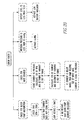
- the Control microcomputer 880 initiates the sequence to start the motor 888. Refer to figure 18.
- the control microcomputer 880 digitizes three analog inputs including current conditioner 460 connected to the motor 888, Infusion Pressure conditioner 280 and the internal battery voltage 490.
- the Control I.C. 170 is connected to the RPM conditioner 380.
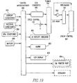
- the control microcomputer 880 is connected to the RPM conditioner 380. Referring to figure 18, the control microcomputer 880 measures the period of the RPM input and calculates the RPM. Referring to figure 19, the control microcomputer 880 updates the LCD Display 603, P.N. 97-20947-0, available from EPSON, Terrance, CA and downloads the data including RPM, current, infusion pressure, and battery voltage to the external connection connecting the SBPC to the IBM printer port 604.
- the control microcomputer 880 is connected to the alarm 602, P.N. P9923, available from Panasonic, Secaucus, N.J. and is activated when the infusion pressure is low. See figure 20.
- the control microprocessor 880 of figure 19 Upon an error detected with the retrograde flow, the control microprocessor 880 of figure 19, outputs ramped voltage to the digital to analog converter 500, P.N. MAX531, available from Maxim, Sunnyvale, CA.
- the D/A converter 500 is connected to an analog summer 700.
- the speed control 120 is connected to the analog summer 700, which is part of four amplifiers in a package. P.N. LM324, available from national semiconductor, Santa Clara, CA.
- the summer 700 is connected to the integrator 101.
- the integrator 101 is connected to the control I.C. 170.
- control microcontroller 880 upon detecting an error that RPM is less than 2000 or zero motor current tries to restart the motor 888 five times. After five times, if the motor 888 does not start, then the SBPC activates an external occluder.
- the surfaces of the internal pump components have been treated in order to minimize friction. These treatments include polishing, ion deposition, and cryogenic deburring.
- the pump device 10 has demonstrated efficacy in five chronic sheep implantation studies of 10, 14, 28, 35 and 113+ day durations. Post-mortem findings of the 14-day experiment revealed stable fibrin entangled around the impeller shaft and blades. Following pump modification with refined coating techniques and advanced impeller materials, autopsy findings of the ten-day study showed no evidence of clot. Additionally, the results of the 28-day experiment showed only a small (2.0 mm) ring of fibrin at the shaft-seal interface. In this study, however, the pump failed on day 28 due to erosion of the stator epoxy.
- the pump device 10 was implanted in five sheep for a minimum of 10 days. Prior to surgery, the sheep were fasted for 24 hours, but were allowed unlimited access to water. The pump device 10 was implanted through a left thoracotomy and arranged in a left atrial-to-descending aortic cannulation scheme.
- Two percutaneous tubes were required for pump operation: one was used to jacket the conductors that supply power to the stator 34 and the other provided a conduit for pump lubricant infusion.
- the animals were infused at a constant rate with either 0.9% saline or sterile water as the pump lubricant.
- Daily measurements of pump speed, current, voltage, flow, animal body temperature, and stator surface temperature were obtained.
- the animals were free to ambulate within a 4-foot by 6-foot pen and were tethered to a custom-made swivel tether device as disclosed in U.S. Patent No. 5,305,712.
- Weekly blood draws consisted of blood counts, electrolytes, coagulation profiles, hepatic and renal function, and hemolysis. Blood cultures were obtained as needed.
- the autopsy included complete histopathologic studies and a microscopic analysis of the pump 10.
- the 14-day study incorporated a prior art rotor and lower housing, a polysulfone impeller, and a polyurethane coating applied to the cannulae/housing interfaces.
- the lubricant flow rate was 2 ml/hr and no anticoagulants were used.
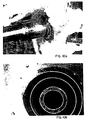
- Autopsy findings revealed a massive clot entangled within the impeller blades and fixed to the impeller shaft at the shaft/seal junction, as shown in figure 10a.
- the cannulae/housing interfaces were free to clot due to the sealing material 18. Rust was present on the rotor, as shown in figure 11a.
- the second study of 10 days duration included pump alterations consisting of a polyurethane coating (Biomer, Ethicon, Inc.) applied to the seal 42, a pyrolytic carbon impeller 40, a 0.9% saline lubricant flow rate of 4 ml/hr, and the use of heparin in the saline lubricant. Streptokinase was administered every third day with the lubricant. The explanted pump was found completely devoid of thrombus, as shown in figure 10b.
- the pump was arranged similarly to the 10-day study.
- the lubricant flow rate was increased to 10 ml/hr and 325 mg aspirin and 5-20 mg coumadin were given daily by mouth to broaden the anticoagulant regimen.
- a 2 mm ring thrombus was found at the impeller shaft/seal interface, as shown in figure 10c, and the motor was found to be contaminated by chest cavity fluid as indicated by chemical corrosion of select stator windings.
- the fourth study of 35 days used several of the new pump components. These comprised a stator 34 with several polyurethane coatings and an increased epoxy potting thickness to prevent fluid corrosion, as shown in figure 12b. Also, a thin layer of titanium ion-coating was used to passivate the rotor surfaces 46 and reduce the opportunity for rust formation. Furthermore, the lower housing bearing surface was deburred to decrease wear on the rotor 36. The perfusion flow rate and anticoagulation scheme remained unaltered in this study.
- the explanted pump had a small irregular ring clot of 0.5 mm at its widest point surrounding the impeller shaft/seal junction. The pump lubricant system became completely occluded due to precipitation of salt from the saline solution. As a result, significant seepage of blood products below the seal caused increased friction between the rotor 36 and its bearing surfaces and eventually caused pump stoppage. However, there were no emboli at autopsy.
- the last study of 154 days duration included variations from the previous study. For instance, thin layer chromium ion-coating was used in place of titanium coating to passivate the rotor 36 because it was available and cheaper.
- the lubricant was changed from 0.9% saline to sterile water on post-operative day (POD) 86 in order to reduce the chance of lubricant system occlusion due to salt precipitation.
- POD post-operative day
- urokinase was used as an alternative to streptokinase beginning on POD 130 because of its suspected superior thrombolytic effect.
- the lubricant rate was increased from 2 to 10 ml/hr over the course of the five studies. The intention was to increase fluid washing of the seal/impeller shaft interface to prevent blood stasis and thrombus formation.
- Precipitated salt was identified as a potential source of lubricant blockage in the 35-day study.
- the 154-day study underwent a change in lubricant from 0.9% saline to sterile water. The hematocrit and serum free hemoglobin measures were unaffected by this change.
- the novel construction of the pump device 10 contributed to overall improved pump performance as compared to previous pump devices. Conditioning of both the rotor 36 and lower housing surfaces has included polishing and passivating and cryogenic deburring, respectively. These techniques provide even distribution of lubricant over the moving components, smoother surfaces for direct contact in the event of lubricant system failure, and resistance to the oxidation of iron. These studies show that passivation of the rotor surfaces caused elimination of rotor rust, as evidenced by a comparison of the prior art rotor used in the 14-day study (figure 11a) with the chromium-coated rotor used in the 154-day study (figure 11b).
- the decreases in temperature difference between the stator and ambient can be related to increases in lubricant flow rate from 2 to 10 ml/hr (Table II). Based on these five studies, the implications are that the temperature difference between the stator surface and ambient decreased by means of increased convective heat loss through higher lubricant infusion rates.
- the polyurethane coatings have contributed significantly to the antithrombogenicity of the pump. Specifically, the application of polyurethane material 18 to the cannulae/housing interface has had striking results: no clots have been found in any of the five studies at this juncture, nor have they been found in 39 other accumulated implantation studies. This has been a major improvement of the present pump device 10 based on prior studies (Goldstein, A.H., Pacella, J.J., Trumble, D.R., et al.: Development of an implantable centrifugal blood pump. ASAIO Trans 38:M362-M365, 1992).
Landscapes
- Health & Medical Sciences (AREA)
- Heart & Thoracic Surgery (AREA)
- Engineering & Computer Science (AREA)
- Cardiology (AREA)
- Hematology (AREA)
- Mechanical Engineering (AREA)
- Anesthesiology (AREA)
- Biomedical Technology (AREA)
- Life Sciences & Earth Sciences (AREA)
- Animal Behavior & Ethology (AREA)
- General Health & Medical Sciences (AREA)
- Public Health (AREA)
- Veterinary Medicine (AREA)
- Vascular Medicine (AREA)
- External Artificial Organs (AREA)
- Structures Of Non-Positive Displacement Pumps (AREA)
Description
| Result Dependent Modifications | |||||
| Experiment Duration (Days) | |||||
| | 14 | 10 | 28 | 35 | 154 |
| Lower Housing Conditioning | X | X | |||
| Rotor Conditioning | X | X | |||
| Re-designed Stator | X | X | |||
| Seal Coating | X | X | X | X | |
| Cannula/Housing Coating | X | X | X | X | X |
| Impeller Material | P | C | C1 | C1 | C1 |
| Perfusion Flow Rate (ml/hr) | 2 | 4 | 10 | 10 | 10 |
| 2Anticoagulation | N | H,S | A,H,C,S | A,H,C,S | A,H,C,S,U |
| Average: Values of Pump Efficiency, Stator Temperature, Animal Temperature, and Temperature Difference for Each Study | |||||
| Study Duration (days) | 14 | 10 | 28 | 35 | 154 |
| Pump Efficiency (%) | 13.6±2.1 | 16.3±4.7 | 20.5±2.6 | 15.0±1.6 | 13.2±2.2 |
| Stator Temp. (°C) | 45.4±1.4 | 44.8±1.4 | 41.8±0.7 | 41.5±0.7 | 41.6±1.0 |
| Animal Temp. (°C) | 39.2±0.3 | 39.0 | 40.6±0.7 | 39.0±0.7 | 39.1±0.6 |
| Temperature Difference (°) | 6.8±1.5 | 5.8±1.4 | 1.3±0.7 | 2.4±0.5 | 2.6±0.6 |
Claims (9)
- A blood pump device (10) comprising:characterised in that the blood pump device (10) further comprisesa blood pump (12) for implantation in a patient (22) ;an inlet cannula (15) connected to the blood pump (12) and for connection to a patient's circulatory system through which blood of the patient (22) passes to the blood pump (12) and is pumped when the blood pump (12) is implanted in the patient (22);an outlet cannula (16) connected to the blood pump (12) and for connection to the patient's circulatory system through which blood of the patient (22) passing from the blood pump (12) when the blood pump (12) is implanted in the patient (22);means for providing power to the blood pump (12) so that blood can be pumped through the outlet cannula (16) that is received from the inlet cannula (15), said providing means comprising a controller (80) having means for sensing pump failure,
a safety occluder device (83) disposed about the outlet cannula (16), said blood pump (12), cannulae and safety occluder device (83) together for implantation into the chest of the patient (22); and in that
the controller (80) has an output terminal (82) for actuating the safety occluder device (83) in an event of pump failure so that the safety occluder device (83) prevents retrograde pump flow through the outlet cannula (16), said safety occluder device (83) in communication with the output terminal (82). - A device (10) as described in claim 1
characterized by the fact that the blood pump (12) comprises a motor (88) having stator mechanism (34) and a rotor mechanism (36) driven by the stator mechanism (34), said sensing means (92) comprises means (92) for determining back electromagnetic force within the stator mechanism (34). - A device (10) as described in claim 2
characterized by the fact that said controlling means (80) having means for providing signals indicate of stator current (84) and rotor speed (86), respectively, said providing means in communication with the means (92) for determining back electromagnetic force in the stator mechanism (34). - A device (10) as described in claim 3
characterized by means for supplying lubricant to the motor, said supplying means in fluidic communication with the blood pump (12), said controlling means (80) having means for measuring lubricant pressure. - A device (10) as described in claim 4
characterized by the fact that the power providing means comprises a modular driver unit remote from said pump (12) and in communication therewith. - A device (10) as described in claim 5
characterized by the fact that the controlling means (80) comprises means for adjusting speed of the motor mechanism with a better than 5% accuracy. - A device (10) as described in claim 6
characterized by the fact that the controlling means (80) comprises a display mechanism for providing values of stator current (84) rotor speed (86) and lubricant pressure (88). - A device (10) as described in Claim 7
characterized by the fact that said occluder device (83) is disposed about the outlet cannulae (16) and does not obstruct blood flow in the patient (22) when the occluder device (83) is in a non-activated state, and the occluder device (83) prevents retrograde blood flow through the outlet cannulae (16) in the activated state by closing the outlet cannulae (16). - A method for pumping blood of a patient (22) , the method comprising the steps of:implanting a blood pump (12) having an inlet cannula (15) and an outlet cannula (16) connected to it into a patient;pumping blood in the patient (22) which is received through the inlet cannula (15) connected to the blood pump (12) and out through the outlet cannula (16) connected to the blood pump (12);sensing with a controller (80) having a mechanism for sensing pump failure, characterised in that the method further comprises the steps of:implanting a safety occluder device (83) connected to the outlet cannula (16) into the patient (22);activating the safety occluder device (83) whether the blood pump (12) is working properly; andactivating the safety occluder device (83) connected to the outlet cannula (16) with the controller (80) if the blood pump (12) stops working properly so blood will not flow back into the outlet cannula (16).
Priority Applications (1)
| Application Number | Priority Date | Filing Date | Title |
|---|---|---|---|
| EP03027554A EP1402908A3 (en) | 1994-04-15 | 1995-04-13 | Blood pump device and method of producing |
Applications Claiming Priority (3)
| Application Number | Priority Date | Filing Date | Title |
|---|---|---|---|
| US22843394A | 1994-04-15 | 1994-04-15 | |
| US228433 | 1994-04-15 | ||
| PCT/US1995/004597 WO1995028185A1 (en) | 1994-04-15 | 1995-04-13 | Blood pump device and method of producing |
Related Child Applications (1)
| Application Number | Title | Priority Date | Filing Date |
|---|---|---|---|
| EP03027554A Division EP1402908A3 (en) | 1994-04-15 | 1995-04-13 | Blood pump device and method of producing |
Publications (3)
| Publication Number | Publication Date |
|---|---|
| EP0708664A1 EP0708664A1 (en) | 1996-05-01 |
| EP0708664A4 EP0708664A4 (en) | 1999-01-20 |
| EP0708664B1 true EP0708664B1 (en) | 2004-01-02 |
Family
ID=22857152
Family Applications (2)
| Application Number | Title | Priority Date | Filing Date |
|---|---|---|---|
| EP03027554A Withdrawn EP1402908A3 (en) | 1994-04-15 | 1995-04-13 | Blood pump device and method of producing |
| EP95916382A Expired - Lifetime EP0708664B1 (en) | 1994-04-15 | 1995-04-13 | Blood pump device and method for pumping blood of a patient |
Family Applications Before (1)
| Application Number | Title | Priority Date | Filing Date |
|---|---|---|---|
| EP03027554A Withdrawn EP1402908A3 (en) | 1994-04-15 | 1995-04-13 | Blood pump device and method of producing |
Country Status (8)
| Country | Link |
|---|---|
| US (2) | US5711753A (en) |
| EP (2) | EP1402908A3 (en) |
| JP (2) | JP3920326B2 (en) |
| AU (2) | AU699959B2 (en) |
| CA (2) | CA2165166C (en) |
| DE (1) | DE69532372T2 (en) |
| ES (1) | ES2213752T3 (en) |
| WO (1) | WO1995028185A1 (en) |
Families Citing this family (50)
| Publication number | Priority date | Publication date | Assignee | Title |
|---|---|---|---|---|
| US6129660A (en) * | 1995-08-23 | 2000-10-10 | Ntn Corporation | Method of controlling blood pump |
| ES2227718T3 (en) * | 1996-10-04 | 2005-04-01 | United States Surgical Corporation | CIRCULATORY SUPPORT SYSTEM. |
| EP0946222A1 (en) * | 1996-12-13 | 1999-10-06 | Data Sciences International, Inc. | Biocompatible medical devices with polyurethane surface |
| WO1999004834A1 (en) * | 1997-07-25 | 1999-02-04 | Sun Medical Technology Research Corporation | Portable drive system for artificial heart |
| EP1019117B2 (en) * | 1997-10-02 | 2015-03-18 | Micromed Technology, Inc. | Controller module for implantable pump system |
| US6889082B2 (en) | 1997-10-09 | 2005-05-03 | Orqis Medical Corporation | Implantable heart assist system and method of applying same |
| US7138776B1 (en) | 1999-07-08 | 2006-11-21 | Heartware, Inc. | Method and apparatus for controlling brushless DC motors in implantable medical devices |
| AU6353900A (en) * | 1999-07-29 | 2001-02-19 | Sysflow Medical, Inc. | Blood treatment system providing pulsatile flow and method of use |
| US7022100B1 (en) | 1999-09-03 | 2006-04-04 | A-Med Systems, Inc. | Guidable intravascular blood pump and related methods |
| US6306116B1 (en) * | 1999-09-30 | 2001-10-23 | Origin Medsystems, Inc. | Method and apparatus for pressurizing the right atrium or right ventricle to assist cardiac function during beating heart surgery |
| JP5214836B2 (en) * | 2000-03-27 | 2013-06-19 | ザ クリーブランド クリニック ファウンデーション | Long-term performance control system for turbo blood pump |
| US6530876B1 (en) | 2000-04-25 | 2003-03-11 | Paul A. Spence | Supplemental heart pump methods and systems for supplementing blood through the heart |
| US6808508B1 (en) * | 2000-09-13 | 2004-10-26 | Cardiacassist, Inc. | Method and system for closed chest blood flow support |
| EP1369788A3 (en) | 2002-06-04 | 2007-07-04 | Bayer HealthCare LLC | RS232C interface system |
| US7488448B2 (en) * | 2004-03-01 | 2009-02-10 | Indian Wells Medical, Inc. | Method and apparatus for removal of gas bubbles from blood |
| US7273446B2 (en) * | 2003-10-31 | 2007-09-25 | Spence Paul A | Methods, devices and systems for counterpulsation of blood flow to and from the circulatory system |
| ATE464479T1 (en) | 2005-12-01 | 2010-04-15 | Michigan Critical Care Consult | VENTRICULAR IMPULSE ROTARY PUMP |
| US8550973B2 (en) * | 2006-01-09 | 2013-10-08 | Cardiacassist, Inc. | Percutaneous right ventricular assist apparatus and method |
| US8672611B2 (en) | 2006-01-13 | 2014-03-18 | Heartware, Inc. | Stabilizing drive for contactless rotary blood pump impeller |
| JP5155186B2 (en) | 2006-01-13 | 2013-02-27 | ハートウェア、インコーポレイテッド | Rotary blood pump |
| EP1981585B1 (en) * | 2006-01-27 | 2019-03-06 | CircuLite, Inc. | Heart assist system |
| US7883451B2 (en) * | 2006-04-14 | 2011-02-08 | Treadwell Corporation | Methods of applying treadle stimulus |
| US8333686B2 (en) * | 2006-08-30 | 2012-12-18 | Circulite, Inc. | Cannula insertion devices, systems, and methods including a compressible member |
| US7905823B2 (en) * | 2006-08-30 | 2011-03-15 | Circulite, Inc. | Devices, methods and systems for establishing supplemental blood flow in the circulatory system |
| JP5537939B2 (en) * | 2006-08-30 | 2014-07-02 | サーキュライト・インコーポレーテッド | Apparatus, method and system for establishing supplemental blood flow in the circulatory system |
| JP5457182B2 (en) * | 2006-09-14 | 2014-04-02 | サーキュライト・インコーポレーテッド | Intravascular blood pump and catheter |
| EP2170449B1 (en) * | 2007-07-19 | 2013-01-16 | CircuLite, Inc. | Cannula for heart chamber implantation and related systems and methods |
| US8343029B2 (en) * | 2007-10-24 | 2013-01-01 | Circulite, Inc. | Transseptal cannula, tip, delivery system, and method |
| ATE556729T1 (en) * | 2008-08-05 | 2012-05-15 | Michigan Critical Care Consultants Inc | APPARATUS AND METHOD FOR MONITORING AND CONTROLLING EXTRACORPOREAL BLOOD FLOW RELATIVE TO A PATIENT'S FLUID STATUS |
| US8460168B2 (en) * | 2009-03-27 | 2013-06-11 | Circulite, Inc. | Transseptal cannula device, coaxial balloon delivery device, and methods of using the same |
| US20100249491A1 (en) * | 2009-03-27 | 2010-09-30 | Circulite, Inc. | Two-piece transseptal cannula, delivery system, and method of delivery |
| US9782527B2 (en) | 2009-05-27 | 2017-10-10 | Tc1 Llc | Monitoring of redundant conductors |
| US20110112353A1 (en) * | 2009-11-09 | 2011-05-12 | Circulite, Inc. | Bifurcated outflow cannulae |
| US8562519B2 (en) | 2009-12-31 | 2013-10-22 | Cardiacassist, Inc. | Pumping system and method for assisting a patient's heart |
| TW201217010A (en) | 2010-06-22 | 2012-05-01 | Thoratec Corp | Apparatus and method for modifying pressure-flow characteristics of a pump |
| US8905910B2 (en) | 2010-06-22 | 2014-12-09 | Thoratec Corporation | Fluid delivery system and method for monitoring fluid delivery system |
| USD669585S1 (en) | 2010-08-20 | 2012-10-23 | Thoratec Corporation | Implantable blood pump |
| EP2613821B1 (en) | 2010-09-07 | 2023-02-15 | Paul A. Spence | Cannula systems |
| KR102109391B1 (en) | 2011-11-28 | 2020-05-13 | 미-바드, 아이엔씨. | Ventricular assist device and method |
| EP2908880B1 (en) | 2012-10-16 | 2018-12-05 | Paul A. Spence | Devices for facilitating flow from the heart to a blood pump |
| EP3076884B1 (en) | 2013-12-04 | 2020-02-05 | Heartware, Inc. | Apparatus for cutting an atrial wall |
| EP3110468B1 (en) | 2014-02-25 | 2021-11-03 | Kushwaha, Sudhir | Ventricular assist device and method |
| WO2015139031A1 (en) | 2014-03-14 | 2015-09-17 | Cardiac Assist, Inc. | Image-guided transseptal puncture device |
| US10426879B2 (en) * | 2015-12-14 | 2019-10-01 | Heartware, Inc. | Blood pump with restart lockout |
| WO2017117185A1 (en) | 2015-12-28 | 2017-07-06 | Heartware, Inc. | Pump motor control with adaptive startup |
| US10857273B2 (en) | 2016-07-21 | 2020-12-08 | Tc1 Llc | Rotary seal for cantilevered rotor pump and methods for axial flow blood pumping |
| WO2018031741A1 (en) | 2016-08-12 | 2018-02-15 | Tc1 Llc | Devices and methods for monitoring bearing and seal performance |
| WO2019036206A1 (en) * | 2017-08-18 | 2019-02-21 | Heartware, Inc. | Therapeutic uv blood treatment in a blood pump |
| WO2021222403A1 (en) * | 2020-04-28 | 2021-11-04 | Shifamed Holdings, Llc | Intravascular blood pumps and control thereof |
| CN115227964B (en) * | 2022-09-21 | 2022-12-27 | 深圳核心医疗科技有限公司 | Flow velocity control method and device |
Family Cites Families (20)
| Publication number | Priority date | Publication date | Assignee | Title |
|---|---|---|---|---|
| US3457909A (en) * | 1966-07-20 | 1969-07-29 | Avco Corp | Heart augmentation system provided with means for measuring intra-arterial pressure |
| US3736930A (en) * | 1970-04-14 | 1973-06-05 | Ivac Corp | Parenteral administration fluid flow control system |
| US3731679A (en) * | 1970-10-19 | 1973-05-08 | Sherwood Medical Ind Inc | Infusion system |
| US3791773A (en) * | 1972-06-09 | 1974-02-12 | Little Giant Corp | Submersible pump |
| DE2535650C2 (en) * | 1975-08-09 | 1982-05-27 | Dr. Eduard Fresenius, Chemisch-pharmazeutische Industrie KG Apparatebau KG, 6380 Bad Homburg | Roller peristaltic pump with an electric drive motor |
| US4024864A (en) * | 1975-09-05 | 1977-05-24 | Cordis Corporation | Injector with overspeed protector |
| US4222127A (en) * | 1978-06-02 | 1980-09-16 | Donachy And Pierce | Blood pump and method of pumping blood |
| DE3280274D1 (en) * | 1981-03-18 | 1991-01-31 | Guenther Walter Otto Bramm | DEVICE FOR PUMPING WITH A MAGNETICALLY SUSPENDED AND DRIVEN ROTOR. |
| EP0079373B1 (en) * | 1981-05-19 | 1986-12-30 | Thoratec Laboratories Corporation | Hydraulically actuated cardiac prosthesis |
| US5078741A (en) * | 1986-10-12 | 1992-01-07 | Life Extenders Corporation | Magnetically suspended and rotated rotor |
| JPH0411715Y2 (en) * | 1985-08-30 | 1992-03-24 | ||
| US4808167A (en) * | 1987-01-16 | 1989-02-28 | Pacesetter Infusion, Ltd. | Medication infusion system with disposable pump/battery cassette |
| US5089014A (en) * | 1987-05-18 | 1992-02-18 | Holfert John W | Tubular interconnect device for use within the circulatory system |
| US4927407A (en) * | 1989-06-19 | 1990-05-22 | Regents Of The University Of Minnesota | Cardiac assist pump with steady rate supply of fluid lubricant |
| US5188604A (en) * | 1989-09-29 | 1993-02-23 | Rocky Mountain Research, Inc. | Extra corporeal support system |
| US5267940A (en) * | 1989-11-29 | 1993-12-07 | The Administrators Of The Tulane Educational Fund | Cardiovascular flow enhancer and method of operation |
| US5118264A (en) * | 1990-01-11 | 1992-06-02 | The Cleveland Clinic Foundation | Purge flow control in rotary blood pumps |
| JPH05505321A (en) * | 1990-02-09 | 1993-08-12 | テラコール | Method and device for regulating flow rate in a cardiac prosthesis providing periodic flow |
| EP0518050B1 (en) * | 1991-05-10 | 1996-07-10 | Terumo Kabushiki Kaisha | Liquid pump apparatus |
| JPH0669492B2 (en) * | 1992-08-20 | 1994-09-07 | 日機装株式会社 | Blood pump |
-
1995
- 1995-04-13 CA CA002165166A patent/CA2165166C/en not_active Expired - Fee Related
- 1995-04-13 EP EP03027554A patent/EP1402908A3/en not_active Withdrawn
- 1995-04-13 JP JP52710095A patent/JP3920326B2/en not_active Expired - Fee Related
- 1995-04-13 WO PCT/US1995/004597 patent/WO1995028185A1/en active IP Right Grant
- 1995-04-13 DE DE69532372T patent/DE69532372T2/en not_active Expired - Lifetime
- 1995-04-13 EP EP95916382A patent/EP0708664B1/en not_active Expired - Lifetime
- 1995-04-13 CA CA002374746A patent/CA2374746C/en not_active Expired - Fee Related
- 1995-04-13 ES ES95916382T patent/ES2213752T3/en not_active Expired - Lifetime
- 1995-04-13 AU AU35134/95A patent/AU699959B2/en not_active Ceased
-
1996
- 1996-03-18 US US08/618,084 patent/US5711753A/en not_active Expired - Lifetime
-
1997
- 1997-07-21 US US08/898,584 patent/US6162167A/en not_active Expired - Lifetime
-
1998
- 1998-05-15 AU AU65997/98A patent/AU718838B2/en not_active Ceased
-
2006
- 2006-12-06 JP JP2006328961A patent/JP2007111544A/en active Pending
Also Published As
| Publication number | Publication date |
|---|---|
| CA2374746A1 (en) | 1995-10-26 |
| US6162167A (en) | 2000-12-19 |
| EP0708664A4 (en) | 1999-01-20 |
| JPH09502375A (en) | 1997-03-11 |
| EP0708664A1 (en) | 1996-05-01 |
| DE69532372T2 (en) | 2004-12-30 |
| EP1402908A2 (en) | 2004-03-31 |
| CA2374746C (en) | 2004-03-02 |
| AU6599798A (en) | 1998-07-02 |
| WO1995028185A1 (en) | 1995-10-26 |
| JP2007111544A (en) | 2007-05-10 |
| CA2165166A1 (en) | 1995-10-26 |
| CA2165166C (en) | 2002-12-17 |
| US5711753A (en) | 1998-01-27 |
| EP1402908A3 (en) | 2005-04-27 |
| JP3920326B2 (en) | 2007-05-30 |
| DE69532372D1 (en) | 2004-02-05 |
| ES2213752T3 (en) | 2004-09-01 |
| AU3513495A (en) | 1995-11-10 |
| AU699959B2 (en) | 1998-12-17 |
| AU718838B2 (en) | 2000-04-20 |
Similar Documents
| Publication | Publication Date | Title |
|---|---|---|
| EP0708664B1 (en) | Blood pump device and method for pumping blood of a patient | |
| US6808482B1 (en) | Blood pump device and method of producing | |
| US11185678B2 (en) | Blood pump | |
| Yamazaki et al. | EVAHEART™: An implantable centrifugal blood pump for long-term circulatory support | |
| EP0897476B1 (en) | Hybrid magnetically suspended and rotated centrifugal pumping apparatus and method | |
| US9616157B2 (en) | Blood pump | |
| AU678697B2 (en) | Cannula pumps for temporary cardiac support | |
| US5290227A (en) | Method of implanting blood pump in ascending aorta or main pulmonary artery | |
| US7238151B2 (en) | Permanent heart assist system | |
| JP2000512191A (en) | Intracardiac blood pump | |
| EP0478635A4 (en) | Cardiac assist pump | |
| Mizuguchi et al. | Development of an axial flow ventricular assist device: in vitro and in vivo evaluation | |
| Rowles et al. | Ventricular assist and total artificial heart devices for clinical use in 1993 | |
| Wakisaka et al. | Long‐Term Evaluation of a Nonpulsatile Mechanical Circulatory Support System | |
| IL114515A (en) | Blood pump device and method of producing it | |
| Savage et al. | The AB-180 circulatory support system: summary of development and plans for phase I clinical trial | |
| Minato et al. | A Seal‐less Centrifugal Pump (Baylor Gyro Pump) for Application to Long‐Term Circulatory Support | |
| Aber et al. | Development of the NASA/Baylor VAD | |
| Golding et al. | Centrifugal pumps—now and the future | |
| Bacak et al. | DEVELOPMENT OF THE NASA/BAYLOR VAD | |
| Akdis et al. | Mechanical blood pumps for cardiac assistance | |
| Pagani | Circulatory Support for Bridging to Recovery or Transplantation | |
| Wnek et al. | Cardiac Assist Devices/Keefe B. Manning, Conrad M. Zapanta, John M. Tarbell |
Legal Events
| Date | Code | Title | Description |
|---|---|---|---|
| PUAI | Public reference made under article 153(3) epc to a published international application that has entered the european phase |
Free format text: ORIGINAL CODE: 0009012 |
|
| 17P | Request for examination filed |
Effective date: 19960109 |
|
| AK | Designated contracting states |
Kind code of ref document: A1 Designated state(s): CH DE ES FR GB IE LI SE |
|
| A4 | Supplementary search report drawn up and despatched |
Effective date: 19981203 |
|
| AK | Designated contracting states |
Kind code of ref document: A4 Designated state(s): CH DE ES FR GB IE LI SE |
|
| 17Q | First examination report despatched |
Effective date: 20020201 |
|
| GRAH | Despatch of communication of intention to grant a patent |
Free format text: ORIGINAL CODE: EPIDOS IGRA |
|
| RTI1 | Title (correction) |
Free format text: BLOOD PUMP DEVICE AND METHOD FOR PUMPING BLOOD OF A PATIENT |
|
| RTI1 | Title (correction) |
Free format text: BLOOD PUMP DEVICE AND METHOD FOR PUMPING BLOOD OF A PATIENT |
|
| RIN1 | Information on inventor provided before grant (corrected) |
Inventor name: MAGOVERN, GEORGE, J. Inventor name: MOELLER, FRED, W. Inventor name: CLARK, RICHARD, E. Inventor name: TRUMBLE, DENNIS, R. Inventor name: GOLDSTEIN, ANDREW, H. Inventor name: PACELLA, JOHN, J. |
|
| GRAS | Grant fee paid |
Free format text: ORIGINAL CODE: EPIDOSNIGR3 |
|
| GRAA | (expected) grant |
Free format text: ORIGINAL CODE: 0009210 |
|
| AK | Designated contracting states |
Kind code of ref document: B1 Designated state(s): CH DE ES FR GB IE LI SE |
|
| REG | Reference to a national code |
Ref country code: GB Ref legal event code: FG4D |
|
| REG | Reference to a national code |
Ref country code: CH Ref legal event code: EP |
|
| REG | Reference to a national code |
Ref country code: IE Ref legal event code: FG4D |
|
| REF | Corresponds to: |
Ref document number: 69532372 Country of ref document: DE Date of ref document: 20040205 Kind code of ref document: P |
|
| REG | Reference to a national code |
Ref country code: CH Ref legal event code: NV Representative=s name: ISLER & PEDRAZZINI AG |
|
| REG | Reference to a national code |
Ref country code: SE Ref legal event code: TRGR |
|
| ET | Fr: translation filed | ||
| REG | Reference to a national code |
Ref country code: ES Ref legal event code: FG2A Ref document number: 2213752 Country of ref document: ES Kind code of ref document: T3 |
|
| PLBE | No opposition filed within time limit |
Free format text: ORIGINAL CODE: 0009261 |
|
| STAA | Information on the status of an ep patent application or granted ep patent |
Free format text: STATUS: NO OPPOSITION FILED WITHIN TIME LIMIT |
|
| 26N | No opposition filed |
Effective date: 20041005 |
|
| REG | Reference to a national code |
Ref country code: CH Ref legal event code: PCAR Free format text: ISLER & PEDRAZZINI AG;POSTFACH 1772;8027 ZUERICH (CH) |
|
| REG | Reference to a national code |
Ref country code: FR Ref legal event code: ST Effective date: 20091231 |
|
| REG | Reference to a national code |
Ref country code: FR Ref legal event code: RN |
|
| PG25 | Lapsed in a contracting state [announced via postgrant information from national office to epo] |
Ref country code: FR Free format text: LAPSE BECAUSE OF NON-PAYMENT OF DUE FEES Effective date: 20091222 |
|
| PGFP | Annual fee paid to national office [announced via postgrant information from national office to epo] |
Ref country code: IE Payment date: 20100325 Year of fee payment: 16 |
|
| REG | Reference to a national code |
Ref country code: FR Ref legal event code: D3 |
|
| PGFP | Annual fee paid to national office [announced via postgrant information from national office to epo] |
Ref country code: FR Payment date: 20100506 Year of fee payment: 16 Ref country code: ES Payment date: 20100407 Year of fee payment: 16 |
|
| PGRI | Patent reinstated in contracting state [announced from national office to epo] |
Ref country code: FR Effective date: 20100428 |
|
| PGFP | Annual fee paid to national office [announced via postgrant information from national office to epo] |
Ref country code: DE Payment date: 20100428 Year of fee payment: 16 |
|
| PGFP | Annual fee paid to national office [announced via postgrant information from national office to epo] |
Ref country code: CH Payment date: 20100426 Year of fee payment: 16 |
|
| PGFP | Annual fee paid to national office [announced via postgrant information from national office to epo] |
Ref country code: SE Payment date: 20100428 Year of fee payment: 16 Ref country code: GB Payment date: 20100426 Year of fee payment: 16 |
|
| REG | Reference to a national code |
Ref country code: SE Ref legal event code: EUG |
|
| REG | Reference to a national code |
Ref country code: CH Ref legal event code: PL |
|
| GBPC | Gb: european patent ceased through non-payment of renewal fee |
Effective date: 20110413 |
|
| REG | Reference to a national code |
Ref country code: FR Ref legal event code: ST Effective date: 20111230 |
|
| PG25 | Lapsed in a contracting state [announced via postgrant information from national office to epo] |
Ref country code: DE Free format text: LAPSE BECAUSE OF NON-PAYMENT OF DUE FEES Effective date: 20111101 Ref country code: CH Free format text: LAPSE BECAUSE OF NON-PAYMENT OF DUE FEES Effective date: 20110430 Ref country code: FR Free format text: LAPSE BECAUSE OF NON-PAYMENT OF DUE FEES Effective date: 20110502 Ref country code: LI Free format text: LAPSE BECAUSE OF NON-PAYMENT OF DUE FEES Effective date: 20110430 |
|
| REG | Reference to a national code |
Ref country code: IE Ref legal event code: MM4A |
|
| REG | Reference to a national code |
Ref country code: DE Ref legal event code: R119 Ref document number: 69532372 Country of ref document: DE Effective date: 20111101 |
|
| PG25 | Lapsed in a contracting state [announced via postgrant information from national office to epo] |
Ref country code: GB Free format text: LAPSE BECAUSE OF NON-PAYMENT OF DUE FEES Effective date: 20110413 |
|
| PG25 | Lapsed in a contracting state [announced via postgrant information from national office to epo] |
Ref country code: IE Free format text: LAPSE BECAUSE OF NON-PAYMENT OF DUE FEES Effective date: 20110413 |
|
| REG | Reference to a national code |
Ref country code: ES Ref legal event code: FD2A Effective date: 20120604 |
|
| PG25 | Lapsed in a contracting state [announced via postgrant information from national office to epo] |
Ref country code: ES Free format text: LAPSE BECAUSE OF NON-PAYMENT OF DUE FEES Effective date: 20110414 |
|
| PG25 | Lapsed in a contracting state [announced via postgrant information from national office to epo] |
Ref country code: SE Free format text: LAPSE BECAUSE OF NON-PAYMENT OF DUE FEES Effective date: 20110414 |