EP0708316A2 - Device for generating broadband radiation - Google Patents
Device for generating broadband radiation Download PDFInfo
- Publication number
- EP0708316A2 EP0708316A2 EP95116153A EP95116153A EP0708316A2 EP 0708316 A2 EP0708316 A2 EP 0708316A2 EP 95116153 A EP95116153 A EP 95116153A EP 95116153 A EP95116153 A EP 95116153A EP 0708316 A2 EP0708316 A2 EP 0708316A2
- Authority
- EP
- European Patent Office
- Prior art keywords
- radiation
- broadband
- radiator
- absorption layer
- housing
- Prior art date
- Legal status (The legal status is an assumption and is not a legal conclusion. Google has not performed a legal analysis and makes no representation as to the accuracy of the status listed.)
- Withdrawn
Links
- 230000005855 radiation Effects 0.000 title claims abstract description 67
- 238000010521 absorption reaction Methods 0.000 claims abstract description 62
- 239000004065 semiconductor Substances 0.000 claims abstract description 25
- 230000003287 optical effect Effects 0.000 claims abstract description 17
- 238000001228 spectrum Methods 0.000 claims description 10
- 238000010438 heat treatment Methods 0.000 claims description 8
- 230000005540 biological transmission Effects 0.000 claims description 4
- 239000000463 material Substances 0.000 claims description 4
- 230000005693 optoelectronics Effects 0.000 claims description 3
- 239000000203 mixture Substances 0.000 claims description 2
- 239000000126 substance Substances 0.000 claims description 2
- 238000001179 sorption measurement Methods 0.000 abstract 1
- 239000007789 gas Substances 0.000 description 24
- 238000005259 measurement Methods 0.000 description 7
- 238000011156 evaluation Methods 0.000 description 4
- 238000011161 development Methods 0.000 description 3
- 230000005670 electromagnetic radiation Effects 0.000 description 3
- 238000005265 energy consumption Methods 0.000 description 3
- 230000003595 spectral effect Effects 0.000 description 3
- VYPSYNLAJGMNEJ-UHFFFAOYSA-N Silicium dioxide Chemical compound O=[Si]=O VYPSYNLAJGMNEJ-UHFFFAOYSA-N 0.000 description 2
- BASFCYQUMIYNBI-UHFFFAOYSA-N platinum Chemical compound [Pt] BASFCYQUMIYNBI-UHFFFAOYSA-N 0.000 description 2
- 230000035945 sensitivity Effects 0.000 description 2
- RTAQQCXQSZGOHL-UHFFFAOYSA-N Titanium Chemical compound [Ti] RTAQQCXQSZGOHL-UHFFFAOYSA-N 0.000 description 1
- 238000005299 abrasion Methods 0.000 description 1
- 239000012080 ambient air Substances 0.000 description 1
- 239000000919 ceramic Substances 0.000 description 1
- 238000001514 detection method Methods 0.000 description 1
- 238000005516 engineering process Methods 0.000 description 1
- 230000007613 environmental effect Effects 0.000 description 1
- 238000004868 gas analysis Methods 0.000 description 1
- PCHJSUWPFVWCPO-UHFFFAOYSA-N gold Chemical compound [Au] PCHJSUWPFVWCPO-UHFFFAOYSA-N 0.000 description 1
- 239000010931 gold Substances 0.000 description 1
- 229910052737 gold Inorganic materials 0.000 description 1
- 229910010272 inorganic material Inorganic materials 0.000 description 1
- 239000011147 inorganic material Substances 0.000 description 1
- 238000004519 manufacturing process Methods 0.000 description 1
- 229910052751 metal Inorganic materials 0.000 description 1
- 239000002184 metal Substances 0.000 description 1
- 238000000034 method Methods 0.000 description 1
- 238000012544 monitoring process Methods 0.000 description 1
- TWNQGVIAIRXVLR-UHFFFAOYSA-N oxo(oxoalumanyloxy)alumane Chemical compound O=[Al]O[Al]=O TWNQGVIAIRXVLR-UHFFFAOYSA-N 0.000 description 1
- 230000000737 periodic effect Effects 0.000 description 1
- 229910052697 platinum Inorganic materials 0.000 description 1
- 229910052719 titanium Inorganic materials 0.000 description 1
- 239000010936 titanium Substances 0.000 description 1
- 238000007740 vapor deposition Methods 0.000 description 1
Images


Classifications
-
- G—PHYSICS
- G01—MEASURING; TESTING
- G01J—MEASUREMENT OF INTENSITY, VELOCITY, SPECTRAL CONTENT, POLARISATION, PHASE OR PULSE CHARACTERISTICS OF INFRARED, VISIBLE OR ULTRAVIOLET LIGHT; COLORIMETRY; RADIATION PYROMETRY
- G01J3/00—Spectrometry; Spectrophotometry; Monochromators; Measuring colours
- G01J3/02—Details
- G01J3/10—Arrangements of light sources specially adapted for spectrometry or colorimetry
- G01J3/108—Arrangements of light sources specially adapted for spectrometry or colorimetry for measurement in the infrared range
Definitions
- the invention relates to a device for generating broadband radiation with at least one broadband radiator that can be heated with an energy source for radiating an electromagnetic broadband spectrum, in particular a black or gray radiator.
- a broadband radiator of the type mentioned at the outset which is designed as an incandescent lamp with an incandescent filament enclosed by inorganic material.
- Such broadband emitters are used, for example, in gas analyzers to measure the concentration of certain gases by means of photometric methods.
- the broadband radiator is preferably followed by a narrowband filter, the pass band of which is matched to an absorption wavelength of the gas to be measured.
- the radiation filtered in this way then passes through a measuring chamber in which the gas to be measured is located.
- the radiation is more or less strongly absorbed in the measuring chamber, which is detected by means of a radiation intensity sensor connected downstream of the measuring chamber and is evaluated to determine the radiation intensity.
- the incandescent filament has a not inconsiderable power consumption, which is particularly unfavorable in battery-operated gas measuring devices, such as those used in fire detectors for detecting CO or CO2.
- battery-operated gas measuring devices such as those used in fire detectors for detecting CO or CO2.
- fire detectors for detecting CO or CO2.
- larger buildings for example in factory halls, department stores or office buildings, several hundred such fire detectors are often installed, which must remain operational for several days in the event of a power failure for safety reasons.
- each of the broadband emitters contained in the fire detectors has a remarkable total output, which requires a correspondingly complex and expensive emergency power supply.
- the object is therefore to create a device of the type mentioned at the outset in which the energy consumption or the power consumption is reduced and which is also particularly suitable for battery or accumulator operation.
- the broadband radiator is designed as a thin layer with low heat capacity and that a pulsable energy source with low average power is provided for heating the broadband radiator, the output pulses with respect to their pulse energy and their pulse
- the pause ratio is so matched to the heat capacity of the broadband radiator that it largely cools down in the pulse pauses.
- the broadband radiator is thus designed as a thin layer therefore has a comparatively large radiation area despite its low heat capacity.
- the broadband radiator can be heated from room temperature to the intended operating temperature in a short time, for example in one millisecond.
- the broadband radiator is coupled to a pulsable energy source, the pulse energy of which is so matched to the thermal capacity of the broadband radiator that it is heated to operating temperature during the pulse time and largely cools down in the pulse pauses. Because of the low thermal capacity of the broadband radiator, only a comparatively small amount of energy or a correspondingly low heating output is required to heat it to operating temperature.
- the device Since the device absorbs practically no energy during the pulse pauses and only a small amount of energy is required even during the pulse phases, the device overall has a low average energy consumption, which is particularly advantageous when the device is used in battery-operated devices. Since it is sufficient for many applications, in particular for monitoring tasks, to carry out measurements at certain time intervals without loss of information, the clocked mode of operation of the broadband radiator has practically no disadvantage in practice.
- the low heat capacity of the broadband radiator enables optical radiation pulses to be emitted in rapid succession, so that the device according to the invention can be used for quasi-continuous measurements in most applications, for example in industrial gas analysis, in fire detectors or in environmental measurement technology, despite the clocked mode of operation.
- an optical semiconductor radiation source in particular a laser diode, is provided as the energy source for heating the broadband radiator, the broadband radiator essentially consisting of or having an absorption layer which is arranged in the beam path of the semiconductor radiation source.
- the practical Inertia-free semiconductor radiation source enables the absorption layer to be heated particularly quickly and with little loss. It is particularly advantageous that semiconductor radiation sources, for example laser or light-emitting diodes, are inexpensively available in large quantities as series components. Laser diodes are particularly suitable as energy sources because their high pulse energies, short pulse times and small beam angle enable particularly high energy densities and thus correspondingly short heating times for the absorption layer.
- the pulse duration and / or the intensity of the semiconductor radiation can be changed in order to adjust the radiation temperature of the absorption layer.
- the radiation intensity of the absorption layer can thereby be adapted in a simple manner to the respective application, for example to a transmission link present in a measuring system.
- the material or the material composition of the absorption layer is adapted to a radiation spectrum specified for broadband radiation, in particular to a spectrum which deviates from the spectrum of a black or gray radiator.
- the spectral range of the device can thus be matched, for example, to the filter characteristic of a downstream optical filter.
- a platinum, titanium, aluminum oxide or a sintered ceramic layer can be provided as the absorption layer.
- At least one layer property of the absorption layer that is relevant for the spectrum of the broadband radiation, in particular its emission coefficient, can be changed by electrical, optical and / or chemical influencing of the absorption layer, preferably during operation of the broadband radiator.
- the device can thereby be particularly good the spectral range of optical filters with different frequency ranges can be tuned. It is also possible to adapt to the spectral sensitivity of receivers coupled to the broadband radiator.
- the absorption layer or the broadband radiator is arranged on a carrier which is preferably transparent to the semiconductor radiation, in particular a carrier plate with high thermal conductivity.
- the absorption layer can be particularly thin, for example in the form of a layer evaporated onto a quartz glass plate, and nevertheless has good mechanical stability in combination with the carrier.
- a particularly advantageous embodiment provides that the semiconductor radiator is integrated as an optoelectronic component in a housing, that the absorption layer is an integral part of this housing and is preferably micromechanically connected to the housing.
- the device then has a particularly compact structure and can be easily integrated into an electronic circuit as an optoelectronic standard component.
- the semiconductor radiation source, the absorption layer and, if appropriate, at least one frequency-selective optical filter for the broadband radiation form a compact structural unit.
- the optical filter can then be integrated into the structural unit, for example in a laser or light-emitting diode housing, for the most important absorption wavelengths, for example for CO2 (4.7 ⁇ m), for CO (4.3 ⁇ m) or for any other wavelength, so that standard components are available for the individual wavelengths, with which, for example, very compact and simply constructed gas measuring devices for different gases can be realized.
- the semiconductor radiator is integrated in a housing which is radiation-permeable to the semiconductor radiation at least in a partial region and that the absorption layer is provided on the outer wall of the housing in this partial region of the housing.
- the device can be produced particularly cost-effectively by vapor deposition or the like application of an absorption layer to the housing of a commercially available semiconductor emitter, for example a laser or light-emitting diode.
- the semiconductor radiator is integrated into a housing in such a way that the absorption layer is provided in a region of the inner wall of this housing that is exposed to the semiconductor radiation and that at least a partial region of the housing is transparent to radiation at least in a certain wavelength range of the broadband radiation.
- the absorption layer is therefore provided on the inner wall of the housing and is therefore particularly well protected against mechanical damage or against abrasion.
- the housing can be designed as a frequency-selective optical filter, in particular as an interference filter, at least in its radiation-permeable partial area.
- the radiation characteristic of the device can thereby be influenced practically as desired, in particular by designing the radiation-permeable housing sub-region as an interference filter, very narrow-band radiators with almost any wavelength can be realized.
- a thin metal or gold layer can, for example, be evaporated onto the outside of the housing as an interference filter.
- the broadband radiator essentially consists of an electrically conductive resistance layer and that a pulse current source is provided as the energy source for heating the radiator.
- the device is then particularly simple and inexpensive to manufacture.
- a further development of the invention provides that the broadband radiator for measuring the concentration of at least one gas is electromagnetically coupled to at least one receiver, that the gas to be detected is located in a beam path between the broadband radiator and the receiver, and that at least one frequency-selective one is in the beam path Optical filter is arranged, the pass band is matched to at least one absorption wavelength of the gas to be measured.
- a device can be designed, for example, as a fire detector if a narrow-band filter with a pass-through window in the range of the absorption wavelengths of CO2 (4.7 ⁇ m) and / or CO (4.3 ⁇ m) is provided as the filter.
- the received signal drops with increasing concentration of the aforementioned gases in the beam path, which can be converted into a fire warning signal, for example by means of a suitable control and evaluation device, if a predetermined threshold value is undershot. Because of the low power consumption, such a device is particularly suitable for battery-operated or battery-backed devices.
- a device designated as 1 for generating broadband radiation has a laser diode 3 integrated in a device housing 2, in the beam path of which an absorption layer 4 that absorbs the laser radiation is arranged.
- the absorption layer 4 is arranged on the outer flat side of a carrier plate 5 made of quartz glass which is connected to the device housing 2 and which is transparent to the laser radiation from the laser diode 3.
- the absorption layer 4 is made very thin and has only a small heat capacity with a comparatively large area.
- the device 1 also has a pulsable energy source 6, the pulse-pause ratio of which is matched to the heat capacity of the absorption layer 4 in such a way that it is heated to operating temperature in the pulse phase and largely cools in the pulse pauses. Since the laser diode 3 does not require any operating current during the pulse pauses, the device has a very low energy consumption with a corresponding pulse-pause ratio. If the device is used, for example, in a measuring system with which approximately one measurement is to be carried out per second, a pulse-pause ratio of approximately 1: 1000 results with a pulse time of one millisecond. The current consumption of the device 1 is thereby compared to that cw operation of the laser diode 3 reduced by approximately three powers of ten. The device is therefore particularly suitable for battery or accumulator operation.
- the pulse duration t of the energy source 6 can be adjusted to set the radiation temperature of the absorption layer 4 or the intensity of the emitted electromagnetic radiation (FIG. 1).
- the intensity of the laser radiation from the laser diode 3 can be changed by adjusting the pulse current I of the energy source 6 in order to adjust the radiation temperature of the absorption layer 4.
- the absorption layer 4 is applied to the carrier plate 5 on the outside.
- the carrier plate 5 has a low thermal conductivity, so that the absorption layer 4 can be heated as quickly as possible to the desired radiation temperature using the laser radiation emitted by the laser diode 3.
- the carrier plate 5 also has a high transparency in the region of the wavelength of the laser diode radiation, so that the laser diode radiation can reach the absorption layer 4 with as little loss as possible.
- the absorption layer 4 arranged close to the inside 7 of the carrier plate 5 in the device housing 2.
- the absorption layer 4 is fastened here laterally to the device housing 2 by means of micromechanical connection 8.
- the absorption layer 4 is thereby suspended practically freely in the device housing 2, so that the heat conduction losses of the absorption layer 4 are correspondingly low.
- a narrow-band filter 9 is applied to the outside of the carrier plate 5.
- device 1 can be used to generate narrow-band electromagnetic radiation in practically any wavelength range.
- the radiation wavelength of the device 1 can thus be easily adapted to the absorption wavelengths of different gases, which is why the device 1 is particularly well suited for use in gas measuring devices.
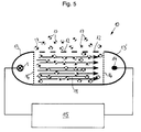
- FIG. 5 shows a device, generally designated 10, for measuring the concentration of a gas, for example, contained in the ambient air.
- the device has a measuring chamber 11 with a gas-permeable outer wall 12 through which the gas atoms shown as balls in FIG. 5 can diffuse from the surroundings of the device 10 into the measuring chamber 11.
- the device 1 shown in FIG. 3 is arranged at one end of the measuring chamber 11 and has an absorption layer 4 designed as a black radiator, which is arranged in the beam path of a laser diode 3 operated by a pulsable current source and is periodically heated by the latter.
- the absorption layer 4 thus emits periodic, recurring broadband radiation pulses in accordance with Plank's law of radiation at time intervals predetermined by the pulse cycle.
- the absorption layer 4 is followed by a narrow-band filter 9 (FIG. 3), the transmission window of which is matched to an absorption wavelength of the gas to be measured.
- the device 1 is arranged in the focal point of a parabolic mirror 13 (FIG. 5), which is that of the device 1 emits radiation so that it penetrates the measuring chamber 11 and reaches a receiver 14 arranged on the end of the measuring chamber 11 facing away from the device 1.
- the receiver 14 is also arranged in the focal point of a parabolic mirror 13 '.
- the device 1 and the receiver 14 are connected to an evaluation and control device 15, which evaluates the signal detected by the receiver 14 synchronously with the transmission pulses of the device 1, in each case at the time of the greatest radiation intensity.
- the radiation passing through the measuring chamber is weakened to a greater or lesser extent by absorption.
- the measurement signal detected by the receiver 14 thus represents a measure of the gas concentration in the measurement chamber 11, so that this can be determined in the evaluation and control device after the measurement values have been processed.
- the device 10 has only a very low average power consumption because of the laser diode 3 operated in pulse mode and is therefore particularly well suited for battery or rechargeable battery operation.
- the device 10 can be used, for example, as a fire detector if the wavelength of the narrowband filter 9 is matched to the absorption wavelength of CO2 (4.7 ⁇ ) and / or CO (4.3 ⁇ ). In the case of battery or rechargeable battery operation, such a fire detector works independently of the mains, so that the fire detector remains fully functional even in the event of a power failure or in the event of faults in the electrical power supply.
- the receiver 14 and the device 1 for the parabolic mirrors 13, 13 ' are provided with a radiation-permeable cover 16.
- the device 10 can then also be used, for example, for detecting aggressive gas.
Abstract
Description
Die Erfindung bezieht sich auf eine Vorrichtung zum Erzeugen einer Breitbandstrahlung mit wenigstens einem, mit einer Energiequelle beheizbaren Breitbandstrahler zum Abstrahlen eines elektromagnetischen Breitband-Spektrums, insbesondere einem Schwarz- oder Graustrahler.The invention relates to a device for generating broadband radiation with at least one broadband radiator that can be heated with an energy source for radiating an electromagnetic broadband spectrum, in particular a black or gray radiator.
Aus DE-41 26 361 A1 kennt man bereits einen Breitbandstrahler der eingangs genannten Art, der als Glühlampe mit einer von anorganischem Material umschlossenen Glühwendel ausgebildet ist. Solche Breitbandstrahler finden beispielsweise in Gasanalysegeräten Verwendung, um mittels photometrischer Verfahren die Konzentration bestimmter Gase zu messen. Dabei ist dem Breitbandstrahler vorzugsweise ein Schmalband-Filter nachgeschaltet, dessen Durchlaßbereich auf eine Absorptionswellenlänge des zu messenden Gases abgestimmt ist. Die so gefilterte Strahlung durchläuft dann eine Meßkammer, in der sich das zu messende Gas befindet. Abhängig von der Konzentration des Gases wird die Strahlung in der Meßkammer mehr oder weniger stark absorbiert, was mittels eines der Meßkammer nachgeschalteten Strahlungsintensitätssensor detektiert und zum Ermitteln der Strahlungsintensität ausgewertet wird. Vorteilhaft ist bei dem vorbekannten Breitbandstrahlers, daß aufgrund der breitbandigen Abstrahlcharakteristik des Strahlers durch Kombination mit einem geeigneten Schmalband-Filter eine Schmalbandstrahlung praktisch beliebiger Wellenlänge erzeugt werden kann, so daß ein mit dem Breitbandstrahler bestücktes Gasmeßgerät auf einfache Weise an die Absorptionswellenlängen unterschiedlicher Gase angepaßt werden kann. Ein Nachteil des vorbekannten Breitbandstrahlers besteht jedoch darin, daß die Glühwendel einen nicht unerheblichen Stromverbrauch aufweist, was besonders bei batteriebetriebenen Gasmeßgeräten, wie sie beispielsweise in Brandmeldern zur Detektion von CO oder CO2 Verwendung finden, ungünstig ist. In größeren Gebäuden, beispielsweise in Fabrikhallen, Kaufhäusern oder Bürogebäuden sind oft einige Hundert solcher Brandmelder installiert, die bei einem Stromausfall aus Sicherheitsgründen noch mehrere Tage lang funktionsbereit sein müssen. Für ein Brandmeldesystem ergibt sich daher bereits bei einer Leistungsaufnahme von nur wenigen Watt für jeden der in den Brandmeldern enthaltenen Breitbandstrahlern eine beachtliche Gesamtleistung, die eine entsprechend aufwendige und teuere Notstromversorgung erfordert.From DE-41 26 361 A1 one already knows a broadband radiator of the type mentioned at the outset, which is designed as an incandescent lamp with an incandescent filament enclosed by inorganic material. Such broadband emitters are used, for example, in gas analyzers to measure the concentration of certain gases by means of photometric methods. The broadband radiator is preferably followed by a narrowband filter, the pass band of which is matched to an absorption wavelength of the gas to be measured. The radiation filtered in this way then passes through a measuring chamber in which the gas to be measured is located. Depending on the concentration of the gas, the radiation is more or less strongly absorbed in the measuring chamber, which is detected by means of a radiation intensity sensor connected downstream of the measuring chamber and is evaluated to determine the radiation intensity. It is advantageous in the known broadband radiator that due to broadband radiation characteristic of the radiator can be generated by combination with a suitable narrowband filter, a narrowband radiation of practically any wavelength, so that a gas meter equipped with the broadband radiator can be easily adapted to the absorption wavelengths of different gases. A disadvantage of the known broadband radiator, however, is that the incandescent filament has a not inconsiderable power consumption, which is particularly unfavorable in battery-operated gas measuring devices, such as those used in fire detectors for detecting CO or CO2. In larger buildings, for example in factory halls, department stores or office buildings, several hundred such fire detectors are often installed, which must remain operational for several days in the event of a power failure for safety reasons. For a fire detection system, therefore, with a power consumption of just a few watts, each of the broadband emitters contained in the fire detectors has a remarkable total output, which requires a correspondingly complex and expensive emergency power supply.
Es besteht deshalb die Aufgabe, eine Vorrichtung der eingangs genannten Art zu schaffen, bei welcher der Energieverbrauch bzw. die Leistungsaufnahme reduziert ist und die insbesondere auch für Batterie- oder Akkubetrieb geeignet ist.The object is therefore to create a device of the type mentioned at the outset in which the energy consumption or the power consumption is reduced and which is also particularly suitable for battery or accumulator operation.
Die Lösung dieser Aufgabe besteht bei einer Vorrichtung der eingangs genannten Art darin, daß der Breitbandstrahler als dünne Schicht mit niedriger Wärmekapazität ausgebildet ist und daß zum Beheizen des Breitbandstrahlers eine pulsbare Energiequelle mit geringer mittlerer Leistung vorgesehen ist, deren Ausgangspulse bezüglich ihrer Pulsenergie und ihres Puls-Pausen-Verhältnisses so auf die Wärmekapazität des Breitbandstrahlers abgestimmt sind, daß dieser in den Pulspausen weitgehend abkühlt.The solution to this problem in a device of the type mentioned is that the broadband radiator is designed as a thin layer with low heat capacity and that a pulsable energy source with low average power is provided for heating the broadband radiator, the output pulses with respect to their pulse energy and their pulse The pause ratio is so matched to the heat capacity of the broadband radiator that it largely cools down in the pulse pauses.
Der Breitbandstrahler ist also als dünne Schicht ausgebildet und weist daher trotz seiner niedrigen Wärmekapazität eine vergleichsweise große Abstrahlfläche auf. Der Breitbandstrahler kann dadurch innerhalb kurzer Zeit, beispielsweise in einer Millisekunde, von Raumtemperatur auf die vorgesehene Betriebstemperatur erwärmt werden. Zum Beheizen ist der Breitbandstrahler mit einer pulsbaren Energiequelle gekoppelt, deren Pulsenergie so auf die Wärmekapazität des Breitbandstrahlers abgestimmt ist, daß dieser während der Pulszeit auf Betriebstemperatur aufgeheizt wird und in den Pulspausen weitgehend abkühlt. Wegen der niedrigen Wärmekapazität des Breitbandstrahlers ist zu dessen Erwärmen auf Betriebstemperatur nur eine vergleichsweise kleine Energiemenge bzw. eine entsprechend geringe Heizleistung erforderlich. Da die Vorrichtung während der Pulspausen praktisch keine Energie aufnimmt und auch während der Pulsphasen nur eine geringe Energiemenge benötigt wird, weist die Vorrichtung insgesamt einen niedrigen mittleren Energieverbrauch auf, was besonders bei einer Verwendung der Vorrichtung in batteriebetriebenen Geräten vorteilhaft ist. Da es für viele Anwendungsfälle, insbesondere bei Überwachungsaufgaben ausreichend ist, Messungen in bestimmten Zeitabständen durchzuführen, ohne daß dadurch Informationsverluste auftreten, wirkt sich die getaktete Betriebsweise des Breitbandstrahlers in der Praxis praktisch nicht nachteilig aus. Die geringe Wärmekapazität des Breitbandstrahlers ermöglicht ein Aussenden optischer Strahlungsimpulse in schneller Folge, so daß die erfindungsgemäße Vorrichtung bei den meisten Anwendungen, beispielsweise in der industriellen Gasanalyse, in Brandmeldern oder in der Umweltmeßtechnik trotz der getakteten Betriebsweise für quasi-kontinuierliche Messungen eingesetzt werden kann.The broadband radiator is thus designed as a thin layer therefore has a comparatively large radiation area despite its low heat capacity. As a result, the broadband radiator can be heated from room temperature to the intended operating temperature in a short time, for example in one millisecond. For heating, the broadband radiator is coupled to a pulsable energy source, the pulse energy of which is so matched to the thermal capacity of the broadband radiator that it is heated to operating temperature during the pulse time and largely cools down in the pulse pauses. Because of the low thermal capacity of the broadband radiator, only a comparatively small amount of energy or a correspondingly low heating output is required to heat it to operating temperature. Since the device absorbs practically no energy during the pulse pauses and only a small amount of energy is required even during the pulse phases, the device overall has a low average energy consumption, which is particularly advantageous when the device is used in battery-operated devices. Since it is sufficient for many applications, in particular for monitoring tasks, to carry out measurements at certain time intervals without loss of information, the clocked mode of operation of the broadband radiator has practically no disadvantage in practice. The low heat capacity of the broadband radiator enables optical radiation pulses to be emitted in rapid succession, so that the device according to the invention can be used for quasi-continuous measurements in most applications, for example in industrial gas analysis, in fire detectors or in environmental measurement technology, despite the clocked mode of operation.
Bei einer Weiterbildung der Erfindung ist als Energiequelle zum Beheizen des Breitbandstrahlers eine optische Halbleiterstrahlungsquelle, insbesondere eine Laserdiode vorgesehen, wobei der Breitbandstrahler im wesentlichen aus einer Absorptionsschicht besteht oder eine solche aufweist, die im Strahlengang der Halbleiterstrahlungsquelle angeordnet ist. Die praktisch trägheitslos arbeitende Halbleiterstrahlungsquelle ermöglicht ein besonders schnelles und verlustarmes Erwärmen der Absorptionsschicht. Vorteilhaft ist dabei insbesondere, daß Halbleiterstrahlungsquellen, beispielsweise Laser- oder Leuchtdioden als Serienbauelemente in großen Stückzahlen kostengünstig verfügbar sind. Besonders geeignet als Energiequelle sind Laserdioden, da sie wegen ihrer hohen Pulsenergien, der kurzen Pulszeiten und des kleinen Abstrahlwinkels besonders hohe Energiedichten und damit entsprechend kurze Aufheizzeiten für die Absorptionsschicht ermöglichen.In a further development of the invention, an optical semiconductor radiation source, in particular a laser diode, is provided as the energy source for heating the broadband radiator, the broadband radiator essentially consisting of or having an absorption layer which is arranged in the beam path of the semiconductor radiation source. The practical Inertia-free semiconductor radiation source enables the absorption layer to be heated particularly quickly and with little loss. It is particularly advantageous that semiconductor radiation sources, for example laser or light-emitting diodes, are inexpensively available in large quantities as series components. Laser diodes are particularly suitable as energy sources because their high pulse energies, short pulse times and small beam angle enable particularly high energy densities and thus correspondingly short heating times for the absorption layer.
Zweckmäßigerweise ist vorgesehen, daß zum Einstellen der Strahlungstemperatur der Absorptionsschicht die Pulsdauer und/oder die Intensität der Halbleiterstrahlung veränderbar ist. Die Strahlungsintensität der Absorptionsschicht kann dadurch auf einfache Weise an die jeweilige Anwendung, beispielsweise an eine in einem Meßsystem vorhandene Übertragungsstrecke angepaßt werden.It is expediently provided that the pulse duration and / or the intensity of the semiconductor radiation can be changed in order to adjust the radiation temperature of the absorption layer. The radiation intensity of the absorption layer can thereby be adapted in a simple manner to the respective application, for example to a transmission link present in a measuring system.
Eine Ausführungsform sieht vor, daß das Material oder die Materialzusammensetzung der Absorptionsschicht an ein für die Breitbandstrahlung vorgegebenes Abstrahlspektrum, insbesondere an ein von dem Spektrum eines schwarzen oder grauen Strahlers abweichendes Spektrum, angepaßt ist. Der Spektralbereich der Vorrichtung kann dadurch beispielsweise auf die Filtercharakteristik eines nachgeschalteten optischen Filters abgestimmt werden. Dabei kann als Absorptionsschicht beispielsweise eine Platin-, Titan-, Aluminiumoxyd oder eine Sinterkeramik-Schicht vorgesehen sein.One embodiment provides that the material or the material composition of the absorption layer is adapted to a radiation spectrum specified for broadband radiation, in particular to a spectrum which deviates from the spectrum of a black or gray radiator. The spectral range of the device can thus be matched, for example, to the filter characteristic of a downstream optical filter. For example, a platinum, titanium, aluminum oxide or a sintered ceramic layer can be provided as the absorption layer.
Vorteilhaft ist, wenn wenigstens eine für das Spektrum der Breitbandstrahlung relevante Schichteigenschaft der Absorptionsschicht, insbesondere deren Emissionskoeffizient durch elektrische, optische und/oder chemische Beeinflussung der Absorptionsschicht, vorzugsweise während des Betriebs des Breitbandstrahlers, veränderbar ist. Die Vorrichtung kann dadurch besonders gut auf den Spektralbereich von optischen Filtern mit unterschiedlichen Frequenzbereichen abgestimmt werden. Außerdem ist eine Anpassung an die spektrale Empfindlichkeit von mit dem Breitbandstrahler gekoppelten Empfängern möglich.It is advantageous if at least one layer property of the absorption layer that is relevant for the spectrum of the broadband radiation, in particular its emission coefficient, can be changed by electrical, optical and / or chemical influencing of the absorption layer, preferably during operation of the broadband radiator. The device can thereby be particularly good the spectral range of optical filters with different frequency ranges can be tuned. It is also possible to adapt to the spectral sensitivity of receivers coupled to the broadband radiator.
Eine Weiterbildung der Erfindung sieht vor, daß die Absorptionsschicht oder der Breitbandstrahler auf einem vorzugsweise für die Halbleiterstrahlung strahlungsdurchlässigen Träger, insbesondere einer Trägerplatte mit hohem Wärmeleitungswiderstand angeordnet ist. Die Absorptionsschicht kann dadurch besonders dünn, beispielsweise als auf eine Quarzglasplatte aufgedampfte Schicht ausgebildet sein, und weist dennoch in Kombination mit dem Träger eine gute mechanische Stabilität auf.A further development of the invention provides that the absorption layer or the broadband radiator is arranged on a carrier which is preferably transparent to the semiconductor radiation, in particular a carrier plate with high thermal conductivity. As a result, the absorption layer can be particularly thin, for example in the form of a layer evaporated onto a quartz glass plate, and nevertheless has good mechanical stability in combination with the carrier.
Eine besonders vorteilhafte Ausführungsform sieht vor, daß der Halbleiterstrahler als optoelektronisches Bauelement in ein Gehäuse integriert ist, daß die Absorptionsschicht integrales Bestandteil dieses Gehäuses ist und vorzugsweise mikromechanisch an das Gehäuse angebunden ist. Die Vorrichtung weist dann einen besonders kompakten Aufbau auf und kann als optoelektronisches Standardbauelement auf einfache Weise in eine elektronische Schaltung integriert werden.A particularly advantageous embodiment provides that the semiconductor radiator is integrated as an optoelectronic component in a housing, that the absorption layer is an integral part of this housing and is preferably micromechanically connected to the housing. The device then has a particularly compact structure and can be easily integrated into an electronic circuit as an optoelectronic standard component.
Zweckmäßigerweise ist vorgesehen, daß die Halbleiterstrahlungsquelle, die Absorptionsschicht und gegebenenfalls zumindest ein frequenzselektiver optischer Filter für die Breitbandstrahlung eine kompakte Baueinheit bilden. Der optische Filter kann dann für die wichtigsten Absorptionswellenlängen, zum Beispiel für CO2 (4,7 µm), für CO (4,3 µm) oder für jede beliebige andere Wellenlänge gleich in die Baueinheit, beispielsweise in ein Laser- oder Leuchtdiodengehäuse integriert werden, so daß für die einzelnen Wellenlängen Standardbausteine zur Verfügung stehen, mit denen beispielsweise sehr kompakte und einfach aufgebaute Gasmeßgeräte für unterschiedliche Gase realisiert werden können.It is expediently provided that the semiconductor radiation source, the absorption layer and, if appropriate, at least one frequency-selective optical filter for the broadband radiation form a compact structural unit. The optical filter can then be integrated into the structural unit, for example in a laser or light-emitting diode housing, for the most important absorption wavelengths, for example for CO2 (4.7 µm), for CO (4.3 µm) or for any other wavelength, so that standard components are available for the individual wavelengths, with which, for example, very compact and simply constructed gas measuring devices for different gases can be realized.
Vorteilhaft ist, wenn der Halbleiterstrahler in ein Gehäuse integriert ist, das zumindest in einem Teilbereich für die Halbleiterstrahlung strahlungsdurchlässig ist und daß die Absorptionsschicht in diesem Teilbereich des Gehäuses an der Gehäuseaußenwandung vorgesehen ist. Die Vorrichtung kann dadurch besonders kostengünstig durch Aufdampfen oder dergleichen Aufbringen einer Absorptionsschicht auf das Gehäuse eines handelsüblichen Halbleiterstrahlers, beispielsweise einer Laser- oder Leuchtdiode, hergestellt werden.It is advantageous if the semiconductor radiator is integrated in a housing which is radiation-permeable to the semiconductor radiation at least in a partial region and that the absorption layer is provided on the outer wall of the housing in this partial region of the housing. As a result, the device can be produced particularly cost-effectively by vapor deposition or the like application of an absorption layer to the housing of a commercially available semiconductor emitter, for example a laser or light-emitting diode.
Bei einer anderen Ausführungsform ist der Halbleiterstrahler so in ein Gehäuse integriert, daß die Absorptionsschicht in einem von der Halbleiterstrahlung beaufschlagten Bereich der Innenwandung dieses Gehäuses vorgesehen ist und daß wenigstens ein Teilbereich des Gehäuses zumindest in einem bestimmten Wellenlängenbereich der Breitbandstrahlung strahlungsdurchlässig ist. Die Absorptionsschicht ist also in diesem Fall an der Innenwandung des Gehäuses vorgesehen und ist dadurch besonders gut gegen mechanische Beschädigung oder gegen Abrieb geschützt.In another embodiment, the semiconductor radiator is integrated into a housing in such a way that the absorption layer is provided in a region of the inner wall of this housing that is exposed to the semiconductor radiation and that at least a partial region of the housing is transparent to radiation at least in a certain wavelength range of the broadband radiation. In this case, the absorption layer is therefore provided on the inner wall of the housing and is therefore particularly well protected against mechanical damage or against abrasion.
Bedarfsweise kann das Gehäuse zumindest in seinem strahlungsdurchlässigen Teilbereich als frequenzselektriver optischer Filter, insbesondere als Interferenzfilter ausgebildet sein. Die Abstrahlcharakteristik der Vorrichtung kann dadurch praktisch beliebig beeinflußt werden, wobei insbesondere durch Ausbildung des strahlungsdurchlässigen Gehäuse-Teilbereichs als Interferenzfilter sehr schmalbandige Strahler mit nahezu beliebiger Wellenlänge realisiert werden können. Als Interferenzfilter kann beispielsweise eine dünne Metall- bzw. Goldschicht auf die Außenseite des Gehäuses aufgedampft sein.If necessary, the housing can be designed as a frequency-selective optical filter, in particular as an interference filter, at least in its radiation-permeable partial area. The radiation characteristic of the device can thereby be influenced practically as desired, in particular by designing the radiation-permeable housing sub-region as an interference filter, very narrow-band radiators with almost any wavelength can be realized. A thin metal or gold layer can, for example, be evaporated onto the outside of the housing as an interference filter.
Eine Ausführungsform der Erfindung sieht vor, daß der Breitbandstrahler im wesentlichen aus einer elektrisch leitfähigen Widerstandsschicht besteht und daß als Energiequelle zum Beheizen des Strahlers eine Pulsstromquelle vorgesehen ist. Die Vorrichtung ist dann besonders einfach und kostengünstig herstellbar.One embodiment of the invention provides that the broadband radiator essentially consists of an electrically conductive resistance layer and that a pulse current source is provided as the energy source for heating the radiator. The device is then particularly simple and inexpensive to manufacture.
Eine Weiterbildung der Erfindung sieht vor, daß der Breitbandstrahler zum Messen der Konzentration zumindest eines Gases mit wenigstens einem Empfänger elektromagnetisch gekoppelt ist, daß in einem zwischen dem Breitbandstrahler und der Empfänger befindlichen Strahlengang sich das zu detektierende Gas befindet und daß in dem Strahlengang zumindest ein frequenzselektiver optischer Filter angeordnet ist, dessen Durchlaßbereich auf wenigstens eine Absorptionswellenlänge des zu messenden Gases abgestimmt ist. Eine solche Vorrichtung kann beispielsweise als Brandmelder ausgebildet sein, wenn als Filter ein Schmalband-Filter mit einem Durchlaßfenster im Bereich der Absorptionswellenlängen von CO2 (4,7 µm) und/oder CO (4,3 µm) vorgesehen ist. Dabei fällt das Empfangssignal mit zunehmender Konzentration der vorgenannten Gase im Strahlengang ab, was beim Unterschreiten eines vorgegebenen Schwellwertes beispielsweise mittels einer geeigneten Steuer- und Auswertevorrichtung in ein Brandwarnsignal umgesetzt werden kann. Wegen des geringen Stromverbrauchs eignet sich eine solche Vorrichtung besonders für batteriebetriebene oder akkugepufferte Geräte.A further development of the invention provides that the broadband radiator for measuring the concentration of at least one gas is electromagnetically coupled to at least one receiver, that the gas to be detected is located in a beam path between the broadband radiator and the receiver, and that at least one frequency-selective one is in the beam path Optical filter is arranged, the pass band is matched to at least one absorption wavelength of the gas to be measured. Such a device can be designed, for example, as a fire detector if a narrow-band filter with a pass-through window in the range of the absorption wavelengths of CO2 (4.7 μm) and / or CO (4.3 μm) is provided as the filter. In this case, the received signal drops with increasing concentration of the aforementioned gases in the beam path, which can be converted into a fire warning signal, for example by means of a suitable control and evaluation device, if a predetermined threshold value is undershot. Because of the low power consumption, such a device is particularly suitable for battery-operated or battery-backed devices.
Nachfolgend sind Ausführungsbeispiele der Erfindung anhand der Zeichnung näher erläutert.Exemplary embodiments of the invention are explained in more detail below with reference to the drawing.
Es zeigen in unterschiedlichen Maßstäben und zum Teil stärker schematisiert:
- Fig.1
- einenen Längsschnitt durch eine Vorrichtung zum Erzeugen einer breitbandigen optischen Strahlung, mit einer Halbleiterlichtquelle, in deren Strahlengang eine auf eine Trägerplatte aufgebrachte dünne Absorptionsschicht angeordnet ist,
- Fig.2
- eine Aufsicht auf die in Fig.1 gezeigte Vorrichtung, welche die Absorptionsschicht besonders gut erkennen läßt,
- Fig.3
- einen Längsschnitt einer Vorrichtung ähnlich Fig.1, wobei jedoch die Absorptionsschicht innenseitig an der Trägerplatte vorgesehen ist und an der Außenseite der Trägerplatte ein Filter für die von der Absorptionsschicht emitierte Breitbandstrahlung angeordnet ist,
- Fig.4
- eine Ansicht auf die Ebene A-A in Figur 3, wobei die mikromechanische Anbindung der Absorptionsschicht an das Vorrichtungsgehäuse besonders gut erkennbar ist und
- Fig.5
- eine Vorrichtung zum Messen der Konzentration eines in einer Meßkammer befindlichen Gases, wobei an dem einen Ende der Meßkammer die in Fig.3 gezeigte Breitbandstrahlungs-Vorrichtung und an dem anderen Ende ein optischer Empfänger angeordnet ist, die jeweils mit einer Auswerte- und Steuereinheit verbunden sind.
- Fig. 1
- 1 shows a longitudinal section through a device for generating broadband optical radiation, with a semiconductor light source, in the beam path of which a thin absorption layer applied to a carrier plate is arranged,
- Fig. 2
- 2 shows a top view of the device shown in FIG. 1, which shows the absorption layer particularly well,
- Fig. 3
- 2 shows a longitudinal section of a device similar to FIG. 1, however the absorption layer is provided on the inside of the carrier plate and a filter for the broadband radiation emitted by the absorption layer is arranged on the outside of the carrier plate,
- Fig. 4
- a view of the plane AA in Figure 3, wherein the micromechanical connection of the absorption layer to the device housing is particularly well recognizable and
- Fig. 5
- a device for measuring the concentration of a gas in a measuring chamber, the broadband radiation device shown in FIG. 3 being arranged at one end of the measuring chamber and an optical receiver at the other end, each of which is connected to an evaluation and control unit .
Eine im ganzen mit 1 bezeichnete Vorrichtung zum Erzeugen einer Breitbandstrahlung weist eine in ein Vorrichtungsgehäuse 2 integrierte Laserdiode 3 auf, in deren Strahlengang eine die Laserstrahlung absorbierende Absorptionsschicht 4 angeordnet ist. Die Absorptionsschicht 4 ist an der äußeren Flachseite einer mit dem Vorrichtungsgehäuse 2 verbundenen Trägerplatte 5 aus Quarzglas angeordnet, die für die Laserstrahlung der Laserdiode 3 durchlässig ist. Die Absorptionsschicht 4 ist sehr dünn ausgebildet und weist bei einer vergleichsweise großen Fläche nur eine geringe Wärmekapazität auf. Durch Bestrahlung mit der Laserstrahlung der Laserdiode 3 kann die Absorptionsschicht 4 innerhalb von etwa einer Millisekunde von Raumtemperatur auf mehrere 100° C erhitzt werden. Die so erhitzte Absorptionsschicht strahlt dann nach dem Plank'schen Strahlungsgesetz als Schwarz- oder Graustrahler eine breitbandige elektromagnetische Strahlung ab. Als Stromquelle für die Laserdiode 3 weist die Vorrichtung 1 ferner eine pulsbare Energiequelle 6 auf, deren Puls-Pausen-Verhältnis so auf die Wärmekapazität der Absorptionsschicht 4 abgestimmt ist, daß diese in der Pulsphase auf Betriebstemperatur erhitzt wird und in den Pulspausen weitgehend abkühlt. Da die Laserdiode 3 während der Pulspausen keinen Betriebsstrom benötigt, weist die Vorrichtung bei einem entsprechenden Puls-Pausen-Verhältnis einen sehr niedrigen Energieverbrauch auf. Wenn die Vorrichtung beispielsweise in einem Meßsystem eingesetzt wird, mit dem pro Sekunde etwa eine Messung durchgeführt werden soll, ergibt sich bei einer Pulszeit von einer Millisekunde etwa ein Puls-Pausen-Verhältnis von 1 : 1000. Die Stromaufnahme der Vorrichtung 1 ist dadurch gegenüber dem cw-Betrieb der Laserdiode 3 etwa um drei Zehnerpotenzen reduziert. Die Vorrichtung ist deshalb besonders für Batterie- oder Akku-Betrieb geeignet.A device designated as 1 for generating broadband radiation has a laser diode 3 integrated in a
Zum Einstellen der Strahlungstemperatur der Absorptionsschicht 4 bzw. der Intensität der abgestrahlten elektromagnetischen Strahlung ist die Pulsdauer t der Energiequelle 6 einstellbar (Fig.1). Bei der in Fig.3 gezeigten Ausführungsform ist zum Einstellen der Strahlungstemperatur der Absorptionsschicht 4 die Intensität der Laserstrahlung der Laserdiode 3 durch Einstellen des Pulsstromes I der Energiequelle 6 veränderbar.The pulse duration t of the energy source 6 can be adjusted to set the radiation temperature of the
Bei dem Ausführungsbeispiel nach Fig. 1 ist die Absorptionsschicht 4 außenseitig auf die Trägerplatte 5 aufgebracht. Die Trägerplatte 5 weist eine geringe Wärmeleitungsfähigkeit auf, damit die Absorptionsschicht 4 mit der von der Laserdiode 3 emittierten Laserstrahlung möglichst schnell auf die gewünschte Abstrahltemperatur erhitzt werden kann. Die Trägerplatte 5 weist außerdem im Bereich der Wellenlänge der Laserdiodenstrahlung eine hohe Transparenz auf, damit die Laserdiodenstrahlung möglichst verlustfrei zu der Absorptionsschicht 4 gelangen kann.In the exemplary embodiment according to FIG. 1, the
Bei der in Fig.3 gezeigten Ausführungsform ist die Absorptionsschicht 4 dicht benachbart zur Innenseite 7 der Trägerplatte 5 in dem Vorrichtungsgehäuse 2 angeordnet. Die Befestigung der Absorptionsschicht 4 erfolgt hier mittels mikromechanischer Anbindung 8 seitlich an dem Vorrichtungsgehäuse 2. Die Absorptionsschicht 4 ist dadurch praktisch frei in dem Vorrichtungsgehäuse 2 aufgehängt, so daß die Wärmeleitungsverluste der Absorptionsschicht 4 entsprechend gering sind.
Bei der Vorrichtung nach Fig. 3 ist außenseitig auf die Trägerplatte 5 ein Schmalband-Filter 9 aufgebracht. Durch Kombination mit unterschiedlichen Filtern 9 kann mit der Vorrichtung 1 praktisch in beliebigen Wellenlängenbereichen eine schmalbandige elektromagnetische Strahlung erzeugt werden. Die Abstrahlwellenlänge der Vorrichtung 1 kann dadurch auf einfache Weise an die Absorptionswellenlängen unterschiedlicher Gase angepaßt werden, weshalb die Vorrichtung 1 besonders gut für eine Verwendung in Gasmeßgeräten geeignet ist.In the embodiment shown in Figure 3, the
3, a narrow-band filter 9 is applied to the outside of the
Fig.5 zeigt eine im ganzen mit 10 bezeichnete Vorrichtung zur Messung der Konzentration eines beispielsweise in der Umgebungsluft enthaltenen Gases. Die Vorrichtung weist eine Meßkammer 11 mit einer gasdurchlässigen Außenwandung 12 auf, durch welche die in Fig.5 als Kugeln dargestellten Gasatome aus der Umgebung der Vorrichtung 10 in die Meßkammer 11 diffundieren können. An einem stirnseitigen Ende der Maßkammer 11 ist die in Fig. 3 gezeigte Vorrichtung 1 angeordnet, die eine als Schwarzstrahler ausgebildete Absorptionsschicht 4 aufweist, die im Strahlengang einer von einer pulsbaren Stromquelle betriebenen Laserdiode 3 angeordnet ist und von dieser periodisch erhitzt wird. Die Absorptionsschicht 4 strahlt dadurch nach dem Plank'schen Strahlungsgesetz in durch den Pulstakt vorgegebenen Zeitabständen periodische wiederkehrende breitbandige Strahlungsimpulse aus. Der Absorptionsschicht 4 ist ein Schmalband-Filter 9 (Fig.3) nachgeschaltet, dessen Durchlaßfenster auf eine Absorptionswellenlänge des zu messenden Gases abgestimmt ist. Die Vorrichtung 1 ist im Brennpunkt eines Parabolspiegels 13 angeordnet (Fig. 5), der die von der Vorrichtung 1 ausgesendete Strahlung so bündelt, daß diese die Meßkammer 11 durchdringt und zu einem an dem der Vorrichtung 1 abgewandten stirnseitigen Ende der Meßkammer 11 angeordneten Empfänger 14 gelangt. Um die Empfindlichkeit der Vorrichtung 10 zu verbessern, ist der Empfänger 14 ebenfalls im Brennpunkt eines Parabolspiegels 13' angeordnet. Die Vorrichtung 1 und der Empfänger 14 sind mit einer Auswerte- und Steuereinrichtung 15 verbunden, die synchron zu den Sendeimpulsen der Vorrichtung 1, jeweils zum Zeitpunkt der größten Strahlungsintensität das von dem Empfänger 14 detektierte Signal auswertet. Abhängig von der Konzentration des zu messenden Gases in der Meßkammer 11 wird die die Meßkammer durchlaufende Strahlung durch Absorption mehr oder weniger stark geschwächt. Das von dem Empfänger 14 detektierte Meßsignal stellt somit ein Maß für die Gaskonzentration in der Meßkammer 11 dar, so daß diese nach Aufbereitung der Meßwerte in der Auswerte- und Steuereinrichtung ermittelt werden kann.
Besonders vorteilhaft ist, daß die Vorrichtung 10 wegen der im Pulsbetrieb betriebenen Laserdiode 3 nur eine sehr geringe mittlere Leistungsaufnahme aufweist und daher besonders gut für Batterie- odr Akku-Betrieb geeignet ist. Die Vorrichtung 10 kann beispielsweise als Brandmelder verwendet werden, wenn die Wellenlänge des Schmalband-Filters 9 auf die Absorptionswellenlänge von CO2 (4,7µ) und/oder CO (4,3µ) abgestimmt ist. Bei Batterie- oder Akku-Betrieb arbeitet ein solcher Brandmelder netzunabhängig, so daß auch bei einem Stromausfall oder bei Störungen in der elektrischen Energieversorgung die volle Funktionsfähigkeit des Brandmelders erhalten bleibt.FIG. 5 shows a device, generally designated 10, for measuring the concentration of a gas, for example, contained in the ambient air. The device has a measuring
It is particularly advantageous that the
Erwähnt werden soll noch, daß bei der in Fig.5 gezeigten Vorrichtung 10 für die Parabolspiegel 13, 13' den Empfänger 14 und die Vorrichtung 1 eine strahlungsdurchlässige Abdeckung 16 vorgesehen ist. Die Vorrichtung 10 kann dann beispielsweise auch zum detektieren aggresiver Gaser verwendet werden.It should also be mentioned that in the
Claims (13)
Applications Claiming Priority (2)
| Application Number | Priority Date | Filing Date | Title |
|---|---|---|---|
| DE19944437311 DE4437311A1 (en) | 1994-10-19 | 1994-10-19 | Device for generating broadband radiation |
| DE4437311 | 1994-10-19 |
Publications (2)
| Publication Number | Publication Date |
|---|---|
| EP0708316A2 true EP0708316A2 (en) | 1996-04-24 |
| EP0708316A3 EP0708316A3 (en) | 1996-12-18 |
Family
ID=6531135
Family Applications (1)
| Application Number | Title | Priority Date | Filing Date |
|---|---|---|---|
| EP95116153A Withdrawn EP0708316A3 (en) | 1994-10-19 | 1995-10-13 | Device for generating broadband radiation |
Country Status (2)
| Country | Link |
|---|---|
| EP (1) | EP0708316A3 (en) |
| DE (1) | DE4437311A1 (en) |
Cited By (1)
| Publication number | Priority date | Publication date | Assignee | Title |
|---|---|---|---|---|
| EP1821087A2 (en) | 2006-02-21 | 2007-08-22 | Deutsches Zentrum für Luft- und Raumfahrt e.V. | Temperature emitter |
Families Citing this family (2)
| Publication number | Priority date | Publication date | Assignee | Title |
|---|---|---|---|---|
| DE19922590C2 (en) * | 1999-03-08 | 2001-10-18 | Inst Chemo Biosensorik | Infrared gas sensor and method for operating the infrared gas sensor |
| JP4663883B2 (en) | 1999-03-08 | 2011-04-06 | ガスビートル ゲーエムベーハー | Gas sensor and method of operating gas sensor |
Citations (1)
| Publication number | Priority date | Publication date | Assignee | Title |
|---|---|---|---|---|
| DE4126364A1 (en) | 1991-08-06 | 1992-06-17 | Heinz Prof Dr Gatzmanga | Thermal radiation source for IR range - has enamel body with embedded resistive radiation wire for energising IR radiation from body |
Family Cites Families (5)
| Publication number | Priority date | Publication date | Assignee | Title |
|---|---|---|---|---|
| DE1936245A1 (en) * | 1969-07-16 | 1971-02-04 | Beckman Instruments Gmbh | Infrared heater arrangement |
| NO170366C (en) * | 1989-05-26 | 1997-02-10 | Kanstad Teknologi As | Pulsed infrared radiation source |
| DE4140988C2 (en) * | 1991-12-12 | 1996-04-25 | Max Planck Gesellschaft | Generation of Planck's blackbody radiation with a point light source |
| DE4216085A1 (en) * | 1992-05-15 | 1992-12-10 | Merkel Wolfgang | IR gas analyser for continuously measuring multiple atom, non-elementary gas - uses alternating IR beam, absorption cuvette, interference filter, radiation receiver and evaluation circuit |
| US5408101A (en) * | 1992-07-06 | 1995-04-18 | Telaire Systems, Inc. | Laser assisted quasi-blackbody radiation source |
-
1994
- 1994-10-19 DE DE19944437311 patent/DE4437311A1/en not_active Withdrawn
-
1995
- 1995-10-13 EP EP95116153A patent/EP0708316A3/en not_active Withdrawn
Patent Citations (1)
| Publication number | Priority date | Publication date | Assignee | Title |
|---|---|---|---|---|
| DE4126364A1 (en) | 1991-08-06 | 1992-06-17 | Heinz Prof Dr Gatzmanga | Thermal radiation source for IR range - has enamel body with embedded resistive radiation wire for energising IR radiation from body |
Cited By (4)
| Publication number | Priority date | Publication date | Assignee | Title |
|---|---|---|---|---|
| EP1821087A2 (en) | 2006-02-21 | 2007-08-22 | Deutsches Zentrum für Luft- und Raumfahrt e.V. | Temperature emitter |
| EP1821087A3 (en) * | 2006-02-21 | 2008-06-18 | Deutsches Zentrum für Luft- und Raumfahrt e.V. | Temperature emitter |
| US8153998B2 (en) | 2006-02-21 | 2012-04-10 | Deutsches Zentrum für Luft- und Raumfahrt e.V. | Temperature radiator |
| DE102006008409B4 (en) * | 2006-02-21 | 2016-12-01 | Deutsches Zentrum für Luft- und Raumfahrt e.V. | Thermal radiators |
Also Published As
| Publication number | Publication date |
|---|---|
| DE4437311A1 (en) | 1996-04-25 |
| EP0708316A3 (en) | 1996-12-18 |
Similar Documents
| Publication | Publication Date | Title |
|---|---|---|
| EP1183520B1 (en) | Gas sensor configuration | |
| EP0874233B1 (en) | Selective gas sensor | |
| DE602004000374T2 (en) | GAS DETECTION METHOD AND GAS DETECTOR EQUIPMENT | |
| EP0855592B1 (en) | Optoacoustic gas sensor | |
| DE69820308T2 (en) | Microtechnological dissipative optical-thermal gas sensor | |
| EP0472668B1 (en) | Process for determining the condition of a road surface | |
| DE102011119431C5 (en) | Stray radiation fire detector and method for automatically detecting a fire situation | |
| DE19608604C2 (en) | Gas analyzer and measuring cell for use in a gas analyzer | |
| EP0704691A2 (en) | Infrared spectrometric gas sensor | |
| DE4433336A1 (en) | Method and device for determining the concentration of a substance, preferably a fluid, particularly preferably a gas | |
| DE19720007C2 (en) | Gas sensor system for the detection of at least one gas or of particles or a combination thereof with two gas sensors, method for its operation and use of the gas sensor system | |
| EP0283047A2 (en) | Method and device for contactless aquisition of data for the spatial resolution of density and temperature in a volume sample | |
| DE2346249C3 (en) | Fire alarm | |
| EP0244721A2 (en) | Method and system for optical transmission measurement | |
| EP0708316A2 (en) | Device for generating broadband radiation | |
| DE4301457A1 (en) | Detector for flammable gases, especially methane | |
| CH665915A5 (en) | DEVICE FOR MONITORING ICE FORMATION. | |
| EP3372988A1 (en) | Method and device for measuring the concentration of a substance in a gaseous medium by means of absorption spectroscopy | |
| DE10221708B4 (en) | Method for determining the concentration of gases and vapors and non-dispersive infrared gas analyzer for carrying out the method | |
| EP0421100B1 (en) | Procedure and equipment for recognizing dangerous conditions in a room | |
| DE10245822B4 (en) | Method and gas measuring cell for the detection of different gases | |
| DE19716061C1 (en) | Infra-red optical gas measuring system e.g. for measurement of alcohol in breath | |
| DE3128777C2 (en) | ||
| DE1797327C2 (en) | Device for measuring the optical reflectivity or the transmittance. Eliminated from: 1622484 | |
| DE19731241C2 (en) | Device and method for determining fluid components and method for producing the device |
Legal Events
| Date | Code | Title | Description |
|---|---|---|---|
| PUAI | Public reference made under article 153(3) epc to a published international application that has entered the european phase |
Free format text: ORIGINAL CODE: 0009012 |
|
| AK | Designated contracting states |
Kind code of ref document: A2 Designated state(s): CH DE DK ES FR GB IT LI NL PT SE |
|
| PUAL | Search report despatched |
Free format text: ORIGINAL CODE: 0009013 |
|
| AK | Designated contracting states |
Kind code of ref document: A3 Designated state(s): CH DE DK ES FR GB IT LI NL PT SE |
|
| RAP1 | Party data changed (applicant data changed or rights of an application transferred) |
Owner name: SOMMER, MICHAEL |
|
| 17P | Request for examination filed |
Effective date: 19970617 |
|
| 17Q | First examination report despatched |
Effective date: 19990727 |
|
| 19U | Interruption of proceedings before grant |
Effective date: 19991113 |
|
| 19W | Proceedings resumed before grant after interruption of proceedings |
Effective date: 20060301 |
|
| STAA | Information on the status of an ep patent application or granted ep patent |
Free format text: STATUS: THE APPLICATION HAS BEEN WITHDRAWN |
|
| 18W | Application withdrawn |
Effective date: 20060301 |