EP0707885A1 - Structured packing with improved capacity for rectification systems - Google Patents
Structured packing with improved capacity for rectification systems Download PDFInfo
- Publication number
- EP0707885A1 EP0707885A1 EP95115585A EP95115585A EP0707885A1 EP 0707885 A1 EP0707885 A1 EP 0707885A1 EP 95115585 A EP95115585 A EP 95115585A EP 95115585 A EP95115585 A EP 95115585A EP 0707885 A1 EP0707885 A1 EP 0707885A1
- Authority
- EP
- European Patent Office
- Prior art keywords
- section
- structured packing
- base region
- packing
- sheets
- Prior art date
- Legal status (The legal status is an assumption and is not a legal conclusion. Google has not performed a legal analysis and makes no representation as to the accuracy of the status listed.)
- Granted
Links
Images




Classifications
-
- B—PERFORMING OPERATIONS; TRANSPORTING
- B01—PHYSICAL OR CHEMICAL PROCESSES OR APPARATUS IN GENERAL
- B01D—SEPARATION
- B01D3/00—Distillation or related exchange processes in which liquids are contacted with gaseous media, e.g. stripping
- B01D3/34—Distillation or related exchange processes in which liquids are contacted with gaseous media, e.g. stripping with one or more auxiliary substances
- B01D3/38—Steam distillation
-
- F—MECHANICAL ENGINEERING; LIGHTING; HEATING; WEAPONS; BLASTING
- F25—REFRIGERATION OR COOLING; COMBINED HEATING AND REFRIGERATION SYSTEMS; HEAT PUMP SYSTEMS; MANUFACTURE OR STORAGE OF ICE; LIQUEFACTION SOLIDIFICATION OF GASES
- F25J—LIQUEFACTION, SOLIDIFICATION OR SEPARATION OF GASES OR GASEOUS OR LIQUEFIED GASEOUS MIXTURES BY PRESSURE AND COLD TREATMENT OR BY BRINGING THEM INTO THE SUPERCRITICAL STATE
- F25J3/00—Processes or apparatus for separating the constituents of gaseous or liquefied gaseous mixtures involving the use of liquefaction or solidification
- F25J3/02—Processes or apparatus for separating the constituents of gaseous or liquefied gaseous mixtures involving the use of liquefaction or solidification by rectification, i.e. by continuous interchange of heat and material between a vapour stream and a liquid stream
- F25J3/04—Processes or apparatus for separating the constituents of gaseous or liquefied gaseous mixtures involving the use of liquefaction or solidification by rectification, i.e. by continuous interchange of heat and material between a vapour stream and a liquid stream for air
- F25J3/04763—Start-up or control of the process; Details of the apparatus used
- F25J3/04866—Construction and layout of air fractionation equipments, e.g. valves, machines
- F25J3/04896—Details of columns, e.g. internals, inlet/outlet devices
- F25J3/04909—Structured packings
-
- B—PERFORMING OPERATIONS; TRANSPORTING
- B01—PHYSICAL OR CHEMICAL PROCESSES OR APPARATUS IN GENERAL
- B01J—CHEMICAL OR PHYSICAL PROCESSES, e.g. CATALYSIS OR COLLOID CHEMISTRY; THEIR RELEVANT APPARATUS
- B01J19/00—Chemical, physical or physico-chemical processes in general; Their relevant apparatus
- B01J19/32—Packing elements in the form of grids or built-up elements for forming a unit or module inside the apparatus for mass or heat transfer
-
- F—MECHANICAL ENGINEERING; LIGHTING; HEATING; WEAPONS; BLASTING
- F25—REFRIGERATION OR COOLING; COMBINED HEATING AND REFRIGERATION SYSTEMS; HEAT PUMP SYSTEMS; MANUFACTURE OR STORAGE OF ICE; LIQUEFACTION SOLIDIFICATION OF GASES
- F25J—LIQUEFACTION, SOLIDIFICATION OR SEPARATION OF GASES OR GASEOUS OR LIQUEFIED GASEOUS MIXTURES BY PRESSURE AND COLD TREATMENT OR BY BRINGING THEM INTO THE SUPERCRITICAL STATE
- F25J3/00—Processes or apparatus for separating the constituents of gaseous or liquefied gaseous mixtures involving the use of liquefaction or solidification
- F25J3/02—Processes or apparatus for separating the constituents of gaseous or liquefied gaseous mixtures involving the use of liquefaction or solidification by rectification, i.e. by continuous interchange of heat and material between a vapour stream and a liquid stream
- F25J3/04—Processes or apparatus for separating the constituents of gaseous or liquefied gaseous mixtures involving the use of liquefaction or solidification by rectification, i.e. by continuous interchange of heat and material between a vapour stream and a liquid stream for air
-
- B—PERFORMING OPERATIONS; TRANSPORTING
- B01—PHYSICAL OR CHEMICAL PROCESSES OR APPARATUS IN GENERAL
- B01J—CHEMICAL OR PHYSICAL PROCESSES, e.g. CATALYSIS OR COLLOID CHEMISTRY; THEIR RELEVANT APPARATUS
- B01J2219/00—Chemical, physical or physico-chemical processes in general; Their relevant apparatus
- B01J2219/32—Details relating to packing elements in the form of grids or built-up elements for forming a unit of module inside the apparatus for mass or heat transfer
- B01J2219/322—Basic shape of the elements
- B01J2219/32203—Sheets
- B01J2219/3221—Corrugated sheets
-
- B—PERFORMING OPERATIONS; TRANSPORTING
- B01—PHYSICAL OR CHEMICAL PROCESSES OR APPARATUS IN GENERAL
- B01J—CHEMICAL OR PHYSICAL PROCESSES, e.g. CATALYSIS OR COLLOID CHEMISTRY; THEIR RELEVANT APPARATUS
- B01J2219/00—Chemical, physical or physico-chemical processes in general; Their relevant apparatus
- B01J2219/32—Details relating to packing elements in the form of grids or built-up elements for forming a unit of module inside the apparatus for mass or heat transfer
- B01J2219/322—Basic shape of the elements
- B01J2219/32203—Sheets
- B01J2219/32213—Plurality of essentially parallel sheets
- B01J2219/3222—Plurality of essentially parallel sheets with sheets having corrugations which intersect at an angle different from 90 degrees
-
- B—PERFORMING OPERATIONS; TRANSPORTING
- B01—PHYSICAL OR CHEMICAL PROCESSES OR APPARATUS IN GENERAL
- B01J—CHEMICAL OR PHYSICAL PROCESSES, e.g. CATALYSIS OR COLLOID CHEMISTRY; THEIR RELEVANT APPARATUS
- B01J2219/00—Chemical, physical or physico-chemical processes in general; Their relevant apparatus
- B01J2219/32—Details relating to packing elements in the form of grids or built-up elements for forming a unit of module inside the apparatus for mass or heat transfer
- B01J2219/322—Basic shape of the elements
- B01J2219/32203—Sheets
- B01J2219/32224—Sheets characterised by the orientation of the sheet
- B01J2219/32227—Vertical orientation
-
- B—PERFORMING OPERATIONS; TRANSPORTING
- B01—PHYSICAL OR CHEMICAL PROCESSES OR APPARATUS IN GENERAL
- B01J—CHEMICAL OR PHYSICAL PROCESSES, e.g. CATALYSIS OR COLLOID CHEMISTRY; THEIR RELEVANT APPARATUS
- B01J2219/00—Chemical, physical or physico-chemical processes in general; Their relevant apparatus
- B01J2219/32—Details relating to packing elements in the form of grids or built-up elements for forming a unit of module inside the apparatus for mass or heat transfer
- B01J2219/322—Basic shape of the elements
- B01J2219/32203—Sheets
- B01J2219/32237—Sheets comprising apertures or perforations
- B01J2219/32241—Louvres
-
- B—PERFORMING OPERATIONS; TRANSPORTING
- B01—PHYSICAL OR CHEMICAL PROCESSES OR APPARATUS IN GENERAL
- B01J—CHEMICAL OR PHYSICAL PROCESSES, e.g. CATALYSIS OR COLLOID CHEMISTRY; THEIR RELEVANT APPARATUS
- B01J2219/00—Chemical, physical or physico-chemical processes in general; Their relevant apparatus
- B01J2219/32—Details relating to packing elements in the form of grids or built-up elements for forming a unit of module inside the apparatus for mass or heat transfer
- B01J2219/322—Basic shape of the elements
- B01J2219/32203—Sheets
- B01J2219/32237—Sheets comprising apertures or perforations
- B01J2219/32244—Essentially circular apertures
-
- B—PERFORMING OPERATIONS; TRANSPORTING
- B01—PHYSICAL OR CHEMICAL PROCESSES OR APPARATUS IN GENERAL
- B01J—CHEMICAL OR PHYSICAL PROCESSES, e.g. CATALYSIS OR COLLOID CHEMISTRY; THEIR RELEVANT APPARATUS
- B01J2219/00—Chemical, physical or physico-chemical processes in general; Their relevant apparatus
- B01J2219/32—Details relating to packing elements in the form of grids or built-up elements for forming a unit of module inside the apparatus for mass or heat transfer
- B01J2219/322—Basic shape of the elements
- B01J2219/32203—Sheets
- B01J2219/32255—Other details of the sheets
- B01J2219/32258—Details relating to the extremities of the sheets, such as a change in corrugation geometry or sawtooth edges
-
- B—PERFORMING OPERATIONS; TRANSPORTING
- B01—PHYSICAL OR CHEMICAL PROCESSES OR APPARATUS IN GENERAL
- B01J—CHEMICAL OR PHYSICAL PROCESSES, e.g. CATALYSIS OR COLLOID CHEMISTRY; THEIR RELEVANT APPARATUS
- B01J2219/00—Chemical, physical or physico-chemical processes in general; Their relevant apparatus
- B01J2219/32—Details relating to packing elements in the form of grids or built-up elements for forming a unit of module inside the apparatus for mass or heat transfer
- B01J2219/326—Mathematical modelling
Definitions
- This invention relates to structured packing and its use for carrying out separation of a fluid mixture by countercurrent vapor-liquid contact such as the cryogenic rectification of air.
- Distillation of a fluid mixture, e.g. air, into two or more portions enriched in a respective mixture component has generally been carried out employing one or more distillation or rectification columns which employ trays as the column internals or mass transfer elements.
- a fluid mixture e.g. air
- rectification columns which employ trays as the column internals or mass transfer elements.
- structured packing has a much lower pressure drop than does trays.
- a structured packing section comprising a plurality of vertically oriented structured packing sheets defining a section height, said section having a base region, comprising up to the lower 50 percent of the section height, and a bulk region comprising at least some of the remainder of the section height, wherein the structured packing sheets in the base region have a configuration such that the resistance to gas flow between the sheets in the base region is less than the resistance to gas flow between the sheets in the bulk region.
- a method for countercurrent flow of gas and liquid comprising passing liquid down and passing gas up a structured packing section comprising a plurality of vertically oriented structured packing sheets defining a section height, said section having a base region, comprising up to the lower 50 percent of the section height, and a bulk region comprising at least some of the remainder of the section height, and passing gas through the base region with lower gas flow resistance than gas passing through the bulk region.
- distillation means a distillation or fractionation column or zone, i.e., a contacting column or zone wherein liquid and vapor phases are countercurrently contacted to effect separation of a fluid mixture, as, for example, by contacting of the vapor and liquid phases on packing elements.
- a distillation or fractionation column or zone i.e., a contacting column or zone wherein liquid and vapor phases are countercurrently contacted to effect separation of a fluid mixture, as, for example, by contacting of the vapor and liquid phases on packing elements.
- the high vapor pressure (or more volatile or low boiling) component will tend to concentrate in the vapor phase whereas the low vapor pressure (or less volatile or high boiling) component will tend to concentrate in the liquid phase.
- Distillation is the separation process whereby heating of a liquid mixture can be used to concentrate the volatile component(s) in the vapor phase and thereby the less volatile component(s) in the liquid phase.
- Partial condensation is the separation process whereby cooling of a vapor mixture can be used to concentrate the volatile component(s) in the vapor phase and thereby the less volatile component(s) in the liquid phase.
- Rectification, or continuous distillation is the separation process that combines successive partial vaporizations and condensations as obtained by a countercurrent treatment of the vapor and liquid phases.
- the countercurrent contacting of the vapor and liquid phases can be adiabatic or nonadiabatic and can include integral (stagewise) or differential (continuous) contact between the phases.
- Separation process arrangements that utilize the principles of rectification to separate mixtures are often interchangeably termed rectification columns, distillation columns, or fractionation columns.
- Cryogenic rectification is rectification carried out, at least in part, at temperatures below 150°K.
- packing means any solid or hollow body of predetermined configuration, size and shape used as column internals to provide surface area for the liquid to allow mass transfer at the liquid-vapor interface daring countercurrent flow of the two phases.
- HETP means the height of packing over which a composition change is achieved which is equivalent to the composition change achieved by a theoretical plate.
- the term "theoretical plate” means a contact process between vapor and liquid such that the exiting vapor and liquid streams are in equilibrium.
- structured packing means packing wherein individual members have specific orientation relative to each other and to the column axis. Examples of structured packing are disclosed in U.S. Patent No. 4,186,159- Huber , U.S. Patent No. 4,296,050- Meier , U.S. Patent No. 4,929,388- Lockett, et al. and U.S. 5,132,056-Lockett , et al.
- gas flow resistance means the pressure drop experienced by the gas per unit height of packing expresed, for example, as mbar/m.
- section height means the height of a packing section or unit comprised of vertically oriented sheets. This height is the difference between the horizontal plane where the vapor enters the packing unit and the horizontal plane where the vapor exits the packing unit.
- Each packing unit can be termed a "brick" and stacked bricks comprise the packed column.
- Figures 1-5 are representations of general structured packing characteristics which are presented so as to better explain the novel structured packing arrangement of the invention and its use within a column.
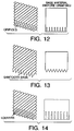
- FIGS 6-14 illustrate several different embodiments of the invention.
- Figures 15 and 16 show graphical representations of results attained with the use of the invention and also when the invention is not employed and serve to illustrate the advantages of the use of the invention.
- the invention incorporates the discovery that the capacity of structured packing, such as when used in a rectification system, may be significantly increased if the gas flow resistance in the lower region of a structured packing section is reduced from that experienced in the major portion of the structured packing section. That is, the pressure drop associated with the gas or vapor entry into the structured packing section or brick is made to be less than the pressure drop which would be experienced if the configuration of the structured packing in this lower region had the same configuration as in the upper portion of the structured packing section.
- This localized reduction in gas flow resistance enables an increased flow of gas or vapor up through the structured packing section before the point is reached where the upward flow of gas impedes the downward flow of liquid through the section so that flooding conditions are reached.
- the increased capacity of the structured packing section enables the use of less structured packing for any given separation thus reducing the cost of carrying out the separation.
- the invention may be used in any distillation, absorption or stripping process, which may employ structured packing.
- One particularly advantageous use is in cryogenic rectification such as in the cryogenic rectification of air into nitrogen, oxygen and/or argon components.
- cryogenic rectification such as in the cryogenic rectification of air into nitrogen, oxygen and/or argon components.
- other useful distillation processes include oil fractionations, hydrocarbon separations and alcohol distillations.
- Distillation columns are used for a wide variety of separations in industry. Over the past decade, structured packing has become the internal of choice due to its low pressure drop and high mass transfer efficiency when compared to conventional distillation trays or random packing.
- Structured packing comprises vertically oriented sheets with the corrugations at an angle to the vertical axis such as is shown in Figure 1. Sheets are arranged such that the corrugation direction of adjacent sheets is reversed as shown in Figure 2.
- the packing is installed in the column as layers which are generally between 6 and 12 inches in height. Adjacent layers are rotated around a vertical axis to enhance mixing as shown in Figure 3.
- each layer may be comprised of a single section or brick of packing formed by fixing individual sheets together using rods that pierce all of the sheets.
- each packing layer may be made from several sections that fit together to fill the cross-section of the containing vessel.
- Figure 4 illustrates a single section layer and a layer with 10 sections.
- the complete packed bed comprises multiple layers of the packing, the number of layers being set by the height of packing required to perform the separation.
- Figure 5 shows a view through the packing denoted as XX on Figure 3 inclined at the same angle to the vertical as the corrugations.
- the corrugations are characterized by the crimp height, h, and the base length, b.
- the corrugation pattern shown is sharp (saw-tooth) but it may also be rounded (sinusoidal).
- the sheets touch each other at contact points along the peaks and valleys of the corrugation, denoted by A in Figure 5.
- Variations include the use and size of perforations in the packing sheets and the type of surface texture applied to the sheets. Packing is made in several sizes as characterized by the specific surface area (area of surface per unit volume. Different sizes are achieved by variation of the crimp height, h, and the base length, b. For example, reducing the crimp height increases the surface area per unit volume. The use of higher specific surface area packing reduces the height of packing required for a given separation but allowable fluid velocities are decreased. Thus a larger cross- sectional area for flow is required.
- the height of the packing is calculated from the product of the number of equilibrium stages required and the height of an equivalent theoretical plate (HETP).
- HETP is a measure of the mass transfer efficiency.
- the cross-sectional area of the column is dictated primarily by the vapor and liquid flowrates and densities.
- columns are designed to operate between 80 and 90 percent of the flowrates at the flood point for the packing in question.
- the flood point may be considered as the maximum vapor flowrate at a fixed liquid flowrate at which the column is operable. Physically, it occurs when the vapor loading is such that the liquid can no longer flow countercurrently under gravity against the vapor.
- higher specific surface area packings have a lower flood point because the dimensions available for flow between the sheets are smaller.
- the invention comprises a configured structured packing section that reduces the pressure drop associated with the vapor entry into the packing section and thus eases the passage of liquid from the section.
- gas and vapor flowing through the structured packing section are used synonymously herein.
- This pressure drop reduction is achieved by configuring the structured packing sheets in the region at the base of each section which is between 0.1 and 20 times h in height (denoted by region L in Figure 6) such that the geometry in the base region, L, differs from that of the bulk region (denoted by U in Figure 6) which is defined as that region above the base region.
- a cylindrical brick or section is shown in Figure 6 but any brick shape may be used with the invention.
- Base region L may comprise up to the lower 50 percent of the height H of the structured packing brick or section and preferably comprises the lower 5 percent of the height H and most preferably comprises the lower 2.5 percent of the height H.
- Structured packing such as is shown in Figures 1-4 comprises corrugated sheets stacked vertically and usually connected using one or more rods that extend through the packing to make a section. These sections are typically 6 to 12 inches in height.
- a packing layer is equal to the section height and extends over the column cross-section which is typically circular.
- the packing sheets are substantially uniform in height and have straight cut edges such that the base and top of each section or brick are essentially flat. The bricks are stacked one on top of the other.
- Figure 7 illustrates in an edge view one embodiment of the invention.
- sheets that constitute the section are cut to the required length and then alternately staggered in a vertical direction when placed together to form the brick.
- one half of the sheets extend to the bottom of the section and the other half to the top of the section. That is, within the base region a first plurality of structured packing sheets extend beyond the edges of a second plurality of structured packing sheets in alternating sequence.
- This staggering effectively doubles the hydraulic radius, R h , in the base region over that in the bulk region except for the staggered portion at the upper part of the bulk-region.
- the height of the stagger, h s is within the range 0.1h to 20h, preferably within the range 0.5h to 2h.
- FIG. 8 Another staggering embodiment comprises cutting the structured packing sheets such that half have a reduced height. These are then stacked as shown in Figure 8.
- the embodiment illustrated in Figure 8 is a particularly preferred embodiment of the invention.
- the degree of stagger, h s is similar to the embodiment illustrated in Figure 7.
- the top of the packing is flat whereas in the previously described embodiment the top is also staggered.
- This staggering arrangement illustrated in Figure 8 effectively doubles the hydraulic radius, R h , in the base region over that in the bulk region.
- FIG. 9 shows a packing in perspective and edge views with all sheets having a flattened base.
- Figure 10 shows a packing in perspective and edge views having corrugations with a reduced crimp height at the base.
- Figure 11 there is illustrated an embodiment in perspective and face views wherein the base region has the same crimp height but with corrugations at a steeper angle. This reduces the actual gas velocity and thus the pressure drop in the gas region of the packing.
- Figures 12-14 there are illustrated embodiments wherein the fractional open area of the material is significantly increased over the bulk of the packing preferably by at least 20 percent. This is achieved through increased perforations, louvers, notches or slots. All of the above will allow passage of vapor through them, resulting in a more vertical flow of vapor and a lower pressure drop in the base region than in the bulk region.
- Figures 15 and 16 show the results from a packing with a specific surface area of approximately 500 m2/m3. The results are expressed as the pressure gradient over the bed versus the air capacity factor, Cv, defined by; Cv u g ⁇ g ⁇ L - ⁇ g where u g is the superficial air velocity based on the column cross-sectional area (ft/s) ⁇ L is the water density (1b/ft3 ⁇ g is the air density (1b/ft3 Case 1 represents the pressure drop over the bed of the original, unmodified packing, stacked in the conventional manner. Cases 2-4 show the pressure gradient over the bed with a horizontal spacing between bricks of 1h, 2h and 3h respectively.
- Case 5 shows the pressure drop over the bed with the packing sheets alternately staggered between 0.8 and 1.2 times the crimp height, h, as described by Figure 7, where the crimp height was 0.26 inch.
- the pressure gradient in all cases was taken as the bed pressure drop divided by the height of the original unmodified packing.
- the form of the pressure drop versus capacity factor data is typical of structured packings. The rate of increase in pressure drop increases with air flow. At around 0.5 inches of water per foot the pressure drop begins to increase rapidly due to a sharp increase in liquid hold-up. This indicates the onset of loading.
- the flood point is usually defined as occurring at a pressure drop of 1 to 2 inches of water per foot.
- the gas flow resistance in the base region of the structured packing section will be at least 10 percent, and preferably at least 20 percent, less than the gas flow resistance in the bulk region of the structured packing section.
Landscapes
- Chemical & Material Sciences (AREA)
- Physics & Mathematics (AREA)
- Engineering & Computer Science (AREA)
- Thermal Sciences (AREA)
- Chemical Kinetics & Catalysis (AREA)
- Mechanical Engineering (AREA)
- General Engineering & Computer Science (AREA)
- Organic Chemistry (AREA)
- Vaporization, Distillation, Condensation, Sublimation, And Cold Traps (AREA)
- Separation By Low-Temperature Treatments (AREA)
- Physical Or Chemical Processes And Apparatus (AREA)
- Polishing Bodies And Polishing Tools (AREA)
Abstract
Description
- This invention relates to structured packing and its use for carrying out separation of a fluid mixture by countercurrent vapor-liquid contact such as the cryogenic rectification of air.
- Distillation of a fluid mixture, e.g. air, into two or more portions enriched in a respective mixture component has generally been carried out employing one or more distillation or rectification columns which employ trays as the column internals or mass transfer elements. Recently there has developed an increasing use of structured packing as mass transfer elements in rectification columns because structured packing has a much lower pressure drop than does trays.
- While structured packing has advantages over conventional trays in the operation of a distillation column, the cost of the packing is generally higher than that of the trays. The volume of packing required to effect a separation depends on the packing height and the column diameter. The latter is set by the capacity of the packing or equivalently by the flooding point wherein gas or vapor and liquid no longer effectively flow in countercurrent contact. A structured packing which has increased capacity thus enabling increased column throughput before reaching flood conditions would be very desirable.
- Accordingly, it is an object of this invention to provide structured packing which enables improved performance over conventional structured packing.
- It is another object of this invention to provide a structured packing for use in a rectification column having increased capacity enabling increased column throughput before reaching flood conditions.
- The above and other objects which will become apparent to one skilled in the art upon a reading of this disclosure are attained by the present invention, one aspect of which is:
- A structured packing section comprising a plurality of vertically oriented structured packing sheets defining a section height, said section having a base region, comprising up to the lower 50 percent of the section height, and a bulk region comprising at least some of the remainder of the section height, wherein the structured packing sheets in the base region have a configuration such that the resistance to gas flow between the sheets in the base region is less than the resistance to gas flow between the sheets in the bulk region.
- Another aspect of the invention is:
A method for countercurrent flow of gas and liquid comprising passing liquid down and passing gas up a structured packing section comprising a plurality of vertically oriented structured packing sheets defining a section height, said section having a base region, comprising up to the lower 50 percent of the section height, and a bulk region comprising at least some of the remainder of the section height, and passing gas through the base region with lower gas flow resistance than gas passing through the bulk region. - The term "column" as used herein means a distillation or fractionation column or zone, i.e., a contacting column or zone wherein liquid and vapor phases are countercurrently contacted to effect separation of a fluid mixture, as, for example, by contacting of the vapor and liquid phases on packing elements. For a further discussion of distillation columns see the Chemical Engineers' Handbook, Fifth Edition, edited by R. H. Perry and C. H. Chilton, McGraw-Hill Book Company, New York, Section 13, "Distillation" B. D. Smith, et al., page 13-3 The Continuous Distillation Process. Vapor and liquid contacting separation processes depend on the difference in vapor pressures for the components. The high vapor pressure (or more volatile or low boiling) component will tend to concentrate in the vapor phase whereas the low vapor pressure (or less volatile or high boiling) component will tend to concentrate in the liquid phase. Distillation is the separation process whereby heating of a liquid mixture can be used to concentrate the volatile component(s) in the vapor phase and thereby the less volatile component(s) in the liquid phase. Partial condensation is the separation process whereby cooling of a vapor mixture can be used to concentrate the volatile component(s) in the vapor phase and thereby the less volatile component(s) in the liquid phase. Rectification, or continuous distillation, is the separation process that combines successive partial vaporizations and condensations as obtained by a countercurrent treatment of the vapor and liquid phases. The countercurrent contacting of the vapor and liquid phases can be adiabatic or nonadiabatic and can include integral (stagewise) or differential (continuous) contact between the phases. Separation process arrangements that utilize the principles of rectification to separate mixtures are often interchangeably termed rectification columns, distillation columns, or fractionation columns. Cryogenic rectification is rectification carried out, at least in part, at temperatures below 150°K.
- As used herein, the term "packing" means any solid or hollow body of predetermined configuration, size and shape used as column internals to provide surface area for the liquid to allow mass transfer at the liquid-vapor interface daring countercurrent flow of the two phases.
- As used herein, the term "HETP" means the height of packing over which a composition change is achieved which is equivalent to the composition change achieved by a theoretical plate.
- As used herein, the term "theoretical plate" means a contact process between vapor and liquid such that the exiting vapor and liquid streams are in equilibrium.
- As used herein, the term "structured packing" means packing wherein individual members have specific orientation relative to each other and to the column axis. Examples of structured packing are disclosed in U.S. Patent No. 4,186,159-Huber, U.S. Patent No. 4,296,050-Meier, U.S. Patent No. 4,929,388-Lockett, et al. and U.S. 5,132,056-Lockett, et al.
- As used herein the term "gas flow resistance" means the pressure drop experienced by the gas per unit height of packing expresed, for example, as mbar/m.
- As used herein the term "section height" means the height of a packing section or unit comprised of vertically oriented sheets. This height is the difference between the horizontal plane where the vapor enters the packing unit and the horizontal plane where the vapor exits the packing unit. Each packing unit can be termed a "brick" and stacked bricks comprise the packed column.
- Figures 1-5 are representations of general structured packing characteristics which are presented so as to better explain the novel structured packing arrangement of the invention and its use within a column.
- Figures 6-14 illustrate several different embodiments of the invention.
- Figures 15 and 16 show graphical representations of results attained with the use of the invention and also when the invention is not employed and serve to illustrate the advantages of the use of the invention.
- In general the invention incorporates the discovery that the capacity of structured packing, such as when used in a rectification system, may be significantly increased if the gas flow resistance in the lower region of a structured packing section is reduced from that experienced in the major portion of the structured packing section. That is, the pressure drop associated with the gas or vapor entry into the structured packing section or brick is made to be less than the pressure drop which would be experienced if the configuration of the structured packing in this lower region had the same configuration as in the upper portion of the structured packing section. This localized reduction in gas flow resistance enables an increased flow of gas or vapor up through the structured packing section before the point is reached where the upward flow of gas impedes the downward flow of liquid through the section so that flooding conditions are reached. The increased capacity of the structured packing section enables the use of less structured packing for any given separation thus reducing the cost of carrying out the separation.
- The invention may be used in any distillation, absorption or stripping process, which may employ structured packing. One particularly advantageous use is in cryogenic rectification such as in the cryogenic rectification of air into nitrogen, oxygen and/or argon components. Examples of other useful distillation processes include oil fractionations, hydrocarbon separations and alcohol distillations.
- The invention will be described in detail with reference to the drawings.
- Distillation columns are used for a wide variety of separations in industry. Over the past decade, structured packing has become the internal of choice due to its low pressure drop and high mass transfer efficiency when compared to conventional distillation trays or random packing.
- Structured packing comprises vertically oriented sheets with the corrugations at an angle to the vertical axis such as is shown in Figure 1. Sheets are arranged such that the corrugation direction of adjacent sheets is reversed as shown in Figure 2. The packing is installed in the column as layers which are generally between 6 and 12 inches in height. Adjacent layers are rotated around a vertical axis to enhance mixing as shown in Figure 3. In small columns each layer may be comprised of a single section or brick of packing formed by fixing individual sheets together using rods that pierce all of the sheets. In large columns, each packing layer may be made from several sections that fit together to fill the cross-section of the containing vessel. Figure 4 illustrates a single section layer and a layer with 10 sections. The complete packed bed comprises multiple layers of the packing, the number of layers being set by the height of packing required to perform the separation. Figure 5 shows a view through the packing denoted as XX on Figure 3 inclined at the same angle to the vertical as the corrugations. The corrugations are characterized by the crimp height, h, and the base length, b. The corrugation pattern shown is sharp (saw-tooth) but it may also be rounded (sinusoidal). The sheets touch each other at contact points along the peaks and valleys of the corrugation, denoted by A in Figure 5.
- While all corrugated sheet structured packings share the above-described features, there are a large number of variations available commercially. Variations include the use and size of perforations in the packing sheets and the type of surface texture applied to the sheets. Packing is made in several sizes as characterized by the specific surface area (area of surface per unit volume. Different sizes are achieved by variation of the crimp height, h, and the base length, b. For example, reducing the crimp height increases the surface area per unit volume. The use of higher specific surface area packing reduces the height of packing required for a given separation but allowable fluid velocities are decreased. Thus a larger cross- sectional area for flow is required.
- The height of the packing is calculated from the product of the number of equilibrium stages required and the height of an equivalent theoretical plate (HETP). The HETP is a measure of the mass transfer efficiency. The cross-sectional area of the column is dictated primarily by the vapor and liquid flowrates and densities. Typically, columns are designed to operate between 80 and 90 percent of the flowrates at the flood point for the packing in question. The flood point may be considered as the maximum vapor flowrate at a fixed liquid flowrate at which the column is operable. Physically, it occurs when the vapor loading is such that the liquid can no longer flow countercurrently under gravity against the vapor. Generally higher specific surface area packings have a lower flood point because the dimensions available for flow between the sheets are smaller.
- The invention comprises a configured structured packing section that reduces the pressure drop associated with the vapor entry into the packing section and thus eases the passage of liquid from the section. The terms gas and vapor flowing through the structured packing section are used synonymously herein. This pressure drop reduction is achieved by configuring the structured packing sheets in the region at the base of each section which is between 0.1 and 20 times h in height (denoted by region L in Figure 6) such that the geometry in the base region, L, differs from that of the bulk region (denoted by U in Figure 6) which is defined as that region above the base region. A cylindrical brick or section is shown in Figure 6 but any brick shape may be used with the invention. Base region L may comprise up to the lower 50 percent of the height H of the structured packing brick or section and preferably comprises the lower 5 percent of the height H and most preferably comprises the lower 2.5 percent of the height H.
- Different configurations of the structured packing to enable the gas flow resistance in the base region to be less than the gas flow resistance in the bulk region may be used in the practice of the invention. These types of configurations may be used separately or in combination and four examples are listed below:
- (i) Make the hydraulic radius, Rh, in the base region greater than in the bulk region, preferably to be 1.1 times its value in the bulk region, where Rh is given by;
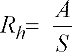
- (ii) Make the crimp height in the base region less than in the bulk region, preferably to be less than 90 percent of that of the bulk region.
- (iii) Make the corrugations in the base region steeper, preferably by at least 5 degrees, in the base region than in the bulk region of the packing.
- (iv) Make the fractional open area of the packing material greater, preferably by 20 percent or more, in the base region compared to that in the bulk region of the packing section. By "fractional open area" it is meant in a metal sheet of unit area, the area of the sheet from which metal has been removed, for example, by perforation.
- These four types of arrangements wherein the structured packing in the base region of the section differs from the structured packing in the bulk region of the section to effect a lower gas flow resistance in the base region than in the bulk region will be described below in greater detail including illustrations of some specific embodiments.
- Structured packing such as is shown in Figures 1-4 comprises corrugated sheets stacked vertically and usually connected using one or more rods that extend through the packing to make a section. These sections are typically 6 to 12 inches in height. A packing layer is equal to the section height and extends over the column cross-section which is typically circular. In conventional practice the packing sheets are substantially uniform in height and have straight cut edges such that the base and top of each section or brick are essentially flat. The bricks are stacked one on top of the other.
- Figure 7 illustrates in an edge view one embodiment of the invention. In this embodiment sheets that constitute the section are cut to the required length and then alternately staggered in a vertical direction when placed together to form the brick. In this manner, one half of the sheets extend to the bottom of the section and the other half to the top of the section. That is, within the base region a first plurality of structured packing sheets extend beyond the edges of a second plurality of structured packing sheets in alternating sequence. This staggering effectively doubles the hydraulic radius, Rh, in the base region over that in the bulk region except for the staggered portion at the upper part of the bulk-region. The height of the stagger, hs, is within the range 0.1h to 20h, preferably within the range 0.5h to 2h. The most optimum value will depend on the specific application. Increasing the stagger height will tend to increase the flood point. Offsetting this is a reduction in the specific surface area in the base region and a reduction in the load bearing capability of the packing. The latter will strongly depend on the material of construction, the specific surface area of the packing, the thickness of the sheets and the possible requirement of supporting column internals on the top of the packing.
- Another staggering embodiment comprises cutting the structured packing sheets such that half have a reduced height. These are then stacked as shown in Figure 8. The embodiment illustrated in Figure 8 is a particularly preferred embodiment of the invention. The degree of stagger, hs, is similar to the embodiment illustrated in Figure 7. In this embodiment the top of the packing is flat whereas in the previously described embodiment the top is also staggered. This staggering arrangement illustrated in Figure 8 effectively doubles the hydraulic radius, Rh, in the base region over that in the bulk region.
- Another means for reducing the pressure drop associated with the gas entry into the brick is to arrange for the gas to take a less tortuous flow path. This may be achieved by reducing the number of contact points (indicated by A in Figure 5) between neighboring sheets, thus opening the structure and promoting a more vertical flow path. This reduces both the gas velocity and path length for the gas relative to the unmodified packing. Examples of this embodiment are shown in Figures 9 to 11. Figure 9 shows a packing in perspective and edge views with all sheets having a flattened base. Figure 10 shows a packing in perspective and edge views having corrugations with a reduced crimp height at the base.
- In Figure 11 there is illustrated an embodiment in perspective and face views wherein the base region has the same crimp height but with corrugations at a steeper angle. This reduces the actual gas velocity and thus the pressure drop in the gas region of the packing.
- In Figures 12-14 there are illustrated embodiments wherein the fractional open area of the material is significantly increased over the bulk of the packing preferably by at least 20 percent. This is achieved through increased perforations, louvers, notches or slots. All of the above will allow passage of vapor through them, resulting in a more vertical flow of vapor and a lower pressure drop in the base region than in the bulk region.
- In Figures 15 and 16 there is presented data which exemplifies the advantages of the invention over that of conventional structured packing arrangements and also the surprising results obtained with the practice of the invention when compared with the results experienced when the structured packing sections or bricks are spaced from one another. The ineffectiveness of spacing the bricks and the efficacy of the invention was demonstrated by experimental work performed on a 12 inch glass column using 3 bricks of packing. Each brick was approximately 11 inches in height and 11.75 inches in diameter. Each brick constituted one layer in the column. In these tests, the capacity of various packings was tested by measuring the pressure drop over the bed at a fixed water load of 7.4 gallons per minute (gpm) and various air flows. Figures 15 and 16 show the results from a packing with a specific surface area of approximately 500 m2/m3. The results are expressed as the pressure gradient over the bed versus the air capacity factor, Cv, defined by;
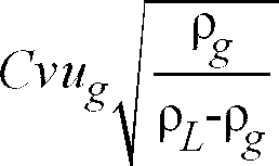
ρ L is the water density (1b/ft³
ρ g is the air density (1b/ft³
Case 1 represents the pressure drop over the bed of the original, unmodified packing, stacked in the conventional manner. Cases 2-4 show the pressure gradient over the bed with a horizontal spacing between bricks of 1h, 2h and 3h respectively. The spacing was achieved using four metal spacers that allowed greater than 95 percent open area for gas flow in the space between the bricks.Case 5 shows the pressure drop over the bed with the packing sheets alternately staggered between 0.8 and 1.2 times the crimp height, h, as described by Figure 7, where the crimp height was 0.26 inch. The pressure gradient in all cases was taken as the bed pressure drop divided by the height of the original unmodified packing. The form of the pressure drop versus capacity factor data is typical of structured packings. The rate of increase in pressure drop increases with air flow. At around 0.5 inches of water per foot the pressure drop begins to increase rapidly due to a sharp increase in liquid hold-up. This indicates the onset of loading. The flood point is usually defined as occurring at a pressure drop of 1 to 2 inches of water per foot. - Referring to Figure 15, no appreciable difference is discernible between the conventional case with no spacing between bricks (Case 1) and the cases with spacing (Cases 2, 3 and 4). In contrast, the staggered structured packing section of the invention gave a dramatic improvement in capacity of about 17 percent as shown in Figure 16 (Case 5). The improvement was such that the experimental system employed could not provide sufficient air flow to flood the packing. Over the whole range of air flow the pressure drop was consistently lower than for the conventional packing. At a pressure drop of 0.45 inches of water per foot the packing section of the invention with alternating structured packing sheets having different lengths in the base region, i.e. the staggered arrangement, had a Cv of 0.23ft/s versus a value of 0.195ft/s for the conventional packing. This represents over a 17 percent increase in capacity.
- Another series of tests were performed with a packing of a higher specific surface area (approximately 800 m²/m³) In these experiments, conventional packing was first tested. A second series of tests were then performed with the sheets at the base of one brick flattened over a base region equivalent to 5 times the crimp height. In this case it was observed that the brick with the flattened base had a greater capacity than the conventional bricks. This was indicated by the fact that as the air rate was increased, significant build-up of liquid around the periphery occurred on all of the bricks except on the brick with the flattened base.
- In the practice of the invention it is expected that the gas flow resistance in the base region of the structured packing section will be at least 10 percent, and preferably at least 20 percent, less than the gas flow resistance in the bulk region of the structured packing section.
- Although it is preferable that the conditions and arrangements described herein for the base region and the bulk region occur throughout these respective regions, the particular conditions and arrangements may occur in only portions of these respective regions.
- Although the invention has been described in detail with reference to certain preferred embodiments, those skilled in the art will recognize that there are other embodiments of the invention within the spirit and the scope of the claims.
Claims (18)
- A structured packing section comprising a plurality of vertically oriented structured packing sheets defining a section height, said section having a base region, comprising up to the lower 50 percent of the section height, and a bulk region comprising at least some of the remainder of the section height, wherein the structured packing sheets in the base region have a configuration such that the resistance to gas flow between the sheets in the base region is less than the resistance to gas flow between the sheets in the bulk region.
- The structured packing section of Claim 1 wherein the hydraulic radius in the base region exceeds the hydraulic radius in the bulk region.
- The structured packing section of Claim 2 wherein within the base region a first plurality of structured packing sheets extend beyond the edges of a second plurality of structured packing sheets in alternating sequence.
- The structured packing section of Claim 1 wherein the crimp height of the structured packing sheets in the base region is less than the crimp height of the structured packing sheets in the bulk region.
- The structured packing section of Claim 1 wherein the structured packing sheets have corrugations characterized by the corrugations in the base region being steeper than the corrugations in the bulk region.
- The structured packing section of Claim 1 wherein the fractional open area of the packing section in the base region exceeds the fractional open area of the packing section in the bulk region.
- The structured packing section of Claim 6 wherein the packing sheets in the base region contain perforations.
- The structured packing section of Claim 6 wherein the packing sheets in the base region have serrated edges.
- The structured packing section of Claim 1 wherein the bulk region comprises all of the remainder of the section height.
- The structured packing section of Claim 1 wherein the base region comprises the lower 5 percent of the section height.
- The structured packing section of claim 1 wherein the base region comprises the lower 2.5 percent of the section height.
- A method for countercurrent flow of gas and liquid comprising passing liquid down and passing gas up a structured packing section comprising a plurality of vertically oriented structured packing sheets defining a section height, said section having a base region, comprising up to the lower 50 percent of the section height, and a bulk region comprising at least some of the remainder of the section height, and passing gas through the base region with lower gas flow resistance than gas passing through the bulk region.
- The method of Claim 12 wherein the countercurrent flow of gas and liquid occurs while carrying out cryogenic rectification in a column.
- The method of Claim 13 wherein the gas passing up the structured packing section comprises at least two components from the group consisting of nitrogen, oxygen and argon, and the liquid passing down the structured packing section comprises at least two components from the group consisting of nitrogen, oxygen and argon.
- The method of Claim 12 wherein the gas flow resistance of the gas flowing through the base region is at least 10 percent less than the gas flow resistance of the gas flowing through the bulk region.
- The method of Claim 12 wherein the base region comprises the lower 5 percent of the section height.
- The method of Claim 12 wherein the base region comprises the lower 2.5 percent of the section height.
- The method of Claim 12 wherein the bulk region comprises all of the remainder of the section height.
Applications Claiming Priority (2)
| Application Number | Priority Date | Filing Date | Title |
|---|---|---|---|
| US31749994A | 1994-10-04 | 1994-10-04 | |
| US317499 | 1994-10-04 |
Publications (2)
| Publication Number | Publication Date |
|---|---|
| EP0707885A1 true EP0707885A1 (en) | 1996-04-24 |
| EP0707885B1 EP0707885B1 (en) | 1999-06-02 |
Family
ID=23233926
Family Applications (1)
| Application Number | Title | Priority Date | Filing Date |
|---|---|---|---|
| EP95115585A Revoked EP0707885B1 (en) | 1994-10-04 | 1995-10-03 | Structured packing with improved capacity for rectification systems |
Country Status (9)
| Country | Link |
|---|---|
| US (1) | US5632934A (en) |
| EP (1) | EP0707885B1 (en) |
| JP (1) | JP3205494B2 (en) |
| KR (1) | KR100233787B1 (en) |
| CN (1) | CN1091646C (en) |
| BR (1) | BR9504265A (en) |
| CA (1) | CA2159752C (en) |
| DE (1) | DE69510000T2 (en) |
| ES (1) | ES2132489T3 (en) |
Cited By (18)
| Publication number | Priority date | Publication date | Assignee | Title |
|---|---|---|---|---|
| EP0858830A1 (en) * | 1997-02-13 | 1998-08-19 | Praxair Technology, Inc. | Corrugated packing with improved capacity and high mass transfer efficiency |
| RU2124394C1 (en) * | 1996-12-16 | 1999-01-10 | Выборнов Вячеслав Георгиевич | Nozzle member for mass transfer and separation apparatuses |
| EP0916400A1 (en) * | 1996-01-24 | 1999-05-19 | Praxair Technology, Inc. | Distillation column employing structured packing which reduces wall flow |
| RU2136363C1 (en) * | 1995-11-29 | 1999-09-10 | Зульцер Хемтех Аг | Packing for high-pressure counterflow column and high-pressure column |
| EP0992282A1 (en) * | 1998-10-02 | 2000-04-12 | Praxair Technology, Inc. | Cryogenic rectification system with high strength and high capacity packing |
| EP0995958A3 (en) * | 1998-10-21 | 2000-10-18 | Praxair Technology, Inc. | Method to avoid flooding in a cryogenic rectification column |
| WO2001062409A1 (en) * | 2000-02-25 | 2001-08-30 | Linde Aktiengesellschaft | Method for production of a packing for material and heat exchange |
| DE10010810A1 (en) * | 2000-03-08 | 2001-09-13 | Montz Gmbh Julius | Liquid distributor used in packing columns for distillation, absorption, gas scrubbing and other similar technical processes has at least one layer in a column with a specific surface area larger than the layer lying above and below it |
| WO2001068239A1 (en) * | 2000-03-17 | 2001-09-20 | L'air Liquide, Societe Anonyme A Directoire Et Conseil De Surveillance Pour L'etude Et L'exploitation Des Procedes Georges Claude | Packing module, method for making same, and fluid treating apparatus comprising a corresponding packing |
| EP1275435A1 (en) | 2001-07-14 | 2003-01-15 | Linde Aktiengesellschaft | Ordered packing for mass and heat transfer |
| FR2827527A1 (en) * | 2001-07-20 | 2003-01-24 | Air Liquide | Module for interface between two cross-corrugated packing modules, useful in fluid treatment column in air distillation unit, comprises bands of sheet metal, with alternating corrugations in fluid circulation direction |
| WO2003008092A1 (en) * | 2001-07-14 | 2003-01-30 | Linde Aktiengesellschaft | Ordered packing for mass and heat transfer |
| KR100398813B1 (en) * | 2001-08-31 | 2003-09-29 | (주)에이엠티퍼시픽 | Tower internals Structured packing which is using distillatory apparatus |
| FR2854579A1 (en) * | 2003-05-09 | 2004-11-12 | Air Liquide | Distillation plant, preferably for cryogenic air separation, has at least one column section containing structured linings with at least one modified interface |
| EP1506822A1 (en) * | 2003-08-12 | 2005-02-16 | Linde Aktiengesellschaft | Method and apparatus for making an ordered packing |
| DE102006005112A1 (en) * | 2006-02-04 | 2007-08-09 | Hewitech Gmbh & Co. Kg | Plastic foil for installation element for use in installation in ripple condenser, particularly cooling tower for cooling purposes or to install in ground for drinage purpose, has two surface area where one of two surface area has openings |
| WO2015121594A2 (en) | 2014-02-14 | 2015-08-20 | L'air Liquide, Societe Anonyme Pour L'etude Et L'exploitation Des Procedes Georges Claude | Device and method for separating air by cryogenic distillation |
| EP4748491A1 (en) | 2024-11-26 | 2026-05-27 | L'air Liquide, Societe Anonyme Pour L'etude Et L'exploitation Des Procedes Georges Claude | Structured packing module, column containing a module and air separation apparatus containing a module |
Families Citing this family (46)
| Publication number | Priority date | Publication date | Assignee | Title |
|---|---|---|---|---|
| GB9522086D0 (en) | 1995-10-31 | 1996-01-03 | Ici Plc | Fluid-fluid contacting apparatus |
| CN1237116A (en) * | 1997-07-04 | 1999-12-01 | 屈尼有限公司 | Internal components of a mass exchange column |
| FR2771025B1 (en) * | 1997-11-17 | 2000-01-28 | Air Liquide | CORRUGATED STRIP FOR CROSS-CORRUGATED TRIM AND ITS APPLICATION TO ON-BOARD DISTILLATION COLUMNS |
| DE69907616T2 (en) | 1998-12-28 | 2004-03-11 | Nippon Sanso Corp. | Vapor-liquid contactor, cryogenic air separation unit and process for gas separation |
| US6713158B2 (en) | 1999-06-25 | 2004-03-30 | The Boc Group, Inc. | Structured packing |
| US6509082B1 (en) | 1999-06-25 | 2003-01-21 | The Boc Group, Inc. | Structured packing |
| DE19936380A1 (en) * | 1999-08-03 | 2001-02-08 | Basf Ag | Orderly packing for heat and material exchange |
| US6478290B2 (en) | 1999-12-09 | 2002-11-12 | Praxair Technology, Inc. | Packing for mass transfer column |
| US6212907B1 (en) | 2000-02-23 | 2001-04-10 | Praxair Technology, Inc. | Method for operating a cryogenic rectification column |
| US6517058B1 (en) * | 2000-03-02 | 2003-02-11 | Sandkuhl Clay Works, Inc. | Fill packs for use in heat and mass transfer devices |
| US6378332B1 (en) | 2000-09-07 | 2002-04-30 | Praxair Technology, Inc. | Packing with low contacting crimp pattern |
| US6314756B1 (en) | 2000-09-07 | 2001-11-13 | Praxair Technology, Inc. | Structured packing with asymmetric crimp pattern |
| GB0022688D0 (en) * | 2000-09-15 | 2000-11-01 | Ingen Process Ltd | Removal and disposal of sour reservoir components |
| US6321567B1 (en) * | 2000-10-06 | 2001-11-27 | Praxair Technology, Inc. | Structured packing system for reduced distillation column height |
| US6751986B2 (en) | 2000-12-22 | 2004-06-22 | The Bog Group, Inc. | Structured packing |
| DE10124386A1 (en) * | 2001-05-18 | 2002-11-28 | Basf Ag | Distillation column for mixtures, with toxic component, has packing with variable inner geometry to form lower bubbling layer with dispersed gas phase and an upper film layer with a continuous gas phase |
| CN1274401C (en) * | 2001-07-06 | 2006-09-13 | 液体空气乔治洛德方法利用和研究的具有监督和管理委员会的有限公司 | Belts for filling modules, corresponding modules and equipment |
| US20030086846A1 (en) * | 2001-11-05 | 2003-05-08 | Adusei George Y. | Monolith stacking configuration for improved flooding |
| US20030116871A1 (en) * | 2001-12-21 | 2003-06-26 | Steven Ringo | Structured packing |
| RU2232632C1 (en) * | 2003-01-30 | 2004-07-20 | Саратовское акционерное производственно-коммерческое открытое общество "Нефтемаш" - САПКОН | Regular packing |
| US6991222B2 (en) * | 2003-03-31 | 2006-01-31 | George Amir Meski | Structured packing with increased capacity |
| SG115648A1 (en) * | 2003-03-31 | 2005-10-28 | Air Prod & Chem | Structured packing with increased capacity |
| FR2855770A1 (en) * | 2003-06-05 | 2004-12-10 | Air Liquide | Corrugated strip, used for liquid treatment module, especially air distillation column, has flat sides of corrugations made with angled slats |
| FR2878454A1 (en) * | 2004-11-29 | 2006-06-02 | Air Liquide | Pack elements for exchange of materials between gas and liquids and heat exchange, comprises rectangular, corrugated lamellae in vertical plane |
| DE202005004859U1 (en) * | 2005-03-26 | 2006-08-03 | 2H Kunststoff Gmbh | Contact body for an evaporative humidifier or material exchanger for humidifying, cooling and / or purifying air |
| US7267329B2 (en) * | 2005-07-27 | 2007-09-11 | Air Products And Chemicals, Inc. | Alternating conventional and high capacity packing within the same section of an exchange column |
| FR2929134B1 (en) | 2008-03-28 | 2010-12-31 | Air Liquide | METHOD FOR MANUFACTURING A CROSS-CROSSOVER TRIM |
| FR2938776A1 (en) * | 2008-11-24 | 2010-05-28 | Air Liquide | CROSS-CROSSOVER TRIM AND COLUMN INCORPORATING SUCH A TRIM |
| TWI495505B (en) * | 2009-03-18 | 2015-08-11 | Sulzer Chemtech Ag | Method and apparatus for the purification of fluids |
| FR2947188A1 (en) * | 2009-06-24 | 2010-12-31 | Air Liquide | Process for distilling fluid using cross-corrugated packing module comprising stack of sheet strips, which comprise edges extending perpendicular to the general orientation and corrugations that alternately form first and second main peaks |
| EP2753414A1 (en) | 2011-09-07 | 2014-07-16 | Carbon Engineering Limited Partnership | Target gas capture |
| FR2996148B1 (en) * | 2012-10-03 | 2015-11-06 | Euroslot Kdss France | FLUSHING MEMBER STRUCTURE FOR COLUMN FOR CONTACTING FLUIDS |
| US9295925B2 (en) | 2012-12-11 | 2016-03-29 | Praxair Technology, Inc. | Structured packing and method |
| US9625221B2 (en) * | 2013-02-04 | 2017-04-18 | Koch-Glitsch, Lp | Liquid distribution device utilizing packed distribution troughs and a mass transfer column and process involving same |
| US9266047B2 (en) | 2013-07-25 | 2016-02-23 | Exxonmobil Research And Engineering Company | Mist eliminator configuration for droplet removal in fouling service |
| FR3037507A1 (en) | 2015-06-16 | 2016-12-23 | Ifp Energies Now | COLLECTOR FOR HEAT EXCHANGE COLUMN AND / OR MATERIAL COMPRISING A GARNISHING AND AT LEAST ONE FREE FALL ZONE |
| CN105771873B (en) * | 2016-03-30 | 2018-10-23 | 中建安装工程有限公司 | A kind of structured packing of efficient mass transfer |
| US20180087834A1 (en) * | 2016-09-26 | 2018-03-29 | Air Products And Chemicals, Inc. | Exchange Column With Corrugated Structured Packing And Method For Use Thereof |
| US20180087835A1 (en) * | 2016-09-26 | 2018-03-29 | Air Products And Chemicals, Inc. | Exchange Column With Corrugated Structured Packing And Method For Use Thereof |
| WO2018153551A1 (en) * | 2017-02-22 | 2018-08-30 | Linde Aktiengesellschaft | Packing material for a substance exchange column and method for producing a packing material |
| JP7239488B2 (en) * | 2017-05-02 | 2023-03-14 | コーク-グリッシュ,リミティド パートナーシップ | Structured packing module for mass transfer columns |
| US10578357B2 (en) | 2017-08-25 | 2020-03-03 | Praxair Technology, Inc. | Annular divided wall column with ring shaped collectors and distributers for an air separation unit |
| US10684071B2 (en) | 2017-08-25 | 2020-06-16 | Praxair Technology, Inc. | Annular divided wall column for an air separation unit |
| JP7175793B2 (en) * | 2019-02-19 | 2022-11-21 | 大陽日酸株式会社 | Packed tower and packing |
| JP7618966B2 (en) * | 2020-05-15 | 2025-01-22 | 株式会社Ihi | Gas-liquid contactor |
| EP3932512A1 (en) | 2020-07-02 | 2022-01-05 | Sulzer Management AG | Structured packing bed for high pressure mass transfer and/or heat exchange applications |
Citations (6)
| Publication number | Priority date | Publication date | Assignee | Title |
|---|---|---|---|---|
| FR2390201A1 (en) * | 1977-05-12 | 1978-12-08 | Sulzer Ag | SHEET MATERIAL PADDING ELEMENT WITH RUNOFF SURFACES FOR COLUMNS FOR EXCHANGE OF MATERIALS OR ISOTOPES AND FOR HEAT EXCHANGE |
| SU1183158A1 (en) * | 1983-04-07 | 1985-10-07 | Предприятие П/Я Р-6273 | Package for heat-mass-transfer apparatus |
| SU1230654A1 (en) * | 1983-07-14 | 1986-05-15 | Предприятие П/Я А-1059 | Packing for heat-mass-exchange apparatus |
| EP0467395A1 (en) * | 1990-07-20 | 1992-01-22 | Praxair Technology, Inc. | Variable density structured packing cryogenic distillation system |
| DE4122369C1 (en) * | 1991-07-05 | 1992-10-22 | Rainer Richter Gmbh, 5439 Hof, De | Packaging used for heat and mass transfer between liq. and gas - consists of corrugated or folded foil, plate or mat-like packaging elements in zones, in which profiles are inclined to longitudinal axis, etc. |
| EP0644389A1 (en) * | 1993-09-17 | 1995-03-22 | The Boc Group, Inc. | Distillation column utilizing structured packing |
Family Cites Families (28)
| Publication number | Priority date | Publication date | Assignee | Title |
|---|---|---|---|---|
| US2485849A (en) * | 1946-04-12 | 1949-10-25 | American Blower Corp | Heat exchanger or cooling tower |
| US2793017A (en) * | 1954-10-04 | 1957-05-21 | Dow Chemical Co | Apparatus for distributing falling liquid in thin films |
| US2783982A (en) * | 1955-01-27 | 1957-03-05 | Kahl Carl H William | Evaporative cooler with tower air flow |
| US3265550A (en) * | 1957-07-10 | 1966-08-09 | Munters & Co Carl | Process of making a packing unit of moisture absorbent cellulosic material |
| US3081987A (en) * | 1959-07-13 | 1963-03-19 | George W Meek | Cooling towers |
| SE224921C1 (en) * | 1959-12-23 | 1969-02-18 | ||
| US3132190A (en) * | 1961-10-12 | 1964-05-05 | Baltimore Aircoil Co Inc | Heat exchange apparatus |
| FR1377537A (en) * | 1963-09-26 | 1964-11-06 | Tissmetal Lionel Dupont | packing element for exchange columns between two fluids |
| SE307964B (en) * | 1964-03-24 | 1969-01-27 | C Munters | |
| SE325589B (en) * | 1967-02-21 | 1970-07-06 | C G Munters | |
| SE328319B (en) * | 1967-07-07 | 1970-09-14 | C Munters | |
| US3801419A (en) * | 1971-07-20 | 1974-04-02 | Munters Ab Carl | Corrugated sheet member with a reinforcing edge extending lengthwise of the corrugations |
| SU700773A1 (en) * | 1976-06-01 | 1979-11-30 | Ленинградское Отделение Всесоюзного Государственного Ордена Ленина И Ордена Октябрьской Революции Проектного Института "Теплоэлектропроект" | Counter-current cooling tower spinkler |
| US4052491A (en) * | 1976-06-25 | 1977-10-04 | Research-Cottrell, Inc. | Modular gas and liquid contact means |
| CH617357A5 (en) * | 1977-05-12 | 1980-05-30 | Sulzer Ag | |
| JPS5854162Y2 (en) * | 1979-07-27 | 1983-12-09 | 三菱樹脂株式会社 | Filler for gas-liquid contact |
| EP0138401B1 (en) * | 1983-10-15 | 1991-05-29 | Albert Frederick Wigley | Gas/liquid contact device |
| US4950430A (en) * | 1986-12-01 | 1990-08-21 | Glitsch, Inc. | Structured tower packing |
| US4838913A (en) * | 1988-02-10 | 1989-06-13 | Union Carbide Corporation | Double column air separation process with hybrid upper column |
| US4929399A (en) * | 1988-03-17 | 1990-05-29 | Union Carbide Industrial Gases Technology Inc. | Structured column packing with liquid holdup |
| DE3907573A1 (en) * | 1989-03-09 | 1990-09-20 | Sulzer Ag | MULTIPLE-PULL WHEEL PACK |
| DE3909995C1 (en) * | 1989-03-25 | 1990-08-30 | Schott Glaswerke, 6500 Mainz, De | |
| US5063000A (en) * | 1989-05-03 | 1991-11-05 | Mix Thomas W | Packing elements |
| US5019144A (en) * | 1990-01-23 | 1991-05-28 | Union Carbide Industrial Gases Technology Corporation | Cryogenic air separation system with hybrid argon column |
| US5055239A (en) * | 1990-11-15 | 1991-10-08 | Munters Corporation | Liquid and gas contact apparatus |
| FR2675568B1 (en) * | 1991-04-19 | 1993-07-16 | Air Liquide | PROCESS FOR THE CRYOGENIC SEPARATION OF MIXTURES CONTAINING OXYGEN AND TRIMS ORGANIZED FOR THE IMPLEMENTATION OF THIS PROCESS. |
| US5132056A (en) * | 1991-05-28 | 1992-07-21 | Union Carbide Industrial Gases Technology Corporation | Structured column packing with improved turndown and method |
| JPH06312101A (en) * | 1993-04-28 | 1994-11-08 | Hitachi Ltd | Packing material and tower for gas-liquid contact |
-
1995
- 1995-09-29 CN CN95117234A patent/CN1091646C/en not_active Expired - Lifetime
- 1995-10-02 KR KR1019950033652A patent/KR100233787B1/en not_active Expired - Lifetime
- 1995-10-03 BR BR9504265A patent/BR9504265A/en not_active IP Right Cessation
- 1995-10-03 JP JP27823195A patent/JP3205494B2/en not_active Expired - Lifetime
- 1995-10-03 EP EP95115585A patent/EP0707885B1/en not_active Revoked
- 1995-10-03 ES ES95115585T patent/ES2132489T3/en not_active Expired - Lifetime
- 1995-10-03 DE DE69510000T patent/DE69510000T2/en not_active Revoked
- 1995-10-03 CA CA002159752A patent/CA2159752C/en not_active Expired - Lifetime
-
1996
- 1996-03-22 US US08/620,202 patent/US5632934A/en not_active Expired - Lifetime
Patent Citations (6)
| Publication number | Priority date | Publication date | Assignee | Title |
|---|---|---|---|---|
| FR2390201A1 (en) * | 1977-05-12 | 1978-12-08 | Sulzer Ag | SHEET MATERIAL PADDING ELEMENT WITH RUNOFF SURFACES FOR COLUMNS FOR EXCHANGE OF MATERIALS OR ISOTOPES AND FOR HEAT EXCHANGE |
| SU1183158A1 (en) * | 1983-04-07 | 1985-10-07 | Предприятие П/Я Р-6273 | Package for heat-mass-transfer apparatus |
| SU1230654A1 (en) * | 1983-07-14 | 1986-05-15 | Предприятие П/Я А-1059 | Packing for heat-mass-exchange apparatus |
| EP0467395A1 (en) * | 1990-07-20 | 1992-01-22 | Praxair Technology, Inc. | Variable density structured packing cryogenic distillation system |
| DE4122369C1 (en) * | 1991-07-05 | 1992-10-22 | Rainer Richter Gmbh, 5439 Hof, De | Packaging used for heat and mass transfer between liq. and gas - consists of corrugated or folded foil, plate or mat-like packaging elements in zones, in which profiles are inclined to longitudinal axis, etc. |
| EP0644389A1 (en) * | 1993-09-17 | 1995-03-22 | The Boc Group, Inc. | Distillation column utilizing structured packing |
Non-Patent Citations (2)
| Title |
|---|
| SOVIET INVENTIONS ILLUSTRATED Section Ch Week 8617, 9 December 1986 Derwent World Patents Index; Class J01, AN 86-111979 * |
| SOVIET INVENTIONS ILLUSTRATED Section Ch Week 8652, 31 December 1986 Derwent World Patents Index; Class J01, AN 86-345588 * |
Cited By (25)
| Publication number | Priority date | Publication date | Assignee | Title |
|---|---|---|---|---|
| RU2136363C1 (en) * | 1995-11-29 | 1999-09-10 | Зульцер Хемтех Аг | Packing for high-pressure counterflow column and high-pressure column |
| EP0916400A1 (en) * | 1996-01-24 | 1999-05-19 | Praxair Technology, Inc. | Distillation column employing structured packing which reduces wall flow |
| RU2124394C1 (en) * | 1996-12-16 | 1999-01-10 | Выборнов Вячеслав Георгиевич | Nozzle member for mass transfer and separation apparatuses |
| EP0858830A1 (en) * | 1997-02-13 | 1998-08-19 | Praxair Technology, Inc. | Corrugated packing with improved capacity and high mass transfer efficiency |
| EP0992282A1 (en) * | 1998-10-02 | 2000-04-12 | Praxair Technology, Inc. | Cryogenic rectification system with high strength and high capacity packing |
| EP0995958A3 (en) * | 1998-10-21 | 2000-10-18 | Praxair Technology, Inc. | Method to avoid flooding in a cryogenic rectification column |
| WO2001062409A1 (en) * | 2000-02-25 | 2001-08-30 | Linde Aktiengesellschaft | Method for production of a packing for material and heat exchange |
| DE10010810A1 (en) * | 2000-03-08 | 2001-09-13 | Montz Gmbh Julius | Liquid distributor used in packing columns for distillation, absorption, gas scrubbing and other similar technical processes has at least one layer in a column with a specific surface area larger than the layer lying above and below it |
| WO2001068239A1 (en) * | 2000-03-17 | 2001-09-20 | L'air Liquide, Societe Anonyme A Directoire Et Conseil De Surveillance Pour L'etude Et L'exploitation Des Procedes Georges Claude | Packing module, method for making same, and fluid treating apparatus comprising a corresponding packing |
| FR2806325A1 (en) * | 2000-03-17 | 2001-09-21 | Air Liquide | PACKING MODULE, ITS MANUFACTURING PROCESS, AND FLUID (S) TREATMENT APPARATUS INCLUDING A CORRESPONDING PADDING |
| WO2003008092A1 (en) * | 2001-07-14 | 2003-01-30 | Linde Aktiengesellschaft | Ordered packing for mass and heat transfer |
| EP1275435A1 (en) | 2001-07-14 | 2003-01-15 | Linde Aktiengesellschaft | Ordered packing for mass and heat transfer |
| FR2827527A1 (en) * | 2001-07-20 | 2003-01-24 | Air Liquide | Module for interface between two cross-corrugated packing modules, useful in fluid treatment column in air distillation unit, comprises bands of sheet metal, with alternating corrugations in fluid circulation direction |
| KR100398813B1 (en) * | 2001-08-31 | 2003-09-29 | (주)에이엠티퍼시픽 | Tower internals Structured packing which is using distillatory apparatus |
| FR2854579A1 (en) * | 2003-05-09 | 2004-11-12 | Air Liquide | Distillation plant, preferably for cryogenic air separation, has at least one column section containing structured linings with at least one modified interface |
| WO2004102095A1 (en) | 2003-05-09 | 2004-11-25 | L'air Liquide, Societe Anonyme A Directoire Et Conseil De Surveillance Pour L'etude Et L'exploitation Des Procedes Georges Claud | Distillation installation comprising columns with corrugated-crossed structured packings and method of increasing the capacity of a distillation installation |
| CN100368748C (en) * | 2003-05-09 | 2008-02-13 | 乔治洛德方法研究和开发液化空气有限公司 | Distillation apparatus and method for increasing capacity of distillation apparatus |
| US7210324B2 (en) | 2003-08-12 | 2007-05-01 | Linde Aktiengesellschaft | Process and apparatus for producing an ordered packing |
| EP1506822A1 (en) * | 2003-08-12 | 2005-02-16 | Linde Aktiengesellschaft | Method and apparatus for making an ordered packing |
| DE102006005112A1 (en) * | 2006-02-04 | 2007-08-09 | Hewitech Gmbh & Co. Kg | Plastic foil for installation element for use in installation in ripple condenser, particularly cooling tower for cooling purposes or to install in ground for drinage purpose, has two surface area where one of two surface area has openings |
| WO2015121594A2 (en) | 2014-02-14 | 2015-08-20 | L'air Liquide, Societe Anonyme Pour L'etude Et L'exploitation Des Procedes Georges Claude | Device and method for separating air by cryogenic distillation |
| WO2015121593A2 (en) | 2014-02-14 | 2015-08-20 | L'air Liquide, Societe Anonyme Pour L'etude Et L'exploitation Des Procedes Georges Claude | Column for separating air by cryogenic distillation, air separation device comprising such a column and method for producing such a column |
| US10473392B2 (en) | 2014-02-14 | 2019-11-12 | L'air Liquide Societe Anonyme Pour L'etude Et L'exploitation Des Procedes Georges Claude | Column for separating air by cryogenic distillation, air separation device comprising such a column and method for producing such a column |
| EP4748491A1 (en) | 2024-11-26 | 2026-05-27 | L'air Liquide, Societe Anonyme Pour L'etude Et L'exploitation Des Procedes Georges Claude | Structured packing module, column containing a module and air separation apparatus containing a module |
| WO2026114923A1 (en) | 2024-11-26 | 2026-06-04 | L'air Liquide, Societe Anonyme Pour L'etude Et L'exploitation Des Procedes Georges Claude | Structured packing module, column containing a module and air separation apparatus containing a module |
Also Published As
| Publication number | Publication date |
|---|---|
| CN1131056A (en) | 1996-09-18 |
| US5632934A (en) | 1997-05-27 |
| CA2159752C (en) | 2001-02-20 |
| DE69510000T2 (en) | 1999-11-04 |
| KR100233787B1 (en) | 1999-12-01 |
| JP3205494B2 (en) | 2001-09-04 |
| JPH08206492A (en) | 1996-08-13 |
| CA2159752A1 (en) | 1996-04-05 |
| DE69510000D1 (en) | 1999-07-08 |
| EP0707885B1 (en) | 1999-06-02 |
| ES2132489T3 (en) | 1999-08-16 |
| BR9504265A (en) | 1996-10-22 |
| KR960013410A (en) | 1996-05-22 |
| CN1091646C (en) | 2002-10-02 |
Similar Documents
| Publication | Publication Date | Title |
|---|---|---|
| EP0707885B1 (en) | Structured packing with improved capacity for rectification systems | |
| EP0858366B1 (en) | Structured packing | |
| US6598861B2 (en) | Optimal corrugated structured packing | |
| TW450827B (en) | Mixed-resistance structured packing, exchange tower containing said packing and method for assembling same, process for cryogenic air separation by using same, method and system for reducing HETP | |
| US4304738A (en) | Packing Material and apparatus | |
| EP0858830A1 (en) | Corrugated packing with improved capacity and high mass transfer efficiency | |
| JP2002326031A (en) | Structured packing | |
| EP0992282B2 (en) | Cryogenic rectification system with high strength and high capacity packing | |
| CA2312214C (en) | Structured packing | |
| US6378332B1 (en) | Packing with low contacting crimp pattern | |
| EP0337150B1 (en) | Structured column packing with liquid holdup | |
| EP1195563B1 (en) | Structured packing system for reduced distillation column height | |
| US7267329B2 (en) | Alternating conventional and high capacity packing within the same section of an exchange column | |
| AU4260700A (en) | Structured packing | |
| KR102100544B1 (en) | Exchange column with corrugated structured packing and method for use thereof | |
| EP1186342B1 (en) | Structured packing with asymmetric crimp pattern | |
| US20180087834A1 (en) | Exchange Column With Corrugated Structured Packing And Method For Use Thereof | |
| MXPA98001209A (en) | Packaging with improved capacity and high efficiency transfer of m | |
| EP3299086A1 (en) | Exchange column with corrugated structured packing and method for use thereof |
Legal Events
| Date | Code | Title | Description |
|---|---|---|---|
| PUAI | Public reference made under article 153(3) epc to a published international application that has entered the european phase |
Free format text: ORIGINAL CODE: 0009012 |
|
| AK | Designated contracting states |
Kind code of ref document: A1 Designated state(s): BE CH DE ES FR GB IT LI NL SE |
|
| 17P | Request for examination filed |
Effective date: 19960621 |
|
| 17Q | First examination report despatched |
Effective date: 19980525 |
|
| GRAG | Despatch of communication of intention to grant |
Free format text: ORIGINAL CODE: EPIDOS AGRA |
|
| GRAG | Despatch of communication of intention to grant |
Free format text: ORIGINAL CODE: EPIDOS AGRA |
|
| GRAH | Despatch of communication of intention to grant a patent |
Free format text: ORIGINAL CODE: EPIDOS IGRA |
|
| GRAH | Despatch of communication of intention to grant a patent |
Free format text: ORIGINAL CODE: EPIDOS IGRA |
|
| GRAA | (expected) grant |
Free format text: ORIGINAL CODE: 0009210 |
|
| ITF | It: translation for a ep patent filed | ||
| AK | Designated contracting states |
Kind code of ref document: B1 Designated state(s): BE CH DE ES FR GB IT LI NL SE |
|
| REG | Reference to a national code |
Ref country code: CH Ref legal event code: EP |
|
| REF | Corresponds to: |
Ref document number: 69510000 Country of ref document: DE Date of ref document: 19990708 |
|
| ET | Fr: translation filed | ||
| REG | Reference to a national code |
Ref country code: CH Ref legal event code: NV Representative=s name: KIRKER & CIE SA |
|
| REG | Reference to a national code |
Ref country code: ES Ref legal event code: FG2A Ref document number: 2132489 Country of ref document: ES Kind code of ref document: T3 |
|
| PLBQ | Unpublished change to opponent data |
Free format text: ORIGINAL CODE: EPIDOS OPPO |
|
| PLBI | Opposition filed |
Free format text: ORIGINAL CODE: 0009260 |
|
| PLBQ | Unpublished change to opponent data |
Free format text: ORIGINAL CODE: EPIDOS OPPO |
|
| PLBI | Opposition filed |
Free format text: ORIGINAL CODE: 0009260 |
|
| PLBF | Reply of patent proprietor to notice(s) of opposition |
Free format text: ORIGINAL CODE: EPIDOS OBSO |
|
| 26 | Opposition filed |
Opponent name: L'AIR LIQUIDE, SOCIETE ANONYME POUR L'ETUDE ET L'E Effective date: 20000301 Opponent name: SULZER CHEMTECH AG Effective date: 20000228 |
|
| 26 | Opposition filed |
Opponent name: LINDE AKTIENGESELLSCHAFT Effective date: 20000302 Opponent name: L'AIR LIQUIDE, SOCIETE ANONYME POUR L'ETUDE ET L'E Effective date: 20000301 Opponent name: SULZER CHEMTECH AG Effective date: 20000228 |
|
| NLR1 | Nl: opposition has been filed with the epo |
Opponent name: L'AIR LIQUIDE, SOCIETE ANONYME POUR L'ETUDE ET L'E Opponent name: SULZER CHEMTECH AG |
|
| NLR1 | Nl: opposition has been filed with the epo |
Opponent name: LINDE AKTIENGESELLSCHAFT Opponent name: L'AIR LIQUIDE, SOCIETE ANONYME POUR L'ETUDE ET L'E Opponent name: SULZER CHEMTECH AG |
|
| PLBF | Reply of patent proprietor to notice(s) of opposition |
Free format text: ORIGINAL CODE: EPIDOS OBSO |
|
| PLBF | Reply of patent proprietor to notice(s) of opposition |
Free format text: ORIGINAL CODE: EPIDOS OBSO |
|
| PLBF | Reply of patent proprietor to notice(s) of opposition |
Free format text: ORIGINAL CODE: EPIDOS OBSO |
|
| PGFP | Annual fee paid to national office [announced via postgrant information from national office to epo] |
Ref country code: SE Payment date: 20010920 Year of fee payment: 7 Ref country code: FR Payment date: 20010920 Year of fee payment: 7 Ref country code: DE Payment date: 20010920 Year of fee payment: 7 |
|
| PGFP | Annual fee paid to national office [announced via postgrant information from national office to epo] |
Ref country code: GB Payment date: 20010921 Year of fee payment: 7 |
|
| PGFP | Annual fee paid to national office [announced via postgrant information from national office to epo] |
Ref country code: CH Payment date: 20010924 Year of fee payment: 7 |
|
| PGFP | Annual fee paid to national office [announced via postgrant information from national office to epo] |
Ref country code: NL Payment date: 20010925 Year of fee payment: 7 |
|
| PGFP | Annual fee paid to national office [announced via postgrant information from national office to epo] |
Ref country code: BE Payment date: 20011010 Year of fee payment: 7 |
|
| PGFP | Annual fee paid to national office [announced via postgrant information from national office to epo] |
Ref country code: ES Payment date: 20011108 Year of fee payment: 7 |
|
| REG | Reference to a national code |
Ref country code: GB Ref legal event code: IF02 |
|
| RDAH | Patent revoked |
Free format text: ORIGINAL CODE: EPIDOS REVO |
|
| RDAG | Patent revoked |
Free format text: ORIGINAL CODE: 0009271 |
|
| STAA | Information on the status of an ep patent application or granted ep patent |
Free format text: STATUS: PATENT REVOKED |
|
| 27W | Patent revoked |
Effective date: 20020124 |
|
| GBPR | Gb: patent revoked under art. 102 of the ep convention designating the uk as contracting state |
Free format text: 20020124 |
|
| REG | Reference to a national code |
Ref country code: CH Ref legal event code: PL |
|
| NLR2 | Nl: decision of opposition |