EP0138401B1 - Gas/liquid contact device - Google Patents
Gas/liquid contact device Download PDFInfo
- Publication number
- EP0138401B1 EP0138401B1 EP84306329A EP84306329A EP0138401B1 EP 0138401 B1 EP0138401 B1 EP 0138401B1 EP 84306329 A EP84306329 A EP 84306329A EP 84306329 A EP84306329 A EP 84306329A EP 0138401 B1 EP0138401 B1 EP 0138401B1
- Authority
- EP
- European Patent Office
- Prior art keywords
- sheet
- gas
- depressions
- cells
- adjacent
- Prior art date
- Legal status (The legal status is an assumption and is not a legal conclusion. Google has not performed a legal analysis and makes no representation as to the accuracy of the status listed.)
- Expired
Links
Images


Classifications
-
- B—PERFORMING OPERATIONS; TRANSPORTING
- B01—PHYSICAL OR CHEMICAL PROCESSES OR APPARATUS IN GENERAL
- B01J—CHEMICAL OR PHYSICAL PROCESSES, e.g. CATALYSIS OR COLLOID CHEMISTRY; THEIR RELEVANT APPARATUS
- B01J19/00—Chemical, physical or physico-chemical processes in general; Their relevant apparatus
- B01J19/32—Packing elements in the form of grids or built-up elements for forming a unit or module inside the apparatus for mass or heat transfer
-
- F—MECHANICAL ENGINEERING; LIGHTING; HEATING; WEAPONS; BLASTING
- F28—HEAT EXCHANGE IN GENERAL
- F28F—DETAILS OF HEAT-EXCHANGE AND HEAT-TRANSFER APPARATUS, OF GENERAL APPLICATION
- F28F25/00—Component parts of trickle coolers
- F28F25/02—Component parts of trickle coolers for distributing, circulating, and accumulating liquid
- F28F25/08—Splashing boards or grids, e.g. for converting liquid sprays into liquid films; Elements or beds for increasing the area of the contact surface
- F28F25/087—Vertical or inclined sheets; Supports or spacers
-
- B—PERFORMING OPERATIONS; TRANSPORTING
- B01—PHYSICAL OR CHEMICAL PROCESSES OR APPARATUS IN GENERAL
- B01J—CHEMICAL OR PHYSICAL PROCESSES, e.g. CATALYSIS OR COLLOID CHEMISTRY; THEIR RELEVANT APPARATUS
- B01J2219/00—Chemical, physical or physico-chemical processes in general; Their relevant apparatus
- B01J2219/32—Details relating to packing elements in the form of grids or built-up elements for forming a unit of module inside the apparatus for mass or heat transfer
- B01J2219/322—Basic shape of the elements
- B01J2219/32203—Sheets
- B01J2219/3221—Corrugated sheets
-
- B—PERFORMING OPERATIONS; TRANSPORTING
- B01—PHYSICAL OR CHEMICAL PROCESSES OR APPARATUS IN GENERAL
- B01J—CHEMICAL OR PHYSICAL PROCESSES, e.g. CATALYSIS OR COLLOID CHEMISTRY; THEIR RELEVANT APPARATUS
- B01J2219/00—Chemical, physical or physico-chemical processes in general; Their relevant apparatus
- B01J2219/32—Details relating to packing elements in the form of grids or built-up elements for forming a unit of module inside the apparatus for mass or heat transfer
- B01J2219/322—Basic shape of the elements
- B01J2219/32203—Sheets
- B01J2219/32213—Plurality of essentially parallel sheets
-
- B—PERFORMING OPERATIONS; TRANSPORTING
- B01—PHYSICAL OR CHEMICAL PROCESSES OR APPARATUS IN GENERAL
- B01J—CHEMICAL OR PHYSICAL PROCESSES, e.g. CATALYSIS OR COLLOID CHEMISTRY; THEIR RELEVANT APPARATUS
- B01J2219/00—Chemical, physical or physico-chemical processes in general; Their relevant apparatus
- B01J2219/32—Details relating to packing elements in the form of grids or built-up elements for forming a unit of module inside the apparatus for mass or heat transfer
- B01J2219/322—Basic shape of the elements
- B01J2219/32203—Sheets
- B01J2219/32248—Sheets comprising areas that are raised or sunken from the plane of the sheet
-
- B—PERFORMING OPERATIONS; TRANSPORTING
- B01—PHYSICAL OR CHEMICAL PROCESSES OR APPARATUS IN GENERAL
- B01J—CHEMICAL OR PHYSICAL PROCESSES, e.g. CATALYSIS OR COLLOID CHEMISTRY; THEIR RELEVANT APPARATUS
- B01J2219/00—Chemical, physical or physico-chemical processes in general; Their relevant apparatus
- B01J2219/32—Details relating to packing elements in the form of grids or built-up elements for forming a unit of module inside the apparatus for mass or heat transfer
- B01J2219/322—Basic shape of the elements
- B01J2219/32203—Sheets
- B01J2219/32255—Other details of the sheets
-
- B—PERFORMING OPERATIONS; TRANSPORTING
- B01—PHYSICAL OR CHEMICAL PROCESSES OR APPARATUS IN GENERAL
- B01J—CHEMICAL OR PHYSICAL PROCESSES, e.g. CATALYSIS OR COLLOID CHEMISTRY; THEIR RELEVANT APPARATUS
- B01J2219/00—Chemical, physical or physico-chemical processes in general; Their relevant apparatus
- B01J2219/32—Details relating to packing elements in the form of grids or built-up elements for forming a unit of module inside the apparatus for mass or heat transfer
- B01J2219/324—Composition or microstructure of the elements
- B01J2219/32483—Plastics
Definitions
- the invention relates to a gas-liquid contact packing device according to the preamble of claim 1.
- a pack for a cooling tower which pack comprises a plurality of similar sheets of a plastics material formed, e.g. by vacuum forming, with a series of corrugations so that when the sheets are assembled together they define a series of tubular cells through which liquid is intended to pass under gravity while gas is passed upwardly through the cells so that heat is transferred from one to the other.
- a pack for a cooling tower which pack comprises a plurality of similar sheets of a plastics material formed, e.g. by vacuum forming, with a series of corrugations so that when the sheets are assembled together they define a series of tubular cells through which liquid is intended to pass under gravity while gas is passed upwardly through the cells so that heat is transferred from one to the other.
- the invention provides a gas-liquid contact packing device for enabling a film of liquid and a gaseous stream to be brought into contact to effect heat exchange therebetween, the pack comprising a plurality of sheets each of which is continuously corrugated to define a plurality of parallel depressions and is assembled with similar sheets to define a plurality of parallel tubular cells of substantially constant cross section, the cells being provided with angled projections arranged to impart rotary motion to the gas stream and the cells being formed with transverse ribs which form channels which interconnect adjacent cells to permit liquid flow between the cells, characterised in that the depressions in each sheet are V-shaped in cross section and have side walls which meet the side walls of adjoining depressions in the same sheet to provide rectilinear crests which meet the crests of adjacent sheets in substantially line contact, forming cells of substantially rectangular cross section.
- US-A-3485485 describes a cooling grid providing cells of rectangular cross section, but which is of very different construction from the device of the present invention.
- the angled projections extend continuously between two adjacent crests of the depressions, the angled projections being disposed on the sheet so that each of them has one end adjacent to a middle portion of an adjacent angled projection, and so that adjacent angled projections project from opposite sides of the sheet.
- the depressions preferably present a similar appearance on both sides of the sheet, the pair of walls which define each depression being disposed substantially at right angles with respect to one another and at an angle of around 45° with respect to the plane of the sheet.
- the transverse ribs may be of sinusoidal transverse cross-section so that they present a similar appearance on both sides of the packing sheet.
- the disposition of the angled projections on the packing sheet may be asymmetric. Angled projections are preferably formed in the walls of the depressions on both sides of the sheet.
- two identical packing sheets can be assembled together by turning one through 180° with respect to the other, whereupon at least some of the angled projections on one sheet lie adjacent to at least some of the angled projections on the other sheet to form in each rectangular section tubular cell means for imparting a rotary motion to gas passing through the cell.
- the sheets according to the present invention are continuously corrugated to form a plurlaity of parallel depressions or corrugations 9 which are V-shaped in cross-section as seen in the end view of Figure 2, the corrugations or depressions being mutually parallel and of equal size.
- the two flat walls 10 forming each corrugation or depression 9 are generally at right angles to one another and are such that they present the same appearance on both sides of the sheet.
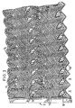
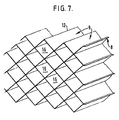
- the sheet 8 is formed with cylindrical or conical projections 11 extending from the tops and from the bottoms of some of the corrugations 9 and these cylindrica and conical projections 11 form, on the other side of the sheet, correspondingly shaped recesses 17 (see Figure 3) whereby on assembly of a plurality of the sheets to form a pack the projections can be located in the recesses of adjacent sheets to hold the sheets mutually positioned with the tops or crests 12 of the corrugations of each sheet in contact with the tops of the corrugations of adjacent sheets to form a pack consisting of a series of tubular cells of substantially square cross-section as shown in Figure 7. Since the sheets meet in substantially line contact, virtually the whole surface of the sheets is available for liquid/gas contact.
- ribs 13 extending at right angles to the corrugations 9.
- the ribs are substantially sinusoidal in cross-section as best can be seen in Figure 4 and extend over substantially the whole of the surface of the sheet.
- the surfaces of the sheets are formed at intervals with elongate or angled projections 14 which extend along the corrugations at an acute angle thereto, e.g. around 30°.
- Each elongate or angled projection 14 extends from the crests 12 on one side of a depression 9 to the crest 12 on the other side of the same depression.
- the elongate, angled projections 14 are formed to extend from both sides of the sheet (the projections on one side of the sheet forming corresponding depressions 18 (see Figure 3) on the other side of the sheet) and are so arranged in relation to one another that each projection has one end adjacent to a middle portion of an adjacent depression, and the middle portion of each projection is disposed adjacent to one end of a depression.
- These elongate projections are intended to impart a helical motion to gas passing through the tubular cells formed by an assembly of the sheets to improve gas/liquid contact.
- the elongate or angled projections 14 on the upper side of the sheet are indicated in full lines, while those on the underside of the sheet are indicated in dotted lines.
- the invention thus provides a packing, e.g. for a cooling tower, of high efficiency due to the fact that virtually the whole of the surfaces of the packing sheets are used for liquid/gas contact.
Description
- The invention relates to a gas-liquid contact packing device according to the preamble of claim 1.
- It is known to provide a pack for a cooling tower which pack comprises a plurality of similar sheets of a plastics material formed, e.g. by vacuum forming, with a series of corrugations so that when the sheets are assembled together they define a series of tubular cells through which liquid is intended to pass under gravity while gas is passed upwardly through the cells so that heat is transferred from one to the other. Such an arrangement which discloses the features of the preamble of claim 1 is described in GB-A-1351605.
- It is an object of the invention to provide a device for use in effecting contact between a gas and a flowing liquid film of the same general kind as described in GB-A-1351605 but which more efficiently utilizes the available area of the sheets of the pack for liquid/gas contact.
- The invention provides a gas-liquid contact packing device for enabling a film of liquid and a gaseous stream to be brought into contact to effect heat exchange therebetween, the pack comprising a plurality of sheets each of which is continuously corrugated to define a plurality of parallel depressions and is assembled with similar sheets to define a plurality of parallel tubular cells of substantially constant cross section, the cells being provided with angled projections arranged to impart rotary motion to the gas stream and the cells being formed with transverse ribs which form channels which interconnect adjacent cells to permit liquid flow between the cells, characterised in that the depressions in each sheet are V-shaped in cross section and have side walls which meet the side walls of adjoining depressions in the same sheet to provide rectilinear crests which meet the crests of adjacent sheets in substantially line contact, forming cells of substantially rectangular cross section.
- US-A-3485485 describes a cooling grid providing cells of rectangular cross section, but which is of very different construction from the device of the present invention.
- Preferably the angled projections extend continuously between two adjacent crests of the depressions, the angled projections being disposed on the sheet so that each of them has one end adjacent to a middle portion of an adjacent angled projection, and so that adjacent angled projections project from opposite sides of the sheet.
- The depressions preferably present a similar appearance on both sides of the sheet, the pair of walls which define each depression being disposed substantially at right angles with respect to one another and at an angle of around 45° with respect to the plane of the sheet. The transverse ribs may be of sinusoidal transverse cross-section so that they present a similar appearance on both sides of the packing sheet.
- The disposition of the angled projections on the packing sheet may be asymmetric. Angled projections are preferably formed in the walls of the depressions on both sides of the sheet.
- Preferably, two identical packing sheets can be assembled together by turning one through 180° with respect to the other, whereupon at least some of the angled projections on one sheet lie adjacent to at least some of the angled projections on the other sheet to form in each rectangular section tubular cell means for imparting a rotary motion to gas passing through the cell.
- An example of a gas/liquid contact packing device according to the invention will now be described with reference to the accompanying drawings, in which:-
- Figure 1 is a plan view of a packing sheet;
- Figure 2 is an end view of the packing sheet of Figure 1;
- Figure 3 is a scrap perspective view on an enlarged scale of part of the packing sheet of Figure 1;
- Figure 4 is a section taken on the line IV-IV of Figure 1;
- Figure 5 is a section taken on the line V-V of Figure 1;
- Figure 6 is a section taken on the line VI-VI of Figure 1; and
- Figure 7 shows a number of the packing sheets of Figures 1 to 6 assembled together to form a cooling tower pack.
- In the drawings there is shown a
packing sheet 8 for an evaporative cooling tower, the sheet being vacuum formed from plastics material and being of same general kind as is described in GB-A-1351605. - The sheets according to the present invention are continuously corrugated to form a plurlaity of parallel depressions or
corrugations 9 which are V-shaped in cross-section as seen in the end view of Figure 2, the corrugations or depressions being mutually parallel and of equal size. The twoflat walls 10 forming each corrugation ordepression 9 are generally at right angles to one another and are such that they present the same appearance on both sides of the sheet. - The
sheet 8 is formed with cylindrical orconical projections 11 extending from the tops and from the bottoms of some of thecorrugations 9 and these cylindrica andconical projections 11 form, on the other side of the sheet, correspondingly shaped recesses 17 (see Figure 3) whereby on assembly of a plurality of the sheets to form a pack the projections can be located in the recesses of adjacent sheets to hold the sheets mutually positioned with the tops orcrests 12 of the corrugations of each sheet in contact with the tops of the corrugations of adjacent sheets to form a pack consisting of a series of tubular cells of substantially square cross-section as shown in Figure 7. Since the sheets meet in substantially line contact, virtually the whole surface of the sheets is available for liquid/gas contact. - To ensure dispersal of the liquid evenly over the surface of the sheets they are formed with relatively
small ribs 13 extending at right angles to thecorrugations 9. The ribs are substantially sinusoidal in cross-section as best can be seen in Figure 4 and extend over substantially the whole of the surface of the sheet. Additionally the surfaces of the sheets are formed at intervals with elongate orangled projections 14 which extend along the corrugations at an acute angle thereto, e.g. around 30°. Each elongate orangled projection 14 extends from thecrests 12 on one side of adepression 9 to thecrest 12 on the other side of the same depression. The elongate,angled projections 14 are formed to extend from both sides of the sheet (the projections on one side of the sheet forming corresponding depressions 18 (see Figure 3) on the other side of the sheet) and are so arranged in relation to one another that each projection has one end adjacent to a middle portion of an adjacent depression, and the middle portion of each projection is disposed adjacent to one end of a depression. These elongate projections are intended to impart a helical motion to gas passing through the tubular cells formed by an assembly of the sheets to improve gas/liquid contact. In Figure 1 the elongate orangled projections 14 on the upper side of the sheet are indicated in full lines, while those on the underside of the sheet are indicated in dotted lines. - It will be noted from Figure 4 that the
crests 12 andvalleys 15 of the sheets forming the tops and the bottoms of the saw-tooth corrugations, are castellated by reason of the presence of the small transversesinusoidal ribs 13 so that on assembly of thesheets 8 to form a pack as shown in Figure 7, thetubular cells 16 of the pack are interconnected by substantially circular channels formed by pairs of thesinusoidal ribs 13 so that liquid overload of anycell 16 is prevented by transmission of the excess liquid to the adjacent cells. - The invention thus provides a packing, e.g. for a cooling tower, of high efficiency due to the fact that virtually the whole of the surfaces of the packing sheets are used for liquid/gas contact.
Claims (6)
- A gas-liquid contact packing device for enabling a film of liquid and a gaseous stream to be brought into contact to effect heat exchange therebetween, the pack comprising a plurality of sheets (8) each of which is continuously corrugated to define a plurality of parallel depressions (9) and is assembled with similar sheets to define a plurality of parallel tubular cells (16) of substantially constant cross section, the cells (16) being provided with angled projections (14) arranged to impart rotary motion to the gas stream and the cells being formed with transverse ribs (13) which form channels which interconnect adjacent cells to permit liquid flow between the cells, characterised in that the depressions (9) in each sheet (8) are V-shaped in cross section and have side walls (10) which meet the side walls (10) of adjoining depressions (9) in the same sheet to provide rectilinear crests (12) which meet the crests (12) of adjacent sheets (8) in substantially line contact, forming cells (16) of substantially rectangular cross section.
- A gas-liquid contact packing device according to claim 1, characterised in that the angled projections (14) extend continuously between two adjacent crests (12) of the depressions (9), the angled projections being so disposed on the sheet that each angled projection has one end adjacent to a middle portion of an adjacent angled projection and so that adjacent projections project from opposite sides of the sheet.
- A gas-liquid contact packing device according to claim 1 or claim 2, characterised in that the depressions (9) present a similar appearance on both sides of the sheet (8), and in that the pair of the walls (10) defining each depression are disposed substantially at right angles with respect to one another and are disposed at an angle of around 45 degrees with respect to the plane of the sheet.
- A gas-liquid contact packing device according to any preceding claim, characterised in that the transverse ribs (13) are of sinusoidal transverse cross-section so that they present a similar appearance on both sides of their sheet (8).
- A gas-liquid contact packing device according to any preceding claim, characterised in that the angled projections (14) are asymmetrically disposed on their sheet (8).
- A gas-liquid contact packing device according to any preceding claim, characterised in that the angled projections (14) are formed in the walls (10) of the depressions (9) on both sides of the sheet (8).
Priority Applications (1)
| Application Number | Priority Date | Filing Date | Title |
|---|---|---|---|
| AT84306329T ATE63999T1 (en) | 1983-10-15 | 1984-09-17 | DEVICE FOR GAS-LIQUID CONTACT. |
Applications Claiming Priority (4)
| Application Number | Priority Date | Filing Date | Title |
|---|---|---|---|
| GB8327664 | 1983-10-15 | ||
| GB838327664A GB8327664D0 (en) | 1983-10-15 | 1983-10-15 | Gas/liquid contact device |
| GB848405224A GB8405224D0 (en) | 1984-02-29 | 1984-02-29 | Gas/liquid contact device |
| GB8405224 | 1984-02-29 |
Publications (3)
| Publication Number | Publication Date |
|---|---|
| EP0138401A2 EP0138401A2 (en) | 1985-04-24 |
| EP0138401A3 EP0138401A3 (en) | 1985-10-09 |
| EP0138401B1 true EP0138401B1 (en) | 1991-05-29 |
Family
ID=26286919
Family Applications (1)
| Application Number | Title | Priority Date | Filing Date |
|---|---|---|---|
| EP84306329A Expired EP0138401B1 (en) | 1983-10-15 | 1984-09-17 | Gas/liquid contact device |
Country Status (5)
| Country | Link |
|---|---|
| US (1) | US4657711A (en) |
| EP (1) | EP0138401B1 (en) |
| CA (1) | CA1242387A (en) |
| DE (1) | DE3484640D1 (en) |
| IN (1) | IN161234B (en) |
Families Citing this family (18)
| Publication number | Priority date | Publication date | Assignee | Title |
|---|---|---|---|---|
| HU195314B (en) * | 1985-07-23 | 1988-04-28 | Villamos Ipari Kutato Intezet | Cooling insert for equipments carrying out heat and material exchange being between gaseous medium and fluid particularly for cooling towers and degasing units |
| DE3918483A1 (en) * | 1989-06-06 | 1990-12-13 | Munters Euroform Gmbh Carl | FILLED BODY |
| US5132056A (en) * | 1991-05-28 | 1992-07-21 | Union Carbide Industrial Gases Technology Corporation | Structured column packing with improved turndown and method |
| GB2258524B (en) * | 1991-08-08 | 1995-05-31 | Nat Power Plc | Film type packing element for use in cooling towers |
| US5454988A (en) * | 1994-01-12 | 1995-10-03 | Mitsubishi Corporation | Packing to be used in substance and/or heat exchanging tower |
| US5616289A (en) * | 1994-01-12 | 1997-04-01 | Mitsubishi Corporation | Substance and/or heat exchanging tower |
| CN1091646C (en) * | 1994-10-04 | 2002-10-02 | 普莱克斯技术有限公司 | Structured packing with improved capacity for rectification systems |
| US6206350B1 (en) * | 1998-11-25 | 2001-03-27 | Baltimore Aircoil Company, Inc. | Film fill-pack for inducement of spiraling gas flow in heat and mass transfer contact apparatus with self spacing fill-sheets |
| WO2001020241A2 (en) | 1999-09-15 | 2001-03-22 | Brentwood Industries, Inc. | Contact bodies and method and apparatus of making same |
| US8337934B2 (en) * | 2005-01-26 | 2012-12-25 | Hormel Foods Corporation | Method of making bacon pieces |
| DE202005004859U1 (en) * | 2005-03-26 | 2006-08-03 | 2H Kunststoff Gmbh | Contact body for an evaporative humidifier or material exchanger for humidifying, cooling and / or purifying air |
| KR100669032B1 (en) | 2006-08-21 | 2007-01-16 | 금호환경 주식회사 | Mixing apparatus for purifying air pollutants |
| DE102008008806A1 (en) * | 2008-02-12 | 2009-08-13 | Gea 2H Water Technologies Gmbh | Built-in element of a mounting package |
| US8968808B1 (en) | 2009-05-04 | 2015-03-03 | Hormel Foods Corporation | Pork belly processing for pre-cooked bacon |
| US9170054B2 (en) * | 2013-07-31 | 2015-10-27 | Baltimore Aircoil Company, Inc. | Cooling tower fill |
| US20160223262A1 (en) * | 2014-10-31 | 2016-08-04 | Baltimore Aircoil Company, Inc. | Cooling tower integrated inlet louver fill |
| EP3303871B1 (en) * | 2015-06-02 | 2021-02-17 | Apex Biomedical Company, LLC | Energy-absorbing structure with defined multi-phasic crush properties |
| US11433370B2 (en) * | 2019-12-20 | 2022-09-06 | Brentwood Industries, Inc. | Fill sheets and related fill pack assemblies |
Family Cites Families (13)
| Publication number | Priority date | Publication date | Assignee | Title |
|---|---|---|---|---|
| US1847216A (en) * | 1928-03-31 | 1932-03-01 | Garlock Packing Co | Packing |
| US2917292A (en) * | 1957-03-29 | 1959-12-15 | Dow Chemical Co | Assemblies of extended surface elements for gas-liquid contact apparatus |
| GB973746A (en) * | 1961-03-02 | 1964-10-28 | Jan Zemanek | Improvements in and relating to fillings for gas-liquid contact apparatus |
| AT281882B (en) | 1966-11-11 | 1970-06-10 | Heinz Faigle | Cooling grid as trickle installation, especially for cooling towers |
| US3540702A (en) * | 1968-08-22 | 1970-11-17 | Nippon Kokan Kk | Multi-wave packing material and a device for utilizing the same |
| AT321865B (en) * | 1970-04-27 | 1975-04-25 | Dl Veb Maschinen Und Appbau Gr | HIGH PERFORMANCE SA EXCHANGE PACK FOR COLUMNS |
| BE788776A (en) * | 1970-05-07 | 1973-01-02 | Serck Industries Ltd | LIQUID COOLING DEVICE |
| US3733063A (en) * | 1971-09-24 | 1973-05-15 | Marley Co | Chevron ribbed fill unit for water cooling tower |
| DE2262838A1 (en) * | 1971-12-28 | 1973-07-26 | Ilmateollisuus Oy | Contact plate assembly - for liquid - gas reaction |
| US3775234A (en) * | 1972-09-15 | 1973-11-27 | Improved Machinery Inc | Grid structure with waved strips having apexes with enlarged sections formed therein |
| SE385971B (en) * | 1973-12-20 | 1976-07-26 | Svenska Flaektfabriken Ab | CONTACT BODY FOR WATER AND AIR, MAINLY INTENDED FOR COOLING TOWER AND HUMIDIFIER |
| SE423152B (en) * | 1977-04-01 | 1982-04-13 | Svenska Flaektfabriken Ab | CONTACT BODY FOR LIQUID AND GAS CONSISTS OF A NUMBER OF VERTICALLY STANDING AND PARALLEL ORGANIZING AGAINST EACH SUPPORTING CONTACT PLATER |
| CH618006A5 (en) * | 1977-05-12 | 1980-06-30 | Sulzer Ag |
-
1984
- 1984-09-17 DE DE8484306329T patent/DE3484640D1/en not_active Expired - Fee Related
- 1984-09-17 EP EP84306329A patent/EP0138401B1/en not_active Expired
- 1984-09-17 US US06/651,280 patent/US4657711A/en not_active Expired - Fee Related
- 1984-09-18 IN IN727/DEL/84A patent/IN161234B/en unknown
- 1984-09-28 CA CA000464234A patent/CA1242387A/en not_active Expired
Also Published As
| Publication number | Publication date |
|---|---|
| EP0138401A3 (en) | 1985-10-09 |
| IN161234B (en) | 1987-10-24 |
| EP0138401A2 (en) | 1985-04-24 |
| CA1242387A (en) | 1988-09-27 |
| US4657711A (en) | 1987-04-14 |
| DE3484640D1 (en) | 1991-07-04 |
Similar Documents
| Publication | Publication Date | Title |
|---|---|---|
| EP0138401B1 (en) | Gas/liquid contact device | |
| EP0640037B1 (en) | Corrugated sheet assembly | |
| EP0671963B1 (en) | Nested packing for an exchange column | |
| US4668443A (en) | Contact bodies | |
| US4344899A (en) | Fill sheets for gas and liquid contact apparatus | |
| EP1004839B1 (en) | Film fill-pack for inducement of spiraling gas flow in heat and mass transfer contact apparatus with self spacing fill-sheets | |
| US5413872A (en) | Filling member | |
| US4562015A (en) | Open mesh fill assembly | |
| EP0454179B1 (en) | Tower packing grid | |
| EP0177474B1 (en) | Insertable contact body | |
| US5124087A (en) | Gas and liquid contact body | |
| EP0117077B1 (en) | Moisture eliminator | |
| EP0728035B1 (en) | Structured packing elements | |
| AU755288B2 (en) | Film fill-pack for inducement of spiraling gas flow in heat and mass transfer contact apparatus with self-spacing fill-sheets | |
| TWI778075B (en) | Structured packing module for mass transfer columns | |
| US5204027A (en) | Fluid contact panels | |
| RU96122497A (en) | FILLING FOR HIGH PRESSURE FLOW-ROW COLUMN AND HIGH PRESSURE COLUMN | |
| AU766548B2 (en) | Film fill-pack for inducement of spiraling gas flow in heat and mass transfer contact apparatus with self-spacing fill-sheets | |
| EP0033413B1 (en) | Vapour-liquid contact apparatus and method of fabricating grid-elements for use in such apparatus | |
| US5384178A (en) | Tube settler assembly | |
| EP0170402A1 (en) | Packing elements | |
| US20040173919A1 (en) | Strip for packing module, corresponding module and installation | |
| JPS6128402A (en) | Packing element | |
| CA1168149A (en) | Packing material and apparatus |
Legal Events
| Date | Code | Title | Description |
|---|---|---|---|
| PUAI | Public reference made under article 153(3) epc to a published international application that has entered the european phase |
Free format text: ORIGINAL CODE: 0009012 |
|
| AK | Designated contracting states |
Designated state(s): AT BE CH DE FR GB IT LI LU NL SE |
|
| PUAL | Search report despatched |
Free format text: ORIGINAL CODE: 0009013 |
|
| AK | Designated contracting states |
Designated state(s): AT BE CH DE FR GB IT LI LU NL SE |
|
| 17P | Request for examination filed |
Effective date: 19860401 |
|
| 17Q | First examination report despatched |
Effective date: 19860825 |
|
| R17C | First examination report despatched (corrected) |
Effective date: 19861202 |
|
| D17Q | First examination report despatched (deleted) | ||
| GRAA | (expected) grant |
Free format text: ORIGINAL CODE: 0009210 |
|
| AK | Designated contracting states |
Kind code of ref document: B1 Designated state(s): AT BE CH DE FR GB IT LI LU NL SE |
|
| PG25 | Lapsed in a contracting state [announced via postgrant information from national office to epo] |
Ref country code: SE Effective date: 19910529 Ref country code: NL Effective date: 19910529 Ref country code: LI Effective date: 19910529 Ref country code: IT Free format text: LAPSE BECAUSE OF FAILURE TO SUBMIT A TRANSLATION OF THE DESCRIPTION OR TO PAY THE FEE WITHIN THE PRESCRIBED TIME-LIMIT;WARNING: LAPSES OF ITALIAN PATENTS WITH EFFECTIVE DATE BEFORE 2007 MAY HAVE OCCURRED AT ANY TIME BEFORE 2007. THE CORRECT EFFECTIVE DATE MAY BE DIFFERENT FROM THE ONE RECORDED. Effective date: 19910529 Ref country code: FR Effective date: 19910529 Ref country code: CH Effective date: 19910529 Ref country code: BE Effective date: 19910529 Ref country code: AT Effective date: 19910529 |
|
| REF | Corresponds to: |
Ref document number: 63999 Country of ref document: AT Date of ref document: 19910615 Kind code of ref document: T |
|
| REF | Corresponds to: |
Ref document number: 3484640 Country of ref document: DE Date of ref document: 19910704 |
|
| REG | Reference to a national code |
Ref country code: CH Ref legal event code: PL |
|
| EN | Fr: translation not filed | ||
| NLV1 | Nl: lapsed or annulled due to failure to fulfill the requirements of art. 29p and 29m of the patents act | ||
| PLBE | No opposition filed within time limit |
Free format text: ORIGINAL CODE: 0009261 |
|
| STAA | Information on the status of an ep patent application or granted ep patent |
Free format text: STATUS: NO OPPOSITION FILED WITHIN TIME LIMIT |
|
| 26N | No opposition filed | ||
| PGFP | Annual fee paid to national office [announced via postgrant information from national office to epo] |
Ref country code: LU Payment date: 19920930 Year of fee payment: 9 |
|
| PG25 | Lapsed in a contracting state [announced via postgrant information from national office to epo] |
Ref country code: LU Free format text: LAPSE BECAUSE OF NON-PAYMENT OF DUE FEES Effective date: 19930917 |
|
| PGFP | Annual fee paid to national office [announced via postgrant information from national office to epo] |
Ref country code: DE Payment date: 19980928 Year of fee payment: 15 |
|
| PG25 | Lapsed in a contracting state [announced via postgrant information from national office to epo] |
Ref country code: DE Free format text: LAPSE BECAUSE OF NON-PAYMENT OF DUE FEES Effective date: 20000701 |
|
| PGFP | Annual fee paid to national office [announced via postgrant information from national office to epo] |
Ref country code: GB Payment date: 20010807 Year of fee payment: 18 |
|
| REG | Reference to a national code |
Ref country code: GB Ref legal event code: IF02 |
|
| PG25 | Lapsed in a contracting state [announced via postgrant information from national office to epo] |
Ref country code: GB Free format text: LAPSE BECAUSE OF NON-PAYMENT OF DUE FEES Effective date: 20020917 |
|
| GBPC | Gb: european patent ceased through non-payment of renewal fee |
Effective date: 20020917 |
|
| APAH | Appeal reference modified |
Free format text: ORIGINAL CODE: EPIDOSCREFNO |