EP0707403A2 - Telephone mouthpiece and method for minimising wind noise - Google Patents
Telephone mouthpiece and method for minimising wind noise Download PDFInfo
- Publication number
- EP0707403A2 EP0707403A2 EP95307149A EP95307149A EP0707403A2 EP 0707403 A2 EP0707403 A2 EP 0707403A2 EP 95307149 A EP95307149 A EP 95307149A EP 95307149 A EP95307149 A EP 95307149A EP 0707403 A2 EP0707403 A2 EP 0707403A2
- Authority
- EP
- European Patent Office
- Prior art keywords
- acoustic
- telephone mouthpiece
- partitions
- acoustic duct
- partition
- Prior art date
- Legal status (The legal status is an assumption and is not a legal conclusion. Google has not performed a legal analysis and makes no representation as to the accuracy of the status listed.)
- Granted
Links
Images


Classifications
-
- H—ELECTRICITY
- H04—ELECTRIC COMMUNICATION TECHNIQUE
- H04M—TELEPHONIC COMMUNICATION
- H04M1/00—Substation equipment, e.g. for use by subscribers
- H04M1/02—Constructional features of telephone sets
- H04M1/19—Arrangements of transmitters, receivers, or complete sets to prevent eavesdropping, to attenuate local noise or to prevent undesired transmission; Mouthpieces or receivers specially adapted therefor
-
- H—ELECTRICITY
- H04—ELECTRIC COMMUNICATION TECHNIQUE
- H04R—LOUDSPEAKERS, MICROPHONES, GRAMOPHONE PICK-UPS OR LIKE ACOUSTIC ELECTROMECHANICAL TRANSDUCERS; DEAF-AID SETS; PUBLIC ADDRESS SYSTEMS
- H04R1/00—Details of transducers, loudspeakers or microphones
- H04R1/08—Mouthpieces; Microphones; Attachments therefor
- H04R1/083—Special constructions of mouthpieces
- H04R1/086—Protective screens, e.g. all weather or wind screens
-
- H—ELECTRICITY
- H04—ELECTRIC COMMUNICATION TECHNIQUE
- H04R—LOUDSPEAKERS, MICROPHONES, GRAMOPHONE PICK-UPS OR LIKE ACOUSTIC ELECTROMECHANICAL TRANSDUCERS; DEAF-AID SETS; PUBLIC ADDRESS SYSTEMS
- H04R2410/00—Microphones
- H04R2410/07—Mechanical or electrical reduction of wind noise generated by wind passing a microphone
Definitions
- This invention relates to a telephone mouthpiece and a method for minimising wind noise, particularly, but not exclusively, for use with a telephone.
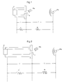
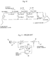
- Fig. 11 is a block schematic diagram.
- a microphone 51 in the arrangement of Fig. 11 converts a vocal sound to an electric signal and outputs a voice signal.
- This voice signal is supplied to a high-pass filter 58 and a low-pass filter 59 via a preamplifier circuit 52, respectively.
- the high-pass filter 58 is designed so as to pass signals at a frequency of 150 Hz or higher.
- the low-pass filter 59 is designed so as to pass low frequency signals containing a main factor of wind noise at a frequency of 150 Hz or lower.
- An output signal of the high-pass filter 58 is supplied to an input terminal of an adder circuit 61.
- An output signal of the low-pass filter 59 is supplied to another input terminal of the adder circuit 61 via an automatic level control circuit 60.
- the automatic level control circuit 60 supplies the output signal of the low-pass filter 59 to the input side of a variable gain amplifier circuit 60a, and results in the variable gain amplifier circuit 60a supplying its output signal to another input terminal of the adder circuit 61.
- the automatic level control circuit 60 supplies the output signal of the variable gain amplifier circuit 60a to a level detection circuit 60b, and reduces the gain of the variable gain amplifier circuit 60a in accordance with a detection level determined by the level detection circuit 60b.
- the automatic level control circuit 60 is designed so as to have no attenuation in the absence of wind noise and an increase in the level of attenuation as the wind noises level increases.
- the first example of the prior art has some problems such as a complex electric circuit construction and an unnatural feeling whilst talking caused by the alteration of the speaker's voice quality due to an alteration in the frequency response when the wind noise prevention function is ON.
- Fig. 12 shows a side view of a handset partly broken away.
- Fig. 13 represents a fragmentary view taken in the direction of an arrow in Fig. 12.
- a protuberant telephone mouthpiece surface 76 has a dome-like shape with its top positioned at the centre of a telephone mouth-piece unit 73 connected to a base 72.
- An acoustic perforation 721 is formed slightly apart from the top of the dome-like shaped telephone mouthpiece surface 786 in the direction opposite to a receiver unit 74.
- the acoustic perforation 721 is so formed as to be apart from the receiver unit 74 as it goes from a front air chamber 78 towards the telephone mouthpiece surface 76.
- the user When speaking using the above hand-set 71, the user usually has his/her ear tightly pressed to the receiver unit 74 for catching the other speaker's voice through an electrodynamic receiver 75.
- the cheek of the speaker is in close contact with the surface of the base 72.
- the user's lips are also located too close to the side of the protuberant domed-shaped telephone mouthpiece unit 73 in the direction of the receiver unit 74.
- the opening section of the acoustic perforation 721 located apart from the top of the telephone mouthpiece surface 76 in the direction towards the receiver unit 74.
- the acoustic perforation 721 is so formed as to be apart from the receiver unit 74 as is the front air chamber 78 apart from the telephone mouthpiece surface 76.
- This construction serves to minimise the possibility of wind entering into the acoustic perforation 721 directly, thus suppressing turbulence occurring therein and reducing noise. Since the space between the speaker's lips and the acoustic perforation 721 is remarkably small, the vocal sound itself becomes almost non-directional, resulting in little degradation in the voice signal.
- the first prior proposed arrangement requires no additional parts or major design modification, reducing the wind noise at a minimum cost.
- the second prior example reduces the effect of the breathing noises of the talker.
- its ability to suppress noise due to turbulence from outside is hardly improved, because it is arranged to cope with the air flow in a certain direction only.
- wind noise may be reduced, even out of doors, and that resonance due to wind noise in the acoustic duct section of a telephone mouthpiece may be reduced.
- a telephone mouthpiece to be described below includes an acoustic duct box provided with an acoustic perforation, a microphone unit provided on a surface of the acoustic duct box facing to another surface of the acoustic duct box having the acoustic perforation, a plurality of partitions provided within the acoustic duct box, and a plurality of slits respectively provided in the partitions.
- P A is an acoustic pressure caused by a speaker
- P B is an acoustic pressure caused by wind noises at an acoustic perforation 1.
- L is a distance where a voice of the speaker passes until reaching to the acoustic perforation 1
- R is an acoustic resistance.
- 1 and 1' are acoustic duct distances between the acoustic perforation 1 and a microphone unit 2, respectively
- r and r' are resistances of distance 1 and distance 1', respectively.
- L is in centimetres and 1 is in millimetres, so the relation between R and r is R>r.
- Attenuation ratios of the generated acoustic pressure P A and the wind noise pressure P B are compared in the cases in which the acoustic duct distances are 1 and 1'.
- the generated acoustic pressure P A is reduced 20% than the case that the acoustic duct distance is 1.
- the wind noise acoustic pressure P B is reduced 50% compared to the case in which the acoustic duct distance is 1.
- the acoustic duct is partitioned by slit partitions.
- air chambers formed by the partitions serve to increase the attenuation of the wind noise acoustic pressure to the microphone greater than that of the generated acoustic pressure of a speaker.
- the present invention enables the effect of wind noise to be reduced without causing a deterioration in the sound quality of a speaker.
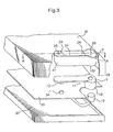
- Fig. 3 is an exploded view showing a part of a hand held portable phone mounted in conjunction with an embodiment of the present invention
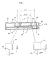
- Fig. 4 is a cross section view on A-A in Fig. 3
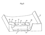
- Fig. 5 is a view showing a reversed upper enclosure of the hand held portable phone of Fig. 3.
- the telephone mouthpiece includes a unit housing section 1, an acoustic duct section 2 which is tightly fitted thereto and which has been integrally formed with an upper enclosure 31 of the hand held portable phone and a microphone unit 3 connected to an electronic circuit base 33 within the hand held portable phone.
- the unit housing section 1 formed of a rubber member has a cylindrical housing 12 for housing the microphone unit 3 at one end of a flat plate 11.
- a protrusion 13 is provided at the other end of the flat plate 11 to be positioned and fixed into a hole 34 formed in the electronic circuit base 33.
- the reason for forming the unit housing section 1 of a rubber member is to increase air tightness with the acoustic duct section 2 and to prevent a leak of the sound.
- the acoustic duct section 2 includes an acoustic duct box 21 in the form of a box in close contact with the corresponding flat plate 11, and a cylindrical box 22 in close contact with the cylindrical housing 12 at an end of the acoustic duct box 21.
- the acoustic duct box 21 includes an acoustic perforation 25 at the other end of the acoustic duct box 21 and on a surface opposite to the surface facing the flat plate 11, and partitions 23 and 24 for partitioning the inside of the acoustic duct box 21 into two air chambers 26 and 27.
- the partitions 23 and 24 are provided with slots or slits 29 and 30, respectively.
- the unit housing section 1 and the acoustic duct section 2 forming the telephone mouthpiece of the present embodiment are disposed between the upper enclosure 31 and a lower enclosure 32.
- the length of the acoustic duct is 15mm
- the distance between the partitions 23 and 24 is 10mm
- the length of a side of a slot or slit 29 is 1.0 mm
- the length of one side of the slot or slit 30 is 0.25 mm.
- Fig. 6 shows comparison data of wind noises of the embodiment constructed as above and illustrating the invention and a conventional telephone mouthpiece which does not have a substantial acoustic duct, but which has a microphone closely touching an acoustic perforation.
- the telephone mouthpiece of the present embodiment acts to reduce wind noise more than the conventional telephone mouthpiece.
- Fig. 7 shows an acoustic duct model employing primary resonance
- Fig. 8 shows an equivalent circuit of the acoustic duct model of Fig. 7.
- D is the diameter of an acoustic perforation
- t is the thickness of a wall of an acoustically perforated section
- V is the volume of an acoustic duct.
- D 0.8 mm
- t 0.8 mm
- V 130 mm3.
- an acoustic perforation (slit or slot) can be substituted by a coil L and a resistor R1.
- a volume, a length of an acoustic duct and a microphone can be substituted by a capacitor C, a resistor R0 and a resistor R2, respectively.
- the units are in mm, 344000 is the speed of sound, ⁇ 0 is the angular speed at the point of resonance, and Q represents the sharpness of the resonance.
- R 1 0.1 ⁇
- L 2(0.8 + 0.15 ⁇ 0.8)/344000 ⁇ 0.8 2 ⁇ 3.14 ⁇ 4.0[H].
- D is calculated by substituting the area of a circular slot or slit by an equivalent area.
- D of the slot or slit 29 of the present arrangement is 1.1 mm approximately, and D for the slot or slit 30 is 0.28 mm approximately.
- R ⁇ t/s is known.
- s is an area of a cross section of the acoustic perforation (slot or slit).
- Fig. 10 an equivalent circuit of the present arrangement can be calculated, resulting in the circuit of Fig. 10.
- the acoustic perforation 25 is replaced by a series circuit of a coil L1 and a resistor R1.
- a slit 29 is replaced by a series circuit of a coil L2 and a resistor R2.
- a slit 30 is replaced by a series circuit of a coil L3 and a resistor R3.
- Air chambers 26, 27 and 28 are replaced by capacitors C1, C2 and C3, respectively.
- the microphone unit 3 is replaced by a resistor R4.
- the length of the acoustic duct is substituted by R0.
- the acoustic duct section 2 as a whole is equivalent to a multi-staged low pass filter.
- Simulation based on the equivalent circuit shown in Fig. 7 enables the values to be varied of the distance between the partition 23 and the partition 24 (the positions of air chambers 26, 27 and 28), and of the sizes of the slots or slits 29 and 30 to values other than those of the particular arrangement described.
Abstract
Description
- This invention relates to a telephone mouthpiece and a method for minimising wind noise, particularly, but not exclusively, for use with a telephone.
- A conventional telephone mouthpiece will be described below with reference to the accompanying drawings.
- A first example of the prior art, which has been disclosed in Japanese Patent Laid-Open No. 214400 (1990), will be described with reference to Fig. 11 which is a block schematic diagram.
- A
microphone 51 in the arrangement of Fig. 11 converts a vocal sound to an electric signal and outputs a voice signal. This voice signal is supplied to a high-pass filter 58 and a low-pass filter 59 via a preamplifier circuit 52, respectively. - The high-
pass filter 58 is designed so as to pass signals at a frequency of 150 Hz or higher. The low-pass filter 59 is designed so as to pass low frequency signals containing a main factor of wind noise at a frequency of 150 Hz or lower. - An output signal of the high-
pass filter 58 is supplied to an input terminal of anadder circuit 61. - An output signal of the low-
pass filter 59 is supplied to another input terminal of theadder circuit 61 via an automaticlevel control circuit 60. At this time, the automaticlevel control circuit 60 supplies the output signal of the low-pass filter 59 to the input side of a variablegain amplifier circuit 60a, and results in the variablegain amplifier circuit 60a supplying its output signal to another input terminal of theadder circuit 61. Simultaneously, the automaticlevel control circuit 60 supplies the output signal of the variablegain amplifier circuit 60a to alevel detection circuit 60b, and reduces the gain of the variablegain amplifier circuit 60a in accordance with a detection level determined by thelevel detection circuit 60b. Namely, the automaticlevel control circuit 60 is designed so as to have no attenuation in the absence of wind noise and an increase in the level of attenuation as the wind noises level increases. - However, the first example of the prior art has some problems such as a complex electric circuit construction and an unnatural feeling whilst talking caused by the alteration of the speaker's voice quality due to an alteration in the frequency response when the wind noise prevention function is ON.
- Next, a second example of the prior art will be explained. The second example of the prior art has been disclosed in Japanese Utility Model Application Laid-Open No. 139649 (1989).
- The second example is shown in Figs. 12 and 13 of the drawings.
- Fig. 12 shows a side view of a handset partly broken away. Fig. 13 represents a fragmentary view taken in the direction of an arrow in Fig. 12.
- Referring to Fig. 12 and Fig. 13, a protuberant
telephone mouthpiece surface 76 has a dome-like shape with its top positioned at the centre of a telephone mouth-piece unit 73 connected to abase 72. Anacoustic perforation 721 is formed slightly apart from the top of the dome-like shaped telephone mouthpiece surface 786 in the direction opposite to areceiver unit 74. Theacoustic perforation 721 is so formed as to be apart from thereceiver unit 74 as it goes from a front air chamber 78 towards thetelephone mouthpiece surface 76. - When speaking using the above hand-set 71, the user usually has his/her ear tightly pressed to the
receiver unit 74 for catching the other speaker's voice through anelectrodynamic receiver 75. The cheek of the speaker is in close contact with the surface of thebase 72. The user's lips are also located too close to the side of the protuberant domed-shapedtelephone mouthpiece unit 73 in the direction of thereceiver unit 74. - When the user speaks in this situation, his/her breathing is directed to the
telephone mouthpiece unit 73, so that the breathing, which is a form of wind, is caused to flow directly to the section of the telephone mouth-piece surface 76 in the direction of thereceiver unit 74, as an arrow A shows. - The opening section of the
acoustic perforation 721 located apart from the top of thetelephone mouthpiece surface 76 in the direction towards thereceiver unit 74. Theacoustic perforation 721 is so formed as to be apart from thereceiver unit 74 as is the front air chamber 78 apart from thetelephone mouthpiece surface 76. - This construction serves to minimise the possibility of wind entering into the
acoustic perforation 721 directly, thus suppressing turbulence occurring therein and reducing noise. Since the space between the speaker's lips and theacoustic perforation 721 is remarkably small, the vocal sound itself becomes almost non-directional, resulting in little degradation in the voice signal. The first prior proposed arrangement requires no additional parts or major design modification, reducing the wind noise at a minimum cost. - The second prior example, reduces the effect of the breathing noises of the talker. When using it outdoors, however, its ability to suppress noise due to turbulence from outside is hardly improved, because it is arranged to cope with the air flow in a certain direction only.
- Features of arrangements to be described below, as examples, are that wind noise may be reduced, even out of doors, and that resonance due to wind noise in the acoustic duct section of a telephone mouthpiece may be reduced.
- A telephone mouthpiece to be described below, as an example, includes an acoustic duct box provided with an acoustic perforation, a microphone unit provided on a surface of the acoustic duct box facing to another surface of the acoustic duct box having the acoustic perforation, a plurality of partitions provided within the acoustic duct box, and a plurality of slits respectively provided in the partitions.
- The principle of the present invention will now be explained. In Fig. 1 and Fig. 2, PA is an acoustic pressure caused by a speaker, PB is an acoustic pressure caused by wind noises at an
acoustic perforation 1. L is a distance where a voice of the speaker passes until reaching to theacoustic perforation 1, R is an acoustic resistance. 1 and 1' are acoustic duct distances between theacoustic perforation 1 and amicrophone unit 2, respectively, r and r' are resistances ofdistance 1 and distance 1', respectively. In a general hand held portable phone, L is in centimetres and 1 is in millimetres, so the relation between R and r is R>r. Here, supposing that the length of the acoustic duct is 1' that is longer than 1 as shown in the figures, the relation between them is r'>r. As a result, the relation between the acoustic resistances is R>r'>r. While, generally, L>1' due to limitations when mounting the microphone in a hand-held-portable phone. - Next, attenuation ratios of the generated acoustic pressure PA and the wind noise pressure PB are compared in the cases in which the acoustic duct distances are 1 and 1'. To simplify the explanation, a condition that r=1, r'=2, R=3 and each acoustic resistance represents its sound source is supposed.
- In this case, the attenuation ratio A of the generated acoustic pressure PA is:

- Like this, in the case in which the acoustic duct distance is 1', the generated acoustic pressure PA is reduced 20% than the case that the acoustic duct distance is 1.
- On the other hand, the attenuation ratio B of the wind noise acoustic pressure PB is:

- Like this, in the case in which the acoustic duct distance is 1', the wind noise acoustic pressure PB is reduced 50% compared to the case in which the acoustic duct distance is 1.
- This means that the longer the acoustic duct distance is set, the more the wind noise acoustic pressure PB is reduced than the generated acoustic pressure PA. Namely, setting the acoustic duct distance longer reduces wind noises more effectively.
- However, setting the acoustic duct distance long only causes a resonance phenomenon due to the frequency response of wind noises.
- To prevent this resonance phenomenon of wind noises, the acoustic duct is partitioned by slit partitions.
- More, air chambers formed by the partitions serve to increase the attenuation of the wind noise acoustic pressure to the microphone greater than that of the generated acoustic pressure of a speaker.
- As a result, the present invention enables the effect of wind noise to be reduced without causing a deterioration in the sound quality of a speaker.
- The following description and drawings disclose, by means of an illustrative example, the invention which is defined in the appended claims, whose scope determines the extent of the protection sought.
- In the drawings:-
- Fig. 1 is a diagram for use in explaining the principle of the present invention,
- Fig. 2 is also a diagram for use in explaining the principle of the present invention,
- Fig. 3 is an exploded perspective view showing diagrammatically a part of a hand held portable phone mounted to employ one embodiment of the present invention,
- Fig. 4 is a cross sectional view on the line A-A in Fig. 3,
- Fig. 5 is a view showing the upper enclosure of the hand held portable phone of Fig. 3 reversed,
- Fig. 6 are graphs enabling data obtained using an embodiment of the invention and of the prior art to be compared,
- Fig. 7 illustrates diagrammatically an acoustic duct model in which primary resonance occurs,
- Fig. 8 shows an equivalent circuit of the acoustic duct model of Fig. 7,
- Fig. 9 shows the frequency response of the acoustic duct model of Fig. 7, and
- Fig. 10 is a diagram showing an equivalent circuit of the presently preferred embodiment.
- An arrangement illustrating an embodiment of the present invention will now be described.
- Fig. 3 is an exploded view showing a part of a hand held portable phone mounted in conjunction with an embodiment of the present invention, Fig. 4 is a cross section view on A-A in Fig. 3 and Fig. 5 is a view showing a reversed upper enclosure of the hand held portable phone of Fig. 3.
- In the embodiment of Figs. 3, 4 and 5, the telephone mouthpiece includes a
unit housing section 1, anacoustic duct section 2 which is tightly fitted thereto and which has been integrally formed with anupper enclosure 31 of the hand held portable phone and amicrophone unit 3 connected to anelectronic circuit base 33 within the hand held portable phone. - The
unit housing section 1 formed of a rubber member has acylindrical housing 12 for housing themicrophone unit 3 at one end of aflat plate 11. Aprotrusion 13 is provided at the other end of theflat plate 11 to be positioned and fixed into ahole 34 formed in theelectronic circuit base 33. The reason for forming theunit housing section 1 of a rubber member is to increase air tightness with theacoustic duct section 2 and to prevent a leak of the sound. - The
acoustic duct section 2 includes anacoustic duct box 21 in the form of a box in close contact with the correspondingflat plate 11, and acylindrical box 22 in close contact with thecylindrical housing 12 at an end of theacoustic duct box 21. Theacoustic duct box 21 includes anacoustic perforation 25 at the other end of theacoustic duct box 21 and on a surface opposite to the surface facing theflat plate 11, andpartitions acoustic duct box 21 into twoair chambers partitions slits - The
unit housing section 1 and theacoustic duct section 2 forming the telephone mouthpiece of the present embodiment are disposed between theupper enclosure 31 and alower enclosure 32. - In the present arrangement, as shown in Fig. 4, it is supposed that the length of the acoustic duct is 15mm, the distance between the
partitions - Fig. 6 shows comparison data of wind noises of the embodiment constructed as above and illustrating the invention and a conventional telephone mouthpiece which does not have a substantial acoustic duct, but which has a microphone closely touching an acoustic perforation.
- As Fig. 6 shows, the telephone mouthpiece of the present embodiment acts to reduce wind noise more than the conventional telephone mouthpiece.
- Next, an equivalent circuit of the illustrative embodiment will be explained.
- To simplify the explanation, an experimental result of a primary resonance circuit will be explained first.
- Fig. 7 shows an acoustic duct model employing primary resonance, and Fig. 8 shows an equivalent circuit of the acoustic duct model of Fig. 7.
- In Fig. 7, D is the diameter of an acoustic perforation, t is the thickness of a wall of an acoustically perforated section and V is the volume of an acoustic duct. In the particular example, D=0.8 mm, t=0.8 mm and V=130 mm³.
- When substituting an acoustic model by an equivalent circuit, an acoustic perforation (slit or slot) can be substituted by a coil L and a resistor R₁. Also, a volume, a length of an acoustic duct and a microphone can be substituted by a capacitor C, a resistor R₀ and a resistor R₂, respectively.
- It is known that each value of a circular acoustic perforation is given by the following equation.


- Where, the units are in mm, 344000 is the speed of sound, ω₀ is the angular speed at the point of resonance, and Q represents the sharpness of the resonance.
- The frequency response of the acoustic duct model is shown in Fig. 9.
- From the frequency response of Fig. 9, the following relations are derived.


- From a real measurement, R₀=0.4Ω and R₂=0.006Ω.
- Therefore,


- Next, each value of the equivalent circuit of the present invention is calculated.
- When the slot or slit is a square, as in the arrangement being described, D is calculated by substituting the area of a circular slot or slit by an equivalent area. As a result, D of the slot or slit 29 of the present arrangement is 1.1 mm approximately, and D for the slot or slit 30 is 0.28 mm approximately.
- In addition, R∝t/s is known. Where, s is an area of a cross section of the acoustic perforation (slot or slit).
- Similarly to the above, an equivalent circuit of the present arrangement can be calculated, resulting in the circuit of Fig. 10. In Fig. 10, the
acoustic perforation 25 is replaced by a series circuit of a coil L₁ and a resistor R₁. Aslit 29 is replaced by a series circuit of a coil L₂ and a resistor R₂. Aslit 30 is replaced by a series circuit of a coil L₃ and a resistor R₃.Air chambers microphone unit 3 is replaced by a resistor R₄. The length of the acoustic duct is substituted by R₀. Theacoustic duct section 2 as a whole is equivalent to a multi-staged low pass filter. - Simulation based on the equivalent circuit shown in Fig. 7 enables the values to be varied of the distance between the
partition 23 and the partition 24 (the positions ofair chambers slits - It will be understood that, although embodiments of the invention have been described, by way of example, with reference to the accompanying drawings, variations and modifications thereof, as well as other embodiments, may be made within the scope of the appended claims.
Claims (20)
- A telephone mouthpiece for minimising wind noise including an acoustic duct box provided with an acoustic perforation, a microphone unit provided on a surface of the acoustic duct box facing towards another surface of the acoustic duct box having the acoustic perforation, a plurality of partitions provided within the acoustic duct box, and a plurality of slots or slits provided in the partitions.
- The telephone mouthpiece of claim 1, wherein the partitions are perpendicular to a surface on which the acoustic perforation is provided and a surface on which the microphone is provided.
- The telephone mouthpiece of claim 1, wherein the partitions are parallel to the surface on which the acoustic perforation is provided and the surface on which the microphone is provided.
- The telephone mouthpiece of claim 1, having slots or slits of different sizes.
- The telephone mouthpiece of claim 1, wherein the acoustic duct box is a part of the telephone mouthpiece enclosure, and the acoustic duct box and the partitions are integrated in a body.
- A telephone mouthpiece including a microphone unit, a unit housing section having a flat plate on one side of which a hole is provided, and a housing section for housing the microphone on the side on which the hole is provided and an acoustic section having an acoustic duct box fitted to the flat plate and provided with an acoustic perforation on a side of a surface of the acoustic duct box facing a surface of the flat plate so that the acoustic perforation does not directly face towards the hole on the flat plate, a plurality of partitions provided within the acoustic duct box, and a plurality of slots or slits in the partitions.
- The telephone mouthpiece of claim 6, wherein the acoustic duct section is integrated in a body with the telephone mouthpiece enclosure and the unit housing section has a protuberance section for positioning in the body of the telephone mouthpiece.
- The telephone mouthpiece of claim 6, wherein the unit housing section is formed of a rubber member.
- The telephone mouthpiece of claim 6, having slots or slits of different sizes.
- The telephone mouthpiece of claim 6, wherein the partitions are provided perpendicular to a surface on which the acoustic perforation is provided and a surface on which the unit housing section is provided.
- The telephone mouth piece of claim 10, wherein a first partition and a second partition are provided in order from the acoustic perforation, the distance between the first partition and the second partition is about 10 mm, a square slot or slit, of which each side is about 1 mm, is provided in the first partition and a square slot or slit of which each side is about 0.25 mm is provided in said second partition.
- A telephone mouthpiece including a microphone unit, a unit housing section having a flat plate, a hole provided on a side of the flat plate, and a cylindrical box for housing the microphone unit on the side where the hole is provided, and an acoustic duct section having an acoustic duct box fitted to the flat plate of the unit housing section and provided with an acoustic perforation on a surface opposite to the side of the flat plate where the hole is provided, a plurality of partitions within the acoustic duct box, and a plurality of slots or slits in the partitions.
- The telephone mouthpiece of claim 12, having slots or slits of different sizes.
- The telephone mouthpiece of claim 12, wherein the unit housing section is a rubber member.
- The telephone mouthpiece of claim 12, wherein the acoustic duct section is integrated in a body with the telephone mouthpiece enclosure and the unit housing section has a protuberance section for positioning in the body in the telephone mouthpiece.
- The telephone mouthpiece of claim 6, wherein the unit housing section is a rubber member.
- The telephone mouthpiece of claim 12, wherein the partitions are provided perpendicular to a surface on which the acoustic perforation is provided and a surface on which the unit housing section is provided.
- The telephone mouthpiece of claim 17, wherein a first partition is provided on the acoustic perforation side of the acoustic duct box and a second partition is provided on a microphone unit side of the acoustic duct box, and the distance between the first partition and the second partition is about 10 mm, a square slot or slit of which each side is about 1 mm is provided on the first partition and a square slot or slit of which each side is about 0.25 mm is provided on the second partition.
- A method for minimising wind noise input to a telephone mouthpiece including the step of partitioning an acoustic duct connecting an acoustic perforation into which sound is input and a microphone unit that converts the sound to an electric signal, a plurality of partitions in which there is a plurality of slots or slits being provided.
- The method of claim 19, having slots or slits of different sizes.
Applications Claiming Priority (3)
| Application Number | Priority Date | Filing Date | Title |
|---|---|---|---|
| JP246109/94 | 1994-10-12 | ||
| JP24610994 | 1994-10-12 | ||
| JP6246109A JP2609822B2 (en) | 1994-10-12 | 1994-10-12 | Transmitter |
Publications (3)
| Publication Number | Publication Date |
|---|---|
| EP0707403A2 true EP0707403A2 (en) | 1996-04-17 |
| EP0707403A3 EP0707403A3 (en) | 1998-03-18 |
| EP0707403B1 EP0707403B1 (en) | 2004-09-22 |
Family
ID=17143623
Family Applications (1)
| Application Number | Title | Priority Date | Filing Date |
|---|---|---|---|
| EP95307149A Expired - Lifetime EP0707403B1 (en) | 1994-10-12 | 1995-10-10 | Telephone mouthpiece and method for minimising wind noise |
Country Status (4)
| Country | Link |
|---|---|
| US (1) | US5701354A (en) |
| EP (1) | EP0707403B1 (en) |
| JP (1) | JP2609822B2 (en) |
| AU (1) | AU708292B2 (en) |
Cited By (5)
| Publication number | Priority date | Publication date | Assignee | Title |
|---|---|---|---|---|
| WO1997042745A1 (en) * | 1996-05-03 | 1997-11-13 | Telefonaktiebolaget Lm Ericsson (Publ) | Michrophone in a speech communicator |
| GB2315633A (en) * | 1996-07-19 | 1998-02-04 | Nec Corp | Acoustic resistance cloth filling channel between microphone and off-set sound port improves wind screening |
| EP1780989A1 (en) * | 2005-10-26 | 2007-05-02 | Research In Motion Limited | Microphone coupler for a communication device |
| US7555118B2 (en) | 2005-10-26 | 2009-06-30 | Research In Motion Limited | Microphone coupler for a communication device |
| CN101742371A (en) * | 2008-11-12 | 2010-06-16 | 潍坊歌尔电子有限公司 | Microphone capable of suppressing wind noise |
Families Citing this family (20)
| Publication number | Priority date | Publication date | Assignee | Title |
|---|---|---|---|---|
| US5890072A (en) * | 1996-11-07 | 1999-03-30 | Ericsson, Inc. | Radiotelephone having a non-resonant wave guide acoustically coupled to a microphone |
| US6038328A (en) * | 1997-07-07 | 2000-03-14 | Hughes Electronics Corporation | Minimization of acoustic echo effects in a microphone boot |
| US6101402A (en) * | 1997-09-04 | 2000-08-08 | Ericcson Inc. | Radiotelephone with sliding acoustic member |
| GB2333004B (en) | 1997-12-31 | 2002-03-27 | Nokia Mobile Phones Ltd | Earpiece acoustics |
| JP4000217B2 (en) * | 1998-05-15 | 2007-10-31 | 株式会社オーディオテクニカ | Microphone |
| JP4258225B2 (en) * | 2003-02-14 | 2009-04-30 | トヨタ自動車株式会社 | Vehicle position detection apparatus and method |
| US20060147060A1 (en) * | 2004-12-30 | 2006-07-06 | Plantronics, Inc. A Delaware Corporation | Multifunction preamplifier microphone |
| US20080159558A1 (en) * | 2006-12-28 | 2008-07-03 | Fortemedia, Inc. | Internal microphone array or microphone module not affecting appearance of electronic device |
| US8306252B2 (en) * | 2007-01-05 | 2012-11-06 | Apple Inc. | Integrated microphone assembly for personal media device |
| US8126138B2 (en) | 2007-01-05 | 2012-02-28 | Apple Inc. | Integrated speaker assembly for personal media device |
| JP4762927B2 (en) * | 2007-02-01 | 2011-08-31 | 富士通株式会社 | Electronic device, method for manufacturing electronic device, and portable terminal device |
| JP4924074B2 (en) * | 2007-02-09 | 2012-04-25 | 日本電気株式会社 | Microphone mounting structure in electronic equipment and electronic equipment |
| US8351633B2 (en) * | 2008-09-17 | 2013-01-08 | Teodoro Lassally | Noise cancelling microphone with wind shield |
| WO2010068961A1 (en) * | 2008-12-15 | 2010-06-24 | Blueant Wireless Pty Limited | An audio device |
| US8290546B2 (en) | 2009-02-23 | 2012-10-16 | Apple Inc. | Audio jack with included microphone |
| EP2556681B1 (en) * | 2010-04-06 | 2018-02-21 | Widex A/S | Hearing aid adapted for suppression of wind noise |
| WO2020051786A1 (en) * | 2018-09-12 | 2020-03-19 | Shenzhen Voxtech Co., Ltd. | Signal processing device having multiple acoustic-electric transducers |
| US9066172B2 (en) | 2012-09-28 | 2015-06-23 | Apple Inc. | Acoustic waveguide and computing devices using same |
| US9380369B2 (en) | 2013-02-14 | 2016-06-28 | Apple Inc. | Microphone seal |
| CN216599960U (en) * | 2021-09-27 | 2022-05-24 | 北京罗克维尔斯科技有限公司 | Vehicle-mounted microphone and vehicle |
Citations (2)
| Publication number | Priority date | Publication date | Assignee | Title |
|---|---|---|---|---|
| JPH01139649A (en) | 1987-11-27 | 1989-06-01 | Toshiba Corp | Composition for mold cleaning |
| JPH02214400A (en) | 1989-02-15 | 1990-08-27 | Sony Corp | Microphone device |
Family Cites Families (16)
| Publication number | Priority date | Publication date | Assignee | Title |
|---|---|---|---|---|
| US1419606A (en) * | 1922-01-27 | 1922-06-13 | Jack Dietrich | Telephone muffler |
| GB732243A (en) * | 1952-09-10 | 1955-06-22 | Isaac Levin | Improvements in or relating to telephone mouthpieces |
| US3553374A (en) * | 1969-03-20 | 1971-01-05 | Digitronics Corp | Acoustic coupler |
| US3796842A (en) * | 1972-07-20 | 1974-03-12 | E Guille | Dictation mask |
| JPS6017191B2 (en) * | 1977-12-30 | 1985-05-01 | アイホン株式会社 | Microphone unit with wind noise attenuation effect |
| ATA74486A (en) * | 1986-03-20 | 1987-04-15 | Akg Akustische Kino Geraete | DIRECTIONAL MICROPHONE ACCORDING TO THE ELECTROSTATIC OR ELECTRODYNAMIC CONVERTER PRINCIPLE |
| JPH0727715Y2 (en) * | 1989-02-06 | 1995-06-21 | 株式会社東芝 | Handset |
| US5239578A (en) * | 1990-05-15 | 1993-08-24 | Plantronics, Inc. | Noise cancelling apparatus for a telephone handset |
| US5282245A (en) * | 1990-08-13 | 1994-01-25 | Shure Brothers, Incorporated | Tubular bi-directional microphone with flared entries |
| DE69232313T2 (en) * | 1992-05-11 | 2002-06-20 | Jabra Corp | UNIDIRECTIONAL EARPHONE AND METHOD THEREFOR |
| US5288955A (en) * | 1992-06-05 | 1994-02-22 | Motorola, Inc. | Wind noise and vibration noise reducing microphone |
| US5343523A (en) * | 1992-08-03 | 1994-08-30 | At&T Bell Laboratories | Telephone headset structure for reducing ambient noise |
| TW274675B (en) * | 1992-09-08 | 1996-04-21 | Motorola Inc | |
| CA2101500C (en) * | 1992-09-30 | 1996-12-17 | Charles Spurgeon Bartlett | Noise-cancelling telephone handset |
| US5448637A (en) * | 1992-10-20 | 1995-09-05 | Pan Communications, Inc. | Two-way communications earset |
| JP2626534B2 (en) * | 1993-12-28 | 1997-07-02 | 日本電気株式会社 | Transmission structure of electronic equipment |
-
1994
- 1994-10-12 JP JP6246109A patent/JP2609822B2/en not_active Expired - Fee Related
-
1995
- 1995-10-10 EP EP95307149A patent/EP0707403B1/en not_active Expired - Lifetime
- 1995-10-10 US US08/541,411 patent/US5701354A/en not_active Expired - Lifetime
- 1995-10-11 AU AU33185/95A patent/AU708292B2/en not_active Ceased
Patent Citations (2)
| Publication number | Priority date | Publication date | Assignee | Title |
|---|---|---|---|---|
| JPH01139649A (en) | 1987-11-27 | 1989-06-01 | Toshiba Corp | Composition for mold cleaning |
| JPH02214400A (en) | 1989-02-15 | 1990-08-27 | Sony Corp | Microphone device |
Cited By (11)
| Publication number | Priority date | Publication date | Assignee | Title |
|---|---|---|---|---|
| WO1997042745A1 (en) * | 1996-05-03 | 1997-11-13 | Telefonaktiebolaget Lm Ericsson (Publ) | Michrophone in a speech communicator |
| US5913178A (en) * | 1996-05-03 | 1999-06-15 | Telefonaktiebolaget Lm Ericsson | Microphone in a speech communicator |
| GB2315633A (en) * | 1996-07-19 | 1998-02-04 | Nec Corp | Acoustic resistance cloth filling channel between microphone and off-set sound port improves wind screening |
| US6091830A (en) * | 1996-07-19 | 2000-07-18 | Nec Corporation | Transmitter structure for limiting the effects of wind noise on a microphone |
| GB2315633B (en) * | 1996-07-19 | 2000-12-20 | Nec Corp | Transmitter structure |
| EP1780989A1 (en) * | 2005-10-26 | 2007-05-02 | Research In Motion Limited | Microphone coupler for a communication device |
| US7555118B2 (en) | 2005-10-26 | 2009-06-30 | Research In Motion Limited | Microphone coupler for a communication device |
| EP2244445A1 (en) * | 2005-10-26 | 2010-10-27 | Research In Motion Limited | Electromagnetic shielded audio system for a communication device |
| US8005207B2 (en) | 2005-10-26 | 2011-08-23 | Research In Motion Limited | Microphone coupler system for a communication device |
| US8488777B2 (en) | 2005-10-26 | 2013-07-16 | Research In Motion Limited | Microphone coupler system for a communication device |
| CN101742371A (en) * | 2008-11-12 | 2010-06-16 | 潍坊歌尔电子有限公司 | Microphone capable of suppressing wind noise |
Also Published As
| Publication number | Publication date |
|---|---|
| AU708292B2 (en) | 1999-07-29 |
| AU3318595A (en) | 1996-04-26 |
| JPH08111705A (en) | 1996-04-30 |
| EP0707403A3 (en) | 1998-03-18 |
| EP0707403B1 (en) | 2004-09-22 |
| US5701354A (en) | 1997-12-23 |
| JP2609822B2 (en) | 1997-05-14 |
Similar Documents
| Publication | Publication Date | Title |
|---|---|---|
| EP0707403B1 (en) | Telephone mouthpiece and method for minimising wind noise | |
| US6091830A (en) | Transmitter structure for limiting the effects of wind noise on a microphone | |
| US4160135A (en) | Closed earphone construction | |
| US5282245A (en) | Tubular bi-directional microphone with flared entries | |
| US6321070B1 (en) | Portable electronic device with a speaker assembly | |
| US6785395B1 (en) | Speaker configuration for a portable electronic device | |
| US5473684A (en) | Noise-canceling differential microphone assembly | |
| US6134336A (en) | Integrated speaker assembly of a portable electronic device | |
| US5896461A (en) | Compact speakerphone apparatus | |
| US6058315A (en) | Speaker assembly for a radiotelephone | |
| CN112637736B (en) | Earphone system and microphone device thereof | |
| US6272360B1 (en) | Remotely installed transmitter and a hands-free two-way voice terminal device using same | |
| EP3021560B1 (en) | Speaker back cavity | |
| EP0364935B1 (en) | Telephone transducer | |
| US7260236B2 (en) | Wind noise suppression in directional microphones | |
| JP2859527B2 (en) | Loudspeaker assembly | |
| EP0661902A1 (en) | Noise removing apparatus in a microphone | |
| GB2064265A (en) | Microphone unit | |
| CN112437379A (en) | In-ear earphone | |
| EP1074168B1 (en) | Telephone with means for anhancing the low-frequency response | |
| JP2590651B2 (en) | Microphone unit mounting structure | |
| CN112929774A (en) | Capacitor microphone core with shunt channel | |
| CN102918871A (en) | Hearing aid adapted for suppression of wind noise | |
| JP2548062Y2 (en) | Transmitter structure | |
| EP0469955A2 (en) | Transmitter-receiver handset |
Legal Events
| Date | Code | Title | Description |
|---|---|---|---|
| PUAI | Public reference made under article 153(3) epc to a published international application that has entered the european phase |
Free format text: ORIGINAL CODE: 0009012 |
|
| AK | Designated contracting states |
Kind code of ref document: A2 Designated state(s): GB IT |
|
| PUAL | Search report despatched |
Free format text: ORIGINAL CODE: 0009013 |
|
| AK | Designated contracting states |
Kind code of ref document: A3 Designated state(s): GB IT |
|
| 17P | Request for examination filed |
Effective date: 19980218 |
|
| 17Q | First examination report despatched |
Effective date: 20020716 |
|
| GRAP | Despatch of communication of intention to grant a patent |
Free format text: ORIGINAL CODE: EPIDOSNIGR1 |
|
| GRAS | Grant fee paid |
Free format text: ORIGINAL CODE: EPIDOSNIGR3 |
|
| GRAA | (expected) grant |
Free format text: ORIGINAL CODE: 0009210 |
|
| AK | Designated contracting states |
Kind code of ref document: B1 Designated state(s): GB IT |
|
| REG | Reference to a national code |
Ref country code: GB Ref legal event code: FG4D |
|
| PLBE | No opposition filed within time limit |
Free format text: ORIGINAL CODE: 0009261 |
|
| STAA | Information on the status of an ep patent application or granted ep patent |
Free format text: STATUS: NO OPPOSITION FILED WITHIN TIME LIMIT |
|
| 26N | No opposition filed |
Effective date: 20050623 |
|
| PGFP | Annual fee paid to national office [announced via postgrant information from national office to epo] |
Ref country code: IT Payment date: 20091016 Year of fee payment: 15 Ref country code: GB Payment date: 20091007 Year of fee payment: 15 |
|
| GBPC | Gb: european patent ceased through non-payment of renewal fee |
Effective date: 20101010 |
|
| PG25 | Lapsed in a contracting state [announced via postgrant information from national office to epo] |
Ref country code: GB Free format text: LAPSE BECAUSE OF NON-PAYMENT OF DUE FEES Effective date: 20101010 |
|
| PG25 | Lapsed in a contracting state [announced via postgrant information from national office to epo] |
Ref country code: IT Free format text: LAPSE BECAUSE OF NON-PAYMENT OF DUE FEES Effective date: 20101010 |