EP0707370A2 - Verfahren und Vorrichtung zur Steuerung einer Anlage zur Übertragung von Hochspannungsgleichstrom - Google Patents
Verfahren und Vorrichtung zur Steuerung einer Anlage zur Übertragung von Hochspannungsgleichstrom Download PDFInfo
- Publication number
- EP0707370A2 EP0707370A2 EP95115863A EP95115863A EP0707370A2 EP 0707370 A2 EP0707370 A2 EP 0707370A2 EP 95115863 A EP95115863 A EP 95115863A EP 95115863 A EP95115863 A EP 95115863A EP 0707370 A2 EP0707370 A2 EP 0707370A2
- Authority
- EP
- European Patent Office
- Prior art keywords
- current
- voltage
- value
- converter
- direct
- Prior art date
- Legal status (The legal status is an assumption and is not a legal conclusion. Google has not performed a legal analysis and makes no representation as to the accuracy of the status listed.)
- Granted
Links
Images


Classifications
-
- H—ELECTRICITY
- H02—GENERATION; CONVERSION OR DISTRIBUTION OF ELECTRIC POWER
- H02J—CIRCUIT ARRANGEMENTS OR SYSTEMS FOR SUPPLYING OR DISTRIBUTING ELECTRIC POWER; SYSTEMS FOR STORING ELECTRIC ENERGY
- H02J3/00—Circuit arrangements for ac mains or ac distribution networks
- H02J3/36—Arrangements for transfer of electric power between ac networks via a high-tension dc link
-
- Y—GENERAL TAGGING OF NEW TECHNOLOGICAL DEVELOPMENTS; GENERAL TAGGING OF CROSS-SECTIONAL TECHNOLOGIES SPANNING OVER SEVERAL SECTIONS OF THE IPC; TECHNICAL SUBJECTS COVERED BY FORMER USPC CROSS-REFERENCE ART COLLECTIONS [XRACs] AND DIGESTS
- Y02—TECHNOLOGIES OR APPLICATIONS FOR MITIGATION OR ADAPTATION AGAINST CLIMATE CHANGE
- Y02E—REDUCTION OF GREENHOUSE GAS [GHG] EMISSIONS, RELATED TO ENERGY GENERATION, TRANSMISSION OR DISTRIBUTION
- Y02E60/00—Enabling technologies; Technologies with a potential or indirect contribution to GHG emissions mitigation
- Y02E60/60—Arrangements for transfer of electric power between AC networks or generators via a high voltage DC link [HVCD]
Definitions
- the present invention relates to a method for control of an installation for transmission of high-voltage direct current according to the precharacterising part of claim 1 and to a device for carrying out the method.
- An installation for transmission of high-voltage direct current between two alternating-voltage networks comprises two converter stations, each one connected on its ac (alternating current) side to a separate one of the alternating-voltage networks, and a common dc (direct current) connection.
- the dc connection may be in the form of an overhead line and/or a cable and also in certain parts consist of ground or water instead of a metallic conductor.
- Each one of the converter stations comprises a converter, usually at least one converter transformer for connection of the converter to the alternating-voltage network, as well as shunt filters for generation of reactive power and filtering of harmonics.
- the converters are normally line-commutated, current-source converters, by which is to be understood that the current commutation between the valves of the converters takes place by means of voltages occurring in the alternating-voltage network, and that the dc connection, viewed from the converters, occurs as a stiff current source.
- one of the converters hereinafter referred to as the rectifier
- the other hereinafter referred to as the inverter
- Control equipment for the respective converter generates a control signal corresponding to a control angle ⁇ at which firing pulses are applied to the valves of the converters.
- the control system of the installation is, therefore, usually designed such that the inverter is controlled to a suitable maximum direct voltage for the operating conditions of the installation, taking into consideration safety margins with respect to commutating errors, voltage variations on the ac network, and other deviations from nominal operation which may occur, whereas the rectifier is controlled in current control.
- the current reference value of the current control is formed in dependence on a current order, which is turn is formed in dependence on a power order and the prevailing direct voltage in such a way that the direct current and hence the transferred active power remain at desired values.
- the control angle of the rectifier during stationary operation is chosen as small as possible while taking into consideration that the current control requires a certain control margin with respect to the smallest permissible control angle which is required for maintaining reliable operation.
- the control equipment for a rectifier and an inverter is designed in similar manner, whereby in the rectifier a current controller is activated and in the inverter control equipment for a control with the aim of maintaining the extinction angle at, but not lower than, a preselected lowest value is activated.
- This is achieved by applying to the current controllers of both the rectifier and the inverter current reference values formed in dependence on the current order for the rectifier and to the current controller of the inverter, in addition, a current margin with a value different from zero and with such a sign that the current controller strives to reduce the direct current controlled by the rectifier.
- the current margin of the rectifier is given a value equal to zero.
- the current orders and the current margins for the rectifier and the inverter are coordinated via a telecommunication link.
- Voltage reductions in the alternating-voltage network of the rectifier may lead to the rectifier not being able to maintain the ordered current.
- the inverter takes over the current control and controls the current on a value equal to the current order reduced by the current margin.
- the transferred active power in the dc connection thus drops in relation to the amounts of the voltage reduction and of the current margin.
- the transition process is usually also associated with a transient reduction of the current by a value greater than the current margin.
- the current margin has usually been given values of typically 0.1 per unit, among other things due to the need of coordination of the current order between the rectifier and the inverter, which has often been performed through ordinary telephone communication. With faster and automatically operating telecommunication links, the current margin may be reduced to typically the order of magnitude of 0.02 per unit. This means that unavoidable transitions of the current control to the inverter are performed with a smaller reduction of the current and with less transients during the transition process.
- the direct voltage at nominal control angle for a series-compensated converter station will have a flatter dependence on the control angle, which entails a reduced control margin.
- the control equipment of the converter normally comprises a limitation of the current order in dependence on the direct voltage at the respective converter, designed such that the current order with decreasing direct voltage is limited to a value decreasing with the voltage and is limited, at a lower voltage level, to a constant value.
- Current controllers in the control equipment of the converters are supplied with the current order, thus limited, as current reference values.
- the current controller of the inverter then tends to increase the current, which can only take place by a further reduction of the direct voltage of the inverter.
- the control equipment of the inverter strives, with respect to the direct voltage of the inverter, in a direction opposite to the direction aimed at with its control, and it is clear that the risk of this situation arising increases with decreasing current margin.
- the invention aims at developing a method of the above-mentioned kind, which permits a low current margin in connection with voltage variations occurring during normal operation and which, in case of large voltage reductions, makes it possible to ensure that the control equipment of the inverter continues to operate in the desired manner, that is, to strive to increase the voltage to a suitable maximum voltage for the operating conditions of the installation.
- Figure 1 shows an installation for transmission of high-voltage direct current between two three-phase alternating-voltage network N1 and N2, only roughly indicated.
- a first converter SR1 is connected with its alternating-voltage terminals to the network N1 via series capacitors SC1 and a transformer T1 and a second converter SR2 is connected with its alternating-voltage terminals to the network N2 via series capacitors SC2 and a transformer T2.
- Each one of the transformers is equipped with a tap-changer TC1, TC2, respectively, marked with an arrow in the figure.
- a dc connection L1, L2 connects the direct-voltage terminals of the converter SR1 to the corresponding direct-voltage terminals on the converter SR2.
- the impedances of the dc connection are designated Z1, Z2, respectively.
- shunt filters (not shown in the figure) for generation of reactive power and filtering of harmonics are connected to the respective alternating-voltage network.
- the direct voltage UD1 of the rectifier and the direct voltage Ud2 of the inverter are measured by means of voltage-measuring devices UM1, UM2, respectively, which deliver the measured values UD1 and UD2, respectively.
- the current Id through the dc connection is measured by means of current measuring devices IM1, IM2, respectively, which deliver the measured values ID1 and ID2, respectively.
- the voltages Un1 and Un2, respectively, of the alternating-voltage network are measured by means of voltage-measuring devices UMN1 and UMN2, respectively, which deliver the measured values UN1 and UN2, respectively.
- Each converter is equipped with a piece of control equipment CE1, CE2, respectively, to which the above-mentioned measured values of the operating parameters of the installation are supplied, that is, the control equipment of the rectifier is supplied with measured values for the voltage of the alternating-voltage network, for the direct voltage of the rectifier, and the direct current in the dc connection, and the control equipment of the inverter is supplied with corresponding measured values relating to the inverter.
- the pieces of control equipment are supplied (in a manner not shown in the drawings but known per se) with input signals with information about the position of the tap changers and a power-direction signal RECT/INV, the latter signal indicating rectifier operation and inverter operation, respectively, and being determined in dependence on the power direction requested by the operator of the installation.
- the pieces of control equipment of the rectifier and the inverter In dependence on measured values and input signals supplied to the pieces of control equipment, the pieces of control equipment of the rectifier and the inverter generate control pulses CP1 and CP2, respectively, for valves arranged in a known manner in the converters and supply these to the respective valve.
- Each one of the pieces of control equipment comprises a control angle unit CAC for forming an ordered value of a control angle ⁇ for the valves of the respective converter, which control angle unit will be described in greater detail below, and units CFC, designed in a known manner, for determining the firing moment of the respective valve in dependence on the ordered value of the control angle ⁇ , and CPG for generating control pulses CP1 and CP2, respectively.
- a reference value, formed in a manner known per se, for the direct current in the dc connection is supplied to the control angle unit CAC from a power control unit POC.
- the control angle unit may also be supplied with other reference values from superordinate control systems, not shown in the figure, for example for control of reactive power exchange with the alternating-voltage networks.
- the two pieces of control equipment communicate with each other, in a manner known per se, via a telecommunication link TL for two-way transmission of information about the operating parameters of the converters.
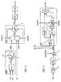
- Figure 2 shows parts of a piece of control equipment for the converter stations according to Figure 1, in one embodiment of the invention.
- the pieces of control equipment are usually designed identically for both rectifiers and inverters, and therefore in the following Figure 2 and the subsequent Figure 3, indices 1 and 2, respectively, for indicating quantities relating to a rectifier and an inverter are not indicated.
- the power control unit POC comprises a calculating member IOCAL for calculating a current order IO as the quotient between a power order PO for transferred active power in the dc connection and a measured value UD of the direct voltage Ud in the rectifier.
- the current order is supplied to a limiting member 1 for limiting the current order in dependence on the measured value UD of the direct voltage Ud, supplied to the above-mentioned limiting member, according to a preselected relationship for the installation.
- the output signal IOL from the limiting member 1 is thereafter supplied to a current controller CC comprised in the control angle unit CAC as current reference value for this controller, whereby the current controller of the rectifier is supplied with a first current reference value IOL1 and the current controller of the inverter is supplied with a second current reference value IOL2.
- the output signal AO of the current controller is limited to its maximum and its minimum value in a limiting member 2 by means of limiting signals AMAXL and AMINL, respectively, which are formed in some manner known per se and are capable of being influenced.
- the output signal AOL from the limiting member 2 forms an ordered value of the control angle ⁇ and is supplied to the unit CFC for determining the firing moment of the respective valve.
- Figure 3 shows an embodiment of the current controller CC.
- a summator 3 forms as output signal the difference between the current reference value IOL for the direct current Id and the measured value ID of this current.
- the difference is supplied to a proportional-amplifying member 4 with a gain GP and to a summator 5.
- the summator 5 is also supplied with a preselected current margin IOM between the rectifier and the inverter, and thus forms as output signal the difference between the current margin and the output signal from the summator 3.
- the output signal from the summator 5 is supplied to an integrating member 6 with the integration time constant 1/GI.
- the integrating member comprises a limiting member 7 which limits the output signal from the integrating member to its maximum and to its minimum value in dependence on the limiting signals AMAXL and AMINL, respectively.
- the output signals from the proportional-amplifying member 4 and the integrating member 6, limited by the limiting member 7, are supplied to a summator 8, which as output signal forms the output signal AO of the current controller as the difference between the output signal from the integrating member and the output signal from the proportional-amplifying member.
- the current orders IO for the rectifier and the inverter are coordinated via the telecommunication link TL ( Figure 1).
- the current margin IOM is set equal to zero for the rectifier, and for the inverter at a value different from zero and with such a sign that the control equipment of the inverter strives to reduce the direct current controlled by the rectifier.
- the input signal to the integrating member 6 consists of the current margin, which means that its output signal will assume its maximum value limited by the limiting signal AMAXL.
- the output signal from the proportional-amplifying member 4 is, under the above-mentioned conditions, equal to zero or near zero, so the value of the control angle ⁇ ordered by the inverter is determined by the above-mentioned limiting signal.
- Figure 4 shows a relationship of a known kind between the measured value UD of the direct voltage Ud at the respective converter and the output signal IOL from the limiting member 1, that is, the current reference value for the current controller of the converter.
- the output signal IOL expressed in per unit
- the measured value UD of the direct voltage also expressed in per unit.
- the points C and C' correspond to a first limiting voltage Udlim1, corresponding to the measured value UDlim1
- the point D corresponds to a second limiting voltage Udlim2, lower than the first and corresponding to the measured value UDlim2.
- the maximum output signal IOL is equal to a lowest value IOLmin to which the current order is limited.
- the point E corresponds to the voltage zero.
- the output signal IOL of the limiting device corresponds to the current order IO supplied to the limiting member.
- the curve B-C-D-E corresponds to a current order equal to 1.0 per unit
- the curve B'-C'-D-E corresponds to a current order equal to 0.5 per unit
- the curve B''-D-E corresponds to a current order equal to 0.3 per unit.
- the first limiting voltage is equal to 0.6 per unit and the second equal to 0.1 per unit and the lowest value IOLmin to which the current order is limited is equal to 0.3 per unit.
- Figure 5 shows a static current/voltage characteristic of a known kind for the installation described with reference to Figure 1.
- the direct voltage for the respective converter expressed in per unit
- the direct current Id in the dc connection also expressed in per unit
- the curve A-B-C-D-E relates to the rectifier, that is, the first converter SR1
- the curve F'-F-G-H-I-K-L relates to the inverter, that is, the second converter SR2.
- F With the current order equal to 1.0 per unit, F becomes the operating point of the installation.
- the current margin IOM for the inverter has the value 0.1 and constitutes in Figure 5 the horizontal distance between the vertical curve parts B-C-D-E and G-H-I-K.
- the curve part F-G for the inverter is given a positive inclination to achieve damping of oscillations around the working point F.
- the curve part B-C-D-E reflects the relationship described above between the direct voltage Ud at the respective converter and the output signal IOL from the limiting member 1.
- the current margin is now formed in dependence on the direct voltage Ud at the respective converter.
- the measured value UD of the direct voltage is supplied to a filter 10 with low-pass characteristic ( Figure 3), the output signal of which is supplied to a function-forming member 11.
- the output signal from the function-forming member 11 is supplied to the selector 9 and forms the current margin IOM when the selector, controlled by the power-direction signal RECT/INV, connects the above-mentioned output signal to the summator 5 in the current controller of the inverter.
- the output signal from the function-forming member 11 is formed in dependence on the measured value UD according to a preselected relationship for the installation, as illustrated in Figure 6.
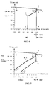
- Figure 6 shows a static current/voltage characteristic of the same kind as that shown in Figure 5, but to clarify the invention Figure 6 does not show the intervention from the limiting member 1.
- a first voltage level Udf corresponding to a point M on the characteristic of the inverter, and up to the voltage level corresponding to the point G
- the current margin assumes a first value IOMf, corresponding to the horizontal distance between the curve parts B-B' and G-M.
- the current margin increases monotonously, in this embodiment linearly, with decreasing voltage to a second value IOMs, corresponding to the horizontal distance between the curve parts B-B' and N-N', and the magnitude of which is larger than the magnitude of the first value.
- the current margin remains constant and equal to the second value IOMs.
- the first voltage level Udf is equal to 0.8 per unit and the second voltage level Uds equal to 0.6 per unit.
- the first value IOMf of the current margin is equal to 0.02 per unit and its second IMOs equal to 0.4 per unit.
- Figure 7 shows a static current/voltage characteristic of the same kind as that shown in Figure 5, with interventions from the limiting member 1 and with a voltage-depending current margin as described with reference to Figure 6.
- the current margin corresponds to the horizontal distance between the curve parts B-C-D-E and F-G-M-H, N-I'.
- the current margin such that its second value is larger in magnitude than the lowest current reference value IOLmin to which the current order IO is limited by the first limiting member 1. Especially when resuming power after a fault in the dc transmission, this ensures that the control equipment of the inverter will strive towards the highest possible direct voltage while the rectifier is building up the direct current, which means that ordered active power is rapidly attained.
- the current margin has been chosen to be a value 0.4 per unit, which is greater in magnitude than the lowest limiting value, equal to 0.3 per unit, to which the limiting member 1 limits the current reference value IOL for the current controller.
- the first voltage level Udf of the function-forming member 11 is higher than the first limiting voltage Udlim1 of the limiting member 1.
- the advantage is achieved that, in case of voltage variations occurring during normal operation, the installation is able to operate with a low current margin, which during unavoidable transitions of the current control to the inverter means that these take place with small disturbances in the operation and low reductions of transferred power, while at the same time, in case of large voltage reductions, typically larger than 0.1 per unit, the control equipment of the inverter continues to operate in the desired way, that is, to strive to increase the voltage to a suitable maximum voltage for the operating conditions of the installation.
- the installation shown in Figure 1 comprises series-compensated converter stations.
- the problem solved by the invention also arises in non-series-compensated converter stations and, consequently, it is applicable to such installations as well.
- the invention is especially important in series-compensated converter stations in which the rectifier operates at low nominal control angles and in which the risk of transition of the current control to the inverter is greater than for non-compensated converter stations.
- the limiting members and function-forming members shown in block diagrams may, in applicable parts, be designed as a model comprising analog and/or digital means for the modelling, or be completely or partially designed as calculations by means of analog and/or digital technique in hard-wired circuits, or be implemented as programs in a microprocessor.
Applications Claiming Priority (3)
| Application Number | Priority Date | Filing Date | Title |
|---|---|---|---|
| SV9403486 | 1994-10-13 | ||
| SE9403486A SE9403486L (sv) | 1994-10-13 | 1994-10-13 | Förfarande och anordning för styrning av en anläggning för överföring av högspänd likström |
| SE9403486 | 1994-10-13 |
Publications (3)
| Publication Number | Publication Date |
|---|---|
| EP0707370A2 true EP0707370A2 (de) | 1996-04-17 |
| EP0707370A3 EP0707370A3 (de) | 1997-05-02 |
| EP0707370B1 EP0707370B1 (de) | 1999-08-18 |
Family
ID=20395596
Family Applications (1)
| Application Number | Title | Priority Date | Filing Date |
|---|---|---|---|
| EP95115863A Expired - Lifetime EP0707370B1 (de) | 1994-10-13 | 1995-10-09 | Verfahren und Vorrichtung zur Steuerung einer Anlage zur Übertragung von Hochspannungsgleichstrom |
Country Status (6)
| Country | Link |
|---|---|
| US (1) | US5621626A (de) |
| EP (1) | EP0707370B1 (de) |
| JP (1) | JPH08205409A (de) |
| CN (1) | CN1058587C (de) |
| DE (1) | DE69511498T2 (de) |
| SE (1) | SE9403486L (de) |
Cited By (4)
| Publication number | Priority date | Publication date | Assignee | Title |
|---|---|---|---|---|
| ES2162568A1 (es) * | 1999-07-19 | 2001-12-16 | Guixot Manuel Visiers | Convertidor doble para conexion a red de un aerogenerador. |
| EP1289095A1 (de) * | 2001-08-28 | 2003-03-05 | Abb Research Ltd. | Elektroenergieregelungssystem und Verfahren zum Einstellen elektrischer Zustandsgrössen und/oder Parameter in einer Stromleitung |
| WO2003028187A1 (en) * | 2001-09-26 | 2003-04-03 | Manuel Dos Santos Da Ponte | Power supply apparatus |
| WO2006128399A1 (de) * | 2005-06-02 | 2006-12-07 | Siemens Aktiengesellschaft | Vorrichtung zum erfassen und verarbeiten einer vielzahl von messwerten in einer hgü-anlage |
Families Citing this family (7)
| Publication number | Priority date | Publication date | Assignee | Title |
|---|---|---|---|---|
| BRPI0621005A2 (pt) * | 2006-01-18 | 2011-11-29 | Abb Technology Ltd | sistema de transmissão |
| EP2030233A4 (de) * | 2006-06-22 | 2011-04-06 | Abb Technology Ltd | Kühlung und abschirmung eines hochspannungs-wandlers |
| EP2137811B1 (de) * | 2007-03-19 | 2016-11-30 | Siemens Aktiengesellschaft | Steuereinrichtung für stromrichterstationen bei einer hochspannungsgleichstromübertragungseinrichtung |
| WO2008131799A1 (en) * | 2007-04-27 | 2008-11-06 | Abb Technology Ag | Method and system to influence the power generation of an adjustable speed generator |
| JP2016005374A (ja) * | 2014-06-17 | 2016-01-12 | 株式会社東芝 | 電力変換器の制御装置 |
| WO2018068799A1 (en) * | 2016-10-12 | 2018-04-19 | Vestas Wind Systems A/S | Improvements relating to reactive power control in wind power plants |
| CN111786402B (zh) * | 2020-07-22 | 2022-04-05 | 国网冀北电力有限公司电力科学研究院 | 柔性直流输电系统无功电压控制模式切换方法和装置 |
Citations (1)
| Publication number | Priority date | Publication date | Assignee | Title |
|---|---|---|---|---|
| EP0129250A2 (de) * | 1983-06-21 | 1984-12-27 | Kabushiki Kaisha Toshiba | Umformer-Regelungssystem |
Family Cites Families (2)
| Publication number | Priority date | Publication date | Assignee | Title |
|---|---|---|---|---|
| DE3225285A1 (de) * | 1982-07-03 | 1984-01-05 | Licentia Patent-Verwaltungs-Gmbh, 6000 Frankfurt | Verfahren zum betrieb einer hochspannungs-gleichstromuebertragungsanlage mit beliebig vielen umformerstationen |
| SE446679B (sv) * | 1985-02-04 | 1986-09-29 | Asea Ab | Forfarande for uppretthallande av driften i en hogspend likstromsoverforing vid bortfall av telekommunikationslenk och skyddsblockering av felbeheftad stromriktare samt anleggning for genomforande av forfarandet |
-
1994
- 1994-10-13 SE SE9403486A patent/SE9403486L/xx not_active Application Discontinuation
-
1995
- 1995-10-03 US US08/538,219 patent/US5621626A/en not_active Expired - Lifetime
- 1995-10-09 DE DE69511498T patent/DE69511498T2/de not_active Expired - Lifetime
- 1995-10-09 EP EP95115863A patent/EP0707370B1/de not_active Expired - Lifetime
- 1995-10-12 JP JP7264404A patent/JPH08205409A/ja active Pending
- 1995-10-13 CN CN95116777A patent/CN1058587C/zh not_active Expired - Lifetime
Patent Citations (1)
| Publication number | Priority date | Publication date | Assignee | Title |
|---|---|---|---|---|
| EP0129250A2 (de) * | 1983-06-21 | 1984-12-27 | Kabushiki Kaisha Toshiba | Umformer-Regelungssystem |
Non-Patent Citations (2)
| Title |
|---|
| POWER CONDITIONING SPECIALISTS CONFERENCE '85, 24 - 28 June 1985, TOULOUSE, FRANCE, pages 336-343, XP002025932 CHEN ET AL: "refined microcomputer control for hvdc converters" * |
| TRANSACTIONS ON POWER APPARATUS AND SYSTEMS, vol. 103, no. 6, June 1984 - June 1984, NEW-YORK, pages 1256-1262, XP002026231 TURANLI ET AL: "FEASIBILITY OF DC TRANSMISSION WITH FORCED COMMUTATION TO REMOTE LOADS" * |
Cited By (6)
| Publication number | Priority date | Publication date | Assignee | Title |
|---|---|---|---|---|
| ES2162568A1 (es) * | 1999-07-19 | 2001-12-16 | Guixot Manuel Visiers | Convertidor doble para conexion a red de un aerogenerador. |
| EP1289095A1 (de) * | 2001-08-28 | 2003-03-05 | Abb Research Ltd. | Elektroenergieregelungssystem und Verfahren zum Einstellen elektrischer Zustandsgrössen und/oder Parameter in einer Stromleitung |
| US7526366B2 (en) | 2001-08-28 | 2009-04-28 | Abb Research Ltd | Electrical power control system, and method for setting electric state variables and/or parameters in a current conductor |
| WO2003028187A1 (en) * | 2001-09-26 | 2003-04-03 | Manuel Dos Santos Da Ponte | Power supply apparatus |
| WO2006128399A1 (de) * | 2005-06-02 | 2006-12-07 | Siemens Aktiengesellschaft | Vorrichtung zum erfassen und verarbeiten einer vielzahl von messwerten in einer hgü-anlage |
| US7756650B2 (en) | 2005-06-02 | 2010-07-13 | Siemens Aktiengesellschaft | Apparatus for detection and processing of a multiplicity of measured values in an HVDC transmission installation |
Also Published As
| Publication number | Publication date |
|---|---|
| CN1058587C (zh) | 2000-11-15 |
| EP0707370A3 (de) | 1997-05-02 |
| SE9403486D0 (sv) | 1994-10-13 |
| JPH08205409A (ja) | 1996-08-09 |
| EP0707370B1 (de) | 1999-08-18 |
| DE69511498D1 (de) | 1999-09-23 |
| US5621626A (en) | 1997-04-15 |
| CN1128431A (zh) | 1996-08-07 |
| SE9403486L (sv) | 1996-04-14 |
| DE69511498T2 (de) | 2000-04-27 |
Similar Documents
| Publication | Publication Date | Title |
|---|---|---|
| US11431263B2 (en) | Solid-state transformer having uninterrupted operation ability under AC/DC fault and control method thereof | |
| CN109066759B (zh) | 兼顾有功平衡的混合双馈入直流连续换相失败控制方法 | |
| EP2443719B1 (de) | Steuerung des umrichters eines hochspannungsgleichspannungssystems zur stützung eines wechselspannungsnetzes | |
| CN107086578B (zh) | 一种光伏配电网的区域电压分层分布式协同控制系统 | |
| US5694306A (en) | Method and device for control of a series-compensated converter station | |
| CN106849148B (zh) | 一种混合直流输电系统整流站交流故障穿越控制方法 | |
| EP0707370B1 (de) | Verfahren und Vorrichtung zur Steuerung einer Anlage zur Übertragung von Hochspannungsgleichstrom | |
| CN104269891B (zh) | 特高压直流分层接入方式的功率控制方法和系统 | |
| US7729138B2 (en) | Control method for direct-current transmission | |
| US5627735A (en) | Method and device for compensation of unbalance in a series compensated converter station | |
| CN111769586B (zh) | 分层接入uhvdc系统非故障层换流器的换相失败抑制方法 | |
| US4320444A (en) | Control of a HVT (high voltage D-C transmission) short coupler | |
| CN110460084A (zh) | 考虑离散设备动作频次的高压直流输电系统改进控制方法 | |
| CN111600325B (zh) | 一种混合级联直流输电系统故障穿越方法及系统 | |
| CN109802424B (zh) | 一种混合直流输电系统换流器投入协调配合方法及装置 | |
| CN112467753B (zh) | 一种无功置换方法及装置 | |
| WO1996024978A1 (en) | Installation for transmission of electric power by means of high-voltage direct current | |
| CN110350571A (zh) | 一种提升柔性直流输电交流侧故障穿越能力的控制方法 | |
| CN112332405B (zh) | 考虑变压器负载率的三端口snop负荷转移调控方法 | |
| CN107480875A (zh) | 一种海上分频电缆输电系统配置方案选取方法 | |
| CA1313537C (en) | Method and apparatus for decoupling the active and reactive power control for a high voltage dc transmission line coupling two networks | |
| US5815385A (en) | Control of an installation for transmission of high-voltage direct current | |
| Martin et al. | Modulation controls for the New Zealand DC hybrid project | |
| CN116316814A (zh) | 交直流混合微电网中基于vsg的互联变流器控制方法 | |
| SE507176C2 (sv) | Förfarande och anordning för styrning av en seriekompenserad strömriktarstation |
Legal Events
| Date | Code | Title | Description |
|---|---|---|---|
| PUAI | Public reference made under article 153(3) epc to a published international application that has entered the european phase |
Free format text: ORIGINAL CODE: 0009012 |
|
| AK | Designated contracting states |
Kind code of ref document: A2 Designated state(s): DE FR GB IT SE |
|
| RIN1 | Information on inventor provided before grant (corrected) |
Inventor name: JUHLIN, LARS-ERIK Inventor name: JONSSON, TOMAS Inventor name: BJOERKLUND, PER-ERIK |
|
| PUAL | Search report despatched |
Free format text: ORIGINAL CODE: 0009013 |
|
| AK | Designated contracting states |
Kind code of ref document: A3 Designated state(s): DE FR GB IT SE |
|
| 17P | Request for examination filed |
Effective date: 19970710 |
|
| 17Q | First examination report despatched |
Effective date: 19970909 |
|
| GRAG | Despatch of communication of intention to grant |
Free format text: ORIGINAL CODE: EPIDOS AGRA |
|
| GRAG | Despatch of communication of intention to grant |
Free format text: ORIGINAL CODE: EPIDOS AGRA |
|
| GRAH | Despatch of communication of intention to grant a patent |
Free format text: ORIGINAL CODE: EPIDOS IGRA |
|
| GRAH | Despatch of communication of intention to grant a patent |
Free format text: ORIGINAL CODE: EPIDOS IGRA |
|
| GRAA | (expected) grant |
Free format text: ORIGINAL CODE: 0009210 |
|
| AK | Designated contracting states |
Kind code of ref document: B1 Designated state(s): DE FR GB IT SE |
|
| PG25 | Lapsed in a contracting state [announced via postgrant information from national office to epo] |
Ref country code: IT Free format text: LAPSE BECAUSE OF FAILURE TO SUBMIT A TRANSLATION OF THE DESCRIPTION OR TO PAY THE FEE WITHIN THE PRESCRIBED TIME-LIMIT;WARNING: LAPSES OF ITALIAN PATENTS WITH EFFECTIVE DATE BEFORE 2007 MAY HAVE OCCURRED AT ANY TIME BEFORE 2007. THE CORRECT EFFECTIVE DATE MAY BE DIFFERENT FROM THE ONE RECORDED. Effective date: 19990818 |
|
| REF | Corresponds to: |
Ref document number: 69511498 Country of ref document: DE Date of ref document: 19990923 |
|
| ET | Fr: translation filed | ||
| PLBE | No opposition filed within time limit |
Free format text: ORIGINAL CODE: 0009261 |
|
| STAA | Information on the status of an ep patent application or granted ep patent |
Free format text: STATUS: NO OPPOSITION FILED WITHIN TIME LIMIT |
|
| 26N | No opposition filed | ||
| REG | Reference to a national code |
Ref country code: GB Ref legal event code: IF02 |
|
| REG | Reference to a national code |
Ref country code: DE Ref legal event code: R082 Ref document number: 69511498 Country of ref document: DE Representative=s name: WEICKMANN & WEICKMANN PATENTANWAELTE - RECHTSA, DE Ref country code: DE Ref legal event code: R082 Ref document number: 69511498 Country of ref document: DE Representative=s name: PATENTANWAELTE WEICKMANN & WEICKMANN, DE Ref country code: DE Ref legal event code: R082 Ref document number: 69511498 Country of ref document: DE Representative=s name: HANSMANN & VOGESER, DE |
|
| PGFP | Annual fee paid to national office [announced via postgrant information from national office to epo] |
Ref country code: DE Payment date: 20141022 Year of fee payment: 20 Ref country code: GB Payment date: 20141021 Year of fee payment: 20 Ref country code: SE Payment date: 20141021 Year of fee payment: 20 Ref country code: FR Payment date: 20141022 Year of fee payment: 20 |
|
| REG | Reference to a national code |
Ref country code: DE Ref legal event code: R082 Ref document number: 69511498 Country of ref document: DE Representative=s name: WEICKMANN & WEICKMANN PATENTANWAELTE - RECHTSA, DE Ref country code: DE Ref legal event code: R082 Ref document number: 69511498 Country of ref document: DE Representative=s name: PATENTANWAELTE WEICKMANN & WEICKMANN, DE |
|
| REG | Reference to a national code |
Ref country code: DE Ref legal event code: R071 Ref document number: 69511498 Country of ref document: DE |
|
| REG | Reference to a national code |
Ref country code: GB Ref legal event code: PE20 Expiry date: 20151008 |
|
| REG | Reference to a national code |
Ref country code: SE Ref legal event code: EUG |
|
| PG25 | Lapsed in a contracting state [announced via postgrant information from national office to epo] |
Ref country code: GB Free format text: LAPSE BECAUSE OF EXPIRATION OF PROTECTION Effective date: 20151008 |