EP0707364B1 - High voltage, gas insulated electric switchgear equipped with an arc short-circuiting device - Google Patents
High voltage, gas insulated electric switchgear equipped with an arc short-circuiting device Download PDFInfo
- Publication number
- EP0707364B1 EP0707364B1 EP19950410093 EP95410093A EP0707364B1 EP 0707364 B1 EP0707364 B1 EP 0707364B1 EP 19950410093 EP19950410093 EP 19950410093 EP 95410093 A EP95410093 A EP 95410093A EP 0707364 B1 EP0707364 B1 EP 0707364B1
- Authority
- EP
- European Patent Office
- Prior art keywords
- contact means
- short
- switchgear apparatus
- electrical switchgear
- enclosure
- Prior art date
- Legal status (The legal status is an assumption and is not a legal conclusion. Google has not performed a legal analysis and makes no representation as to the accuracy of the status listed.)
- Expired - Lifetime
Links
Images


Classifications
-
- H—ELECTRICITY
- H02—GENERATION; CONVERSION OR DISTRIBUTION OF ELECTRIC POWER
- H02B—BOARDS, SUBSTATIONS OR SWITCHING ARRANGEMENTS FOR THE SUPPLY OR DISTRIBUTION OF ELECTRIC POWER
- H02B13/00—Arrangement of switchgear in which switches are enclosed in, or structurally associated with, a casing, e.g. cubicle
- H02B13/02—Arrangement of switchgear in which switches are enclosed in, or structurally associated with, a casing, e.g. cubicle with metal casing
- H02B13/035—Gas-insulated switchgear
- H02B13/065—Means for detecting or reacting to mechanical or electrical defects
-
- H—ELECTRICITY
- H02—GENERATION; CONVERSION OR DISTRIBUTION OF ELECTRIC POWER
- H02B—BOARDS, SUBSTATIONS OR SWITCHING ARRANGEMENTS FOR THE SUPPLY OR DISTRIBUTION OF ELECTRIC POWER
- H02B13/00—Arrangement of switchgear in which switches are enclosed in, or structurally associated with, a casing, e.g. cubicle
- H02B13/02—Arrangement of switchgear in which switches are enclosed in, or structurally associated with, a casing, e.g. cubicle with metal casing
- H02B13/035—Gas-insulated switchgear
- H02B13/075—Earthing arrangements
-
- H—ELECTRICITY
- H02—GENERATION; CONVERSION OR DISTRIBUTION OF ELECTRIC POWER
- H02B—BOARDS, SUBSTATIONS OR SWITCHING ARRANGEMENTS FOR THE SUPPLY OR DISTRIBUTION OF ELECTRIC POWER
- H02B13/00—Arrangement of switchgear in which switches are enclosed in, or structurally associated with, a casing, e.g. cubicle
- H02B13/02—Arrangement of switchgear in which switches are enclosed in, or structurally associated with, a casing, e.g. cubicle with metal casing
- H02B13/025—Safety arrangements, e.g. in case of excessive pressure or fire due to electrical defect
-
- H—ELECTRICITY
- H02—GENERATION; CONVERSION OR DISTRIBUTION OF ELECTRIC POWER
- H02B—BOARDS, SUBSTATIONS OR SWITCHING ARRANGEMENTS FOR THE SUPPLY OR DISTRIBUTION OF ELECTRIC POWER
- H02B13/00—Arrangement of switchgear in which switches are enclosed in, or structurally associated with, a casing, e.g. cubicle
- H02B13/02—Arrangement of switchgear in which switches are enclosed in, or structurally associated with, a casing, e.g. cubicle with metal casing
- H02B13/035—Gas-insulated switchgear
- H02B13/065—Means for detecting or reacting to mechanical or electrical defects
- H02B13/0655—Means for detecting or reacting to mechanical or electrical defects through monitoring changes of gas properties
Landscapes
- Engineering & Computer Science (AREA)
- Power Engineering (AREA)
- Gas-Insulated Switchgears (AREA)
- Breakers (AREA)
Description
L'invention est relative à un appareillage électrique multipolaire à haute tension, ayant des pièces conductrices sous tension logées dans une enveloppe métallique étanche, remplie de gaz isolant à rigidité diélectrique élevée, notamment de l'hexafluorure de soufre, ledit appareillage étant équipé d'un dispositif court-circuiteur d'arc, rendu actif en cas d'amorçage interne suite à une défaillance de l'isolation gazeuse, et comportant :
- un mécanisme à accumulation d'énergie associé à un équipage mobile de support de premiers moyens de contacts susceptibles de coopérer avec des seconds moyens de contacts fixés aux pièces conductrices,
- un dispositif de déclenchement doté d'un levier d'accrochage déplaçable entre une position armée correspondant à la séparation desdits premiers et seconds moyens de contact, et une position déclenchée de libération du mécanisme pour la fermeture desdits moyens de contacts,
- un détecteur de pression sensible à la variation de pression du gaz à l'intérieur de l'enveloppe pour provoquer le passage du levier d'accrochage de la position armée vers la position déclenchée au-delà d'un seuil prédéterminé faisant suite à la formation d'un arc interne,
- l'ensemble des organes du mécanisme, du dispositif de déclenchement, et du détecteur de pression étant entièrement contenu à l'intérieur de l'enveloppe fermée.
- an energy accumulation mechanism associated with a mobile assembly for supporting first contact means capable of cooperating with second contact means fixed to the conductive parts,
- a triggering device provided with a hooking lever that can be moved between an armed position corresponding to the separation of said first and second contact means, and a triggered release position of the mechanism for closing said contact means,
- a pressure sensor sensitive to the variation in gas pressure inside the envelope to cause the latching lever to pass from the armed position to the triggered position beyond a predetermined threshold following the formation an internal arc,
- all the organs of the mechanism, of the triggering device, and of the pressure detector being entirely contained inside the closed envelope.
Le principe d'un tel court-circuiteur d'arc consiste à supprimer l'arc interne en le shuntant par un chemin conducteur solide de faible impédance constituant un court-circuit entre les conducteurs de phase de l'équipement électrique.The principle of such an arc short-circuiter consists in eliminating the internal arc by shunting it by a solid conductor path of low impedance constituting a short circuit between the phase conductors of electrical equipment.
Le document FR-A-2.687.022 se rapporte à un appareillage blindé équipé d'un sectionneur automatique de mise à la terre utilisant trois conducteurs en forme de couteaux montés sur un arbre rotatif commun. Le mécanisme de déclenchement comporte un détecteur de pression à piston. L'équipage mobile présente un poids non négligeable susceptible de retarder le temps de fermeture des contacts de mise à la terre. La forme en couteau des contacts mobiles impose un mécanisme surdimensionné ou des contacts compensés à cause de l'effet des efforts de répulsion électrodynamique.The document FR-A-2.687.022 relates to an armored device equipped with a disconnector automatic earthing system using three knife-shaped conductors mounted on a common rotary shaft. The trigger mechanism includes a piston pressure. The moving equipment has a significant weight capable of delay the closing time of the earthing contacts. The knife shape of moving contacts requires an oversized mechanism or compensated contacts because of the effect of electrodynamic repulsion efforts.
Un premier objet de l'invention consiste à alléger l'équipage mobile pour diminuer le temps de fermeture du dispositif court-circuiteur d'arc. A first object of the invention is to lighten the moving assembly to reduce the time for closing the arc shorting device.
Un deuxième objet de l'invention consiste à diminuer la puissance du mécanisme à accumulation d'énergie, tout en assurant la tenue au courant de court-circuit.A second object of the invention consists in reducing the power of the mechanism to energy accumulation, while ensuring short-circuit current withstand.
Un troisième objet de l'invention consiste à améliorer la fiabilité du détecteur de pression associé à l'accrochage du dispositif court-circuiteur.A third object of the invention consists in improving the reliability of the pressure detector associated with the attachment of the short-circuiting device.
L'appareillage selon l'invention est caractérisé en ce que les seconds moyens de contacts sont formés par trois plots fixes, de sections sensiblement cylindriques, séparés les uns des autres par deux intervalles de pontage, et que les premiers moyens de contacts comportent une paire de ponts de contacts mobiles destinés à s'insérer en position déclenchée du levier d'accrochage, dans les intervalles correspondants pour venir en engagement avec des génératrices des plots fixes en assurant le court-circuitage entre les phases des pièces conductrices. L'usage de deux contacts mobiles pour assurer le court-circuitage permet d'alléger l'équipage mobile avec une fermeture rapide des contacts.The apparatus according to the invention is characterized in that the second contact means are formed by three fixed studs, of substantially cylindrical sections, separated from each other others by two bridging intervals, and that the first contact means comprise a pair of movable contact bridges intended to be inserted in the released position of the lever attachment, in the corresponding intervals to come into engagement with generators of the fixed studs by ensuring the short-circuiting between the phases of the parts conductive. The use of two movable contacts to ensure short-circuiting allows to lighten the moving part with rapid closing of the contacts.
Chaque pont de contact est conformé en coin, ayant deux rampes disposées à angle aigu au droit de l'intervalle de pontage correspondant, de manière à résister aux efforts de répulsion électrodynamique lors du court-circuitage. La structure en coin permet de résister aux efforts de répulsion électrodynamiques, et évite tout recours à des contacts compensés, ou à des mécanismes surpuissants.Each contact bridge is wedge shaped, having two ramps arranged at an acute angle to the right of the corresponding bridging interval, so as to resist the efforts of electrodynamic repulsion during short-circuiting. Corner structure allows resistance to electrodynamic repulsion efforts, and avoids any recourse to compensated contacts, or overpowered mechanisms.
Selon une caractéristique de l'invention, le levier d'accrochage comporte un crochet coopérant en position armée avec un galet de retenue fixé à un coulisseau de l'équipage mobile, la zone de verrouillage du galet étant située dans le plan central de symétrie des deux ponts de contacts. Le mécanisme est pourvu de deux ressorts sollicitant le coulisseau en direction des seconds moyens de contacts lors du déplacement du levier d'accrochage vers la position déclenchée.According to a characteristic of the invention, the hooking lever comprises a hook cooperating in the armed position with a retaining roller fixed to a slide of the crew mobile, the roller locking zone being located in the central plane of symmetry of the two contact bridges. The mechanism is provided with two springs biasing the slide in the direction of the second contact means during movement of the latching lever towards the triggered position.
Le détecteur de pression est composé d'une membrane en matériau déformable, montée à étanchéité sur une ouverture d'une chambre auxiliaire, laquelle communique avec le volume restant de l'enveloppe à travers un orifice calibré de décompression, le volume de référence de ladite chambre étant inférieur à celui de l'enveloppe. L'usage d'un détecteur à membrane permet d'éliminer les fuites, et évite tout risque de coincement susceptible de bloquer l'action de déclenchement du détecteur.The pressure sensor is composed of a membrane of deformable material, mounted at sealing on an opening of an auxiliary chamber, which communicates with the remaining volume of the envelope through a calibrated decompression orifice, the volume of reference of said chamber being lower than that of the envelope. The use of a detector membrane eliminates leaks, and avoids any risk of jamming likely to block the triggering action of the detector.
D'autres avantages ressortiront plus clairement de la description qui va suivre d'un mode de réalisation de l'invention, donné à titre d'exemple non limitatif, et représenté aux dessins annexés, dans lesquels : Other advantages will emerge more clearly from the description which follows. follow an embodiment of the invention, given by way of nonlimiting example, and shown in the accompanying drawings, in which:
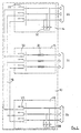
La figure 1 représente le schéma électrique d'un tableau triphasé, à cellules d'arrivées équipées d'un dispositif court-circuiteur d'arc.Figure 1 shows the electrical diagram of a three-phase switchboard, with inlet cells equipped with an arc shorting device.
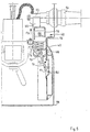
La figure 2 est une vue en coupe du dispositif court-circuiteur selon la ligne 2-2 de la figure 3, le dispositif court-circuiteur étant en position d'ouverture.Figure 2 is a sectional view of the short-circuiting device along line 2-2 of the figure 3, the short-circuiting device being in the open position.
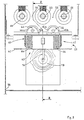
La figure 3 montre une vue en élévation du dispositif court-circuiteur, représenté en position d'ouverture.FIG. 3 shows an elevation view of the short-circuiting device, shown in open position.
La figure 4 est une vue identique à la figure 3 en position de fermeture du dispositif court-circuiteur.Figure 4 is a view identical to Figure 3 in the closed position of the short-circuiting device.
La figure 5 est une vue identique à la figure 2 en position de fermeture du dispositif court-circuiteur.Figure 5 is a view identical to Figure 2 in the closed position of the short-circuiting device.
Sur la figure 1, un tableau électrique 10 triphasé à moyenne ou haute tension est composé
de deux unités fonctionnelles ou cellules d'arrivée 12, 14 interconnectées électriquement par
un jeu de barres 18 commun à une troisième unité fonctionnelle ou cellule 16 de départ et
de protection. La structure générale du tableau 10 est décrite à titre d'exemple dans le
brevet français 2.507.835 de la demanderesse.In FIG. 1, a three-phase medium or high voltage
Chaque cellule d'arrivée 12, 14 comporte un interrupteur ou disjoncteur triphasé 20, 22 à
trois positions, raccordé entre le jeu de barres 18 et des câbles d'entrée 24, 26 connectés au
réseau, et un dispositif court-circuiteur d'arc 28, 30, qui sera décrit en détail par la suite.Each
La cellule départ 16 comprend un interrupteur triphasé 32 à trois positions, connecté par des
coupe-circuits à fusibles 34 à des câbles de sortie 36 pour l'alimentation d'un récepteur,
notamment un transformateur (non représenté). Il est clair que l'ensemble interrupteur 32 et
coupe-circuits à fusibles 34 peut être remplacé par un disjoncteur.The flow cell 16 comprises a three-
Chaque interrupteur 20, 22, 32 est doté par phase d'un contact mobile coopérant avec un
mécanisme pour occuper soit une position de fermeture, soit une position d'ouverture, soit
une position de mise à la terre.Each
La totalité des parties conductrices sous tension de l'équipement, est logé dans une
enveloppe 38 métallique et fermée, remplie de gaz isolant à rigidité diélectrique élevée,
notamment de l'hexafluorure de soufre SF6. All of the live conductive parts of the equipment are housed in a
metallic and closed
En référence aux figures 2 à 5, le dispositif court-circuiteur 28 d'arc de la cellule d'arrivée
12, est identique à celui 30 de l'autre cellule d'arrivée 14, et est entièrement logé à
l'intérieur de l'enveloppe 38 étanche. Un châssis 40 fixe est solidarisé à la paroi interne de
l'enveloppe 38, et sert de support au dispositif court-circuiteur 28, lequel comporte un
équipage mobile 42 ayant une paire de contacts 44, 46 en ponts coopérant avec trois
contacts fixes 48, 50, 52 agencés sur les parties internes des traversées 54 en liaison avec
les câbles d'entrée 24 des phases correspondantes.Referring to Figures 2 to 5, the
Les contacts fixes 48, 50, 52 présentent une section cylindrique, en étant séparés les uns des
autres à l'intérieur de l'enveloppe 38 par deux intervalles 56, 58 de pontage (figure 3) ayant
des largeurs identiques.The
Chaque contact en pont 44, 46 de l'équipage mobile 42 est équipé de deux rampes 44a,
44b; 46a, 46b latérales, faisant entre elles un angle aigu, pour former un coin venant
s'insérer dans l'intervalle 56, 58 correspondant en position de fermeture (figure 4). Les
faces latérales du coin viennent en engagement contre deux génératrices parallèles des
contacts fixes 48, 50, 52 cylindriques.Each bridge contact 44, 46 of the
A l'équipage mobile 42 est associé un mécanisme 60 à accumulation d'énergie, comprenant
un guide télescopique 62 de support de deux ressorts 64, 66 de compression, et un levier
d'accrochage 68 monté à pivotement limité sur un axe 70 entre une position armée (figure
2) et une position déclenchée (figure 5). Les deux ressorts 64, 66 prennent appui sur le
châssis 40 en sollicitant le coulisseau 72 mobile du guide télescopique 62 en direction des
contacts fixes 48, 50, 52, les contacts en pont 44, 46 étant agencés sur le coulisseau 72 à
l'opposé des ressorts 64, 66.The moving
Le levier d'accrochage 68 comporte un crochet 74 à bord interne arrondi coopérant en
position armée avec un galet 75 de retenue solidaire du coulisseau 72. A l'opposé du
crochet 74 se trouve une languette 76 de commande pilotée par un dispositif de
déclenchement à détecteur de pression 78, lequel libère le levier d'accrochage 68 en
sollicitant le crochet 74 vers la position déclenchée en cas d'élévation rapide de la pression
du gaz SF6 à l'intérieur de l'enveloppe 38.The
Le détecteur de pression 78 est logé à l'intérieur de l'enveloppe 38, et est pourvu d'une
membrane 80 en matériau déformable étanche, destinée à transformer la variation de
pression en un effort mécanique F1 exercé sur la languette 76 de commande du levier
d'accrochage 68. La membrane 80 est montée à étanchéité sur une ouverture d'une chambre
82 auxiliaire communiquant avec le volume interne de l'enveloppe 38 à travers un orifice
84 calibré de décompression, le volume de référence de la chambre 82 étant inférieur au
volume restant de l'enveloppe 38. Le débit de fuite par l'orifice 84 calibré permet d'égaliser
des variations de pression lentes entre les deux volumes, par exemple suite à des variations
de température, et à éviter toute rupture de la membrane 80 lors des opérations de mise sous
vide et de remplissage de l'enveloppe 38 par le gaz isolant SF6.The pressure detector 78 is housed inside the
La membrane 80 et la languette 76 du levier d'accrochage 68 sont protégées des parties sous
tension par un capot 86 en matériau conducteur, se trouvant au potentiel de la terre. La
présence de ce capot 86 améliore la tenue diélectrique du tableau 10 et place le détecteur de
pression 78 dans une zone à champ électrique quasi-nul, ce qui évite tout amorçage d'un arc
interne entre les parties sous tension, et un élément sensible du dispositif court-circuiteur
28.The
La zone de verrouillage du galet 75 de retenue par le levier d'accrochage 68 est située dans
une position médiane, et notamment dans le plan central de symétrie des contacts en pont
44, 46, et des ressorts 64, 66, de manière à obtenir une répartition uniforme de l'effort de
maintien du coulisseau 72 pour l'action de compression des ressorts 64, 66 en position
armée du mécanisme 60.The locking zone of the
Les contacts en pont 44, 46 et les contacts fixes 48, 50, 52 sont réalisés en cuivre, sans
revêtement spécial.The bridge contacts 44, 46 and the
Le fonctionnement du dispositif court-circuiteur 28 selon l'invention est le suivant :
Pendant la période de fonctionnement normal du tableau électrique 10, la pression du gaz
SF6 à l'intérieur de l'enveloppe 38 est constante, et atteint une valeur voisine de 1 à 2 bars.
Les contacts en pont 44, 46 sont ouverts (figures 2 et 3), et sont maintenus en permanence
dans cette position par l'action de verrouillage du coulisseau 72 dans l'état armé du
mécanisme 60 à accumulation d'énergie.The operation of the short-
En cas de défaillance de l'isolation gazeuse à l'intérieur de l'enveloppe 38, un amorçage
peut se produire, par exemple entre des conducteurs du jeu de barres 18, ce qui entraíne la
formation d'un arc interne, et une élévation rapide de la pression du gaz SF6 à l'intérieur de
l'enveloppe 38. Il en résulte un différentiel de pression par rapport au volume de référence
de la chambre 82 auxiliaire, provoquant l'enfoncement de la membrane 80 dans le sens de
la flèche F1 (figure 5). Le mouvement d'enfoncement de la membrane 80 entraíne le
pivotement du levier d'accrochage 68 dans le sens de la flèche F2 autour de l'axe 70, de
manière à libérer le galet 75 pour le passage du mécanisme 60 à l'état déclenché. In the event of failure of the gas insulation inside the
La détente des ressorts 64, 66 propulse le coulisseau 72 de l'équipage mobile 42 dans le
sens de la flèche F3 (figure 5), ce qui entraíne l'insertion rapide des deux ponts de contact
44, 46 dans les intervalles 56, 58 entre les trois contacts fixes 48, 50, 52. La fermeture des
contacts provoque le court-circuitage des trois phases, et l'extinction de l'arc interne lorsque
ce dernier est alimenté par le réseau 24. L'arc est shunté par un chemin conducteur solide
de faible impédance constituant un court-circuit entre les conducteurs de phase de
l'équipement électrique.The relaxation of the
La forme en coin des ponts de contacts 44, 46 permet d'obtenir des pressions de contact
supérieures à la poussée des ressorts 64, 66, et de résister aux efforts de répulsion
électrodynamique sans recourir à des ressorts surdimensionnés. Après la fermeture du
dispositif court-circuiteur 28, le dimensionnement spécifique des contacts fixes 48, 50, 52 et
des ponts de contact 44, 46 leur permet de supporter le courant de court-circuit pendant la
durée correspondant au délai d'intervention des protections amont du réseau.The wedge shape of the
La présence du capot 86 conducteur relié à la terre confine une zone à champ électrique
nul, dans laquelle sont disposés les éléments sensibles du détecteur de pression 78. L'arc
interne n'arrive pas à pénétrer dans cette zone, et le fonctionnement du dispositif court-circuiteur
28 est assuré en toute sécurité, indépendamment du lieu d'apparition de l'arc à
l'intérieur de l'enveloppe 38.The presence of the grounded
La structure du dispositif court-circuiteur 28 prend en compte les exigences suivantes ;
- absence de fonctionnement intempestif sous l'action des différents agents susceptibles d'affecter l'équipement électrique;
- fonctionnement assuré en cas d'arc interne d'intensité et de durée comprises entre des valeurs prédéterminées et assignées par le constructeur.
- absence of untimely operation under the action of the various agents likely to affect the electrical equipment;
- operation ensured in the event of an internal arc of intensity and duration between predetermined values and assigned by the manufacturer.
Pour l'installation du tableau sur le site, il est possible de cadenasser les dispositifs court-circuiteurs
28, 30 en position ouvert, en associant des moyens de blocage au levier
d'accrochage 68 de manière à empêcher le déclenchement intempestif du mécanisme 60 à
accumulation en présence de chocs mécaniques pouvant apparaítre lors de la manipulation
ou du transport du tableau.For the installation of the switchboard on the site, it is possible to padlock the short-circuiting
Il est clair que le coulisseau du mécanisme 60 pourrait être remplacé par un équipage
mobile pivotant.It is clear that the slide of
Claims (7)
- A high voltage multipole electrical switchgear apparatus having live conducting parts housed in a sealed metallic enclosure (38) filled with high dielectric strength insulating gas, notably sulphur hexafluoride, said switchgear apparatus being equipped with an arc short-circuiting device (28, 30) rendered active in the event of an intemal flashover following a failure of the gas insulation, and comprising :characterized in thatan energy storage mechanism (60) associated to a movable assembly (42) supporting first contact means (44, 46) designed to cooperate with second contact means (48, 50, 52) fixed to the conducting parts,a tripping device equipped with a latching lever (68) movable between a loaded position corresponding to separation of said first and second contact means and a tripped position releasing the mechanism (60) for closing of said contact means,a pressure detector (78) sensitive to the variation of the gas pressure inside the enclosure (38) to cause the latching lever (68) to move from the loaded position to the tripped position beyond a preset threshold following formation of an intemal arc,all the component parts of the mechanism (60), tripping device, and pressure detector (78) being entirely contained inside the closed enclosure (38),
the second contact means (48, 50, 52) are formed by three fixed studs, of appreciably cylindrical cross sections, separated one from the other by two bridging gaps (56, 58), and that the first contact means (44, 46) comprise a pair of movable contact bridges designed to be inserted in the tripped position of the latching lever (68) into the corresponding gaps (56, 58) to come into engagement with generating lines of the fixed studs performing short-circuiting between the phases of the conducting parts. - The electrical switchgear apparatus according to claim 1, characterized in that each contact bridge (44, 46) is shaped as a wedge having two ramps (44a, 44b; 46a, 46b) arranged at an acute angle facing the corresponding bridging gap (56, 58), in such a way as to withstand the electrodynamic repulsion forces when short-circuiting occurs.
- The electrical switchgear apparatus according to claim 1 or 2, characterized in that the latching lever (68) comprises a hook (74) cooperating in the loaded position with a checking roller (75) fixed to a slide (72) of the movable assembly (42), the locking zone of the roller (75) being situated in the central plane of symmetry of the two contact bridges (44, 46), and that the mechanism (60) is provided with two springs (64, 66) urging the slide (72) in the direction of the second contact means (48, 50, 52) when the latching lever (68) moves to the tripped position.
- The electrical switchgear apparatus according to one of the claims 1 to 3, characterized in that the pressure detector (78) is composed of a membrane (80) made of deformable material, mounted in leaktight manner on an opening of an auxiliary chamber (82), which chamber communicates with the remaining volume of the enclosure (38) via a calibrated decompression orifice (84), the reference volume of said chamber (82) being smaller than that of the enclosure (38).
- The electrical switchgear apparatus according to claim 4, characterized in that the membrane of the pressure detector (78) is coupled to an operating tongue (76) of the pivoting latching lever (68).
- The electrical switchgear apparatus according to one of the claims 1 to 5, characterized in that a cover (86) made of conducting material covers the pressure detector (78) to form a zone of almost nil electrical field, said cover (86) being electrically earthed.
- The electrical switchgear apparatus according to one of the claims 1 to 6, characterized in that the short-circuiting device (28, 30) is supported by a frame (40) secured to the internal wall of the metallic enclosure (38).
Applications Claiming Priority (2)
| Application Number | Priority Date | Filing Date | Title |
|---|---|---|---|
| FR9412377A FR2725844B1 (en) | 1994-10-12 | 1994-10-12 | HIGH VOLTAGE ELECTRICAL APPARATUS WITH GAS INSULATION EQUIPPED WITH AN ARC SHORT CIRCUIT DEVICE |
| FR9412377 | 1994-10-12 |
Publications (2)
| Publication Number | Publication Date |
|---|---|
| EP0707364A1 EP0707364A1 (en) | 1996-04-17 |
| EP0707364B1 true EP0707364B1 (en) | 1998-11-04 |
Family
ID=9467933
Family Applications (1)
| Application Number | Title | Priority Date | Filing Date |
|---|---|---|---|
| EP19950410093 Expired - Lifetime EP0707364B1 (en) | 1994-10-12 | 1995-09-05 | High voltage, gas insulated electric switchgear equipped with an arc short-circuiting device |
Country Status (7)
| Country | Link |
|---|---|
| EP (1) | EP0707364B1 (en) |
| CN (1) | CN1059978C (en) |
| DE (1) | DE69505772T2 (en) |
| ES (1) | ES2126235T3 (en) |
| FR (1) | FR2725844B1 (en) |
| NO (1) | NO308390B1 (en) |
| TW (1) | TW303473B (en) |
Cited By (2)
| Publication number | Priority date | Publication date | Assignee | Title |
|---|---|---|---|---|
| EP1806817A1 (en) | 2006-01-09 | 2007-07-11 | Luis Gonzalo Flores Losada | Oil-immersed electrical equipment with a short-circuiting safety device |
| CN104409970A (en) * | 2014-11-28 | 2015-03-11 | 国家电网公司 | Switch cabinet |
Families Citing this family (4)
| Publication number | Priority date | Publication date | Assignee | Title |
|---|---|---|---|---|
| DE10031561A1 (en) * | 2000-06-28 | 2002-01-10 | Alstom | Arc limiter for a gas-insulated switchgear |
| FR2955983A1 (en) * | 2010-02-01 | 2011-08-05 | Mining Res & Dev | DEVICE FOR PROTECTING AN ELECTRIC ARC |
| EP2551974A1 (en) | 2011-07-25 | 2013-01-30 | Eaton Industries (Netherlands) B.V. | Switching installation with pressure controlled short-circuit device |
| DE102013109938A1 (en) * | 2013-09-10 | 2015-03-12 | Fritz Driescher KG Spezialfabrik für Elektrizitätswerksbedarf GmbH & Co | Switchgear with arc fault limiter |
Family Cites Families (4)
| Publication number | Priority date | Publication date | Assignee | Title |
|---|---|---|---|---|
| FR2507835A1 (en) | 1981-06-16 | 1982-12-17 | Merlin Gerin | GAS INSULATED SHIELDED CELL FOR MEDIUM VOLTAGE POWER STATION |
| DE3131417A1 (en) * | 1981-08-07 | 1983-02-24 | Brown, Boveri & Cie Ag, 6800 Mannheim | Actuating device for an earthing switch or a short-circuiting switch in switching installation parts (which are encapsulated without being pressurised) of high-voltage or medium-voltage switching and distribution installations |
| FR2649531B1 (en) * | 1989-07-04 | 1995-11-10 | Alsthom Gec | HIGH OR MEDIUM VOLTAGE CIRCUIT BREAKER |
| NO175173C (en) * | 1992-02-03 | 1994-09-07 | Abb Distribusjon As | Device for automatic earth terminals |
-
1994
- 1994-10-12 FR FR9412377A patent/FR2725844B1/en not_active Expired - Fee Related
-
1995
- 1995-09-05 DE DE1995605772 patent/DE69505772T2/en not_active Expired - Lifetime
- 1995-09-05 EP EP19950410093 patent/EP0707364B1/en not_active Expired - Lifetime
- 1995-09-05 ES ES95410093T patent/ES2126235T3/en not_active Expired - Lifetime
- 1995-09-26 TW TW84110029A patent/TW303473B/zh active
- 1995-10-11 NO NO954044A patent/NO308390B1/en not_active IP Right Cessation
- 1995-10-12 CN CN95116157A patent/CN1059978C/en not_active Expired - Fee Related
Cited By (3)
| Publication number | Priority date | Publication date | Assignee | Title |
|---|---|---|---|---|
| EP1806817A1 (en) | 2006-01-09 | 2007-07-11 | Luis Gonzalo Flores Losada | Oil-immersed electrical equipment with a short-circuiting safety device |
| US7755868B2 (en) | 2006-01-09 | 2010-07-13 | Luis Gonzalo Flores Losada | Electrical equipment for distribution network |
| CN104409970A (en) * | 2014-11-28 | 2015-03-11 | 国家电网公司 | Switch cabinet |
Also Published As
| Publication number | Publication date |
|---|---|
| NO954044L (en) | 1996-04-15 |
| DE69505772T2 (en) | 1999-05-27 |
| NO308390B1 (en) | 2000-09-04 |
| FR2725844B1 (en) | 1996-12-13 |
| NO954044D0 (en) | 1995-10-11 |
| FR2725844A1 (en) | 1996-04-19 |
| CN1129846A (en) | 1996-08-28 |
| CN1059978C (en) | 2000-12-27 |
| ES2126235T3 (en) | 1999-03-16 |
| DE69505772D1 (en) | 1998-12-10 |
| TW303473B (en) | 1997-04-21 |
| EP0707364A1 (en) | 1996-04-17 |
Similar Documents
| Publication | Publication Date | Title |
|---|---|---|
| EP0225207B1 (en) | Cinematic transmission chain between the control mechanism and the poles of an electric circuit breaker with a moulded insulating casing | |
| KR101267955B1 (en) | Low-voltage, medium-voltage or high-voltage switchgear assembly having a short-circuiting system | |
| EP0847586B1 (en) | High voltage hybrid circuit-breaker | |
| FR2582857A1 (en) | SINGLE POLE AND NEUTRAL CIRCUIT BREAKER WITH SHUNT EFFECT | |
| EP0444568B1 (en) | Circuit breaker assisted by varistor | |
| EP0707364B1 (en) | High voltage, gas insulated electric switchgear equipped with an arc short-circuiting device | |
| CA2044517C (en) | Integral varistor airconnect switch | |
| EP0270389B1 (en) | Gas insulated multiphase rotating switch | |
| EP0277848B1 (en) | Multiphase circuit breaker with self-expansion having per phase a gas-insulated arc extinguishing chamber | |
| EP0924827B1 (en) | Gas-insulated, medium voltage switchgear cell with increased dielectric strength | |
| EP0165184B1 (en) | Gas-insulated three-phase encapsulated switching installation | |
| FR2703825A1 (en) | Molded case circuit breaker with adapter for current transformers. | |
| EP0053973B1 (en) | Miniature circuit breaker with high rupture capacity | |
| EP1122848B1 (en) | Improved device protecting against internal faults in a three-phase transformer | |
| EP1842269A2 (en) | Electrical installation protection device with improved interrupting capacity | |
| EP1953788B1 (en) | Device for protecting against voltage surges with a mobile electrode with system for unlocking the disconnection device | |
| EP0130851A1 (en) | Protection apparatus against overvoltages in electrical low-voltage installations or networks | |
| EP0338382B1 (en) | Cells for enclosed middle and high voltage stations, and station composed of such cells | |
| EP0433183A1 (en) | Three-pole gasinsulated high tension circuit breaker | |
| FR2678770A1 (en) | Hybrid high-voltage circuit breaker with high arc voltage | |
| EP0348312B1 (en) | Shielded station for a high voltage network | |
| FR2547107A1 (en) | Shielded isolating breaker | |
| FR2553926A1 (en) | High-voltage circuit breaker with closure resistors | |
| FR2589625A1 (en) | Kinematic chain for transmission beween the control mechanism and the poles of an electric circuit breaker | |
| FR2650078A1 (en) | System for detecting a fault in the insulation of a medium voltage line for distributing electrical power |
Legal Events
| Date | Code | Title | Description |
|---|---|---|---|
| PUAI | Public reference made under article 153(3) epc to a published international application that has entered the european phase |
Free format text: ORIGINAL CODE: 0009012 |
|
| AK | Designated contracting states |
Kind code of ref document: A1 Designated state(s): DE ES GB IT NL SE |
|
| 17P | Request for examination filed |
Effective date: 19960924 |
|
| GRAG | Despatch of communication of intention to grant |
Free format text: ORIGINAL CODE: EPIDOS AGRA |
|
| 17Q | First examination report despatched |
Effective date: 19971117 |
|
| GRAG | Despatch of communication of intention to grant |
Free format text: ORIGINAL CODE: EPIDOS AGRA |
|
| GRAH | Despatch of communication of intention to grant a patent |
Free format text: ORIGINAL CODE: EPIDOS IGRA |
|
| GRAH | Despatch of communication of intention to grant a patent |
Free format text: ORIGINAL CODE: EPIDOS IGRA |
|
| GRAA | (expected) grant |
Free format text: ORIGINAL CODE: 0009210 |
|
| AK | Designated contracting states |
Kind code of ref document: B1 Designated state(s): DE ES GB IT NL SE |
|
| REF | Corresponds to: |
Ref document number: 69505772 Country of ref document: DE Date of ref document: 19981210 |
|
| GBT | Gb: translation of ep patent filed (gb section 77(6)(a)/1977) |
Effective date: 19990112 |
|
| ITF | It: translation for a ep patent filed |
Owner name: EUROPATENT S.A.S. |
|
| REG | Reference to a national code |
Ref country code: ES Ref legal event code: FG2A Ref document number: 2126235 Country of ref document: ES Kind code of ref document: T3 |
|
| PLBE | No opposition filed within time limit |
Free format text: ORIGINAL CODE: 0009261 |
|
| STAA | Information on the status of an ep patent application or granted ep patent |
Free format text: STATUS: NO OPPOSITION FILED WITHIN TIME LIMIT |
|
| 26N | No opposition filed | ||
| REG | Reference to a national code |
Ref country code: GB Ref legal event code: IF02 |
|
| PGFP | Annual fee paid to national office [announced via postgrant information from national office to epo] |
Ref country code: GB Payment date: 20020904 Year of fee payment: 8 |
|
| PGFP | Annual fee paid to national office [announced via postgrant information from national office to epo] |
Ref country code: ES Payment date: 20020927 Year of fee payment: 8 |
|
| PG25 | Lapsed in a contracting state [announced via postgrant information from national office to epo] |
Ref country code: GB Free format text: LAPSE BECAUSE OF NON-PAYMENT OF DUE FEES Effective date: 20030905 |
|
| PG25 | Lapsed in a contracting state [announced via postgrant information from national office to epo] |
Ref country code: ES Free format text: LAPSE BECAUSE OF NON-PAYMENT OF DUE FEES Effective date: 20030906 |
|
| GBPC | Gb: european patent ceased through non-payment of renewal fee | ||
| REG | Reference to a national code |
Ref country code: ES Ref legal event code: FD2A Effective date: 20030906 |
|
| PG25 | Lapsed in a contracting state [announced via postgrant information from national office to epo] |
Ref country code: IT Free format text: LAPSE BECAUSE OF NON-PAYMENT OF DUE FEES;WARNING: LAPSES OF ITALIAN PATENTS WITH EFFECTIVE DATE BEFORE 2007 MAY HAVE OCCURRED AT ANY TIME BEFORE 2007. THE CORRECT EFFECTIVE DATE MAY BE DIFFERENT FROM THE ONE RECORDED. Effective date: 20050905 |
|
| PGFP | Annual fee paid to national office [announced via postgrant information from national office to epo] |
Ref country code: NL Payment date: 20090903 Year of fee payment: 15 |
|
| PGFP | Annual fee paid to national office [announced via postgrant information from national office to epo] |
Ref country code: DE Payment date: 20100918 Year of fee payment: 16 |
|
| REG | Reference to a national code |
Ref country code: NL Ref legal event code: V1 Effective date: 20110401 |
|
| PG25 | Lapsed in a contracting state [announced via postgrant information from national office to epo] |
Ref country code: NL Free format text: LAPSE BECAUSE OF NON-PAYMENT OF DUE FEES Effective date: 20110401 |
|
| REG | Reference to a national code |
Ref country code: DE Ref legal event code: R119 Ref document number: 69505772 Country of ref document: DE Effective date: 20130403 |
|
| PG25 | Lapsed in a contracting state [announced via postgrant information from national office to epo] |
Ref country code: DE Free format text: LAPSE BECAUSE OF NON-PAYMENT OF DUE FEES Effective date: 20130403 |
|
| PGFP | Annual fee paid to national office [announced via postgrant information from national office to epo] |
Ref country code: SE Payment date: 20130911 Year of fee payment: 19 |
|
| REG | Reference to a national code |
Ref country code: SE Ref legal event code: EUG |
|
| PG25 | Lapsed in a contracting state [announced via postgrant information from national office to epo] |
Ref country code: SE Free format text: LAPSE BECAUSE OF NON-PAYMENT OF DUE FEES Effective date: 20140906 |