EP0707176A2 - Tension lever flap valve for conduits having large cross-section - Google Patents
Tension lever flap valve for conduits having large cross-section Download PDFInfo
- Publication number
- EP0707176A2 EP0707176A2 EP95115845A EP95115845A EP0707176A2 EP 0707176 A2 EP0707176 A2 EP 0707176A2 EP 95115845 A EP95115845 A EP 95115845A EP 95115845 A EP95115845 A EP 95115845A EP 0707176 A2 EP0707176 A2 EP 0707176A2
- Authority
- EP
- European Patent Office
- Prior art keywords
- lever
- flap
- drive shaft
- tension lever
- approximately
- Prior art date
- Legal status (The legal status is an assumption and is not a legal conclusion. Google has not performed a legal analysis and makes no representation as to the accuracy of the status listed.)
- Granted
Links
Images

Classifications
-
- F—MECHANICAL ENGINEERING; LIGHTING; HEATING; WEAPONS; BLASTING
- F16—ENGINEERING ELEMENTS AND UNITS; GENERAL MEASURES FOR PRODUCING AND MAINTAINING EFFECTIVE FUNCTIONING OF MACHINES OR INSTALLATIONS; THERMAL INSULATION IN GENERAL
- F16K—VALVES; TAPS; COCKS; ACTUATING-FLOATS; DEVICES FOR VENTING OR AERATING
- F16K11/00—Multiple-way valves, e.g. mixing valves; Pipe fittings incorporating such valves
- F16K11/02—Multiple-way valves, e.g. mixing valves; Pipe fittings incorporating such valves with all movable sealing faces moving as one unit
- F16K11/04—Multiple-way valves, e.g. mixing valves; Pipe fittings incorporating such valves with all movable sealing faces moving as one unit comprising only lift valves
- F16K11/052—Multiple-way valves, e.g. mixing valves; Pipe fittings incorporating such valves with all movable sealing faces moving as one unit comprising only lift valves with pivoted closure members, e.g. butterfly valves
-
- F—MECHANICAL ENGINEERING; LIGHTING; HEATING; WEAPONS; BLASTING
- F23—COMBUSTION APPARATUS; COMBUSTION PROCESSES
- F23L—SUPPLYING AIR OR NON-COMBUSTIBLE LIQUIDS OR GASES TO COMBUSTION APPARATUS IN GENERAL ; VALVES OR DAMPERS SPECIALLY ADAPTED FOR CONTROLLING AIR SUPPLY OR DRAUGHT IN COMBUSTION APPARATUS; INDUCING DRAUGHT IN COMBUSTION APPARATUS; TOPS FOR CHIMNEYS OR VENTILATING SHAFTS; TERMINALS FOR FLUES
- F23L11/00—Arrangements of valves or dampers after the fire
-
- Y—GENERAL TAGGING OF NEW TECHNOLOGICAL DEVELOPMENTS; GENERAL TAGGING OF CROSS-SECTIONAL TECHNOLOGIES SPANNING OVER SEVERAL SECTIONS OF THE IPC; TECHNICAL SUBJECTS COVERED BY FORMER USPC CROSS-REFERENCE ART COLLECTIONS [XRACs] AND DIGESTS
- Y10—TECHNICAL SUBJECTS COVERED BY FORMER USPC
- Y10T—TECHNICAL SUBJECTS COVERED BY FORMER US CLASSIFICATION
- Y10T137/00—Fluid handling
- Y10T137/8593—Systems
- Y10T137/877—With flow control means for branched passages
- Y10T137/87788—With valve or movable deflector at junction
- Y10T137/87812—Pivoted valve or deflector
Definitions
- the invention relates to a cocking flap, in particular for large cable cross-sections, with a flap housing and a flap wing that can be swiveled between two limit switch positions within a swivel angle range of approximately 90 °, which has a drive shaft, a tensioning lever sitting thereon and one with the tensioning lever and, on the other hand, approximately in the center the flap wing articulated rod can be driven.
- Tension lever flaps of this type are commonly used in flue gas cleaning and gas turbine systems because, on the one hand, they enable the flap wing to be actuated with a favorable torque and, on the other hand, they intercept the relatively far-reaching flap wing approximately in the center.
- the cocking lever mechanism is generally driven by electric drives, double-cylinder piston swivel drives or by several cylinder-piston units which are controlled in both swivel directions by means of special valve arrangements.
- a cocking lever flap with an electric drive is disclosed in DE-OS 38 13 663.
- a double-cylinder piston swivel drive is described in DE-OS 42 39 423.
- DE-PS 40 33 663 shows a flap actuator consisting of two cylinder piston units with associated control valves.
- the aforementioned drive systems are able to actuate the flap wing over the entire swivel angle with the required torque and thereby move the rotation angle ⁇ of the tension lever provided in the known tension lever flaps between approximately 170 ° and 210 °.
- Electric drives work relatively slowly and are expensive to buy.
- Double cylinder piston swivel drives or cylinder piston units, which are controlled via special valve arrangements, are also expensive and moreover prone to failure.
- the invention has for its object to remedy these disadvantages and to provide a cocking lever flap of the type mentioned, which is operable with a design that is as simple as possible in terms of design and control technology, cylinder-piston drive, trouble-free and with relatively short switching times.
- This object is achieved in that the axis of rotation of the drive shaft or the clamping lever is offset so far in the direction of the pivot axis of the flap wing that the angle of rotation ⁇ of the clamping lever between the two end switch positions of the flap wing is between 90 ° and 150 °.
- Limiting the angle of rotation ⁇ to the specified angle range makes it possible to drive the tensioning lever with a single cylinder-piston unit, because its working stroke is sufficient to move the angle of rotation range between 90 ° and 150 ° provided according to the invention.
- Such a drive is known to be very robust and can be switched over quickly with the simplest possible control means. This ensures that the system is largely free from interference. Due to the resulting torques on the drive shaft, an angle of rotation ⁇ of the clamping lever between 125 ° and 130 ° is preferred according to the invention.
- the invention provides for the distance between the axis of rotation of the tensioning lever and the pivot axis of the flap wing to be such that it is approximately 1/6 of the inside width of the line cross section.
- the measures according to the invention enable the use of a cylinder piston unit consisting of two synchronous cylinder piston units lying parallel to one another, which act in opposite directions on a double-armed lever seated on the drive shaft. In this way it is possible to drive the drive shaft without bending moment.
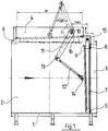
- 1 consists of a flap housing 1 with three line connections 2, 3 and 4, of which the line connections 3 and 4 are provided with sealing seats 5 and 6, respectively.
- a flap wing 7 with sealing elements 8 and 9 can be swiveled in a swivel angle range of approximately 90 ° between two limit switch positions, in which the sealing elements 8, 9 of the flap wing 7 are pressed against the sealing seats 5 and 6 of the flap housing 1.
- the flap wing 7 can be driven via a drive shaft 10, a tensioning lever 11 sitting thereon and an articulated rod 12.
- the articulated rod 12 is articulated at one end 13 to the tensioning lever 11 and at the other end 14 approximately centrally with the flap wing 7.
- the pivot axis 15 of the flap wing 7 is arranged between the two line connections 3 and 4 on the outer edge of the flap wing 7.
- the drive shaft 10 is mounted in the area of the line connection 4 so that the distance between the axis of rotation 16 of the drive shaft 10 and the pivot axis 15 of the flap 7 is approximately 1/6 of the clear nominal diameter DN of the line cross section.
- the bearing of the drive shaft 10 is arranged just above the level of the sealing seat 6. In the limit switch position shown in dashed lines with the clamping lever retracted, the axis of rotation 16 of the drive shaft 10 and the articulated axis 14 of the articulated rod 12 are approximately the same distance from the plane of the sealing seat 6.
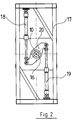
- the drive shaft 10 is driven with the aid of the drive units shown in FIG. 2.
- This consists of a frame 17 and two articulated cylinder piston units 18 and 19, which are arranged parallel to each other in the frame 17 and whose piston rods each engage a lever arm of a double-armed drive lever 20 which sits on the drive shaft 10 in a rotationally fixed manner.
- the two cylinder piston units 18, 19 work synchronously and in opposite directions. Your working stroke is dimensioned such that the double-armed drive lever 20 can be rotated through each of the cylinder piston units 18, 19 by an angle of rotation ⁇ of approximately 125 ° or 130 °.
- the drive shaft 10 is driven without bending moment due to the synchronous and counter-rotating cylinder piston units 18, 19.
- the tension lever flap according to FIG. 3 differs from the tension lever flap according to FIG. 1 only in that the tension lever 11 and the articulated rod 12 have a different length, the tension lever 11 being longer than the articulated rod 12.
Landscapes
- Engineering & Computer Science (AREA)
- General Engineering & Computer Science (AREA)
- Mechanical Engineering (AREA)
- Chemical & Material Sciences (AREA)
- Combustion & Propulsion (AREA)
- Lift Valve (AREA)
- Mechanically-Actuated Valves (AREA)
- Preventing Unauthorised Actuation Of Valves (AREA)
Abstract
Description
Die Erfindung betrifft eine Spannhebeklappe, insbesondere für große Leitungsquerschnitte, mit einem Klappengehäuse und einem darin zwischen zwei Endschaltstellungen in einem Schwenkwinkelbereich von ca. 90° schwenkbaren Klappenflügel, der über eine Antriebswelle, einen daraufsitzenden Spannhebel und eine einerseits mit dem Spannhebel und andererseits annähernd mittig mit dem Klappenflügel gelenkig verbundene Gelenkstange antreibbar ist.The invention relates to a cocking flap, in particular for large cable cross-sections, with a flap housing and a flap wing that can be swiveled between two limit switch positions within a swivel angle range of approximately 90 °, which has a drive shaft, a tensioning lever sitting thereon and one with the tensioning lever and, on the other hand, approximately in the center the flap wing articulated rod can be driven.
Spannhebelklappen dieser Art finden bekantlich Anwendung in Rauchgas-Reinigungs- und Gasturbinenanlagen, weil sie zum einen die Betätigung des Klappenflügels mit einem günstigen Drehmoment ermöglichen und zum anderen den verhältnismäßig weit ausladenden Klappenflügel annähernd mittig abfangen.Tension lever flaps of this type are commonly used in flue gas cleaning and gas turbine systems because, on the one hand, they enable the flap wing to be actuated with a favorable torque and, on the other hand, they intercept the relatively far-reaching flap wing approximately in the center.
Der Spannhebelmechanismus wird im allgemeinen durch Elektroantriebe, Doppelzylinderkolben-Schwenkantriebe oder aber durch mehrere Zylinder-Kolbeneinheiten, die über spezielle Ventilanordnungen in beiden Schwenkrichtungen gesteuert werden, angetrieben. Eine Spannhebelklappe mit Elektroantrieb ist in der DE-OS 38 13 663 geoffenbart. Ein Doppelzylinderkolben-Schwenkantrieb ist in der DE-OS 42 39 423 beschrieben. Einen Spannklappenantrieb bestehend aus zwei Zylinderkolbeneinheiten mit dazugehörigen Steuerventilen zeigt die DE-PS 40 33 663.The cocking lever mechanism is generally driven by electric drives, double-cylinder piston swivel drives or by several cylinder-piston units which are controlled in both swivel directions by means of special valve arrangements. A cocking lever flap with an electric drive is disclosed in DE-OS 38 13 663. A double-cylinder piston swivel drive is described in DE-OS 42 39 423. DE-PS 40 33 663 shows a flap actuator consisting of two cylinder piston units with associated control valves.
Die vorgenannten Antriebssysteme sind zwar in der Lage, den Klappenflügel über den gesamten Schwenkwinkel mit dem erforderlichen Drehmoment zu betätigen und dabei den bei den vorbekannten Spannhebelklappen vorgesehenen Drehwinkel β des Spannhebels zwischen ca. 170° und 210° zu verfahren. Sie haben jedoch im einzelnen erhebliche Nachteile. Elektroantriebe arbeiten verhältnismäßig langsam und sind kostspielig in der Anschaffung. Doppelzylinderkolben-Schwenkantriebe oder Zylinderkolbeneinheiten, die über spezielle Ventilanordnungen gesteuert werden, sind ebenfalls kostspielig und außerdem störanfällig.The aforementioned drive systems are able to actuate the flap wing over the entire swivel angle with the required torque and thereby move the rotation angle β of the tension lever provided in the known tension lever flaps between approximately 170 ° and 210 °. However, they have considerable disadvantages in detail. Electric drives work relatively slowly and are expensive to buy. Double cylinder piston swivel drives or cylinder piston units, which are controlled via special valve arrangements, are also expensive and moreover prone to failure.
Der Erfindung liegt die Aufgabe zugrunde, diese Nachteile zu beheben und eine Spannhebelklappe der eingangs genannten Art zu schaffen, die mit einem konstruktiv und steuerungstechnisch möglichst einfachen Zylinder-Kolbenantrieb betriebssicher, störungsfrei und mit verhältnismäßig kurzen Schaltzeiten antreibbar ist.The invention has for its object to remedy these disadvantages and to provide a cocking lever flap of the type mentioned, which is operable with a design that is as simple as possible in terms of design and control technology, cylinder-piston drive, trouble-free and with relatively short switching times.
Diese Aufgabe wird erfindungsgemäß dadurch gelöst, daß die Drehachse der Antriebswelle bzw. des Spannhebels soweit in Richtung zur Schwenkachse des Klappenflügels hin versetzt ist, daß der Drehwinkel β des Spannhebels zwischen den beiden Endschaltstellungen des Klappenflügels zwischen 90° und 150° beträgt.This object is achieved in that the axis of rotation of the drive shaft or the clamping lever is offset so far in the direction of the pivot axis of the flap wing that the angle of rotation β of the clamping lever between the two end switch positions of the flap wing is between 90 ° and 150 °.
Die Begrenzung des Drehwinkels β auf den angegebenen Winkelbereich ermöglicht es, den Spannhebel mit einer einzigen Zylinder-Kolbeneinheit anzutreiben, weil deren Arbeitshub zum Verfahren des erfindungsgemäß vorgesehenen Drehwinkelbereiches zwischen 90° und 150° ausreichend ist. Ein solcher Antrieb ist bekanntlich sehr robust und läßt sich mit denkbar einfachen Steuermitteln schnell umschalten. Dadurch ist die weitgehende Störungsfreiheit des Systems gewährleistet. Aufgrund der sich dabei ergebenden Drehmomenten auf der Antriebswelle wird erfindungsgemäß ein Drehwinkel β des Spannhebels zwischen 125° und 130° bevorzugt.Limiting the angle of rotation β to the specified angle range makes it possible to drive the tensioning lever with a single cylinder-piston unit, because its working stroke is sufficient to move the angle of rotation range between 90 ° and 150 ° provided according to the invention. Such a drive is known to be very robust and can be switched over quickly with the simplest possible control means. This ensures that the system is largely free from interference. Due to the resulting torques on the drive shaft, an angle of rotation β of the clamping lever between 125 ° and 130 ° is preferred according to the invention.
Um diese Drehwinkelwerte zu erreichen, sieht die Erfindung vor, den Abstand zwischen der Drehachse des Spannhebels und der Schwenkachse des Klappenflügels so zu bemessen, daß er ca. 1/6 der lichten Weite des Leitungsquerschnittes beträgt. Diese simple konstruktive Maßnahme ermöglicht es, den Drehwinkel des Spannhebels erfindungsgemäß auf die vorstehend angegebenen Drehwinkelwerte zu beschränken, ohne daß die erforderlichen Drehmomente auf der Antriebswelle in nennenswertem Umfang höher werden.In order to achieve these rotation angle values, the invention provides for the distance between the axis of rotation of the tensioning lever and the pivot axis of the flap wing to be such that it is approximately 1/6 of the inside width of the line cross section. This simple design measure makes it possible, according to the invention, to limit the angle of rotation of the tensioning lever to the values of the angle of rotation given above, without the required torques on the drive shaft becoming appreciably higher.
Aus konstruktiven Gründen ist es im Rahmen der Erfindung vorteilhaft, wenn der Spannhebel und die Gelenkstange annähernd die gleiche Länge aufweisen, so daß bei eingefahrenem Hebelsystem der Spannhebel und die Gelenkstange zur Mittelsenkrechten annähernd den gleichen Winkel α 1 = α 2 bilden.For design reasons, it is advantageous within the scope of the invention if the tensioning lever and the articulated rod have approximately the same length, so that when the lever system is retracted, the tensioning lever and the articulated rod form approximately the same angle α 1 =
Es ist jedoch auch im Rahmen der Erfindung möglich, den Spannhebel länger als die Gelenkstange zu bemessen. Diese Maßnahme trägt dazu bei, den Drehwinkel β des Spannhebels zwischen den beiden Endschaltstellungen weiter zu verringern und kommt je nach Betriebsbedingungen dann in Frage, wenn ein etwas höheres Drehmoment zur Betätigung des Klappenflügels in Kauf genommen werden kann.However, it is also possible within the scope of the invention to dimension the tensioning lever longer than the joint rod. This measure helps to further reduce the angle of rotation β of the tensioning lever between the two limit switch positions and, depending on the operating conditions, comes into question when a somewhat higher torque for actuating the flap wing can be accepted.
Die erfindungsgemäßen Maßnahmen ermöglichen die Verwendung eines Zylinderkolbenaggregats bestehend aus zwei parallelzueinander liegenden, synchron arbeitenden Zylinderkolben-Einheiten, die gegenläufig auf einen auf der Antriebswelle sitzenden doppelarmigen Hebel angreifen. Auf diese Weise ist es möglich, die Antriebswelle biegemomentfrei anzutreiben.The measures according to the invention enable the use of a cylinder piston unit consisting of two synchronous cylinder piston units lying parallel to one another, which act in opposite directions on a double-armed lever seated on the drive shaft. In this way it is possible to drive the drive shaft without bending moment.
Es ist jedoch selbstverständlich gemäß der Erfindung ebenfalls möglich, die Antriebswelle durch eine einzige Zylinder-Kolben-Einheit über einen auf der Antriebswelle sitzenden einseitigen Hebel anzutreiben, weil der Arbeitshub der Zylinder-Kolben-Einheit zum Verfahren des erfindungsgemäßen Drehwinkels β ausreichend ist.However, it is of course also possible according to the invention to drive the drive shaft through a single cylinder-piston unit via a one-sided lever seated on the drive shaft, because the working stroke of the cylinder-piston unit is sufficient to move the angle of rotation β according to the invention.
Nachfolgend werden zwei Ausführungsbeispiele der erfindungsgemäßen Spannhebelklappe näher beschrieben.Two exemplary embodiments of the tension lever flap according to the invention are described in more detail below.
Es zeigen:
- Fig. 1
- eine Spannhebelklappe mit gleichlangem Spannhebel und Gelenkstange, im Längsschnitt dargestellt,
- Fig. 2
- das Antriebsaggregat für die Spannhebelklappe nach Fig. 1, in der Vorderansicht dargestellt, und
- Fig. 3
- eineVariante der Spannhebelklappe nach Fig. 1, deren Spannhebel länger als die Gelenkstange bemessen ist.
- Fig. 1
- a clamping lever flap with the same length clamping lever and articulated rod, shown in longitudinal section,
- Fig. 2
- the drive unit for the cocking lever flap according to FIG. 1, shown in the front view, and
- Fig. 3
- a variant of the clamping lever flap according to Fig. 1, the clamping lever is longer than the articulated rod.
Die Spannhebelklappe gemäß Fig. 1 besteht aus einem Klappengehäuse 1 mit drei Leitungsanschlüssen 2, 3 und 4, von denen die Leitungsanschlüsse 3 und 4 mit Dichtsitzen 5 bzw. 6 versehen sind.1 consists of a flap housing 1 with three
Im Klappengehäuse 1 ist ein Klappenflügel 7 mit Dichtelementen 8 und 9 in einem Schwenkwinkelbereich von ca. 90° zwischen zwei Endschaltstellungen schwenkbar, in denen die Dichtelemente 8, 9 des Klappenflügels 7 gegen die Dichtsitze 5 bzw. 6 des Klappengehäuses 1 angedrückt sind.In the flap housing 1, a
Der Klappenflügel 7 ist über eine Antriebswelle 10, einen daraufsitzenden Spannhebel 11 und eine Gelenkstange 12 antreibbar. Die Gelenkstange 12 ist an dem einen Ende 13 mit dem Spannhebel 11 und an dem anderen Ende 14 annähernd mittig mit dem Klappenflügel 7 gelenkig verbunden. Die Schwenkachse 15 des Klappenflügels 7 ist zwischen den beiden Leitungsanschlüssen 3 und 4 am Außenrand des Klappenflügels 7 angeordnet. Die Antriebswelle 10 ist im Bereich des Leitungsanschlusses 4 so gelagert, daß der Abstand zwischen der Drehachse 16 der Antriebswelle 10 und der Schwenkachse 15 des Klappenflügels 7 ca. 1/6 der lichten Nennweite DN des Leitungsquerschnitts beträgt. Die Lagerung der Antriebswelle 10 ist kurz oberhalb der Ebene des Dichtsitzes 6 angeordnet. In der gestrichelt dargestellten Endschaltstellung mit eingefahrenem Spannhebel liegen die Drehachse 16 der Antriebswelle 10 und die Gelenkachse 14 der Gelenkstange 12 von der Ebene des Dichtsitzes 6 annähernd gleich entfernt.The
Der Spanhebel 11 und die Gelenkstange 12 weisen annähernd die gleiche Länge auf, so daß bei eingefahrenem Hebelsystem der Spannhebel 11 und die Gelenkstange 12 zur Mittelsenkrechten annähernd den gleichen Winkel α 1 = α 2 bilden.The
Die Antriebswelle 10 wird mit Hilfe des in Figur 2 dargestellten Antriebsaggregaten angetrieben. Dieses besteht aus einem Rahmen 17 und zwei daran gelenkig befestigten Zylinderkolben-Einheiten 18 und 19, die im Rahmen 17 parallel zueinanderliegend angeordnet sind und deren Kolbenstangen an je einem Hebelarm eines doppelarmigen Antriebshebels 20 angreifen, welcher auf der Antriebswelle 10 drehfest sitzt. Die beiden Zylinderkolben-Einheiten 18, 19 arbeiten synchron und gegenläufig. Ihr Arbeitshub ist so bemessen, daß der doppelarmige Antriebshebel 20 durch jede der Zylinderkolben-Einheiten 18, 19 um einen Drehwinkel β von ca. 125° bzw. 130° drehbar ist. Hierbei wird die Antriebswelle 10 aufgrund der synchron und gegenläufig arbeitenden Zylinderkolben-Einheiten 18, 19 biegemomentfrei angetrieben.The
Die Spannhebelklappe nach Figur 3 unterscheidet sich von der Spannhebelklappe nach Figur 1 lediglich dadurch, daß der Spannhebel 11 und die Gelenkstange 12 eine unterschiedliche Länge aufweisen, wobei der Spannhebel 11 länger als die Gelenkstange 12 ist. Der Längenunterschied zwischen dem Spannhebel 11 und der Gelenkstange 12 ist so bemessen, daß in der einen Endschaltstellung bei eingefahrenem Hebelsystem die Gelenkstange 12 weitgehend mit der Senkrechten zusammenfällt (α₁ = 0), während der Spannhebel 11 zur Senkrechten einen Winkel α 2 bildet, der größer als der Winkel α 2 in Figur 1 bemessen ist.The tension lever flap according to FIG. 3 differs from the tension lever flap according to FIG. 1 only in that the tension lever 11 and the articulated
Aufgrund der gewählten Baulänge von Spannhebel 11 und Gelenkstange 12 ergibt sich im Zusammenwirken mit dem gegenüber der Ausbildung nach Figur 1 unverändert gebliebenen Abstand zwischen der Drehachse 16 des Spannhebels 11 und der Schwenkachse 15 des Klappenflügels 7 einen Drehwinkel β des Spannhebels 11, der ca. 110° bis 115° beträgt und somit kleiner als der Drehwinkel von ca. 125° bis 130° bei der Spannhebelklappe gemäß Figur 1 bemessen ist. Daraus resultiert eine weitere Vereinfachung des Antriebes, weil die Zylinderkolben-Einheiten 18, 19 einen noch kürzenen Arbeitshub aufweisen können. Hierbei kann man die gegebenenfalls damit einhergehende Erhöhung des erforderlichen maximalen Drehmomentes leicht verkraften.Due to the selected length of the
Claims (6)
dadurch gekennzeichnet, daß
die Drehachse (16) der Antriebswelle (10) bzw. des Spannhebels (11) soweit in Richtung zur Schwenkachse (15) des Klappenflügels (7) hin versetzt ist, daß der Drehwinkel β des Spannhebels (11) zwischen den beiden Endschaltstellungen des Klappenflügels (7) zwischen 90° und 150° beträgt.Clamping lever flap, in particular for large cable cross-sections, with a flap housing and a flap wing that can be swiveled between two limit switch positions in a swivel angle range α of approximately 90 °, which is articulated via a drive shaft, a tensioning lever on top of it and one with the tensioning lever on the one hand and approximately centrally with the flap wing on the other connected joint rod can be driven,
characterized in that
the axis of rotation (16) of the drive shaft (10) or the tensioning lever (11) is offset so far in the direction of the pivot axis (15) of the flap wing (7) that the angle of rotation β of the tensioning lever (11) between the two end switch positions of the flap wing ( 7) is between 90 ° and 150 °.
dadurch gekennzeichnet, daß
der Drehwinkel β zwischen 125° und 130° beträgt.Tension lever flap according to claim 1,
characterized in that
the angle of rotation β is between 125 ° and 130 °.
dadurch gekennzeichnet, daß
der Abstand zwischen der Drehachse (16) des Spannhebels (11) und der Schwenkachse (15) des Klappenflügels (7) ca. 1/6 der lichten Nennweite (DN) des Leitungsquerschnittes beträgt.Tension lever flap according to claim 2,
characterized in that
the distance between the axis of rotation (16) of the tensioning lever (11) and the pivot axis (15) of the flap wing (7) is approximately 1/6 of the clear nominal diameter (DN) of the line cross section.
dadurch gekennzeichnet, daß
der Spannhebel (11) und die Gelenkstange (12) annähernd die gleiche Länge aufweisen.Tension lever flap according to one of the preceding claims,
characterized in that
the tensioning lever (11) and the articulated rod (12) have approximately the same length.
dadurch gekennzeichnet, daß
der Spannhebel (11) länger als die Gelenkstange (12) ist.Tension lever flap according to one of claims 1 to 3,
characterized in that
the tensioning lever (11) is longer than the articulated rod (12).
dadurch gekennzeichnet, daß
die Antriebswelle (10) durch zwei parallel zueinanderliegende, synchron und gegenläufig arbeitende Zylinder-Kolben-Einheiten (18, 19) über einen auf der Antriebswelle (10) sitzenden doppelarmigen Hebel (20) antreibbar ist.Tension lever flap according to one of the preceding claims,
characterized in that
the drive shaft (10) can be driven by two cylinder-piston units (18, 19) lying parallel to one another, working synchronously and in opposite directions, via a double-armed lever (20) seated on the drive shaft (10).
Applications Claiming Priority (2)
| Application Number | Priority Date | Filing Date | Title |
|---|---|---|---|
| DE4436569 | 1994-10-13 | ||
| DE4436569A DE4436569A1 (en) | 1994-10-13 | 1994-10-13 | Tension lever flap, especially for large wire cross-sections |
Publications (3)
| Publication Number | Publication Date |
|---|---|
| EP0707176A2 true EP0707176A2 (en) | 1996-04-17 |
| EP0707176A3 EP0707176A3 (en) | 1997-08-06 |
| EP0707176B1 EP0707176B1 (en) | 2000-01-19 |
Family
ID=6530657
Family Applications (1)
| Application Number | Title | Priority Date | Filing Date |
|---|---|---|---|
| EP95115845A Expired - Lifetime EP0707176B1 (en) | 1994-10-13 | 1995-10-09 | Tension lever flap valve for conduits having large cross-section |
Country Status (4)
| Country | Link |
|---|---|
| US (1) | US5697596A (en) |
| EP (1) | EP0707176B1 (en) |
| DE (2) | DE4436569A1 (en) |
| ES (1) | ES2144556T3 (en) |
Cited By (3)
| Publication number | Priority date | Publication date | Assignee | Title |
|---|---|---|---|---|
| EP1148297A1 (en) | 2000-04-20 | 2001-10-24 | NEM Power-Systems, Niederlassung Deutschland der NEM B.V. Niederlande | Valve, in particular change-over valve for large cross section pipes |
| EP1978304A2 (en) | 2007-04-05 | 2008-10-08 | Janich GmbH & Co. KG | Blocking system for large sections of piping with a swinging flap |
| NL2007102C2 (en) * | 2011-07-13 | 2013-01-15 | Global Power Netherlands B V | Improved diverter damper. |
Families Citing this family (12)
| Publication number | Priority date | Publication date | Assignee | Title |
|---|---|---|---|---|
| US6748734B1 (en) | 2001-08-15 | 2004-06-15 | Barron Industries, Inc | Gas turbine by-pass system |
| US7086416B2 (en) * | 2004-05-27 | 2006-08-08 | Zimmerman & Jansen, Inc. | Valve assembly having a compensating gate |
| CN101506593B (en) * | 2006-08-18 | 2012-12-05 | 贝利莫控股公司 | Air flap for controlling flow within a conduit |
| DE102009020843A1 (en) * | 2009-05-12 | 2010-11-25 | Janich Gmbh & Co. Kg | Shut-off system with a swing flap for large power cross sections |
| EP2355132B1 (en) * | 2010-02-04 | 2014-05-21 | VAT Holding AG | Flap transfer valve with pivoting valve closure boards |
| KR101191885B1 (en) | 2010-03-17 | 2012-10-16 | (주)삼광피에스 | Damper Sealing Apparatus for High Temperature Gas Diverter |
| US10401045B2 (en) | 2014-02-13 | 2019-09-03 | Air Distribution Technologies Ip, Llc | Zone balancing damper and method of operation |
| EP3006683B1 (en) * | 2014-10-08 | 2017-08-02 | Ansaldo Energia Switzerland AG | Diverting system |
| FR3037098B1 (en) * | 2015-06-08 | 2017-05-26 | Ge Energy Products France Snc | EXHAUST SYSTEM FOR GAS TURBINE AND METHOD OF CONTROLLING SUCH A SYSTEM |
| US9611947B2 (en) * | 2015-06-09 | 2017-04-04 | Ge Aviation Systems Llc | Valve assembly and method of controlling flow of fluid |
| US10934945B2 (en) * | 2016-08-24 | 2021-03-02 | Ford Global Technologies, Llc | Internal combustion engine with compressor, exhaust-gas recirculation arrangement and pivotable flap |
| CA3010479C (en) * | 2018-07-05 | 2024-06-25 | Smart Rs Inc. | Valve for bypass conduit |
Family Cites Families (12)
| Publication number | Priority date | Publication date | Assignee | Title |
|---|---|---|---|---|
| US2098553A (en) * | 1935-10-02 | 1937-11-09 | Reiner Otto | Regenerative furnace |
| US2230775A (en) * | 1939-04-20 | 1941-02-04 | Cons Car Heating Co Inc | Damper |
| FR1154233A (en) * | 1956-06-20 | 1958-04-03 | Blaw Knox Co | Self-adjusting valve |
| US3805884A (en) * | 1973-01-08 | 1974-04-23 | Vogt H Machine Co Inc | Damper means for controlling the flow of gas to a heat exchanger |
| SE463634B (en) * | 1985-07-30 | 1990-12-17 | Flaekt Ab | Valve arrangement for opening and closing one of two medium passages |
| US4821507A (en) * | 1987-05-29 | 1989-04-18 | Bachmann Industries, Inc. | Gas flow diverter |
| US4919169A (en) * | 1987-05-29 | 1990-04-24 | Lothar Bachmann | Gas flow diverter |
| DE3813663C2 (en) * | 1988-04-22 | 1998-02-12 | Mannesmann Ag | Device for shutting off large hot gas pipes |
| GB9023322D0 (en) * | 1990-10-26 | 1990-12-05 | Grovag Grossventiltech | Hydraulic actuator for isolators |
| US5186205A (en) * | 1991-04-29 | 1993-02-16 | Bachmann Industries, Inc. | Valves for use in controlling the flow of a gas stream through ducts of large cross sectional areas |
| DE4239423A1 (en) * | 1992-11-24 | 1994-05-26 | Rappold & Co Gmbh Hermann | Hydraulic drive for tension lever flap valve - has two piston cylinder units attached to operating levers of spur wheel gear comprising two drive and one driven pinions. |
| US5299601A (en) * | 1993-06-29 | 1994-04-05 | Wahlco Engineered Products, Inc. | Gas flow diverter |
-
1994
- 1994-10-13 DE DE4436569A patent/DE4436569A1/en not_active Withdrawn
-
1995
- 1995-09-08 US US08/524,640 patent/US5697596A/en not_active Expired - Lifetime
- 1995-10-09 EP EP95115845A patent/EP0707176B1/en not_active Expired - Lifetime
- 1995-10-09 ES ES95115845T patent/ES2144556T3/en not_active Expired - Lifetime
- 1995-10-09 DE DE59507637T patent/DE59507637D1/en not_active Expired - Lifetime
Non-Patent Citations (1)
| Title |
|---|
| None |
Cited By (7)
| Publication number | Priority date | Publication date | Assignee | Title |
|---|---|---|---|---|
| EP1148297A1 (en) | 2000-04-20 | 2001-10-24 | NEM Power-Systems, Niederlassung Deutschland der NEM B.V. Niederlande | Valve, in particular change-over valve for large cross section pipes |
| EP1978304A2 (en) | 2007-04-05 | 2008-10-08 | Janich GmbH & Co. KG | Blocking system for large sections of piping with a swinging flap |
| DE102007016554A1 (en) | 2007-04-05 | 2008-10-09 | Janich Gmbh & Co. Kg | Shut-off system for large cable cross-sections with a pivoting flap |
| EP1978304A3 (en) * | 2007-04-05 | 2011-04-20 | Janich GmbH & Co. KG | Blocking system for large sections of piping with a swinging flap |
| NL2007102C2 (en) * | 2011-07-13 | 2013-01-15 | Global Power Netherlands B V | Improved diverter damper. |
| WO2013009177A1 (en) * | 2011-07-13 | 2013-01-17 | Global Power Netherlands B.V. | Improved diverter damper |
| US10024194B2 (en) | 2011-07-13 | 2018-07-17 | Global Power Netherlands B.V. | Diverter damper |
Also Published As
| Publication number | Publication date |
|---|---|
| DE4436569A1 (en) | 1996-04-18 |
| EP0707176B1 (en) | 2000-01-19 |
| EP0707176A3 (en) | 1997-08-06 |
| DE59507637D1 (en) | 2000-02-24 |
| ES2144556T3 (en) | 2000-06-16 |
| US5697596A (en) | 1997-12-16 |
Similar Documents
| Publication | Publication Date | Title |
|---|---|---|
| EP0707176A2 (en) | Tension lever flap valve for conduits having large cross-section | |
| DE102007016554A1 (en) | Shut-off system for large cable cross-sections with a pivoting flap | |
| DE102020108906A1 (en) | Air flap arrangement with asynchronously movable air flap fields | |
| DE2059143A1 (en) | Continuously changeable area | |
| DE2150392A1 (en) | Regulating valve with a simplified flow curve | |
| DE7339099U (en) | VALVE | |
| DE10149395B4 (en) | Turning and / or swivel drive with a bellows | |
| EP0042492A1 (en) | Shut-off device for large pipe lines | |
| WO2004076788A1 (en) | Mechanism, in particular shootbolt mechanism for a window or similar | |
| CH643912A5 (en) | FIRE PROTECTION VALVE. | |
| DE69816956T2 (en) | Redundant control valve | |
| EP0489186A1 (en) | Awning arm | |
| EP0971091A2 (en) | Hinge arrangement for actuating a flap or the like | |
| DE2134205B2 (en) | Device for throughput control of a centrifugal compressor | |
| DE102017100658B4 (en) | Arrangement for opening, closing and locking lamellae of a lamella construction | |
| EP1306240A2 (en) | Airflow control apparatus | |
| DE2842906A1 (en) | FLOW CONTROL VALVE | |
| AT502965B1 (en) | DEVICE FOR REGULATING THE OPENING OF DOUBLE LEVER DOORS | |
| DE2410413C2 (en) | Latch bolt lock | |
| AT523939B1 (en) | Climbing robot for movement on a surface | |
| EP2251603B1 (en) | Blocking system for large sections of piping with a swinging flap | |
| DE10201317B4 (en) | Motor-operated or operable scissors arrangement for actuating a skylight wing with respect to a frame | |
| DE2522571C3 (en) | Drive device for a swing door | |
| EP0111576A1 (en) | Cut-off valve for hot gas, in particular flue gas | |
| DE2026650C (en) | Spindle drive, especially for skylight window sashes |
Legal Events
| Date | Code | Title | Description |
|---|---|---|---|
| PUAI | Public reference made under article 153(3) epc to a published international application that has entered the european phase |
Free format text: ORIGINAL CODE: 0009012 |
|
| 17P | Request for examination filed |
Effective date: 19951009 |
|
| AK | Designated contracting states |
Kind code of ref document: A2 Designated state(s): DE ES GB NL |
|
| PUAL | Search report despatched |
Free format text: ORIGINAL CODE: 0009013 |
|
| AK | Designated contracting states |
Kind code of ref document: A3 Designated state(s): DE ES GB NL |
|
| 17Q | First examination report despatched |
Effective date: 19980324 |
|
| GRAG | Despatch of communication of intention to grant |
Free format text: ORIGINAL CODE: EPIDOS AGRA |
|
| GRAG | Despatch of communication of intention to grant |
Free format text: ORIGINAL CODE: EPIDOS AGRA |
|
| GRAH | Despatch of communication of intention to grant a patent |
Free format text: ORIGINAL CODE: EPIDOS IGRA |
|
| GRAH | Despatch of communication of intention to grant a patent |
Free format text: ORIGINAL CODE: EPIDOS IGRA |
|
| GRAA | (expected) grant |
Free format text: ORIGINAL CODE: 0009210 |
|
| RIN1 | Information on inventor provided before grant (corrected) |
Inventor name: SCHAWAG, WOLFGANG Inventor name: ORMANNS, BERND Inventor name: KREMERS, KARL-JOSEF |
|
| AK | Designated contracting states |
Kind code of ref document: B1 Designated state(s): DE ES GB NL |
|
| REF | Corresponds to: |
Ref document number: 59507637 Country of ref document: DE Date of ref document: 20000224 |
|
| GBT | Gb: translation of ep patent filed (gb section 77(6)(a)/1977) |
Effective date: 20000519 |
|
| REG | Reference to a national code |
Ref country code: ES Ref legal event code: FG2A Ref document number: 2144556 Country of ref document: ES Kind code of ref document: T3 |
|
| PLBQ | Unpublished change to opponent data |
Free format text: ORIGINAL CODE: EPIDOS OPPO |
|
| PLBI | Opposition filed |
Free format text: ORIGINAL CODE: 0009260 |
|
| PLBF | Reply of patent proprietor to notice(s) of opposition |
Free format text: ORIGINAL CODE: EPIDOS OBSO |
|
| 26 | Opposition filed |
Opponent name: NEM POWER SYSTEMS Effective date: 20001019 |
|
| NLR1 | Nl: opposition has been filed with the epo |
Opponent name: NEM POWER SYSTEMS |
|
| PLBF | Reply of patent proprietor to notice(s) of opposition |
Free format text: ORIGINAL CODE: EPIDOS OBSO |
|
| PLBQ | Unpublished change to opponent data |
Free format text: ORIGINAL CODE: EPIDOS OPPO |
|
| PLAB | Opposition data, opponent's data or that of the opponent's representative modified |
Free format text: ORIGINAL CODE: 0009299OPPO |
|
| PLBF | Reply of patent proprietor to notice(s) of opposition |
Free format text: ORIGINAL CODE: EPIDOS OBSO |
|
| R26 | Opposition filed (corrected) |
Opponent name: NEM POWER SYSTEMS Effective date: 20001019 |
|
| PLBF | Reply of patent proprietor to notice(s) of opposition |
Free format text: ORIGINAL CODE: EPIDOS OBSO |
|
| NLR1 | Nl: opposition has been filed with the epo |
Opponent name: NEM POWER SYSTEMS |
|
| REG | Reference to a national code |
Ref country code: GB Ref legal event code: IF02 |
|
| RAP2 | Party data changed (patent owner data changed or rights of a patent transferred) |
Owner name: KAEFER-RACO ENGINEERING GMBH |
|
| NLT2 | Nl: modifications (of names), taken from the european patent patent bulletin |
Owner name: KAEFER-RACO ENGINEERING GMBH |
|
| PLBO | Opposition rejected |
Free format text: ORIGINAL CODE: EPIDOS REJO |
|
| APAC | Appeal dossier modified |
Free format text: ORIGINAL CODE: EPIDOS NOAPO |
|
| APAC | Appeal dossier modified |
Free format text: ORIGINAL CODE: EPIDOS NOAPO |
|
| APAA | Appeal reference recorded |
Free format text: ORIGINAL CODE: EPIDOS REFN |
|
| APBU | Appeal procedure closed |
Free format text: ORIGINAL CODE: EPIDOSNNOA9O |
|
| PLBN | Opposition rejected |
Free format text: ORIGINAL CODE: 0009273 |
|
| STAA | Information on the status of an ep patent application or granted ep patent |
Free format text: STATUS: OPPOSITION REJECTED |
|
| 27O | Opposition rejected |
Effective date: 20050301 |
|
| NLR2 | Nl: decision of opposition |
Effective date: 20050301 |
|
| APAH | Appeal reference modified |
Free format text: ORIGINAL CODE: EPIDOSCREFNO |
|
| REG | Reference to a national code |
Ref country code: DE Ref legal event code: R082 Ref document number: 59507637 Country of ref document: DE Representative=s name: ZACCO DR. PETERS UND PARTNER, DE |
|
| PGFP | Annual fee paid to national office [announced via postgrant information from national office to epo] |
Ref country code: ES Payment date: 20141024 Year of fee payment: 20 Ref country code: DE Payment date: 20141031 Year of fee payment: 20 Ref country code: GB Payment date: 20141024 Year of fee payment: 20 |
|
| PGFP | Annual fee paid to national office [announced via postgrant information from national office to epo] |
Ref country code: NL Payment date: 20141023 Year of fee payment: 20 |
|
| REG | Reference to a national code |
Ref country code: DE Ref legal event code: R071 Ref document number: 59507637 Country of ref document: DE |
|
| REG | Reference to a national code |
Ref country code: NL Ref legal event code: MK Effective date: 20151008 |
|
| REG | Reference to a national code |
Ref country code: GB Ref legal event code: PE20 Expiry date: 20151008 |
|
| REG | Reference to a national code |
Ref country code: ES Ref legal event code: FD2A Effective date: 20160126 |
|
| PG25 | Lapsed in a contracting state [announced via postgrant information from national office to epo] |
Ref country code: GB Free format text: LAPSE BECAUSE OF EXPIRATION OF PROTECTION Effective date: 20151008 |
|
| PG25 | Lapsed in a contracting state [announced via postgrant information from national office to epo] |
Ref country code: ES Free format text: LAPSE BECAUSE OF EXPIRATION OF PROTECTION Effective date: 20151010 |