EP0706953B1 - Druckregelnder Deckel, insbesondere zum Verschliessen einer Öffnung eines Kühlwasserkreislaufs eines Kraftfahrzeugs - Google Patents
Druckregelnder Deckel, insbesondere zum Verschliessen einer Öffnung eines Kühlwasserkreislaufs eines Kraftfahrzeugs Download PDFInfo
- Publication number
- EP0706953B1 EP0706953B1 EP19950115617 EP95115617A EP0706953B1 EP 0706953 B1 EP0706953 B1 EP 0706953B1 EP 19950115617 EP19950115617 EP 19950115617 EP 95115617 A EP95115617 A EP 95115617A EP 0706953 B1 EP0706953 B1 EP 0706953B1
- Authority
- EP
- European Patent Office
- Prior art keywords
- cap
- pressure
- over
- pressure valve
- static pressure
- Prior art date
- Legal status (The legal status is an assumption and is not a legal conclusion. Google has not performed a legal analysis and makes no representation as to the accuracy of the status listed.)
- Expired - Lifetime
Links
Images

Classifications
-
- F—MECHANICAL ENGINEERING; LIGHTING; HEATING; WEAPONS; BLASTING
- F01—MACHINES OR ENGINES IN GENERAL; ENGINE PLANTS IN GENERAL; STEAM ENGINES
- F01P—COOLING OF MACHINES OR ENGINES IN GENERAL; COOLING OF INTERNAL-COMBUSTION ENGINES
- F01P11/00—Component parts, details, or accessories not provided for in, or of interest apart from, groups F01P1/00 - F01P9/00
- F01P11/02—Liquid-coolant filling, overflow, venting, or draining devices
- F01P11/0204—Filling
- F01P11/0209—Closure caps
- F01P11/0238—Closure caps with overpressure valves or vent valves
Definitions
- the present invention relates to a pressostatic plug, in particular for a cooling circuit of an engine with motor vehicle combustion (see for example document US-A-3 053 408).
- the cap is especially designed for closing a pipe comprising at its free end a base standardized for hooking in the closed position of the cap, by example by a standardized ramp system.
- a cap of the type comprising a valve overpressure, a body of a relief valve mounted movable by relation to the cap body and which carries a membrane overpressure seal, and a value setting spring overpressure which, in the closed position of the cap, urges the pressure relief valve body and the sealing membrane of overpressure in sealed support against a fixed annular seat formed in the base of the pipeline, and of the type in which the body pressure relief valve is retained relative to the body of the plug via radial retaining lugs which extend opposite a radial abutment shoulder formed on the cap body.
- Trigger sensitivity at an overpressure value tared of such a cap depends on many factors and details in making the plug.
- the calibration spring permanently applies the retaining tabs against the shoulder radial formed on the body of the plug.
- the object of the present invention is to propose a new design of a pressure switch of the type mentioned which remedies this drawback in particular by providing great precision in the trigger value of the pressure relief valve.
- the invention proposes a pressostatic plug for closing a pipeline comprising at its end free a base for hanging the plug in the closed position, of the type comprising a pressure relief valve comprising a body pressure relief valve mounted movable relative to the body of the cap and which carries an overpressure sealing membrane, and a calibration spring for the value of the overpressure which, in closed position of the plug, urges the valve body to overpressure and the overpressure waterproofing membrane in support against a fixed annular overpressure seat formed in the base of the pipeline, and the type in which the valve body overpressure is retained relative to the cap body by through radial retaining lugs which extend in look of a radial abutment shoulder formed on the body of the plug, in the closed position of the plug, there is an axial clearance between the radial retaining lugs and the radial shoulder of stopper, characterized in that the cap body is a piece molded plastic bell-shaped whose skirt side has a series of centering fins on the body of the plug in the base when
- the rotation of the plug body for hooking of the ramps does not produce any effect of driving in rotation of the pressure relief valve body which remains in abutment against the fixed annular seat without causing deformation and / or parasitic friction between the material waterproofing membrane elastomer and fixed annular seat.
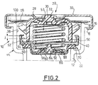
- Figures 1 and 2 show a plug pressure switch 10 which is designed for sealing a pipe 12 whose free end, upper in considering Figure 1, is constituted by a base 14 of standardized design.
- the base 14 has at its upper part a notched radial shoulder 16 which has ramps (not shown) which are intended to cooperate with a shoulder complementary internal radial 18 formed in the underside of the upper cover 20 of the plug 10.
- the base 14 has also, at its lower part, an annular seat, of section semicircular, 22 which constitutes a fixed annular seat of overpressure for the pressure switch 10.
- the plug 10 essentially consists of a body of the plastic plug 24.
- the body of the plug 24 has a general shape of a bell and thus comprises an annular cylindrical side skirt 26 and an upper wall 28 which ends in its center by a body of rivet 30 produced integrally by molding with the body of the plug 24 which connects the body of the plug 24 to the cover 20.
- the cover 20 which is a sheet metal part cut and folded, has a central hole 32 which is crossed by the body of the rivet 30 with a radial clearance so as to allow the rotatable mounting of the cover 20 on the body 24.
- the final link between the two elements is ensured by hot crimping of the head 34 of the rivet 20.
- the annular skirt 26 has, on its outer wall, a series of centering fins 36.
- the fins 36 are distributed angularly so regular around the axis X-X of the body of the plug 24 and of the plug 10, and they protrude radially outward to constitute the fins of the plug body 24 during its installation in the base 14 by cooperating with the internal cylindrical wall 38 of the base 14.
- the skirt ring 26 of the plug body 24 has a radial collar exterior 40 in which a series of notches 42 is produced distributed angularly in a regular way and which is used for retain the body of the plug on the body 24 pressure relief valve 44.
- the body of the pressure relief valve 44 is a sheet metal part cut and folded which has a general shape of a dish.
- the cup 44 has an annular cylindrical skirt 46 which is open at its upper part and whose upper edge free end 48 has a series of legs 50 which are cut and folded radially inward to cooperate with the upper face opposite 52 of the collar 40, and this under the action of an overpressure calibration spring 53 arranged at inside the cap body 24.
- the skirt 46 of the cup 44 extends at its lower edge by an annular connecting portion 54 in the form of a flat disc which extends in a plane perpendicular to the X-X axis.
- the cup 44 includes a blind bottom 56 in the form of a bowl comprising a skirt slightly conical annular 58 whose average diameter is significantly lower than that of the skirt 46.
- the bottom 56 has a raised flat part 60 which thus delimits an annular housing 62 in the bottom of the cup 56 which serves to support one end 64 of the spring of calibration 53 while the opposite end 66 of the latter takes support against an annular surface 68 formed opposite in the upper wall 28 of the plug body 24.
- the lower face or external face of the cup 44 is coated with a sealing membrane 70 of elastomeric material which constitutes the waterproofing membrane of the pressure relief valve and which, in the closed position and as illustrated on the FIG. 2 cooperates tightly with the seat 22.
- the active part of the overpressure waterproofing membrane consists of the underside 72 of its annular part which bears against the connecting part 54.
- This active part is extended by a thinner layer 74 which follows the external profile of the bowl 58 and which is pierced in its center 76, like the raised part 60 of the bottom of the bowl 56 in 77, to allow passage to the central foot 78 of the pressure relief valve body 80.
- the body of the pressure relief valve 80 is constituted for essentially by a disc 82 which, in the closed position and as this is illustrated in the figures, sealing off the holes 76 and 77 supported by its upper face 84 against the facing part 86 of the sealing membrane.
- the sealed cooperation of the plate 82 with the part 86 of the membrane is provided by a compression spring 88 which takes support against an upper shoulder of the foot 78.
- the clearance "j" is such that when the operator puts the cap in placed on the base 14, the membrane 70 comes into contact with the annular seat 22 before the latching operation of the part lower 18 of the cover 20 with the ramps of the shoulder 16 so as to eliminate any parasitic friction between the legs 50 and the shoulder 40 during the locking operation by cap rotation.
- the realization of the plug body 24 molded in plastic material allows, thanks to the choice of different colors of the material molded plastic, to make a visual identification for the user of the taring value of the cap and thus avoid any error in the mounting of the cap.
- the elastic washer 98 eliminates the play existing between the different components and it can be coated, according to a variant not shown in the figures, a sealing membrane on its underside which cooperates with the rounded upper edge 100 of the base 14 in order to ensure sealing of the upper part of the base 14 which extends up to the annular overpressure seat 22.
- the design according to the invention thus makes it possible to reduce the differences usually found between the pressure of tripping of the pressure relief valve and the theoretical pressure resulting from the design of the latter which depends in particular on dimensional tolerances on the dimensions of the base 14 and different components of the plug 10.
Landscapes
- Engineering & Computer Science (AREA)
- Chemical & Material Sciences (AREA)
- Combustion & Propulsion (AREA)
- Mechanical Engineering (AREA)
- General Engineering & Computer Science (AREA)
- Closures For Containers (AREA)
- Quick-Acting Or Multi-Walled Pipe Joints (AREA)
- Connector Housings Or Holding Contact Members (AREA)
Claims (13)
- Druckregelnder Deckel (10) zum Verschließen einer Öffnung (12), die an ihrem freien Ende eine Sitzfläche (14) für die Verrastung des Deckels in Schließposition enthält, umfassend eine Überdruckklappe mit einem Überdruckklappenkörper (44), der im Verhältnis zum Körper (24) des Deckels (10) beweglich gelagert ist und der eine Überdruckdichtungsmembran (70) trägt, und eine Einstellfeder (53) für den Wert des Überdrucks, die in Schließposition des Deckels den Überdruckklappenkörper (44) und die Überdruckdichtungsmembran (70) in Anlage an einen ortsfesten ringförmigen Überdrucksitz (22) beaufschlagt, der in der Sitzfläche (14) der Öffnung (22) ausgebildet ist, wobei der Überdruckklappenkörper (44) im Verhältnis zum Deckelkörper (24) anhand von radialen Halteansätzen (50) gehalten wird, die sich gegenüber einer radialen Anschlagschulter (52) erstrecken, die am Deckelkörper (24) ausgebildet ist, wobei in Schließposition des Deckels ein axiales Spiel (j) zwischen den radialen Halteansätzen (50) und der radialen Anschlagschulter (52) besteht, dadurch gekennzeichnet, daß der Deckelkörper (24) ein glockenförmiges Formteil aus Kunststoff ist, dessen seitliche Einfassung (26) eine Reihe von Rippen (36) für die Zentrierung des Deckelkörpers (24) in der Sitzfläche (14) beim Einsetzen des Deckels (10) umfaßt.
- Druckregelnder Deckel nach Anspruch 1 , dadurch gekennzeichnet, daß die seitliche Einfassung (26) des Deckelkörpers (24) an ihrem unteren Ende einen äußeren radialen Bund (40) umfaßt, der die radiale Anschlagschulter (52) begrenzt.
- Druckregelnder Deckel nach Anspruch 1 , dadurch gekennzeichnet, daß sich die Rippen (36) in axialen Ebenen erstrecken.
- Druckregelnder Deckel nach einem der Ansprüche 1 bis 3, dadurch gekennzeichnet, daß der obere Teil (28) des glockenförmigen Deckelkörpers (24) einen Nietschaft (30, 32) umfaßt, der einstückig aus Kunststoff am Deckelkörper angeformt ist, um auf diesem die drehbare Lagerung einer Verschlußkappe (20) des Deckels zu (10) ermöglichen, die Mittel (18) zur Verrastung des Deckels auf der Sitzfläche (14) umfaßt.
- Druckregelnder Deckel nach Anspruch 4 , dadurch gekennzeichnet, daß zwischen dem oberen Teil (28) des Deckelkörpers (24) und der gegenüberliegenden Innenseite der Verschlußkappe (20) eine axiale Klemmfederscheibe (98) eingefügt ist.
- Druckregelnder Deckel nach einem der Ansprüche 1 bis 5, dadurch gekennzeichnet, daß der Deckelkörper (24) aus einem Kunststoff geformt ist, dessen Farbe den Einstellwert der Überdruckklappe angibt.
- Druckregelnder Deckel nach einem der vorangehenden Ansprüche , dadurch gekennzeichnet, daß der Körper der Überdruckklappe ein Blechteller (44) ist, der insbesondere eine seitliche Einfassung (46) aufweist, deren freie Oberkante (48) die Halteansätze (50) umfaßt und deren Innenseite eine ringförmige Auflagefläche (62) für ein Ende (64) einer Schraubendruckfeder (53) begrenzt, deren anderes Ende (66) am Deckelkörper (24) zur Einstellung der Überdruckklappe zur Anlage kommt.
- Druckregelnder Deckel nach Anspruch 7 , dadurch gekennzeichnet, daß der Teller (44) eine mittige Schale (56) umfaßt, die mit der seitlichen Einfassung durch eine ringförmige Anschlußzone (54) verbunden ist, die sich in einer diametralen Ebene erstreckt und die die Überdruckdichtungsmembran (70, 72) trägt.
- Druckregelnder Deckel nach Anspruch 8 , dadurch gekennzeichnet, daß das Ende (64) der Feder (54) am Boden (62) der Schale (56) des Tellers (44) zur Auflage kommt, der im Verhältnis zur ringförmigen Anschlußzone (54) axial versetzt ist, um die Anordnung einer Einstellfeder (53) mit großer Länge zu ermöglichen.
- Druckregelnder Deckel nach einem der vorangehenden Ansprüche, dadurch gekennzeichnet, daß er eine Unterdruckklappe, die einen beweglichen ringförmigen Unterdrucksitz (82) enthält, der auf einem Unterdruckklappenkörper (80) ausgebildet ist, der im Verhältnis zum Überdruckklappenkörper (44) beweglich gelagert ist, eine Unterdruckdichtungsmembran (86), die am Überdruckklappenkörper (44) angebracht ist, und eine Einstellfeder (88) für den Wert des Unterdrucks umfaßt, die den Sitz (82) des Überdruckklappenkörpers (80) in dichter Anlage an die Unterdruckdichtungsmembran beaufschlagt, und daß die Unterdruck- und Überdruckdichtungsmembranen in Form einer einzigen Dichtungsmembran (70) ausgeführt sind, die am Überdruckklappenkörper (44) angebracht ist.
- Druckregelnder Deckel nach Anspruch 10 in Kombination mit Anspruch 9 , dadurch gekennzeichnet, daß der Unterdruckklappenkörper in Form einer Platte (80) ausgeführt ist, deren Oberseite (82) einen mittigen Fuß (78) umfaßt, der durch den Boden (60) der Schale (56) des Tellers des Überdruckklappenkörpers (44) hindurchgeht, und daß die Unterdruckeinstellfeder (88) an der Innenseite des Bodens (60) der Schale (44) zur Anlage kommt.
- Druckregelnder Deckel nach Anspruch 11 , dadurch gekennzeichnet, daß sich die einzige Dichtungsmembran (70) an das äußere Profil der Schale (56) des Tellers (44) anpaßt.
- Druckregelnder Deckel nach einem der Ansprüche 11 oder 12, dadurch gekennzeichnet, daß die einzige Dichtungsmembran (70) aus Elastomermaterial durch Aufformen auf dem Teller (44) ausgeführt ist.
Applications Claiming Priority (2)
| Application Number | Priority Date | Filing Date | Title |
|---|---|---|---|
| FR9412140A FR2725491B1 (fr) | 1994-10-10 | 1994-10-10 | Bouchon pressostatique, notamment pour l'obturation d'une canalisation du circuit de refroidissement d'un vehicule automobile |
| FR9412140 | 1994-10-10 |
Publications (2)
| Publication Number | Publication Date |
|---|---|
| EP0706953A1 EP0706953A1 (de) | 1996-04-17 |
| EP0706953B1 true EP0706953B1 (de) | 1998-03-18 |
Family
ID=9467765
Family Applications (1)
| Application Number | Title | Priority Date | Filing Date |
|---|---|---|---|
| EP19950115617 Expired - Lifetime EP0706953B1 (de) | 1994-10-10 | 1995-10-04 | Druckregelnder Deckel, insbesondere zum Verschliessen einer Öffnung eines Kühlwasserkreislaufs eines Kraftfahrzeugs |
Country Status (4)
| Country | Link |
|---|---|
| EP (1) | EP0706953B1 (de) |
| DE (1) | DE69501813T2 (de) |
| ES (1) | ES2117343T3 (de) |
| FR (1) | FR2725491B1 (de) |
Families Citing this family (1)
| Publication number | Priority date | Publication date | Assignee | Title |
|---|---|---|---|---|
| DE19960590A1 (de) * | 1999-12-16 | 2001-07-05 | Messer Cutting & Welding Ag | PIN-index-Flaschenventil |
Family Cites Families (4)
| Publication number | Priority date | Publication date | Assignee | Title |
|---|---|---|---|---|
| US2164450A (en) * | 1937-12-30 | 1939-07-04 | Gen Motors Corp | Radiator pressure cap |
| US3053408A (en) * | 1960-09-08 | 1962-09-11 | Stant Mfg Company Inc | Radiator cap with safety gasket |
| US3587912A (en) * | 1968-08-23 | 1971-06-28 | Nippon Denso Co | Pressure cap unit with pressure releasing means for radiators of internal combustion engines |
| GB1237176A (en) * | 1969-06-05 | 1971-06-30 | Gen Motors Ltd | Closure caps |
-
1994
- 1994-10-10 FR FR9412140A patent/FR2725491B1/fr not_active Expired - Fee Related
-
1995
- 1995-10-04 DE DE1995601813 patent/DE69501813T2/de not_active Expired - Lifetime
- 1995-10-04 EP EP19950115617 patent/EP0706953B1/de not_active Expired - Lifetime
- 1995-10-04 ES ES95115617T patent/ES2117343T3/es not_active Expired - Lifetime
Also Published As
| Publication number | Publication date |
|---|---|
| DE69501813T2 (de) | 1998-07-09 |
| DE69501813D1 (de) | 1998-04-23 |
| FR2725491A1 (fr) | 1996-04-12 |
| ES2117343T3 (es) | 1998-08-01 |
| EP0706953A1 (de) | 1996-04-17 |
| FR2725491B1 (fr) | 1996-11-29 |
Similar Documents
| Publication | Publication Date | Title |
|---|---|---|
| FR2733467A1 (fr) | Ensemble a clapet pour reservoir de carburant | |
| FR2975882A1 (fr) | Soupape de securite pour appareil de cuisson sous pression et dispositif incluant une telle soupape | |
| WO1999011387A1 (fr) | Dispositif de distribution a bague de fixation a emmanchement conique | |
| EP2432707B1 (de) | Tropfschutzverschluss mit elastisch rückgeführter beweglicher abdeckung | |
| EP2216220B1 (de) | Schutzvorrichtung eines Bremsflüssigkeitsbehälters, und mit solchen Vorrichtungen ausgestatteter Behälter | |
| EP2139605B1 (de) | Pumpe zur verteilung eines flüssigprodukts und spender mit einer solchen pumpe | |
| EP1042593B1 (de) | Verschlussvorrichtung für öleinfüllöffnung | |
| EP0706953B1 (de) | Druckregelnder Deckel, insbesondere zum Verschliessen einer Öffnung eines Kühlwasserkreislaufs eines Kraftfahrzeugs | |
| FR2845357A1 (fr) | Dispositif de fixation et distributeur comprenant un tel dispositif de fixation | |
| EP3416748B1 (de) | Ausgabeelement und spender mit solch einem element | |
| EP0064427B1 (de) | Druckregulierventil | |
| EP0345102A1 (de) | Behälterverschlusskappe | |
| EP1174650B1 (de) | Sicherheitsventil für einen in der Chemischen-/ Nahrungsmittelindustrie genutzten Behälter | |
| EP0908809B1 (de) | Umgossener Ventilkörper insbesondere für ein Thermostatventil und Thermostatventil damit | |
| EP0518717B1 (de) | Kühlerverschlussdeckel für Kraftfahrzeuge | |
| EP0015187B1 (de) | Verschluss für Kohlenwasserstoff- oder ähnlichen Flüssigkeits behälter | |
| FR2711586A1 (fr) | Bouchon pour la fermeture de la canalisation de remplissage d'un réservoir de carburant de véhicule automobile. | |
| FR2766134A1 (fr) | Dispositif de mise a l'air libre et de securite pour un reservoir de carburant de vehicule automobile | |
| FR2720469A1 (fr) | Bouchon comportant des clapets de dépression et de surpression. | |
| EP0116796B1 (de) | Diebessichere Kappe, insbesondere für Brennstofftanks von Fahrzeugen | |
| FR2725490A3 (fr) | Clapet etanche et bouchon pressostatique comportant au moins un tel clapet | |
| FR2466433A1 (fr) | Bec d'emplissage | |
| FR2779496A1 (fr) | Dispositif de commande hydraulique d'un embrayage, notamment pour vehicule automobile | |
| FR1450460A (fr) | Bouchon, en particulier pour circuit de refroidissement de moteur | |
| FR2741133A1 (fr) | Bouchon perfectionne pour un circuit de refroidissement de vehicule automobile |
Legal Events
| Date | Code | Title | Description |
|---|---|---|---|
| PUAI | Public reference made under article 153(3) epc to a published international application that has entered the european phase |
Free format text: ORIGINAL CODE: 0009012 |
|
| AK | Designated contracting states |
Kind code of ref document: A1 Designated state(s): DE ES GB IT |
|
| 17P | Request for examination filed |
Effective date: 19960926 |
|
| GRAG | Despatch of communication of intention to grant |
Free format text: ORIGINAL CODE: EPIDOS AGRA |
|
| GRAG | Despatch of communication of intention to grant |
Free format text: ORIGINAL CODE: EPIDOS AGRA |
|
| GRAH | Despatch of communication of intention to grant a patent |
Free format text: ORIGINAL CODE: EPIDOS IGRA |
|
| 17Q | First examination report despatched |
Effective date: 19970903 |
|
| GRAH | Despatch of communication of intention to grant a patent |
Free format text: ORIGINAL CODE: EPIDOS IGRA |
|
| GRAA | (expected) grant |
Free format text: ORIGINAL CODE: 0009210 |
|
| AK | Designated contracting states |
Kind code of ref document: B1 Designated state(s): DE ES GB IT |
|
| GBT | Gb: translation of ep patent filed (gb section 77(6)(a)/1977) |
Effective date: 19980319 |
|
| REF | Corresponds to: |
Ref document number: 69501813 Country of ref document: DE Date of ref document: 19980423 |
|
| ITF | It: translation for a ep patent filed | ||
| REG | Reference to a national code |
Ref country code: ES Ref legal event code: FG2A Ref document number: 2117343 Country of ref document: ES Kind code of ref document: T3 |
|
| PLBE | No opposition filed within time limit |
Free format text: ORIGINAL CODE: 0009261 |
|
| STAA | Information on the status of an ep patent application or granted ep patent |
Free format text: STATUS: NO OPPOSITION FILED WITHIN TIME LIMIT |
|
| 26N | No opposition filed | ||
| REG | Reference to a national code |
Ref country code: GB Ref legal event code: IF02 |
|
| PGFP | Annual fee paid to national office [announced via postgrant information from national office to epo] |
Ref country code: DE Payment date: 20101027 Year of fee payment: 16 |
|
| PGFP | Annual fee paid to national office [announced via postgrant information from national office to epo] |
Ref country code: GB Payment date: 20101025 Year of fee payment: 16 Ref country code: IT Payment date: 20101028 Year of fee payment: 16 |
|
| PGFP | Annual fee paid to national office [announced via postgrant information from national office to epo] |
Ref country code: ES Payment date: 20101026 Year of fee payment: 16 |
|
| GBPC | Gb: european patent ceased through non-payment of renewal fee |
Effective date: 20111004 |
|
| PG25 | Lapsed in a contracting state [announced via postgrant information from national office to epo] |
Ref country code: DE Free format text: LAPSE BECAUSE OF NON-PAYMENT OF DUE FEES Effective date: 20120501 |
|
| REG | Reference to a national code |
Ref country code: DE Ref legal event code: R119 Ref document number: 69501813 Country of ref document: DE Effective date: 20120501 |
|
| PG25 | Lapsed in a contracting state [announced via postgrant information from national office to epo] |
Ref country code: GB Free format text: LAPSE BECAUSE OF NON-PAYMENT OF DUE FEES Effective date: 20111004 Ref country code: IT Free format text: LAPSE BECAUSE OF NON-PAYMENT OF DUE FEES Effective date: 20111004 |
|
| REG | Reference to a national code |
Ref country code: ES Ref legal event code: FD2A Effective date: 20130605 |
|
| PG25 | Lapsed in a contracting state [announced via postgrant information from national office to epo] |
Ref country code: ES Free format text: LAPSE BECAUSE OF NON-PAYMENT OF DUE FEES Effective date: 20111005 |