EP0706920A1 - Système de sécurité - Google Patents
Système de sécurité Download PDFInfo
- Publication number
- EP0706920A1 EP0706920A1 EP95203205A EP95203205A EP0706920A1 EP 0706920 A1 EP0706920 A1 EP 0706920A1 EP 95203205 A EP95203205 A EP 95203205A EP 95203205 A EP95203205 A EP 95203205A EP 0706920 A1 EP0706920 A1 EP 0706920A1
- Authority
- EP
- European Patent Office
- Prior art keywords
- electrical
- key
- vehicle
- circuitry
- engine
- Prior art date
- Legal status (The legal status is an assumption and is not a legal conclusion. Google has not performed a legal analysis and makes no representation as to the accuracy of the status listed.)
- Withdrawn
Links
Images


Classifications
-
- B—PERFORMING OPERATIONS; TRANSPORTING
- B60—VEHICLES IN GENERAL
- B60R—VEHICLES, VEHICLE FITTINGS, OR VEHICLE PARTS, NOT OTHERWISE PROVIDED FOR
- B60R25/00—Fittings or systems for preventing or indicating unauthorised use or theft of vehicles
- B60R25/01—Fittings or systems for preventing or indicating unauthorised use or theft of vehicles operating on vehicle systems or fittings, e.g. on doors, seats or windscreens
- B60R25/04—Fittings or systems for preventing or indicating unauthorised use or theft of vehicles operating on vehicle systems or fittings, e.g. on doors, seats or windscreens operating on the propulsion system, e.g. engine or drive motor
Definitions
- This invention relates to a security system.
- US3714628 discloses a security system which, when applied to a vehicle, or other instrumentality, is intended to prevent unauthorized use of the vehicle or other device on which it is installed, and to prevent tampering with any component attached to the vehicle or device.
- the conventional cylinder and tumbler locks are omitted and replaced with a multiple contact plug and socket.
- the plug is associated with a special key unit, coded and matched with a special lock unit associated with the socket, itself associated with a door and/or with an ignition unit.
- the owner may lock and unlock the doors and/or boot, start and drive the vehicle, and turn off the ignition, in much the same way as he would use the conventional key.
- the system is so constructed as to turn off all the major components, including the ignition, petroleum supply, and electrical current to the various components.
- the system also includes setting an alarm against motion and unauthorized entry.
- a serious drawback of the system is that a thief can probe the terminals in its socket with a multimeter to determine which leads are performing which functions in the electrical system of the vehicle, and then connect across the relevant terminals.
- GB2136620 discloses a security system to prevent unauthorised use of a motor vehicle or other device, the system comprising a crystal oscillator circuit with a crystal which is removable for keeping by an authorised user, the crystal defining the frequency of oscillation of the oscillator circuit, a filter circuit tuned to the frequency of the oscillator circuit, and some means disabling the device against operation except upon receipt of a signal from the oscillator circuit via the tuned filter circuit when the crystal is inserted in the oscillator circuit.
- the disabling means includes a relay having three changeover switches, of which one is employed for internal latching, the second is employed to maintain a bonnet lock solenoid energized in the absence of the crystal and the third is employed to cut the power to the ignition coil and instead applies it to the horn for alarm purposes, until the key is inserted, whereupon the power is transferred to the ignition coil.
- the system interrupts the power supply to only one device essential to the starting of the engine, namely the ignition coil at its positive side, so that the engine can be relatively easily jump-started by running a jump lead from the battery positive terminal to the ignition coil positive terminal.
- the horn would be sounded upon such jump-starting, a thief would simply sever the power supply to the horn. Therefore the only happening which would alert, for example, a policeman to the fact that the vehicle was being stolen would be the horn sounding and this could be for only a very short time.
- US4278963 discloses a system similar to that of GB2136620 except that the secure control means consists of an additional mechanical key and a combination thumbwheel switch arrangement and that, instead of interrupting the power supply to the ignition coil, it interrupts the supply to the starter solenoid.
- US4546266 describes a security system in which an electrical circuit, the starting circuit for a motor vehicle for example, is selectively enabled by a control circuit which includes a magnetic field responsive switching device. Proper positioning of a magnet which provides a field of the appropriate polarity and strength relative to the switching device results in the energization of a relay which has contacts connected in series with the circuit being controlled. In the motor vehicle application, operation of the ignition switch within a pre-determined time subsequent to removal of the magnet will latch the relay in the energized state.
- the system is relatively insecure in that a thief either arrives provided with another suitable magnet or traces the wiring to the magnetically operated switching device and bypasses the device, and in that it interrupts the power supply to the starter relay, so that the vehicle can be push-started.
- Another security weakness is the utilization of a "service" plug, thus increasing the opportunities open to a potential thief.
- a vehicle security system comprising principal electrical circuitry which can be completed electrically by use of secure control means thereby to render said principal electrical circuitry ineffective as security, secondary electrical circuitry, an accessory, e.g. a vehicle horn, electrically connected to said secondary electrical circuitry for operation thereby, and relay means between said principal electrical circuitry and said secondary electrical circuitry and operable upon completion of said principal electrical circuitry to close said secondary electrical circuitry, characterized in that a plurality of accessories selected from windscreen wiper motors, exterior lamps and a horn are electrically connected to said relay means by way of said secondary electrical circuitry.
- the principal electrical circuitry may comprise electrical control circuitry, and the system may further comprise a plurality of electrical devices connectible to said control circuitry for operation thereby, and electrical conductors, at least one being included in said control circuitry and extending to an interruption location where said conductors terminate and others extending from said interruption location to said electrical devices, the secure control means being usable at said location to connect said at least one to said others individually, and one or more further electrical conductors having no operating function being arranged among at least some of the first-mentioned conductors in the manner of a wiring loom.
- At least one of the first-mentioned conductors may have a discontinuity therein, and tapped-in conductors be connected to respective opposite sides of the discontinuity and arranged among at least some of the first-mentioned conductors in the manner of a wiring loom.
- a security system comprising electrical control circuitry including relay means including a plurality of individual switching means openable and closable by energization of said relay means, and a plurality of electrical devices connectible to said individual switching means, characterized in that any one of said plurality of electrical devices is operatively connectible to any one of said individual switching means.
- the arrangement whereby any one of the devices is operatively connectible to any one of the switching means increases the number of security permutations available compared with an arrangement whereby each switching means is dedicated to a particular device.
- the present system has a wide variety of fields of application, but is particularly applicable to motor vehicles.
- a vehicle security system comprising an electronic device for controlling an engine, sensing means for sensing states of said engine, and conductor means extending between said sensing means and said electronic device, characterized in that said conductor means extends between said sensing means and said electronic device by way of an interruption location, and in that secure control means is usable at said location to enable said sensing means to transmit signals to said electronic device by way of said conductor means.
- the secure control means can take various forms but is advantageously an electrical or electronic key.
- the present invention it is possible to provide an anti-theft device for a vehicle, the electrical circuits of which device cannot be by-passed from within the driving compartment of the vehicle. Moreover, it would be extremely difficult for a potential thief to start the engine from within the engine compartment, without effectively re-wiring, for which activity there would normally not be sufficient time. The device therefore provides a very effective deterrent against vehicle theft.
- the device may comprise a series of linked electromagnetic relays or solid state on/off switching devices, with contacts whose arrangement may be varied, contained within a suitable housing and arranged such that, in the absence of electrical power, they are either in normally 'open' or normally 'closed' conditions.
- the housing may be integral with the dashboard or control panel of the vehicle or attached at any convenient point within the driving compartment or behind the dashboard or control panel.
- the relays can only be activated or caused to change their mode from 'open' to 'closed' and vice versa when the electrical link circuit among them is completed by the insertion of a coded electrical key, particularly a coded electronic key.
- the sequence of the electrical circuits in the anti-theft device may be varied from anti-theft device to anti-theft device to provide variations in type.
- the key may be flat and with one end formed in the plane of the key so as to provide various coded configurations to give further security in that a particular key configuration will only fit into a matching housing.
- the key may also have an aperture or series of apertures which can be positioned in any part of its plan area to provide a further, vertical coded configuration which will allow a light beam to pass through it or them from, for example, a light emitting diode to a light dependent resistor to further complete the electrical circuit .
- the key can be male in form and designed to be inserted into a female housing which has matching configurations in both its plane and a plane perpendicular thereto. When the housing is provided with electrical power via the insertion of the key, then the circuit is completed through the light emitting diode, the light dependent resistor and the additional contacts in the plane of the key provided that they match exactly.
- the electrical circuit thus completed by the key then transmits power to the electro-magnetic relays or solid state on/off switching devices contained within the housing and causes them to open or close to perform their prescribed function of supplying continuous electrical power to the various components of the engine to cause ignition to take place and the engine to function and continue to do so.
- the power needed to start the engine of a vehicle is provided by the vehicle ignition key being inserted into the ignition lock of the vehicle and turned to the 'on' or 'contact' position for it to start.
- the normal ignition system is interrupted by the electro-magnetic relays or solid state on/off switching devices contained within the anti-theft housing and, until such time that the anti-theft key is inserted, the circuit will not be completed and the engine will not start.
- the electrical power needed to complete the circuit and activate the light emitting diode and the light dependent receiver can be provided automatically from the battery of the vehicle and when the key is inserted the circuit is completed.
- the power thus provided could, for example, cause a solenoid or similar electrically powered locking mechanism to be activated and provide a means of being able to open or close the door of a vehicle and secure it in such manner that it would not be possible to open it without the key, other than by force. Substantial additional security can thereby be provided.
- All of the electrical connections to the vehicle components in question such as the ignition coil, the distributor and the fuel valve, in the case of a petrol internal combustion engine, may be contained within a ribbon of wires, sealed at the terminal ends within the housing, and the sequence of wires as they connect to the various components may be varied from anti-theft device to anti-theft device and the connections to and from the various components of the engine may be made by soldering them within the ribbon so as to make them virtually undetectable and taped up to simulate the original loom.
- the electrical connection carrying the ignition switch current to the positive side of the ignition coil passes through both the housing and the key of the anti-theft device.
- the housing and the key are arranged to carry the following main connections to other vital components which have to be electrically powered for the engine to start and to continue to run:-
- the system is designed to have its housing installed in the driving compartment of the vehicle or other convenient location of the vehicle and either fitted as an 'add-on' or incorporated as part of the original wiring loom when the vehicle is built.
- the wires extending from the housing to the vital components can be connected to the components with the variations being incorporated within the housing, instead of within the ribbon.
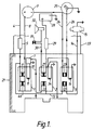
- a wire 4 carries the current from the ignition switch (not shown) through an in-line fuse 5 to normally closed contacts 6 of an electro-magnetic relay which is linked to an electronic timer module 7 through normally closed contacts 22 of an electro-magnetic relay 2 and through an electrical conductor 10.
- the current from the wire 4 passes through both sets 6 and 46 of normally closed contacts of the relay 1 (which are connected in parallel) through a wire connection 8 to the positive switch terminal of an ignition coil 9.
- the contacts 6 are normally closed when the ignition current is switched off but, with the ignition in the 'on' or 'contact' condition, they are caused to open after an adjustable pre-set delay time because the ignition current is also simultaneously connected through the normally closed contacts 22, thereby transmitting power to the electronic timer module 7 which, after the time delay, will energise the solenoid 11 of the relay 1, thus causing the closed contacts 6 and 46 to open.
- ignition current is simultaneously connected to one set of normally open contacts 12 of a relay 3, via a connection 13.
- normally open contacts are connected by a wire 14 to a fuel flow inhibiting valve 15, which may be of any suitable type, which valve will be caused to open and supply fuel when electrically energised.
- a fuel flow inhibiting valve 15 which may be of any suitable type, which valve will be caused to open and supply fuel when electrically energised.
- electrical power will not be transmitted to the valve 15 and, again, the engine will not run.
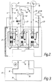
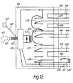
- Figure 2 shows the states of the relays 1 to 3 after the ignition has been switched to 'on' or 'contact' and immediately after the timer module has energised the solenoid 11, thus opening the contacts 6 and 46, and in the absence of the key portion 17 shown in Figure 3.
- Figure 3 illustrates, in plan, a simplified example of the key portion 17 including a circuit part 18 which incorporates a resistor 35 and which may incorporate a light emitting diode 36 to give a visual indication that a circuit through the part 18 has been completed when the portion 17 has been inserted into the main portion 21.
- the key portion 17 includes coded configurations 19 formed in its end intended to be inserted and also an aperture 20 which will allow a light beam to pass through it from a light source in the form of a light emitting diode to a light dependent resistor (both of which are not shown but may be incorporated within the main portion 21).
- Figure 4 illustrates in plan the key portion 17 in position within the main portion 21.
- a wire 24 extends from the negative terminal of the coil 9 to the contacts 23 and a wire 26 extends from the contacts 23 to a distributor 25 . Again, in the absence of the key portion 17 to complete the circuit and thus without power to close the contacts of the relay 3, these contacts will remain open, thus preventing power supply to the distributor 9.
- a second set of normally closed contacts 27 to complete a circuit from the positive terminal of a battery 28 via a wire 40, an in-line fuse 29 and a wire 30 to (for example) a bonnet tilt switch 31 and thence to an electric horn 32, or other audible alarm device which may be fitted to the vehicle.
- the ribbon is preferably flat in section and arranged such that the wires selected from within it which connect to the various components can be varied from anti-theft device to anti-theft device to provide further security within the system, in that it would not be readily apparent where the connections terminated or which were connected to the various relays within the housing.
- the ribbon 33 is arranged such that all of the terminals are sealed within the housing so that access cannot be gained to them other than by cutting through them, which action would blow the security fuses provided and thereby prevent an excessive heat build-up through the system having been short circuited. Such an act would, in any event, immobilise the vehicle completely.
- connections which are made to and from the various components of the engine would be made within the length of the ribbon 33 and, once properly soldered, the whole would be formed into a tube and wrapped around the normal wiring loom of the vehicle or incorporated within it and overtaped with insulating material in such manner as to be totally concealed.
- Any one of the wires which is not employed within the ribbon can be used as an earthing wire or several of them can be joined together for the same purpose.
- Figures 5 and 6 disclose a version in which such components are omitted from the anti-theft device and instead the hidden complication of the wiring is more heavily relied upon to give the required security.
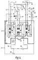
- Figure 5 shows the wires and connections which either are part of the loom where fitted as original equipment to a vehicle or are added to an existing loom.
- the lines 101 to 115 and 101' to 115' denote the wires or connections - including earthing and unused wires - which extend from or are attached to the main portion 116 of the anti-theft device and the key portion 117.
- the portion 117 houses a resistor 118 and a light emitting diode 119 connected in series with each other, but not in series with the ignition coil 124, the distributor 125, an electronic module or engine management system 126, the battery 127, the sonic alarm device 128 and the fuel valve 129, so that failure of the component 118 or 119 does not affect operation of these other items.
- the portion 117 further includes a resistor 120, a rechargeable battery 121 and a miniature lens bulb 122 again connected in series with each other but not with those other items.
- An in-line fuse 123 is provided within the system to protect the vehicle against fire in the event that the system is 'short-circuited' inadvertently by a potential thief trying to break into it and contacting the wrong connections.
- the small circles numbered 131 to 139 indicate random soldering or joining points for the wires where they are to be joined to those in an existing loom and the numbers 140, 141, 142 and 143 indicate further earthing points for various components.
- the positive terminal of the ignition coil 124 is connected via the wire 106 to the ignition switch wire 102 and the valve 129 through the wire 114.
- the negative terminal of the ignition coil 124 is, in turn, connected via the wires 104 and 108 to the distributor 125.
- the distributor 125 is, in turn, connected via the wires 105 and 107 to the electronic module or engine management system 126.
- the battery 127 is connected via the wires 111 and 113 to a tilt switch 130 which activates the sonic alarm device 128.
- the wires 101, 103, 109, 110, 112 and 115 represent earthing or 'unused' wires which can be used to expand the system further if so desired but in any event are provided as surplus to actual requirements to allow a high degree of random selection to be built into the system and by so doing provide for the maximum possible number of variations.
- this arrangement provides a high degree of security against theft of a vehicle and, in the absence of the key 117, it would be virtually impossible to break into the system and link all of the interdependent connections in the correct sequence to cause ignition to take place and for the engine to work.
- Figure 6 shows the same arrangement of components of the engine but connected in a different wiring sequence to the housing 116 and thence to the key 117 and serves to illustrate how the system can be varied so as to provide additional security through variations in the installation sequence and allocation of connections.
- the coil 124 is connected to the wires 107 and 108, the distributor 125 to the wires 107 and 109, the module or system 126 to the wire 110, the battery 127 to the wire 111, the switch 130 to the wire 113, the valve 129 to the wire 112, and the wires 102, 103, 105, 106, 114 and 115 to earth.
- the key portion 217 is insertable into a socket 252 from which flying leads 253 in a wiring ribbon extend into a main portion 216.
- a coil 254 and four contact sets 255 to 258 of a four-pole changeover relay are connected to the output of the amplifier 250 for energization in response to an output signal from the circuitry 251 in the event that the correct key portion 217 is inserted and the ignition key switched on.
- the contact sets 255, 256 and 257 are normally open and the contact set 258 is normally closed.
- a wire 259 from the positive terminal of the battery is directly connected to the amplifier 250 for energization of a sound warning device 260 in the event that the key portion 217 is left in the socket 252 when the ignition is switched off. This is intended to remind the driver to take his key portion 217 with him.
- the ignition switch wire 204 is also connected to the amplifier 250.
- the positive terminal of the battery is also connected through a wire 262 containing the mercury tilt switch 231 and the siren 232 to the normally closed contact set 258 and thence to the wire 261.
- Two earthed dud wires 263 and 264 are interposed between the wires 261 and 262.
- Two wires 265 and 266 are connected to the normally open contact set 257 and can be connected across a cut wire between the distributor and an electronic ignition module (if provided).
- the normally open contact set 256 is connected to wires 267 and 268 connected to the distributor points and the contact breaker terminal of the ignition coil, with two earthed dud wires 269 and 270 being located between them.
- the normally open set 255 connects the wire 204 to three wires 271 to 273.
- the wire 271 is connected to the switch terminal of the ignition coil; the wire 272 to the power line to the electrical fuel pump (if provided) or (if not) to the solenoid-operated fuel cut-off valve; and the wire 273 to ignition-controlled accessories, such as wiper motors.
- the resistors in the key 217 may be four in number and may be identical to, or different from, each other in value.
- the four resistors in the key must match four resistors provided in the digital comparator in the circuitry 251. Since resistors can vary in value between zero ohms and several million ohms, hundreds of thousands of combinations are available.
- sequence of entry of the flying leads 253 into the resin-pot housing 216 can be varied from device-to-device, as can the sequence of entry of the wires 204 and 261-273 into that housing.
- the items 304, 316, 317, and 352 to 373 correspond respectively to the items 204, 216, 217, and 252 to 273 in the version of Figure 7.
- An extra wire 374 is provided serving a similar purpose to that of the line 273.
- the item 375 is a hybrid chip which effectively performs the functions of the amplifier 250 and the circuitry 251 in Figure 7.
- the motor vehicle 376 has a bonnet 377 liftable to give access to an engine compartment containing a spark-ignition, petrol, internal combustion engine 378.
- a steering wheel 379 Within the passenger compartment are seen a steering wheel 379, an electronic key portion 317 and its associated socket 352, a sound warning device 360 and a light emitting diode (LED) device 380 which is connected in the wire 362 and which indicates that the anti-theft device is effective.
- the device 380 is provided because otherwise there is nothing to enable a user to distinguish between the effective condition of the anti-theft device and a condition where there is no power supply available, for example because of a faulty connection to the battery 328 in the engine compartment.
- the engine compartment may also contain the main portion 316 connected by flying leads 353 to the socket 352.
- the device 360 is connected by leads 381 to the main portion 316.
- a wire 383 extends from the positive terminal of the battery 328 to an ignition switch 384 closable by insertion and turning of an ignition key 385.
- a wire 386 leads from the switch 384 towards the positive terminal of an ignition coil 309 in the engine compartment.
- the wire 386 is interrupted at 387 and the wires 304 and 371 are tapped into the wire 386 at respective opposite sides of the interruption 387. Tapped into the wire 386 at a location between the switch 384 and the interruption 387 is a wire 388 leading towards an electronic ignition module 382 in the engine compartment.
- this wire is interrupted at 389 and the wires 365 and 366 are tapped into the wire 388 at respective opposite sides of this interruption 389.
- a wire 390 leads from the module 382 towards the negative terminal of the coil 309, but is interrupted at 391 and the two wires 367 and 368 are tapped into the wire 390 at respective opposite sides of the interruption 391.
- a fuel flow inhibiting valve 315 is connected between earth and the wire 372.
- a mercury tilt switch 331 and a siren 332 and the device 380 are connected between earth and the wire 362.
- a plurality of relay coils such as 392 and 393 are connected between earth and the wire 373 and serve to operate respective relay switches, such as 394 and 395, interposed in the supply lines, such as 396 and 397, of accessories unrelated to the anti-theft purpose, such as the headlamps 398. Extra “dud” wires 399 to earth are provided.
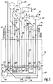
- FIG. 11 shows a cross-section through such a loom at a location where there are twenty-one wires, each wire consisting of its conductor encased in a plastics or rubber sheath for electrical insulation purposes, the bundle of wires being encased in an outer sheath 400 which may consist of insulating tape wrapped around the bundle.
- the items 404, 416, 417, 452 to 464, 469, 473 and 499 correspond to the respective items 304, 316, 317, 352 to 364, 369, 373 and 399 in Figure 9.
- the wire 471 is utilised to operate a solenoid valve controlling the supply of Diesel fuel to the engine, and the wire 467 is used to power heaters and injector units.
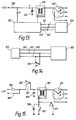
- FIG. 13 in addition to the ignition coil 309, the distributor 325 and the electronic ignition module 382, there are shown an electronic sensor 500 connected by conductors 501, 502 and 503 to the module 382 for transmitting to the module 382 information signals as to states of the engine 378, and a suppressive capacitor 504.
- the Figure illustrates diagrammatically at A, B and C, respectively, that the input of the module 382, the input of the coil 309, and/or at least one of the conductors 501 to 503 can be formed with one or more interruptions, i.e. discontinuities, at which can be tapped-in pairs of conductors connected to one or more relay contact sets at the main portion 316.
- the sensor 500 is a crank angle sensor and the earth and negative conductors 502 and 503 are short-circuited by way of a relay contact set 505 at the main portion 316 until the key 317 is inserted.
- the modification shown in Figure 15 relates to a conventional ignition, with the coil 309, the distributor 325, the suppressive capacitor 504, a ballast resistor 506, an earthed circuit breaker 507 and an earthed breaker capacitor 508.
- the negative side of the coil 309 at a location between the breaker circuit and the coil, is connected to earth by way of a relay contact set 509 at the main portion 316, until the key 317 is inserted. In this way, any thief connecting a jump lead between the battery and coil positive terminals will short the battery to earth and may burn out the jump lead.
- electromechanical relays illustrated in the various Figures can of course be replaced by electronic relays.
- the driver being required to carry at least two keys, namely the electrical key 17, 117, 217, 317, or 417, and the mechanical door and/or ignition key(s)
- the electrical key and the mechanical key may be combined into one key capable of "unlocking" both mechanically and electrically.
- the present device is also applicable, additionally or alternatively to preventing engine-starting, to other security purposes, for example to holding a vehicle or other door closed and to holding a wireless or a cassette player in its mounting aperture in a vehicle.
- Figure 8 illustrates a wireless 300 received in its mounting aperture in a dashboard 301 of a vehicle, between firmly fixed metal mounting plates 302.
- the wireless 300 has firmly incorporated therein respective solenoids 303 the armatures 303' of which are engaged in respective blind bores in the plates 302.
- the coils of the solenoids 303 are energisable following insertion of the correct electrical key and switching-on of the ignition, to withdraw the armatures 303' to allow removal of the wireless from its mounting aperture.
- This arrangement has the advantages that the wireless can be installed virtually as easily as is conventionally the case and yet a thief has a very great problem in removing the wireless without significantly damaging it and thus making it unsaleable.
Applications Claiming Priority (5)
| Application Number | Priority Date | Filing Date | Title |
|---|---|---|---|
| GB888808764A GB8808764D0 (en) | 1988-04-14 | 1988-04-14 | Security anti/theft device for vehicles |
| GB8808764 | 1988-04-14 | ||
| GB8813722 | 1988-06-09 | ||
| GB888813722A GB8813722D0 (en) | 1988-04-14 | 1988-06-09 | Electrical apparatus |
| EP89904827A EP0415947A1 (fr) | 1988-04-14 | 1989-04-11 | Systeme de securite |
Related Parent Applications (1)
| Application Number | Title | Priority Date | Filing Date |
|---|---|---|---|
| EP89904827.6 Division | 1989-04-11 |
Publications (1)
| Publication Number | Publication Date |
|---|---|
| EP0706920A1 true EP0706920A1 (fr) | 1996-04-17 |
Family
ID=10635150
Family Applications (1)
| Application Number | Title | Priority Date | Filing Date |
|---|---|---|---|
| EP95203205A Withdrawn EP0706920A1 (fr) | 1988-04-14 | 1989-04-11 | Système de sécurité |
Country Status (3)
| Country | Link |
|---|---|
| EP (1) | EP0706920A1 (fr) |
| GB (2) | GB8808764D0 (fr) |
| ZA (1) | ZA892763B (fr) |
Citations (9)
| Publication number | Priority date | Publication date | Assignee | Title |
|---|---|---|---|---|
| US3004170A (en) * | 1958-12-24 | 1961-10-10 | Greenspan Arnold | Automobile theft protection device |
| US3714628A (en) | 1971-11-03 | 1973-01-30 | T Sloger | Vehicle electrical locking and alarm system |
| US3756341A (en) * | 1971-07-22 | 1973-09-04 | Safetech Inc | Vehicle anti-theft system |
| US4278963A (en) | 1978-12-04 | 1981-07-14 | Luther Allen | Automotive anti-theft system |
| DE3241071A1 (de) * | 1982-11-06 | 1984-02-09 | Georg 8201 Eggstätt Hilger | Kombinationszuendschloss auch fuer motorradmaschinen |
| US4449605A (en) * | 1981-03-23 | 1984-05-22 | Read William A | Device for preventing theft of motor vehicles |
| GB2136620A (en) | 1983-03-02 | 1984-09-19 | Bernard John Ballantine | A security system |
| US4546266A (en) | 1983-07-28 | 1985-10-08 | Zenick Walter N | Magnetically actuated interlock |
| DE3620297C1 (de) * | 1986-06-16 | 1987-09-24 | Helmut Hirtz | Diebstahlsicherung fuer Kraftfahrzeuge mit elektronischen Motorsteuergeraeten |
-
1988
- 1988-04-14 GB GB888808764A patent/GB8808764D0/en active Pending
- 1988-06-09 GB GB888813722A patent/GB8813722D0/en active Pending
-
1989
- 1989-04-11 EP EP95203205A patent/EP0706920A1/fr not_active Withdrawn
- 1989-04-14 ZA ZA892763A patent/ZA892763B/xx unknown
Patent Citations (9)
| Publication number | Priority date | Publication date | Assignee | Title |
|---|---|---|---|---|
| US3004170A (en) * | 1958-12-24 | 1961-10-10 | Greenspan Arnold | Automobile theft protection device |
| US3756341A (en) * | 1971-07-22 | 1973-09-04 | Safetech Inc | Vehicle anti-theft system |
| US3714628A (en) | 1971-11-03 | 1973-01-30 | T Sloger | Vehicle electrical locking and alarm system |
| US4278963A (en) | 1978-12-04 | 1981-07-14 | Luther Allen | Automotive anti-theft system |
| US4449605A (en) * | 1981-03-23 | 1984-05-22 | Read William A | Device for preventing theft of motor vehicles |
| DE3241071A1 (de) * | 1982-11-06 | 1984-02-09 | Georg 8201 Eggstätt Hilger | Kombinationszuendschloss auch fuer motorradmaschinen |
| GB2136620A (en) | 1983-03-02 | 1984-09-19 | Bernard John Ballantine | A security system |
| US4546266A (en) | 1983-07-28 | 1985-10-08 | Zenick Walter N | Magnetically actuated interlock |
| DE3620297C1 (de) * | 1986-06-16 | 1987-09-24 | Helmut Hirtz | Diebstahlsicherung fuer Kraftfahrzeuge mit elektronischen Motorsteuergeraeten |
Also Published As
| Publication number | Publication date |
|---|---|
| ZA892763B (en) | 1989-12-27 |
| GB8808764D0 (en) | 1988-05-18 |
| GB8813722D0 (en) | 1988-07-13 |
Similar Documents
| Publication | Publication Date | Title |
|---|---|---|
| US5133426A (en) | Security system | |
| US4546266A (en) | Magnetically actuated interlock | |
| US4327353A (en) | Security system | |
| EP0682608B1 (fr) | Systeme de securite de vehicule | |
| US4866422A (en) | Security alarm system | |
| US5594284A (en) | Vehicle security device using key device which completes interrupted circuits | |
| EP0648380A1 (fr) | Batteries de securite pour vehicules automobiles. | |
| US6696938B2 (en) | Vehicle security system including a strobe light confirmation indicator and related methods | |
| US5451925A (en) | Passive instant automatic vehicle anti-theft device | |
| JPH01503617A (ja) | 車両盗難防止装置および方法 | |
| US4545343A (en) | Antitheft device for vehicles | |
| US3525414A (en) | Protective automotive ignition circuit | |
| US5805054A (en) | Automobile theft prevention and protection device | |
| GB2248883A (en) | Secure electrical circuitry | |
| US4515237A (en) | Automobile security system | |
| EP0706920A1 (fr) | Système de sécurité | |
| US3596243A (en) | Two-unit antitheft device | |
| US3772642A (en) | Warning device for motor vehicles | |
| JPS62255261A (ja) | 車両用盗難警報装置 | |
| US4418330A (en) | Electronic sequential combination locking device | |
| EP0073216A1 (fr) | Dispositif de securite, vehicule a moteur comprenant ce dispositif et procede permettant d'obtenir une signalisation d'une tentative non autorisee de penetration dans un espace clos | |
| GB2210484A (en) | Security system for a motor vehicle | |
| GB2319653A (en) | Security Battery | |
| EP0680422A1 (fr) | Circuit electrique a commande de commutateur | |
| CA1168729A (fr) | Dispositif electronique de verrouillage a sequence de combinaisons |
Legal Events
| Date | Code | Title | Description |
|---|---|---|---|
| PUAI | Public reference made under article 153(3) epc to a published international application that has entered the european phase |
Free format text: ORIGINAL CODE: 0009012 |
|
| AC | Divisional application: reference to earlier application |
Ref document number: 415947 Country of ref document: EP |
|
| AK | Designated contracting states |
Kind code of ref document: A1 Designated state(s): BE DE FR GB IT NL SE |
|
| 17P | Request for examination filed |
Effective date: 19960926 |
|
| 17Q | First examination report despatched |
Effective date: 19980629 |
|
| STAA | Information on the status of an ep patent application or granted ep patent |
Free format text: STATUS: THE APPLICATION IS DEEMED TO BE WITHDRAWN |
|
| 18D | Application deemed to be withdrawn |
Effective date: 19991109 |
|
| REG | Reference to a national code |
Ref country code: HK Ref legal event code: WD Ref document number: 1014364 Country of ref document: HK |