EP0706020B1 - Side column cryogenic rectification system for producing lower purity oxygen - Google Patents
Side column cryogenic rectification system for producing lower purity oxygen Download PDFInfo
- Publication number
- EP0706020B1 EP0706020B1 EP95115584A EP95115584A EP0706020B1 EP 0706020 B1 EP0706020 B1 EP 0706020B1 EP 95115584 A EP95115584 A EP 95115584A EP 95115584 A EP95115584 A EP 95115584A EP 0706020 B1 EP0706020 B1 EP 0706020B1
- Authority
- EP
- European Patent Office
- Prior art keywords
- oxygen
- column
- feed air
- pressure column
- liquid
- Prior art date
- Legal status (The legal status is an assumption and is not a legal conclusion. Google has not performed a legal analysis and makes no representation as to the accuracy of the status listed.)
- Revoked
Links
Images


Classifications
-
- F—MECHANICAL ENGINEERING; LIGHTING; HEATING; WEAPONS; BLASTING
- F25—REFRIGERATION OR COOLING; COMBINED HEATING AND REFRIGERATION SYSTEMS; HEAT PUMP SYSTEMS; MANUFACTURE OR STORAGE OF ICE; LIQUEFACTION SOLIDIFICATION OF GASES
- F25J—LIQUEFACTION, SOLIDIFICATION OR SEPARATION OF GASES OR GASEOUS OR LIQUEFIED GASEOUS MIXTURES BY PRESSURE AND COLD TREATMENT OR BY BRINGING THEM INTO THE SUPERCRITICAL STATE
- F25J3/00—Processes or apparatus for separating the constituents of gaseous or liquefied gaseous mixtures involving the use of liquefaction or solidification
- F25J3/02—Processes or apparatus for separating the constituents of gaseous or liquefied gaseous mixtures involving the use of liquefaction or solidification by rectification, i.e. by continuous interchange of heat and material between a vapour stream and a liquid stream
- F25J3/04—Processes or apparatus for separating the constituents of gaseous or liquefied gaseous mixtures involving the use of liquefaction or solidification by rectification, i.e. by continuous interchange of heat and material between a vapour stream and a liquid stream for air
- F25J3/04151—Purification and (pre-)cooling of the feed air; recuperative heat-exchange with product streams
- F25J3/04187—Cooling of the purified feed air by recuperative heat-exchange; Heat-exchange with product streams
- F25J3/04193—Division of the main heat exchange line in consecutive sections having different functions
-
- F—MECHANICAL ENGINEERING; LIGHTING; HEATING; WEAPONS; BLASTING
- F25—REFRIGERATION OR COOLING; COMBINED HEATING AND REFRIGERATION SYSTEMS; HEAT PUMP SYSTEMS; MANUFACTURE OR STORAGE OF ICE; LIQUEFACTION SOLIDIFICATION OF GASES
- F25J—LIQUEFACTION, SOLIDIFICATION OR SEPARATION OF GASES OR GASEOUS OR LIQUEFIED GASEOUS MIXTURES BY PRESSURE AND COLD TREATMENT OR BY BRINGING THEM INTO THE SUPERCRITICAL STATE
- F25J3/00—Processes or apparatus for separating the constituents of gaseous or liquefied gaseous mixtures involving the use of liquefaction or solidification
- F25J3/02—Processes or apparatus for separating the constituents of gaseous or liquefied gaseous mixtures involving the use of liquefaction or solidification by rectification, i.e. by continuous interchange of heat and material between a vapour stream and a liquid stream
- F25J3/04—Processes or apparatus for separating the constituents of gaseous or liquefied gaseous mixtures involving the use of liquefaction or solidification by rectification, i.e. by continuous interchange of heat and material between a vapour stream and a liquid stream for air
- F25J3/04006—Providing pressurised feed air or process streams within or from the air fractionation unit
- F25J3/04078—Providing pressurised feed air or process streams within or from the air fractionation unit providing pressurized products by liquid compression and vaporisation with cold recovery, i.e. so-called internal compression
- F25J3/0409—Providing pressurised feed air or process streams within or from the air fractionation unit providing pressurized products by liquid compression and vaporisation with cold recovery, i.e. so-called internal compression of oxygen
-
- F—MECHANICAL ENGINEERING; LIGHTING; HEATING; WEAPONS; BLASTING
- F25—REFRIGERATION OR COOLING; COMBINED HEATING AND REFRIGERATION SYSTEMS; HEAT PUMP SYSTEMS; MANUFACTURE OR STORAGE OF ICE; LIQUEFACTION SOLIDIFICATION OF GASES
- F25J—LIQUEFACTION, SOLIDIFICATION OR SEPARATION OF GASES OR GASEOUS OR LIQUEFIED GASEOUS MIXTURES BY PRESSURE AND COLD TREATMENT OR BY BRINGING THEM INTO THE SUPERCRITICAL STATE
- F25J3/00—Processes or apparatus for separating the constituents of gaseous or liquefied gaseous mixtures involving the use of liquefaction or solidification
- F25J3/02—Processes or apparatus for separating the constituents of gaseous or liquefied gaseous mixtures involving the use of liquefaction or solidification by rectification, i.e. by continuous interchange of heat and material between a vapour stream and a liquid stream
- F25J3/04—Processes or apparatus for separating the constituents of gaseous or liquefied gaseous mixtures involving the use of liquefaction or solidification by rectification, i.e. by continuous interchange of heat and material between a vapour stream and a liquid stream for air
- F25J3/04248—Generation of cold for compensating heat leaks or liquid production, e.g. by Joule-Thompson expansion
- F25J3/04284—Generation of cold for compensating heat leaks or liquid production, e.g. by Joule-Thompson expansion using internal refrigeration by open-loop gas work expansion, e.g. of intermediate or oxygen enriched (waste-)streams
- F25J3/0429—Generation of cold for compensating heat leaks or liquid production, e.g. by Joule-Thompson expansion using internal refrigeration by open-loop gas work expansion, e.g. of intermediate or oxygen enriched (waste-)streams of feed air, e.g. used as waste or product air or expanded into an auxiliary column
- F25J3/04303—Lachmann expansion, i.e. expanded into oxygen producing or low pressure column
-
- F—MECHANICAL ENGINEERING; LIGHTING; HEATING; WEAPONS; BLASTING
- F25—REFRIGERATION OR COOLING; COMBINED HEATING AND REFRIGERATION SYSTEMS; HEAT PUMP SYSTEMS; MANUFACTURE OR STORAGE OF ICE; LIQUEFACTION SOLIDIFICATION OF GASES
- F25J—LIQUEFACTION, SOLIDIFICATION OR SEPARATION OF GASES OR GASEOUS OR LIQUEFIED GASEOUS MIXTURES BY PRESSURE AND COLD TREATMENT OR BY BRINGING THEM INTO THE SUPERCRITICAL STATE
- F25J3/00—Processes or apparatus for separating the constituents of gaseous or liquefied gaseous mixtures involving the use of liquefaction or solidification
- F25J3/02—Processes or apparatus for separating the constituents of gaseous or liquefied gaseous mixtures involving the use of liquefaction or solidification by rectification, i.e. by continuous interchange of heat and material between a vapour stream and a liquid stream
- F25J3/04—Processes or apparatus for separating the constituents of gaseous or liquefied gaseous mixtures involving the use of liquefaction or solidification by rectification, i.e. by continuous interchange of heat and material between a vapour stream and a liquid stream for air
- F25J3/04406—Processes or apparatus for separating the constituents of gaseous or liquefied gaseous mixtures involving the use of liquefaction or solidification by rectification, i.e. by continuous interchange of heat and material between a vapour stream and a liquid stream for air using a dual pressure main column system
- F25J3/04418—Processes or apparatus for separating the constituents of gaseous or liquefied gaseous mixtures involving the use of liquefaction or solidification by rectification, i.e. by continuous interchange of heat and material between a vapour stream and a liquid stream for air using a dual pressure main column system with thermally overlapping high and low pressure columns
-
- F—MECHANICAL ENGINEERING; LIGHTING; HEATING; WEAPONS; BLASTING
- F25—REFRIGERATION OR COOLING; COMBINED HEATING AND REFRIGERATION SYSTEMS; HEAT PUMP SYSTEMS; MANUFACTURE OR STORAGE OF ICE; LIQUEFACTION SOLIDIFICATION OF GASES
- F25J—LIQUEFACTION, SOLIDIFICATION OR SEPARATION OF GASES OR GASEOUS OR LIQUEFIED GASEOUS MIXTURES BY PRESSURE AND COLD TREATMENT OR BY BRINGING THEM INTO THE SUPERCRITICAL STATE
- F25J2200/00—Processes or apparatus using separation by rectification
- F25J2200/34—Processes or apparatus using separation by rectification using a side column fed by a stream from the low pressure column
-
- F—MECHANICAL ENGINEERING; LIGHTING; HEATING; WEAPONS; BLASTING
- F25—REFRIGERATION OR COOLING; COMBINED HEATING AND REFRIGERATION SYSTEMS; HEAT PUMP SYSTEMS; MANUFACTURE OR STORAGE OF ICE; LIQUEFACTION SOLIDIFICATION OF GASES
- F25J—LIQUEFACTION, SOLIDIFICATION OR SEPARATION OF GASES OR GASEOUS OR LIQUEFIED GASEOUS MIXTURES BY PRESSURE AND COLD TREATMENT OR BY BRINGING THEM INTO THE SUPERCRITICAL STATE
- F25J2200/00—Processes or apparatus using separation by rectification
- F25J2200/50—Processes or apparatus using separation by rectification using multiple (re-)boiler-condensers at different heights of the column
- F25J2200/54—Processes or apparatus using separation by rectification using multiple (re-)boiler-condensers at different heights of the column in the low pressure column of a double pressure main column system
-
- F—MECHANICAL ENGINEERING; LIGHTING; HEATING; WEAPONS; BLASTING
- F25—REFRIGERATION OR COOLING; COMBINED HEATING AND REFRIGERATION SYSTEMS; HEAT PUMP SYSTEMS; MANUFACTURE OR STORAGE OF ICE; LIQUEFACTION SOLIDIFICATION OF GASES
- F25J—LIQUEFACTION, SOLIDIFICATION OR SEPARATION OF GASES OR GASEOUS OR LIQUEFIED GASEOUS MIXTURES BY PRESSURE AND COLD TREATMENT OR BY BRINGING THEM INTO THE SUPERCRITICAL STATE
- F25J2215/00—Processes characterised by the type or other details of the product stream
- F25J2215/50—Oxygen or special cases, e.g. isotope-mixtures or low purity O2
- F25J2215/52—Oxygen production with multiple purity O2
-
- F—MECHANICAL ENGINEERING; LIGHTING; HEATING; WEAPONS; BLASTING
- F25—REFRIGERATION OR COOLING; COMBINED HEATING AND REFRIGERATION SYSTEMS; HEAT PUMP SYSTEMS; MANUFACTURE OR STORAGE OF ICE; LIQUEFACTION SOLIDIFICATION OF GASES
- F25J—LIQUEFACTION, SOLIDIFICATION OR SEPARATION OF GASES OR GASEOUS OR LIQUEFIED GASEOUS MIXTURES BY PRESSURE AND COLD TREATMENT OR BY BRINGING THEM INTO THE SUPERCRITICAL STATE
- F25J2250/00—Details related to the use of reboiler-condensers
- F25J2250/02—Bath type boiler-condenser using thermo-siphon effect, e.g. with natural or forced circulation or pool boiling, i.e. core-in-kettle heat exchanger
-
- F—MECHANICAL ENGINEERING; LIGHTING; HEATING; WEAPONS; BLASTING
- F25—REFRIGERATION OR COOLING; COMBINED HEATING AND REFRIGERATION SYSTEMS; HEAT PUMP SYSTEMS; MANUFACTURE OR STORAGE OF ICE; LIQUEFACTION SOLIDIFICATION OF GASES
- F25J—LIQUEFACTION, SOLIDIFICATION OR SEPARATION OF GASES OR GASEOUS OR LIQUEFIED GASEOUS MIXTURES BY PRESSURE AND COLD TREATMENT OR BY BRINGING THEM INTO THE SUPERCRITICAL STATE
- F25J2250/00—Details related to the use of reboiler-condensers
- F25J2250/04—Down-flowing type boiler-condenser, i.e. with evaporation of a falling liquid film
Definitions
- This invention relates generally to cryogenic rectification and more particularly to the production of lower purity oxygen.
- cryogenic air separation involves the filtering of the feed air to remove particulate matter and compression of that feed air to supply the energy required for separation. Following the compression the feed air is cleaned of high boiling impurities such as carbon dioxide and water vapor, cooled, and then separated into products by cryogenic rectification. The separation columns are operated at cryogenic temperatures to allow the gas and liquid contacting necessary for separation by distillation, and the separated products are then returned to ambient temperature conditions against the cooling feed air stream.
- the most common cryogenic air separation system for the production of oxygen is the double column system which employs a higher pressure column and a lower pressure column in heat exchange relation at a main condenser.
- the head pressure is the pressure discharge at the base load air compressor which is set by the pressure at the bottom of the higher pressure column plus the pressure drop in piping and apparatus between the base load air compressor and the higher pressure column.
- the pressure at the bottom of the higher pressure column is set by the pressure drop of the stream from the top of the lower pressure column to the atmosphere, by the added pressure difference to the bottom of the lower pressure column, by the temperature difference across the main condenser which sets the high pressure nitrogen condensing pressure at the top of the higher pressure column, and by the added pressure drop to the bottom of the higher pressure column.
- the pressure at the bottom of the higher pressure column is generally within the range of from 483 kPa to 552 kPa (from 70 to 80 pounds per square inch absolute (psia)) resulting in a head pressure generally within the range of from 531 kPa to 600 kPa (from 77 to 87 psia).
- the conventional double column system enables the separation of air with good energy efficiency and excellent product purity.
- lower purity oxygen i.e. oxygen having a purity of 99 mole percent or less
- the conventional system is less efficient because it has more air separation capability than is being utilized. Since the demand for lower purity oxygen is increasing in applications such as glassmaking, steelmaking and energy production, it is desirable to have a double column system which can produce lower purity oxygen at lower operating costs.
- EP-A-0 633 438 discloses a method for separating air, whereby a stream of cooled and purified air is partially condensed by passage through a condenser-reboiler of a side column prior to introduction into a higher pressure column of a double column which also includes a lower pressure column in communication with the side column. Liquid from the bottom of the lower pressure column is passed into the top of the side column, and vapor from the top of the side column is returned to the bottom of the lower pressure column.
- the air is separated into oxygen-enriched liquid and nitrogen vapor, whereby the oxygen-enriched liquid after withdrawal from a lower portion of the higher pressure column is separated by means of a separator into a vapor portion and a liquid portion.
- the vapor portion withdrawn from the separator is divided into a first portion being passed into the lower pressure column, and a second portion being urged by a pump into the higher pressure column, whereas the liquid portion from the separator is completely passed into the lower pressure column.
- a rectification system for producing high-purity oxygen in a side column as well as lower-purity oxygen in a main column is known, the main column of the rectification system comprising a higher pressure column and a lower pressure column.
- feed air is compressed, cooled and passed into a scrubber chamber.
- air is withdrawn and divided into a first portion which is introduced as gaseous feed into the higher pressure column, and a second portion which is condensed in a heating coil within the side column and thereafter passed into the lower pressure column.
- Crude oxygen from the bottom of the higher pressure column is conducted to an intermediate part of the lower pressure column, and a gravity flow of lower-purity oxygen from the bottom of the lower pressure column is passed to the side column the upper end of which is connected to the lower pressure column to conduct effluent vapor from the side column to the lower pressure column.
- the high-purity oxygen product withdrawn from the side column is a fluid with an oxygen concentration of over 99%.
- a method for producing pure oxygen and oxygen of lower purity whereby compressed air is cooled in switchable heat exchangers or cold accumulators, freed from water vapor and carbon dioxide and thereafter passed into a higher pressure column of a double column system also including a lower pressure column.
- Liquid oxygen is withdrawn at the bottom of the lower pressure column, and a first portion of the liquid oxygen is heated to ambient temperature and recovered as lower purity oxygen product after being vaporized in a heat exchanger.
- a second portion of the liquid oxygen withdrawn from the lower pressure column undergoes a secondary distillation in a side column heated by nitrogen or air passed to a bottom reboiler of the side column, whereby pure oxygen is recovered as bottom product.
- a lower purity oxygen withdrawn from the top of the side column is re-introduced into the lower pressure column.
- a cryogenic rectification method for producing lower purity oxygen comprising;
- distillation means a distillation or fractionation column or zone, i.e., a contacting column or zone wherein liquid and vapor phases are countercurrently contacted to effect separation of a fluid mixture, as for example, by contacting of the vapor and liquid phases on a series of vertically spaced trays or plates mounted within the column and/or on packing elements such as structured or random packing.
- packing elements such as structured or random packing.
- Vapor and liquid contacting separation processes depend on the difference in vapor pressures for the components.
- the high vapor pressure (or more volatile or low boiling) component will tend to concentrate in the vapor phase whereas the low vapor pressure (or less volatile or high boiling) component will tend to concentrate in the liquid phase.
- Partial condensation is the separation process whereby cooling of a vapor mixture can be used to concentrate the volatile component(s) in the vapor phase and thereby the less volatile component(s) in the liquid phase.
- Rectification, or continuous distillation is the separation process that combines successive partial vaporizations and condensations as obtained by a countercurrent treatment of the vapor and liquid phases.
- the countercurrent contacting of the vapor and liquid phases is generally adiabatic and can include integral (stagewise) or differential (continuous) contact between the phases.
- Separation process arrangements that utilize the principles of rectification to separate mixtures are often interchangeably termed rectification columns, distillation columns, or fractionation columns.
- Cryogenic rectification is a rectification process carried out at least in part at temperatures at or below 150 degrees Kelvin (K).
- directly heat exchange means the bringing of two fluid streams into heat exchange relation without any physical contact or intermixing of the fluids with each other.
- bottom reboiler means a heat exchange device which generates column upflow vapor from column bottom liquid.
- turboexpansion and “turboexpander” mean respectively method and apparatus for the flow of high pressure gas through a turbine to reduce the pressure and the temperature of the gas thereby generating refrigeration.
- upper portion and lower portion mean those sections of a column respectively above and below the mid point of the column.
- feed air means a mixture comprising primarily nitrogen and oxygen, such as ambient air.
- lower purity oxygen means a fluid having an oxygen concentration of 99 mole percent or less.
- FIG. 1 is a schematic representation of one preferred embodiment of a cryogenic rectification system suitable for carrying out the cryogenic rectification method of this invention.
- Figure 2 is a schematic representation of another preferred embodiment of a cryogenic rectification system wherein elevated pressure oxygen product may be produced.
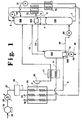
- FIG. 3 is a schematic representation of another preferred embodiment of a cryogenic rectification system wherein feed air is provided for the higher pressure column at two pressure levels.
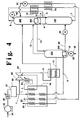
- Figure 4 is a schematic representation of another preferred embodiment of a cryogenic rectification system employing a supercharged turbine.
- the invention enables the higher pressure column of the double column system to operate at lower pressure by uncoupling the dependence of the pressure at the bottom of the higher pressure column to the oxygen product purity.
- the invention achieves energy savings by reducing the feed air compression work required to achieve the requisite head pressure.
- feed air 24 is compressed by passage through base load feed air compressor 25 to a pressure generally within the range of from 262 kPa to 448 kPa (from 38 to 65 psia) and then cooled by passage through cooler 26 to remove heat of compression. Thereafter the pressurized feed air 27 is cleaned of high boiling impurities, such as water vapor and carbon dioxide, by passage through purifier 28 and resulting feed air stream 1 is cooled by indirect heat exchange with return streams in main heat exchanger 70.
- a minor portion 2 generally comprising from 10 to 25 percent of total feed air, is turboexpanded through turboexpander 80 to generate refrigeration, further cooled by passage through heat exchanger 71 and passed into lower pressure column 200.
- Portion 3 generally comprising from 75 to 90 percent of the feed air, is passed through bottom reboiler 350 which is usually located within side column 300 in the lower portion of this column. Within bottom reboiler 350 the compressed feed air is at least partially condensed and thereafter the resulting feed air stream 29 is passed through valve 50 and into higher pressure column 100.
- Higher pressure column 100 is the first or higher pressure column of the double column which also comprises second or lower pressure column 200.
- Higher pressure column 100 operates at a pressure generally within the range of from 207 kPa to 414 kPa (from 30 to 60 psia).
- the feed air is separated by cryogenic rectification into nitrogen-enriched vapor and oxygen-enriched liquid.
- Nitrogen-enriched vapor is passed in stream 4 to main condenser 250 wherein it is condensed by indirect heat exchange with lower pressure column 200 bottom liquid.
- Resulting nitrogen-enriched liquid 31 is divided into streams 6 and 5.
- Stream 6 is passed into column 100 as reflux and stream 5 is cooled by passage through heat exchanger 72 and passed through valve 52 and into column 200 as reflux.
- Oxygen-enriched liquid is withdrawn from the lower portion of column 100 as stream 7, cooled by passage through heat exchanger 73 and then passed through valve 51 and into column 200.
- Column 200 operates at a pressure less than that of column 100 and generally within the range of from 110 kPa to 172 kPa (from 16 to 25 psia).
- Main condenser 250 can be the usual thermosyphon unit, or can be a once through liquid flow unit, or can be a downflow liquid flow arrangement.
- Nitrogen-rich vapor is withdrawn from the upper portion of column 200 as stream 8, warmed by passage through heat exchangers 72, 73 and 70, and removed from the system as stream 33 which may be released to the atmosphere as waste or may be recovered in whole or in part.
- Stream 33 will generally have an oxygen concentration within the range of from 0.1 to 2.5 mole percent with the remainder essentially all nitrogen.
- Crude oxygen liquid having an oxygen concentraticn within the range from 50 to 88 mole percent, is withdrawn from the lower portion of second or lower pressure column 200 and passed as stream 10 into the upper portion of side column 300.
- Side column 300 operates at a pressure which is similar to that of lower pressure column 200 and generally within the range of from 110 kPa to 172 kPa (from 16 to 25 psia).
- the descending crude liquid oxygen is upgraded by cryogenic rectification against upflowing vapor into oxygen product fluid and remaining vapor.
- the remaining vapor generally having an oxygen concentration within the range of from 25 to 65 mole percent and a nitrogen concentration within the range of from 30 to 79 mole percent, is passed in stream 13 from the upper portion of side column 300 into lower pressure column 200.
- the oxygen product fluid having an oxygen concentraticn which exceeds that of the crude oxygen liquid and within the range of from 70 to 99 mole percent, collects as liquid in the lower portion of side column 300 and at least a portion thereof is vaporized by indirect heat exchange against the condensing compressed feed air in bottom reboiler 350 which may be of the conventional thermosyphon type or may be a once through or downflow type unit. This vaporization serves to generate the upflowing vapor for the separation of the crude liquid oxygen within side column 300.
- the oxygen product fluid may be recovered as gas and/or liquid.
- Oxygen product gas may be withdrawn from side column 300 as stream 11, warmed by passage through heat exchangers 71 and 70 and recovered as oxygen product gas 34.
- Oxygen product liquid may be withdrawn from side column 300 as stream 12 passed through valve 53 and recovered as oxygen product liquid 35.
- the oxygen product fluid will have an oxygen concentration within the range of from 70 to 99 mole percent.
- Table 1 lists the results obtained from a computer simulation of the invention carried out using the embodiment illustrated in Figure 1.
- the stream numbers in Table 1 correspond to those of Figure 1.
- This example of the invention is provided for illustrative purposes and is not intended to be limiting.
- the higher pressure column comprises 20 theoretical trays
- the lower pressure column comprises 22 theoretical trays
- the side column comprises 8 theoretical trays.
- the oxygen recovery is 97 percent of the oxygen contained in the feed air.
- the head pressure required to carry out the cryogenic rectification in this example is only about 441 kPa (about 64 psia). This is about 18 percent less than the 538 kPa (78 psia) which would be required to drive a comparable conventional double column separation, thus demonstrating the advantageous results attainable with the practice of this invention.
- FIGs 2, 3 and 4 illustrate other preferred embodiments of the cryogenic rectification system.
- the numerals in Figures 2, 3 and 4 correspond to those of Figure 1 for the common elements and these common elements will not be described again in detail.
- a portion 36 of feed air stream 1 is further compressed through compressor 37, cooled of heat of compression through cooler 38 and passed as stream 30 through main heat exchanger 70 and valve 56 into higher pressure column 100 at a point above the point where feed air stream 29 is passed into column 100.
- Oxygen product liquid stream 12 is increased in pressure by means of liquid pump 60 and pressurized liquid stream 14 is vaporized by passage through main heat exchanger 70 to produce elevated pressure lower purity oxygen product gas stream 15.
- the elevated pressure oxygen product gas will have a pressure within the range of from 207 kPa to 2068 kPa (from 30 to 300 psia).
- a portion 20 of feed air stream 1 is further compressed through compressor 39 prior to passage through main heat exchanger 70 and bottom reboiler 350, while the remaining portion 32 of the feed air stream passes through main heat exchanger 70 but bypasses bottom reboiler 350 and is passed directly into column 100.
- This embodiment enables one to more easily totally condense the feed air passing through bottom reboiler 350 and is advantageous when producing oxygen product having an oxygen purity within the range of from 90 to 99 mole percent.
- feed air portion 2 is taken from stream 1 upstream of main heat exchanger 70 and compressed through compressor 90.
- the resulting stream is cooled through cooler 91 to remove heat of compression and passed partially through main heat exchanger 70.
- turboexpander 80 is directly coupled to compressor 90 serving to drive compressor 90 with energy released by the expansion of pressurized gas stream 2 through turboexpander 80.
- This embodiment is advantageous from an equipment standpoint and can also be useful for producing oxygen product having an oxygen purity within the range of from 90 to 99 mole percent.
Description
- This invention relates generally to cryogenic rectification and more particularly to the production of lower purity oxygen.
- The cryogenic separation of air is a well established industrial process. Cryogenic air separation involves the filtering of the feed air to remove particulate matter and compression of that feed air to supply the energy required for separation. Following the compression the feed air is cleaned of high boiling impurities such as carbon dioxide and water vapor, cooled, and then separated into products by cryogenic rectification. The separation columns are operated at cryogenic temperatures to allow the gas and liquid contacting necessary for separation by distillation, and the separated products are then returned to ambient temperature conditions against the cooling feed air stream.
- The most common cryogenic air separation system for the production of oxygen is the double column system which employs a higher pressure column and a lower pressure column in heat exchange relation at a main condenser. In this system the head pressure is the pressure discharge at the base load air compressor which is set by the pressure at the bottom of the higher pressure column plus the pressure drop in piping and apparatus between the base load air compressor and the higher pressure column. In turn, the pressure at the bottom of the higher pressure column is set by the pressure drop of the stream from the top of the lower pressure column to the atmosphere, by the added pressure difference to the bottom of the lower pressure column, by the temperature difference across the main condenser which sets the high pressure nitrogen condensing pressure at the top of the higher pressure column, and by the added pressure drop to the bottom of the higher pressure column. In conventional systems the pressure at the bottom of the higher pressure column is generally within the range of from 483 kPa to 552 kPa (from 70 to 80 pounds per square inch absolute (psia)) resulting in a head pressure generally within the range of from 531 kPa to 600 kPa (from 77 to 87 psia).
- The conventional double column system enables the separation of air with good energy efficiency and excellent product purity. However, when lower purity oxygen, i.e. oxygen having a purity of 99 mole percent or less, is desired, the conventional system is less efficient because it has more air separation capability than is being utilized. Since the demand for lower purity oxygen is increasing in applications such as glassmaking, steelmaking and energy production, it is desirable to have a double column system which can produce lower purity oxygen at lower operating costs.
- EP-A-0 633 438, the content of which constitutes prior art in conformity with Article 54.3 EPC as to the designated states DE, ES, FR, GB, IT, and NL, discloses a method for separating air, whereby a stream of cooled and purified air is partially condensed by passage through a condenser-reboiler of a side column prior to introduction into a higher pressure column of a double column which also includes a lower pressure column in communication with the side column. Liquid from the bottom of the lower pressure column is passed into the top of the side column, and vapor from the top of the side column is returned to the bottom of the lower pressure column. In the higher pressure column, the air is separated into oxygen-enriched liquid and nitrogen vapor, whereby the oxygen-enriched liquid after withdrawal from a lower portion of the higher pressure column is separated by means of a separator into a vapor portion and a liquid portion. The vapor portion withdrawn from the separator is divided into a first portion being passed into the lower pressure column, and a second portion being urged by a pump into the higher pressure column, whereas the liquid portion from the separator is completely passed into the lower pressure column.
- From US-A-2 664 719 a rectification system for producing high-purity oxygen in a side column as well as lower-purity oxygen in a main column is known, the main column of the rectification system comprising a higher pressure column and a lower pressure column. In this prior rectification system, feed air is compressed, cooled and passed into a scrubber chamber. From the top of the scrubber chamber, air is withdrawn and divided into a first portion which is introduced as gaseous feed into the higher pressure column, and a second portion which is condensed in a heating coil within the side column and thereafter passed into the lower pressure column. Crude oxygen from the bottom of the higher pressure column is conducted to an intermediate part of the lower pressure column, and a gravity flow of lower-purity oxygen from the bottom of the lower pressure column is passed to the side column the upper end of which is connected to the lower pressure column to conduct effluent vapor from the side column to the lower pressure column. The high-purity oxygen product withdrawn from the side column is a fluid with an oxygen concentration of over 99%.
- In DE-C-921 809 a method for producing pure oxygen and oxygen of lower purity is disclosed, whereby compressed air is cooled in switchable heat exchangers or cold accumulators, freed from water vapor and carbon dioxide and thereafter passed into a higher pressure column of a double column system also including a lower pressure column. Liquid oxygen is withdrawn at the bottom of the lower pressure column, and a first portion of the liquid oxygen is heated to ambient temperature and recovered as lower purity oxygen product after being vaporized in a heat exchanger. A second portion of the liquid oxygen withdrawn from the lower pressure column undergoes a secondary distillation in a side column heated by nitrogen or air passed to a bottom reboiler of the side column, whereby pure oxygen is recovered as bottom product. A lower purity oxygen withdrawn from the top of the side column is re-introduced into the lower pressure column.
- It is an object of this invention to provide an improved double column cryogenic rectification method for producing lower purity oxygen.
- The above and other objects which will become apparent to the one skilled in the art upon a reading of this disclosure are attained by the present invention, which is:
- A cryogenic rectification method for producing lower purity oxygen comprising;
- (A) compressing feed air;
- (B) at least partially condensing the compressed feed air and passing the resulting feed air into the higher pressure column of a double column which also includes a lower pressure column;
- (C) passing crude liquid oxygen comprising from 50 to 88 mole percent oxygen from the lower pressure column into a side column;
- (D) separating the crude liquid oxygen by cryogenic rectification within the side column into oxygen product fluid and remaining vapor;
- (E) passing remaining vapor from the side column into the lower pressure column;
- (F) at least partially vaporizing the oxygen product fluid by indirect heat exchange with the compressed feed air to carry out the said at least partial condensation of the compressed feed air; and
- (G) recovering oxygen product fluid as product lower purity oxygen having an oxygen concentration which exceeds that of the crude liquid oxygen and which oxygen concentration is 99 mole percent or less.
-
- As used herein, the term "column" means a distillation or fractionation column or zone, i.e., a contacting column or zone wherein liquid and vapor phases are countercurrently contacted to effect separation of a fluid mixture, as for example, by contacting of the vapor and liquid phases on a series of vertically spaced trays or plates mounted within the column and/or on packing elements such as structured or random packing. For a further discussion of distillation columns, see the Chemical Engineer's Handbook fifth edition, edited by R. H. Perry and C. H. Chilton, McGraw-Hill Book Company, New York,
Section 13, The Continuous Distillation Process. The term, double column is used to mean a higher pressure column having its upper end in heat exchange relation with the lower end of a lower pressure column. A further discussion of double columns appears in Ruheman "The Separation of Gases", Oxford University Press, 1949, Chapter VII, Commercial Air Separation. - Vapor and liquid contacting separation processes depend on the difference in vapor pressures for the components. The high vapor pressure (or more volatile or low boiling) component will tend to concentrate in the vapor phase whereas the low vapor pressure (or less volatile or high boiling) component will tend to concentrate in the liquid phase. Partial condensation is the separation process whereby cooling of a vapor mixture can be used to concentrate the volatile component(s) in the vapor phase and thereby the less volatile component(s) in the liquid phase. Rectification, or continuous distillation, is the separation process that combines successive partial vaporizations and condensations as obtained by a countercurrent treatment of the vapor and liquid phases. The countercurrent contacting of the vapor and liquid phases is generally adiabatic and can include integral (stagewise) or differential (continuous) contact between the phases. Separation process arrangements that utilize the principles of rectification to separate mixtures are often interchangeably termed rectification columns, distillation columns, or fractionation columns. Cryogenic rectification is a rectification process carried out at least in part at temperatures at or below 150 degrees Kelvin (K).
- As used herein, the term "indirect heat exchange" means the bringing of two fluid streams into heat exchange relation without any physical contact or intermixing of the fluids with each other.
- As used herein the term "bottom reboiler" means a heat exchange device which generates column upflow vapor from column bottom liquid.
- As used herein, the terms "turboexpansion" and "turboexpander" mean respectively method and apparatus for the flow of high pressure gas through a turbine to reduce the pressure and the temperature of the gas thereby generating refrigeration.
- As used herein, the terms "upper portion" and "lower portion" mean those sections of a column respectively above and below the mid point of the column.
- As used herein, the term "feed air" means a mixture comprising primarily nitrogen and oxygen, such as ambient air.
- As used herein the term "lower purity oxygen" means a fluid having an oxygen concentration of 99 mole percent or less.
- Figure 1 is a schematic representation of one preferred embodiment of a cryogenic rectification system suitable for carrying out the cryogenic rectification method of this invention.
- Figure 2 is a schematic representation of another preferred embodiment of a cryogenic rectification system wherein elevated pressure oxygen product may be produced.
- Figure 3 is a schematic representation of another preferred embodiment of a cryogenic rectification system wherein feed air is provided for the higher pressure column at two pressure levels.
- Figure 4 is a schematic representation of another preferred embodiment of a cryogenic rectification system employing a supercharged turbine.
- In general, the invention enables the higher pressure column of the double column system to operate at lower pressure by uncoupling the dependence of the pressure at the bottom of the higher pressure column to the oxygen product purity. Thus the invention achieves energy savings by reducing the feed air compression work required to achieve the requisite head pressure.
- The invention will be described in detail with reference to the Drawings.
- Referring now to Figure 1, feed
air 24 is compressed by passage through base loadfeed air compressor 25 to a pressure generally within the range of from 262 kPa to 448 kPa (from 38 to 65 psia) and then cooled by passage through cooler 26 to remove heat of compression. Thereafter thepressurized feed air 27 is cleaned of high boiling impurities, such as water vapor and carbon dioxide, by passage throughpurifier 28 and resultingfeed air stream 1 is cooled by indirect heat exchange with return streams inmain heat exchanger 70. Aminor portion 2, generally comprising from 10 to 25 percent of total feed air, is turboexpanded throughturboexpander 80 to generate refrigeration, further cooled by passage throughheat exchanger 71 and passed intolower pressure column 200. -
Portion 3, generally comprising from 75 to 90 percent of the feed air, is passed throughbottom reboiler 350 which is usually located withinside column 300 in the lower portion of this column. Withinbottom reboiler 350 the compressed feed air is at least partially condensed and thereafter the resultingfeed air stream 29 is passed throughvalve 50 and intohigher pressure column 100. -
Higher pressure column 100 is the first or higher pressure column of the double column which also comprises second orlower pressure column 200.Higher pressure column 100 operates at a pressure generally within the range of from 207 kPa to 414 kPa (from 30 to 60 psia). Withinhigher pressure column 100 the feed air is separated by cryogenic rectification into nitrogen-enriched vapor and oxygen-enriched liquid. Nitrogen-enriched vapor is passed in stream 4 tomain condenser 250 wherein it is condensed by indirect heat exchange withlower pressure column 200 bottom liquid. Resulting nitrogen-enrichedliquid 31 is divided intostreams Stream 6 is passed intocolumn 100 as reflux andstream 5 is cooled by passage throughheat exchanger 72 and passed throughvalve 52 and intocolumn 200 as reflux. Oxygen-enriched liquid is withdrawn from the lower portion ofcolumn 100 asstream 7, cooled by passage throughheat exchanger 73 and then passed throughvalve 51 and intocolumn 200.Column 200 operates at a pressure less than that ofcolumn 100 and generally within the range of from 110 kPa to 172 kPa (from 16 to 25 psia).Main condenser 250 can be the usual thermosyphon unit, or can be a once through liquid flow unit, or can be a downflow liquid flow arrangement. - Within
lower pressure column 200 the various feeds into this column are separated by cryogenic rectification into nitrogen-rich vapor and crude liquid oxygen. Nitrogen-rich vapor is withdrawn from the upper portion ofcolumn 200 asstream 8, warmed by passage throughheat exchangers stream 33 which may be released to the atmosphere as waste or may be recovered in whole or in part.Stream 33 will generally have an oxygen concentration within the range of from 0.1 to 2.5 mole percent with the remainder essentially all nitrogen. Crude oxygen liquid, having an oxygen concentraticn within the range from 50 to 88 mole percent, is withdrawn from the lower portion of second orlower pressure column 200 and passed asstream 10 into the upper portion ofside column 300. -
Side column 300 operates at a pressure which is similar to that oflower pressure column 200 and generally within the range of from 110 kPa to 172 kPa (from 16 to 25 psia). Withinside column 300 the descending crude liquid oxygen is upgraded by cryogenic rectification against upflowing vapor into oxygen product fluid and remaining vapor. The remaining vapor, generally having an oxygen concentration within the range of from 25 to 65 mole percent and a nitrogen concentration within the range of from 30 to 79 mole percent, is passed instream 13 from the upper portion ofside column 300 intolower pressure column 200. - The oxygen product fluid, having an oxygen concentraticn which exceeds that of the crude oxygen liquid and within the range of from 70 to 99 mole percent, collects as liquid in the lower portion of
side column 300 and at least a portion thereof is vaporized by indirect heat exchange against the condensing compressed feed air inbottom reboiler 350 which may be of the conventional thermosyphon type or may be a once through or downflow type unit. This vaporization serves to generate the upflowing vapor for the separation of the crude liquid oxygen withinside column 300. The oxygen product fluid may be recovered as gas and/or liquid. Oxygen product gas may be withdrawn fromside column 300 asstream 11, warmed by passage throughheat exchangers oxygen product gas 34. Oxygen product liquid may be withdrawn fromside column 300 asstream 12 passed throughvalve 53 and recovered asoxygen product liquid 35. The oxygen product fluid will have an oxygen concentration within the range of from 70 to 99 mole percent. - Table 1 lists the results obtained from a computer simulation of the invention carried out using the embodiment illustrated in Figure 1. The stream numbers in Table 1 correspond to those of Figure 1. This example of the invention is provided for illustrative purposes and is not intended to be limiting. In this example the higher pressure column comprises 20 theoretical trays, the lower pressure column comprises 22 theoretical trays, and the side column comprises 8 theoretical trays.
STREAM NO. FLOW PRESSURE TEMP (°K) COMPOSITION (Mole Percent) (kg mole/hr.) (lb. mole/hr.) (kPa) (psia) N2 Ar O2 1 45.36 100 413.7 60 289 78 0.9 20.9 2 4.45 9.8 409.5 59.4 139 78 0.9 20.9 3 40.91 90.2 395.8 57.4 95 78 0.9 20.9 7 28.21 62.2 385.4 55.9 94 68.5 1.2 30.3 10 14.97 33 126.2 18.3 89 13.6 3.4 83 11 9.66 21.3 126.9 18.4 92 1.9 3.1 95 12 0.05 0.1 126.9 18.4 92 0.5 2.1 97.4 13 5.26 11.6 126.2 18.3 89 35.2 3.8 61 - In this example the oxygen recovery is 97 percent of the oxygen contained in the feed air. The head pressure required to carry out the cryogenic rectification in this example is only about 441 kPa (about 64 psia). This is about 18 percent less than the 538 kPa (78 psia) which would be required to drive a comparable conventional double column separation, thus demonstrating the advantageous results attainable with the practice of this invention.
- Figures 2, 3 and 4 illustrate other preferred embodiments of the cryogenic rectification system. The numerals in Figures 2, 3 and 4 correspond to those of Figure 1 for the common elements and these common elements will not be described again in detail.
- Referring now to Figure 2, a
portion 36 offeed air stream 1 is further compressed throughcompressor 37, cooled of heat of compression through cooler 38 and passed asstream 30 throughmain heat exchanger 70 andvalve 56 intohigher pressure column 100 at a point above the point wherefeed air stream 29 is passed intocolumn 100. Oxygenproduct liquid stream 12 is increased in pressure by means ofliquid pump 60 and pressurizedliquid stream 14 is vaporized by passage throughmain heat exchanger 70 to produce elevated pressure lower purity oxygenproduct gas stream 15. Generally the elevated pressure oxygen product gas will have a pressure within the range of from 207 kPa to 2068 kPa (from 30 to 300 psia). Depending upon the heat exchanger design requirements, it may be preferred that the boiling ofstream 14 against condensingstream 30 be carried out in a separate heat exchanger (not shown) located betweenliquid pump 60 andmain heat exchanger 70. - In the embodiment illustrated in Figure 3, a
portion 20 offeed air stream 1 is further compressed throughcompressor 39 prior to passage throughmain heat exchanger 70 andbottom reboiler 350, while the remainingportion 32 of the feed air stream passes throughmain heat exchanger 70 but bypassesbottom reboiler 350 and is passed directly intocolumn 100. This embodiment enables one to more easily totally condense the feed air passing throughbottom reboiler 350 and is advantageous when producing oxygen product having an oxygen purity within the range of from 90 to 99 mole percent. - In the embodiment illustrated in Figure 4, feed
air portion 2 is taken fromstream 1 upstream ofmain heat exchanger 70 and compressed throughcompressor 90. The resulting stream is cooled through cooler 91 to remove heat of compression and passed partially throughmain heat exchanger 70. Thereafter the stream is turboexpanded throughturboexpander 80 to generate refrigeration and from there is passed throughheat exchanger 71 and intolower pressure column 200.Turboexpander 80 is directly coupled tocompressor 90 serving to drivecompressor 90 with energy released by the expansion ofpressurized gas stream 2 throughturboexpander 80. This embodiment is advantageous from an equipment standpoint and can also be useful for producing oxygen product having an oxygen purity within the range of from 90 to 99 mole percent. - Now by the use of this invention one may employ a double column to effectively produce lower purity oxygen while operating at lower pressures and thus with reduced costs that would be necessary with a conventional double column system.
Claims (5)
- A cryogenic rectification method for producing lower purity oxygen comprising:(A) compressing (25) feed air (24);(B) at least partially condensing (350) the compressed feed air (1, 3) and passing the resulting feed air (29) into the higher pressure column (100) of a double column which also includes a lower pressure column (200);(C) passing crude liquid oxygen (10) comprising from 50 to 88 mole percent oxygen from the lower pressure column (200) into a side column (300);(D) separating the crude liquid oxygen (10) by cryogenic rectification within the side column (300) into oxygen product fluid and remaining vapor (13);(E) passing remaining vapor (13) from the side column (300) into the lower pressure column (200);(F) at least partially vaporizing the oxygen product fluid by indirect heat exchange with the compressed feed air (1, 3) to carry out the said at least partial condensation of the compressed feed air (1,3); and(G) recovering oxygen product fluid as product lower purity oxygen (34, 35) having an oxygen concentration which exceeds that of the crude liquid oxygen (10) and which oxygen concentration is 99 mole percent or less.
- The method of claim 1 wherein the oxygen product fluid is recovered as gas (34).
- The method of claim 1 wherein the oxygen product fluid is recovered as liquid (35).
- The method of claim 1 wherein oxygen product fluid is withdraw from the side column (300) as liquid (12), increased in pressure (60), and vaporized (70) prior to recovery.
- The method of claim 1 further comprising turboexpanding (80) a portion (2) of the compressed feed air (1) and passing the turboexpanded feed air into the lower pressure column (200).
Applications Claiming Priority (2)
| Application Number | Priority Date | Filing Date | Title |
|---|---|---|---|
| US08/317,973 US5463871A (en) | 1994-10-04 | 1994-10-04 | Side column cryogenic rectification system for producing lower purity oxygen |
| US317973 | 1994-10-04 |
Publications (3)
| Publication Number | Publication Date |
|---|---|
| EP0706020A2 EP0706020A2 (en) | 1996-04-10 |
| EP0706020A3 EP0706020A3 (en) | 1996-07-03 |
| EP0706020B1 true EP0706020B1 (en) | 1999-07-28 |
Family
ID=23236076
Family Applications (1)
| Application Number | Title | Priority Date | Filing Date |
|---|---|---|---|
| EP95115584A Revoked EP0706020B1 (en) | 1994-10-04 | 1995-10-03 | Side column cryogenic rectification system for producing lower purity oxygen |
Country Status (9)
| Country | Link |
|---|---|
| US (1) | US5463871A (en) |
| EP (1) | EP0706020B1 (en) |
| JP (1) | JP3182326B2 (en) |
| KR (1) | KR100261915B1 (en) |
| CN (1) | CN1103041C (en) |
| BR (1) | BR9504263A (en) |
| CA (1) | CA2159751C (en) |
| DE (1) | DE69511028T2 (en) |
| ES (1) | ES2134391T3 (en) |
Families Citing this family (38)
| Publication number | Priority date | Publication date | Assignee | Title |
|---|---|---|---|---|
| US5596886A (en) * | 1996-04-05 | 1997-01-28 | Praxair Technology, Inc. | Cryogenic rectification system for producing gaseous oxygen and high purity nitrogen |
| US5628207A (en) * | 1996-04-05 | 1997-05-13 | Praxair Technology, Inc. | Cryogenic Rectification system for producing lower purity gaseous oxygen and high purity oxygen |
| US5669236A (en) * | 1996-08-05 | 1997-09-23 | Praxair Technology, Inc. | Cryogenic rectification system for producing low purity oxygen and high purity oxygen |
| US5697229A (en) * | 1996-08-07 | 1997-12-16 | Air Products And Chemicals, Inc. | Process to produce nitrogen using a double column plus an auxiliary low pressure separation zone |
| US5675977A (en) * | 1996-11-07 | 1997-10-14 | Praxair Technology, Inc. | Cryogenic rectification system with kettle liquid column |
| US5682766A (en) * | 1996-12-12 | 1997-11-04 | Praxair Technology, Inc. | Cryogenic rectification system for producing lower purity oxygen and higher purity oxygen |
| US5836174A (en) * | 1997-05-30 | 1998-11-17 | Praxair Technology, Inc. | Cryogenic rectification system for producing multi-purity oxygen |
| US5873264A (en) * | 1997-09-18 | 1999-02-23 | Praxair Technology, Inc. | Cryogenic rectification system with intermediate third column reboil |
| US5881570A (en) * | 1998-04-06 | 1999-03-16 | Praxair Technology, Inc. | Cryogenic rectification apparatus for producing high purity oxygen or low purity oxygen |
| US5934104A (en) * | 1998-06-02 | 1999-08-10 | Air Products And Chemicals, Inc. | Multiple column nitrogen generators with oxygen coproduction |
| US5916262A (en) * | 1998-09-08 | 1999-06-29 | Praxair Technology, Inc. | Cryogenic rectification system for producing low purity oxygen and high purity oxygen |
| FR2787561A1 (en) * | 1998-12-22 | 2000-06-23 | Air Liquide | Cryogenic distillation of air uses double column with air supply to medium pressure column and oxygen rich fluid from bottom of both low pressure and auxiliary columns |
| FR2787559A1 (en) * | 1998-12-22 | 2000-06-23 | Air Liquide | Air separation using cryogenic distillation has double column receiving compressed, cooled, and expanded air to produce oxygen rich and nitrogen rich fractions |
| US6134915A (en) * | 1999-03-30 | 2000-10-24 | The Boc Group, Inc. | Distillation column arrangement for air separation plant |
| US6237366B1 (en) | 2000-04-14 | 2001-05-29 | Praxair Technology, Inc. | Cryogenic air separation system using an integrated core |
| US6295836B1 (en) | 2000-04-14 | 2001-10-02 | Praxair Technology, Inc. | Cryogenic air separation system with integrated mass and heat transfer |
| US6279344B1 (en) | 2000-06-01 | 2001-08-28 | Praxair Technology, Inc. | Cryogenic air separation system for producing oxygen |
| US6536234B1 (en) | 2002-02-05 | 2003-03-25 | Praxair Technology, Inc. | Three column cryogenic air separation system with dual pressure air feeds |
| US20040020239A1 (en) * | 2002-03-08 | 2004-02-05 | Laforce Craig Steven | Method of producing an oxygen-enriched air stream |
| CA2482454C (en) * | 2002-04-11 | 2011-12-20 | Richard A. Haase | Water combustion technology-methods, processes, systems and apparatus for the combustion of hydrogen and oxygen |
| US6626008B1 (en) | 2002-12-11 | 2003-09-30 | Praxair Technology, Inc. | Cold compression cryogenic rectification system for producing low purity oxygen |
| US6622520B1 (en) | 2002-12-11 | 2003-09-23 | Praxair Technology, Inc. | Cryogenic rectification system for producing low purity oxygen using shelf vapor turboexpansion |
| US8268269B2 (en) | 2006-01-24 | 2012-09-18 | Clearvalue Technologies, Inc. | Manufacture of water chemistries |
| US8429933B2 (en) | 2007-11-14 | 2013-04-30 | Praxair Technology, Inc. | Method for varying liquid production in an air separation plant with use of a variable speed turboexpander |
| US20090139263A1 (en) * | 2007-12-04 | 2009-06-04 | Air Products And Chemicals, Inc. | Thermosyphon reboiler for the denitrogenation of liquid natural gas |
| FR2930331B1 (en) * | 2008-04-22 | 2013-09-13 | Air Liquide | METHOD AND APPARATUS FOR AIR SEPARATION BY CRYOGENIC DISTILLATION |
| JP5032407B2 (en) * | 2008-07-24 | 2012-09-26 | 大陽日酸株式会社 | Nitrogen production method and apparatus |
| FR2946735B1 (en) * | 2009-06-12 | 2012-07-13 | Air Liquide | APPARATUS AND METHOD FOR AIR SEPARATION BY CRYOGENIC DISTILLATION. |
| CN102003867A (en) * | 2010-11-09 | 2011-04-06 | 上海启元科技发展有限公司 | Method for producing high-purity nitrogen and low-purity oxygen |
| US8899075B2 (en) * | 2010-11-18 | 2014-12-02 | Praxair Technology, Inc. | Air separation method and apparatus |
| US20120125044A1 (en) * | 2010-11-19 | 2012-05-24 | Neil Mark Prosser | Feed compression method and apparatus for air separation process |
| CN102080921B (en) * | 2010-12-23 | 2013-09-04 | 上海启元科技发展有限公司 | Method and device for producing high-pressure nitrogen and low-pressure oxygen |
| CN102052821A (en) * | 2011-01-07 | 2011-05-11 | 苏州市兴鲁空分设备科技发展有限公司 | Air separation method |
| CN102538397A (en) * | 2012-01-18 | 2012-07-04 | 开封黄河空分集团有限公司 | Process for making nitrogen by air separation or making nitrogen and simultaneously producing oxygen in attached manner |
| CN102721263A (en) * | 2012-07-12 | 2012-10-10 | 杭州杭氧股份有限公司 | System and method for separating air by utilizing cryogenic cooling technology |
| CN103438663A (en) * | 2013-07-11 | 2013-12-11 | 开封黄河空分集团有限公司 | Device and process for preparing high-purity oxygen and nitrogen under ultra-low pressure |
| CN103453314A (en) * | 2013-08-15 | 2013-12-18 | 湖北和远气体股份有限公司 | Method for adding rich oxygen in liquid waste treatment process |
| CN109737691B (en) * | 2019-01-31 | 2020-05-19 | 东北大学 | Air separation system of iron and steel enterprise |
Family Cites Families (23)
| Publication number | Priority date | Publication date | Assignee | Title |
|---|---|---|---|---|
| US2664719A (en) * | 1950-07-05 | 1954-01-05 | Union Carbide & Carbon Corp | Process and apparatus for separating gas mixtures |
| DE921809C (en) * | 1952-07-04 | 1954-12-30 | Adolf Messer G M B H | Process for the production of pure oxygen in addition to the production of oxygen of lower purity |
| US2873583A (en) * | 1954-05-04 | 1959-02-17 | Union Carbide Corp | Dual pressure cycle for air separation |
| US3113854A (en) * | 1960-08-25 | 1963-12-10 | Air Prod & Chem | Method and apparatus for separating gaseous mixtures |
| US4224045A (en) * | 1978-08-23 | 1980-09-23 | Union Carbide Corporation | Cryogenic system for producing low-purity oxygen |
| US4410343A (en) * | 1981-12-24 | 1983-10-18 | Union Carbide Corporation | Air boiling process to produce low purity oxygen |
| US4560398A (en) * | 1984-07-06 | 1985-12-24 | Union Carbide Corporation | Air separation process to produce elevated pressure oxygen |
| US4617036A (en) * | 1985-10-29 | 1986-10-14 | Air Products And Chemicals, Inc. | Tonnage nitrogen air separation with side reboiler condenser |
| US4702757A (en) * | 1986-08-20 | 1987-10-27 | Air Products And Chemicals, Inc. | Dual air pressure cycle to produce low purity oxygen |
| US4769055A (en) * | 1987-02-03 | 1988-09-06 | Erickson Donald C | Companded total condensation reboil cryogenic air separation |
| US4895583A (en) * | 1989-01-12 | 1990-01-23 | The Boc Group, Inc. | Apparatus and method for separating air |
| EP0383994A3 (en) * | 1989-02-23 | 1990-11-07 | Linde Aktiengesellschaft | Air rectification process and apparatus |
| US4936099A (en) * | 1989-05-19 | 1990-06-26 | Air Products And Chemicals, Inc. | Air separation process for the production of oxygen-rich and nitrogen-rich products |
| US5006139A (en) * | 1990-03-09 | 1991-04-09 | Air Products And Chemicals, Inc. | Cryogenic air separation process for the production of nitrogen |
| US5129932A (en) * | 1990-06-12 | 1992-07-14 | Air Products And Chemicals, Inc. | Cryogenic process for the separation of air to produce moderate pressure nitrogen |
| FR2685459B1 (en) * | 1991-12-18 | 1994-02-11 | Air Liquide | PROCESS AND PLANT FOR PRODUCING IMPURATED OXYGEN. |
| CN1071444C (en) * | 1992-02-21 | 2001-09-19 | 普拉塞尔技术有限公司 | Cryogenic air separation system for producing gaseous oxygen |
| US5245832A (en) * | 1992-04-20 | 1993-09-21 | Praxair Technology, Inc. | Triple column cryogenic rectification system |
| US5233838A (en) * | 1992-06-01 | 1993-08-10 | Praxair Technology, Inc. | Auxiliary column cryogenic rectification system |
| GB9405071D0 (en) * | 1993-07-05 | 1994-04-27 | Boc Group Plc | Air separation |
| US5341646A (en) * | 1993-07-15 | 1994-08-30 | Air Products And Chemicals, Inc. | Triple column distillation system for oxygen and pressurized nitrogen production |
| US5337570A (en) * | 1993-07-22 | 1994-08-16 | Praxair Technology, Inc. | Cryogenic rectification system for producing lower purity oxygen |
| US5386691A (en) * | 1994-01-12 | 1995-02-07 | Praxair Technology, Inc. | Cryogenic air separation system with kettle vapor bypass |
-
1994
- 1994-10-04 US US08/317,973 patent/US5463871A/en not_active Expired - Lifetime
-
1995
- 1995-10-02 KR KR1019950033653A patent/KR100261915B1/en not_active IP Right Cessation
- 1995-10-03 DE DE69511028T patent/DE69511028T2/en not_active Revoked
- 1995-10-03 JP JP27822995A patent/JP3182326B2/en not_active Expired - Lifetime
- 1995-10-03 CA CA002159751A patent/CA2159751C/en not_active Expired - Fee Related
- 1995-10-03 CN CN95102554A patent/CN1103041C/en not_active Expired - Fee Related
- 1995-10-03 ES ES95115584T patent/ES2134391T3/en not_active Expired - Lifetime
- 1995-10-03 BR BR9504263A patent/BR9504263A/en not_active IP Right Cessation
- 1995-10-03 EP EP95115584A patent/EP0706020B1/en not_active Revoked
Also Published As
| Publication number | Publication date |
|---|---|
| DE69511028T2 (en) | 2000-01-27 |
| US5463871A (en) | 1995-11-07 |
| CN1126305A (en) | 1996-07-10 |
| EP0706020A2 (en) | 1996-04-10 |
| CA2159751C (en) | 1997-11-25 |
| CA2159751A1 (en) | 1996-04-05 |
| ES2134391T3 (en) | 1999-10-01 |
| EP0706020A3 (en) | 1996-07-03 |
| CN1103041C (en) | 2003-03-12 |
| DE69511028D1 (en) | 1999-09-02 |
| BR9504263A (en) | 1998-10-27 |
| JPH08210769A (en) | 1996-08-20 |
| JP3182326B2 (en) | 2001-07-03 |
| KR960013411A (en) | 1996-05-22 |
| KR100261915B1 (en) | 2000-07-15 |
Similar Documents
| Publication | Publication Date | Title |
|---|---|---|
| EP0706020B1 (en) | Side column cryogenic rectification system for producing lower purity oxygen | |
| EP0674144B1 (en) | Cryogenic rectification system for producing elevated pressure nitrogen | |
| EP0762065B1 (en) | Cryogenic air separation blast furnace system | |
| EP0635690B1 (en) | Cryogenic rectification system for producing lower purity oxygen | |
| EP0464630A1 (en) | Cryogenic air separation with dual product boiler | |
| US5469710A (en) | Cryogenic rectification system with enhanced argon recovery | |
| EP0666459A1 (en) | Cryogenic rectification system with hybrid product boiler | |
| EP0766053B1 (en) | Cryogenic rectification system for producing dual purity oxygen | |
| US5233838A (en) | Auxiliary column cryogenic rectification system | |
| EP0594214B1 (en) | Cryogenic rectification system with thermally integrated argon column | |
| CA2092454C (en) | High recovery cryogenic rectification system | |
| CA2196354C (en) | Air boiling cryogenic rectification system with staged feed air condensation | |
| US5682766A (en) | Cryogenic rectification system for producing lower purity oxygen and higher purity oxygen | |
| US5916262A (en) | Cryogenic rectification system for producing low purity oxygen and high purity oxygen | |
| EP0567098B1 (en) | Cryogenic rectification system with dual heat pump | |
| US5596886A (en) | Cryogenic rectification system for producing gaseous oxygen and high purity nitrogen | |
| EP0959313B1 (en) | Cryogenic rectification system with integral phase separator with product boiler | |
| CA2196353C (en) | Single column cryogenic rectification system for lower purity oxygen production | |
| CA2200249C (en) | Cryogenic rectification system with staged feed air condensation | |
| US5682765A (en) | Cryogenic rectification system for producing argon and lower purity oxygen | |
| US6073462A (en) | Cryogenic air separation system for producing elevated pressure oxygen | |
| US5806342A (en) | Cryogenic rectification system for producing low purity oxygen and high purity oxygen | |
| US5836175A (en) | Dual column cryogenic rectification system for producing nitrogen |
Legal Events
| Date | Code | Title | Description |
|---|---|---|---|
| PUAI | Public reference made under article 153(3) epc to a published international application that has entered the european phase |
Free format text: ORIGINAL CODE: 0009012 |
|
| AK | Designated contracting states |
Kind code of ref document: A2 Designated state(s): BE DE ES FR GB IT NL |
|
| PUAL | Search report despatched |
Free format text: ORIGINAL CODE: 0009013 |
|
| AK | Designated contracting states |
Kind code of ref document: A3 Designated state(s): BE DE ES FR GB IT NL |
|
| 17P | Request for examination filed |
Effective date: 19960726 |
|
| 17Q | First examination report despatched |
Effective date: 19980209 |
|
| GRAG | Despatch of communication of intention to grant |
Free format text: ORIGINAL CODE: EPIDOS AGRA |
|
| GRAG | Despatch of communication of intention to grant |
Free format text: ORIGINAL CODE: EPIDOS AGRA |
|
| GRAH | Despatch of communication of intention to grant a patent |
Free format text: ORIGINAL CODE: EPIDOS IGRA |
|
| GRAH | Despatch of communication of intention to grant a patent |
Free format text: ORIGINAL CODE: EPIDOS IGRA |
|
| GRAA | (expected) grant |
Free format text: ORIGINAL CODE: 0009210 |
|
| AK | Designated contracting states |
Kind code of ref document: B1 Designated state(s): BE DE ES FR GB IT NL |
|
| REF | Corresponds to: |
Ref document number: 69511028 Country of ref document: DE Date of ref document: 19990902 |
|
| REG | Reference to a national code |
Ref country code: ES Ref legal event code: FG2A Ref document number: 2134391 Country of ref document: ES Kind code of ref document: T3 |
|
| ET | Fr: translation filed | ||
| PLBQ | Unpublished change to opponent data |
Free format text: ORIGINAL CODE: EPIDOS OPPO |
|
| PLBI | Opposition filed |
Free format text: ORIGINAL CODE: 0009260 |
|
| PLBQ | Unpublished change to opponent data |
Free format text: ORIGINAL CODE: EPIDOS OPPO |
|
| PLBI | Opposition filed |
Free format text: ORIGINAL CODE: 0009260 |
|
| PLBF | Reply of patent proprietor to notice(s) of opposition |
Free format text: ORIGINAL CODE: EPIDOS OBSO |
|
| 26 | Opposition filed |
Opponent name: L'AIR LIQUIDE, SOCIETE ANONYME POUR L'ETUDE ET L'E Effective date: 20000427 |
|
| 26 | Opposition filed |
Opponent name: LINDE AKTIENGESELLSCHAFT Effective date: 20000426 Opponent name: L'AIR LIQUIDE, SOCIETE ANONYME POUR L'ETUDE ET L'E Effective date: 20000427 |
|
| NLR1 | Nl: opposition has been filed with the epo |
Opponent name: L'AIR LIQUIDE, SOCIETE ANONYME POUR L'ETUDE ET L'E |
|
| NLR1 | Nl: opposition has been filed with the epo |
Opponent name: LINDE AKTIENGESELLSCHAFT Opponent name: L'AIR LIQUIDE, SOCIETE ANONYME POUR L'ETUDE ET L'E |
|
| PLBF | Reply of patent proprietor to notice(s) of opposition |
Free format text: ORIGINAL CODE: EPIDOS OBSO |
|
| PLBF | Reply of patent proprietor to notice(s) of opposition |
Free format text: ORIGINAL CODE: EPIDOS OBSO |
|
| PLBF | Reply of patent proprietor to notice(s) of opposition |
Free format text: ORIGINAL CODE: EPIDOS OBSO |
|
| PGFP | Annual fee paid to national office [announced via postgrant information from national office to epo] |
Ref country code: NL Payment date: 20010925 Year of fee payment: 7 |
|
| PGFP | Annual fee paid to national office [announced via postgrant information from national office to epo] |
Ref country code: BE Payment date: 20011010 Year of fee payment: 7 |
|
| REG | Reference to a national code |
Ref country code: GB Ref legal event code: IF02 |
|
| PLAW | Interlocutory decision in opposition |
Free format text: ORIGINAL CODE: EPIDOS IDOP |
|
| APAC | Appeal dossier modified |
Free format text: ORIGINAL CODE: EPIDOS NOAPO |
|
| APAC | Appeal dossier modified |
Free format text: ORIGINAL CODE: EPIDOS NOAPO |
|
| PG25 | Lapsed in a contracting state [announced via postgrant information from national office to epo] |
Ref country code: BE Free format text: LAPSE BECAUSE OF NON-PAYMENT OF DUE FEES Effective date: 20021031 |
|
| PGFP | Annual fee paid to national office [announced via postgrant information from national office to epo] |
Ref country code: ES Payment date: 20021106 Year of fee payment: 8 |
|
| APAC | Appeal dossier modified |
Free format text: ORIGINAL CODE: EPIDOS NOAPO |
|
| BERE | Be: lapsed |
Owner name: *PRAXAIR TECHNOLOGY INC. Effective date: 20021031 |
|
| PG25 | Lapsed in a contracting state [announced via postgrant information from national office to epo] |
Ref country code: NL Free format text: LAPSE BECAUSE OF NON-PAYMENT OF DUE FEES Effective date: 20030501 |
|
| NLV4 | Nl: lapsed or anulled due to non-payment of the annual fee |
Effective date: 20030501 |
|
| PGFP | Annual fee paid to national office [announced via postgrant information from national office to epo] |
Ref country code: GB Payment date: 20030924 Year of fee payment: 9 |
|
| PGFP | Annual fee paid to national office [announced via postgrant information from national office to epo] |
Ref country code: FR Payment date: 20031020 Year of fee payment: 9 |
|
| PGFP | Annual fee paid to national office [announced via postgrant information from national office to epo] |
Ref country code: DE Payment date: 20031201 Year of fee payment: 9 |
|
| APBU | Appeal procedure closed |
Free format text: ORIGINAL CODE: EPIDOSNNOA9O |
|
| APBU | Appeal procedure closed |
Free format text: ORIGINAL CODE: EPIDOSNNOA9O |
|
| RDAF | Communication despatched that patent is revoked |
Free format text: ORIGINAL CODE: EPIDOSNREV1 |
|
| RDAG | Patent revoked |
Free format text: ORIGINAL CODE: 0009271 |
|
| STAA | Information on the status of an ep patent application or granted ep patent |
Free format text: STATUS: PATENT REVOKED |
|
| 27W | Patent revoked |
Effective date: 20040525 |
|
| GBPR | Gb: patent revoked under art. 102 of the ep convention designating the uk as contracting state |
Free format text: 20040525 |
|
| APAA | Appeal reference recorded |
Free format text: ORIGINAL CODE: EPIDOS REFN |
|
| APAH | Appeal reference modified |
Free format text: ORIGINAL CODE: EPIDOSCREFNO |