EP0705964B1 - Internal combustion engine - Google Patents
Internal combustion engine Download PDFInfo
- Publication number
- EP0705964B1 EP0705964B1 EP95115815A EP95115815A EP0705964B1 EP 0705964 B1 EP0705964 B1 EP 0705964B1 EP 95115815 A EP95115815 A EP 95115815A EP 95115815 A EP95115815 A EP 95115815A EP 0705964 B1 EP0705964 B1 EP 0705964B1
- Authority
- EP
- European Patent Office
- Prior art keywords
- engine
- coolant
- oil
- cylinder block
- water pump
- Prior art date
- Legal status (The legal status is an assumption and is not a legal conclusion. Google has not performed a legal analysis and makes no representation as to the accuracy of the status listed.)
- Expired - Lifetime
Links
- 238000002485 combustion reaction Methods 0.000 title claims description 13
- XLYOFNOQVPJJNP-UHFFFAOYSA-N water Substances O XLYOFNOQVPJJNP-UHFFFAOYSA-N 0.000 claims description 77
- 239000002826 coolant Substances 0.000 claims description 74
- 238000001816 cooling Methods 0.000 description 8
- 238000005192 partition Methods 0.000 description 6
- 239000007789 gas Substances 0.000 description 5
- 230000013011 mating Effects 0.000 description 5
- 238000004378 air conditioning Methods 0.000 description 3
- 239000007788 liquid Substances 0.000 description 3
- 230000005540 biological transmission Effects 0.000 description 2
- 238000010276 construction Methods 0.000 description 2
- 230000007547 defect Effects 0.000 description 2
- 239000012530 fluid Substances 0.000 description 2
- 230000001050 lubricating effect Effects 0.000 description 2
- 238000012423 maintenance Methods 0.000 description 2
- 239000000463 material Substances 0.000 description 1
Images




Classifications
-
- F—MECHANICAL ENGINEERING; LIGHTING; HEATING; WEAPONS; BLASTING
- F02—COMBUSTION ENGINES; HOT-GAS OR COMBUSTION-PRODUCT ENGINE PLANTS
- F02F—CYLINDERS, PISTONS OR CASINGS, FOR COMBUSTION ENGINES; ARRANGEMENTS OF SEALINGS IN COMBUSTION ENGINES
- F02F7/00—Casings, e.g. crankcases
- F02F7/0065—Shape of casings for other machine parts and purposes, e.g. utilisation purposes, safety
- F02F7/0073—Adaptations for fitting the engine, e.g. front-plates or bell-housings
-
- F—MECHANICAL ENGINEERING; LIGHTING; HEATING; WEAPONS; BLASTING
- F01—MACHINES OR ENGINES IN GENERAL; ENGINE PLANTS IN GENERAL; STEAM ENGINES
- F01M—LUBRICATING OF MACHINES OR ENGINES IN GENERAL; LUBRICATING INTERNAL COMBUSTION ENGINES; CRANKCASE VENTILATING
- F01M11/00—Component parts, details or accessories, not provided for in, or of interest apart from, groups F01M1/00 - F01M9/00
- F01M11/0004—Oilsumps
-
- F—MECHANICAL ENGINEERING; LIGHTING; HEATING; WEAPONS; BLASTING
- F01—MACHINES OR ENGINES IN GENERAL; ENGINE PLANTS IN GENERAL; STEAM ENGINES
- F01P—COOLING OF MACHINES OR ENGINES IN GENERAL; COOLING OF INTERNAL-COMBUSTION ENGINES
- F01P11/00—Component parts, details, or accessories not provided for in, or of interest apart from, groups F01P1/00 - F01P9/00
- F01P11/04—Arrangements of liquid pipes or hoses
-
- F—MECHANICAL ENGINEERING; LIGHTING; HEATING; WEAPONS; BLASTING
- F01—MACHINES OR ENGINES IN GENERAL; ENGINE PLANTS IN GENERAL; STEAM ENGINES
- F01P—COOLING OF MACHINES OR ENGINES IN GENERAL; COOLING OF INTERNAL-COMBUSTION ENGINES
- F01P5/00—Pumping cooling-air or liquid coolants
- F01P5/10—Pumping liquid coolant; Arrangements of coolant pumps
-
- F—MECHANICAL ENGINEERING; LIGHTING; HEATING; WEAPONS; BLASTING
- F01—MACHINES OR ENGINES IN GENERAL; ENGINE PLANTS IN GENERAL; STEAM ENGINES
- F01M—LUBRICATING OF MACHINES OR ENGINES IN GENERAL; LUBRICATING INTERNAL COMBUSTION ENGINES; CRANKCASE VENTILATING
- F01M1/00—Pressure lubrication
- F01M1/10—Lubricating systems characterised by the provision therein of lubricant venting or purifying means, e.g. of filters
- F01M2001/105—Lubricating systems characterised by the provision therein of lubricant venting or purifying means, e.g. of filters characterised by the layout of the purification arrangements
- F01M2001/1092—Lubricating systems characterised by the provision therein of lubricant venting or purifying means, e.g. of filters characterised by the layout of the purification arrangements comprising valves bypassing the filter
-
- F—MECHANICAL ENGINEERING; LIGHTING; HEATING; WEAPONS; BLASTING
- F01—MACHINES OR ENGINES IN GENERAL; ENGINE PLANTS IN GENERAL; STEAM ENGINES
- F01M—LUBRICATING OF MACHINES OR ENGINES IN GENERAL; LUBRICATING INTERNAL COMBUSTION ENGINES; CRANKCASE VENTILATING
- F01M11/00—Component parts, details or accessories, not provided for in, or of interest apart from, groups F01M1/00 - F01M9/00
- F01M11/0004—Oilsumps
- F01M2011/0058—Fastening to the transmission
-
- F—MECHANICAL ENGINEERING; LIGHTING; HEATING; WEAPONS; BLASTING
- F01—MACHINES OR ENGINES IN GENERAL; ENGINE PLANTS IN GENERAL; STEAM ENGINES
- F01M—LUBRICATING OF MACHINES OR ENGINES IN GENERAL; LUBRICATING INTERNAL COMBUSTION ENGINES; CRANKCASE VENTILATING
- F01M11/00—Component parts, details or accessories, not provided for in, or of interest apart from, groups F01M1/00 - F01M9/00
- F01M11/0004—Oilsumps
- F01M2011/0079—Oilsumps with the oil pump integrated or fixed to sump
-
- F—MECHANICAL ENGINEERING; LIGHTING; HEATING; WEAPONS; BLASTING
- F01—MACHINES OR ENGINES IN GENERAL; ENGINE PLANTS IN GENERAL; STEAM ENGINES
- F01M—LUBRICATING OF MACHINES OR ENGINES IN GENERAL; LUBRICATING INTERNAL COMBUSTION ENGINES; CRANKCASE VENTILATING
- F01M13/00—Crankcase ventilating or breathing
- F01M13/04—Crankcase ventilating or breathing having means for purifying air before leaving crankcase, e.g. removing oil
- F01M2013/0488—Crankcase ventilating or breathing having means for purifying air before leaving crankcase, e.g. removing oil with oil trap in the return conduit to the crankcase
-
- F—MECHANICAL ENGINEERING; LIGHTING; HEATING; WEAPONS; BLASTING
- F02—COMBUSTION ENGINES; HOT-GAS OR COMBUSTION-PRODUCT ENGINE PLANTS
- F02B—INTERNAL-COMBUSTION PISTON ENGINES; COMBUSTION ENGINES IN GENERAL
- F02B2275/00—Other engines, components or details, not provided for in other groups of this subclass
- F02B2275/18—DOHC [Double overhead camshaft]
-
- F—MECHANICAL ENGINEERING; LIGHTING; HEATING; WEAPONS; BLASTING
- F02—COMBUSTION ENGINES; HOT-GAS OR COMBUSTION-PRODUCT ENGINE PLANTS
- F02B—INTERNAL-COMBUSTION PISTON ENGINES; COMBUSTION ENGINES IN GENERAL
- F02B75/00—Other engines
- F02B75/16—Engines characterised by number of cylinders, e.g. single-cylinder engines
- F02B75/18—Multi-cylinder engines
- F02B75/20—Multi-cylinder engines with cylinders all in one line
-
- F—MECHANICAL ENGINEERING; LIGHTING; HEATING; WEAPONS; BLASTING
- F02—COMBUSTION ENGINES; HOT-GAS OR COMBUSTION-PRODUCT ENGINE PLANTS
- F02F—CYLINDERS, PISTONS OR CASINGS, FOR COMBUSTION ENGINES; ARRANGEMENTS OF SEALINGS IN COMBUSTION ENGINES
- F02F7/00—Casings, e.g. crankcases
- F02F7/006—Camshaft or pushrod housings
Definitions
- An internal combustion engine of the type as indicated above is known from document US 5,148,784 which disclosed a chain cover and a pump housing attached to a front surface of a cylinder block.
- the pump room or cavity is formed by joining a separate pump housing to a chain cover.
- the coolant passage walls defining a coolant passage way to an opening of a water jacket are integrated within said front surface of the cylinder block and said chain cover, respectively.
Landscapes
- Engineering & Computer Science (AREA)
- Mechanical Engineering (AREA)
- General Engineering & Computer Science (AREA)
- Chemical & Material Sciences (AREA)
- Combustion & Propulsion (AREA)
- Lubrication Of Internal Combustion Engines (AREA)
Description
- The present invention refers to an internal combustion engine having an engine unit comprising a cylinder head cover, a cylinder block including a crankcase structure, a water jacket, a cylinder head attached to said cylinder block, and a crankcase, said engine further comprising a front cover covering at least partially a front surface of said cylinder block, and auxiliary equipment including a coolant pump, driven from the engine by continuous drive means arranged at the front side of said engine, a turbine housing of said coolant pump and at least one coolant connection passage way to an opening of said water jacket
- Conventional four-cycle internal combustion engines for automobiles comprise an engine cooling configuration using a water pump which recirculates coolant from the radiator through a water jacket outside the circumference of the cylinders. The water heated by performing this cooling action is then moved to the radiator where it is cooled and is subsequently returned to the water jacket by a water pump acting as a drive source.
- This type of water pump is mounted near the cylinder block and is driven by the rotation of the crankshaft, and the turbine housing of the pump is connected by a coolant passage to the water jacket; a pulley connected to the input shaft of the turbine is driven by a belt spanning it and a pulley on the output shaft of the crankshaft. A part of the coolant output by the water pump is also supplied to an oil cooler.
- However, in automobiles with four-cycle engines employing the above mentioned type of water pump, there is generally a front cover (chain cover) that covers the various chains on the front side of the engine and that spans the cylinder block and the crankcase. As a result, when the water pump is mounted on the engine unit, it projects significantly in the transverse direction away from the engine unit.
- This projection of the water pump from the side of the engine requires that there be a special hose or some other means between the water pump and the oil cooler in order to return the coolant from the oil cooler to the water pump after that coolant has been sent from the water pump to the oil cooler, thereby requiring the use of a lengthy coolant conduit.
- Prior art document DE 42 11 896 A1 presents a front cover for an internal combustion engine being fixed at the engine casing and comprising various parted chambers being arranged for receiving auxiliary devices like oil cooler and coolant pump and a number of fluid channels.
- This, however, presents the problem that if one of the fluid channels is plugged or one of the auxiliary devices is defect, the entire front cover including all of the auxiliary devices and their interconnection wires or tubes need to be disassembled for the repair/service of this one device, which is highly inefficient.
- An internal combustion engine of the type as indicated above is known from document US 5,148,784 which disclosed a chain cover and a pump housing attached to a front surface of a cylinder block. The pump room or cavity is formed by joining a separate pump housing to a chain cover. The coolant passage walls defining a coolant passage way to an opening of a water jacket are integrated within said front surface of the cylinder block and said chain cover, respectively.
- However, this engine needs a lot of parts which have to be assembled. Therefore, mounting of an engine of the above kind becomes troublesome.
- Accordingly, it is an objective of the present invention to improve an internal combustion engine of the type as mentioned above so that a defect of an auxiliary device like the water pump or a plugged coolant can be repaired without the need of detaching the entire front cover and all of the auxiliary devices, while at the same time avoiding the provision of the special hoses to be used for connecting different portions of the cooling system and to facilitate the mounting of an internal combustion engine of the above kind.
- According to the present invention, the above objective is performed by an internal combustion engine of the type as indicated above, wherein said turbine housing of said coolant pump, as well as said coolant connection passageway and a coolant passage to an oil cooler are formed by said front cover and an external member, attached to said front cover, such that said turbine housing, said coolant connection passageway and said coolant passage are integrated into the engine unit and that a separate pipe from an oil pump leads to an oil introduction passage, which is connected to the oil introduction passage at the bottom of the crankcase.
- Other preferred embodiments of the present invention are laid down in the further subclaims.
- With this construction the coolant pump can be serviced and repaired by only detaching the external member, while leaving the front cover and all further auxiliary devices affixed to it mounted to the engine body. Since also a coolant passage is formed by both, the front cover and the external member, the coolant passage is easily accessible too.
- Accordingly, with the configuration described above, the water pump is still very compact, and hardly projects at all from the cover member covering the side surface of the engine, and the water pump is positioned amid the various auxiliary equipment which is mounted in the vicinity of the engine.
- As a result, it is possible to place the pulley affixed to the input end of the water pump in the same plane as the various pulleys for this auxiliary equipment, and to drive all this equipment using a single belt that spans the pulley affixed to the output end of the crankshaft. Thus, the water pump and the various auxiliary equipment can be efficiently driven by a single belt.
- Further, since the water pump is located in close proximity to the opening to the water jacket in the cylinder block, it is possible for the water pump to efficiently pump coolant into the water jacket of the cylinder block.
- Further, affixation of the oil cooler is simplified, and a relatively short coolant passage can be used to connect the water pump with the oil cooler, without having to resort to special hoses or other materials. By using the component parts of the engine, it is further possible to integrate the passage into the engine.
- The present invention is explained in greater detail by means of a preferred embodiment thereof in conjunction with the accompanying drawings, wherein:
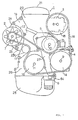
- Figure 1 is a front view of the engine with a cooling configuration not being an embodiment of the present invention,
- Figure 2 is a front view of the engine unit with the auxiliary equipment removed from the engine,
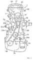
- Figure 3 is a front view of the engine in Figure 2 with the cover member (front cover) removed,
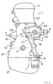
- Figure 4 is a sectional view of the engine along line A-A of Figure 2,
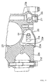
- Figure 5 is a sectional view of the water pump along line B-B of Figure 2,
- Figure 6 is a searon sectional view showing a part of the engine above the off cooler along line C-C of Figure 2.,
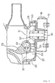
- Figure 7 is a sectional view of a part of the engine corresponding to Figure 6 but having an improved oil cooling arrangement as an embodiment of the present invention,
- Figure 8 is a Figure used to show the circulation of the coolant by the water pump shown in Figure 5,
- Figure 9 is a Figure used to show the configuration and mounting of the oil cooler affixed to the engine shown in Figure 1,
- Figure 10 is a bottom view showing the configuration and mounting of the oil cooler affixed to the engine shown in Figure 1,
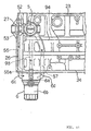
- Figure 11 is a side view showing the affixation of the cylinder block, crankcase and oil cooler at the front of the engine shown in Figure 1,
- Figure 12 is an exploded side view showing a part of the engine unit and the placement of the mounting bracket for the engine shown in Figure 1,
- Figure 13 is a sectional view of the oil pan showing the oil return passage to the oil pan and the blow-by gas passages on the engine shown in Figure 1,
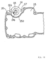
- Figure 14 is a sectional view of the oil pan showing another configuration the oil return passage to the oil pan and the blow-by gas passages on the engine shown in Figure 1,
- Figure 15 is a front view that corresponds to Figure 2 of an embodiment of the engine unit, not being an embodiment of the present invention, and
- Figure 16 is a front view that corresponds to Figure 2 of yet another embodiment, not according to the invention.
-
- An embodiment of the cooling configuration for engines according to the present invention will be described below with reference to Figure 7.
- Figure 1 shows a multi-cylinder four-cycle engine and the auxiliary equipment mounted around the engine unit when viewed from the front (in the crankshaft direction). Positioned around the
engine unit 1 are analternator 2, a power steering pump 3, an air conditioning compressor 4, and awater pump 5 which is located on the front surface of theengine unit 1. Anoil cooler 6 which holds an integral filter is located on the bottom of theengine unit 1. -
Pulleys various input shafts 7, 8, 9 and 10 of thealternator 2, the power steering pump 3, the air conditioning compressor 4, and thewater pump 5. In addition, apulley 16 is affixed to theoutput shaft 11 of the crankshaft, and asingle belt 18 spans atension pulley 17 and thevarious pulleys - Further, the
engine unit 1 is affixed to the vehicle by bolts which fasten it to the mounting bracket, and this mounting bracket is affixed to the top of thealternator 2. - As shown in Figure 12, this
mounting bracket 19 comprises an affixingmember 19e for attachment to the vehicle, and afastening member 19f which is affixed to the top of thealternator 2 andattachment bolts various parts engine unit 1, thereby affixing it across both thecylinder head 22 and thecylinder block 23, - Figure 2 shows the
engine unit 1 of Figure 1, but minus thevarious pulleys belt 18; thealternator 2, the power steering pump 3, the air conditioning compressor 4 and the mounting bracket 19 (but still with theoil cooler 6 and the water pump 5). - A
front cover 26 is affixed to theengine unit 1 composed of thecylinder head cover 21,cylinder head 22,cylinder block 23,crankcase 24, and theoil pan 25 which spans the front surfaces of both thecylinder block 23 and the crankcase 34. Further, thewater pump 5 and thecoolant passage 55, etc., are present in the surface of thefront cover 26, and a part of that is covered by an outer element. - In the present embodiment, the
cylinder block 23 and thecrankcase 24 are split into two members, but it would also be possible to have a monoblock construction wherein thecylinder block 23 and thecrankcase 24 are unifized. - Figure 3 shows the
engine unit 1 of Figure 2 with the outer element being additionally removed from thefront cover 26. In this Figure, the front surface of thecylinder block 23 comprises the water jacket opening 32 for the introduction of the coolant from thewater pump 5 into the water jacket of the cylinder block. The opening of theoil introduction passage 24a, which introduces oil pumped by the oil pump into theoil cooler 6, is located on the lower front surface of thecrankcase 24, which is positioned above theoil cooler 6. - Two
parallel sprockets chain 61 while the other engageschain 62, are affixed to theoutput shaft 11 of the crankshaft, which is located between thecylinder block 23 and thecrankcase 24. - The
chain 61 transmits the rotational drive of theoutput shaft 11 of the crankshaft to the airintake side camshaft 64 andexhaust camshaft 65 which services the three air intake valves and two exhaust valves in a five valve twin cam (not shown) configuration located in the top portion of the engine. It represents the lower chain in a two stage drive transmission system wherein an intermediate rotatingshaft 67 rotates thevarious camshafts upper chain 68. - The two chains used in this twin cam valve system may be externally adjusted for tension by the
tensioner 71 on thecylinder head 22 which serves the upper chain, and by thetensioner 72 on thecylinder block 23 which serves the lower chain. In order to secure the space required for locating thetensioners shaft 67 is offset from the centerline of the engine that passes through the cylinder axis toward the side of the engine that is opposite thetensioners -
Chain 62 transmits the rotation of theoutput shaft 11 of the crankshaft to theinput shaft 63 of an oil pump (not shown) located inside theoil pan 25 under the engine. - In the above described engine, the
attachment area 19f of themounting bracket 19 is secured to the attachment area 2a above thealternator 2 by a bolt, and thelower attachment area 2b is affixed to theattachment area 23d of an integrally formedalternator support member 23c, in a manner such that thealternator 2 is supported above and below with respect to theengine unit 1 as shown in Figure 1. - As shown in Figure 4, the
lower support member 23c for thealternator 2 is formed integrally as a projection from thecylinder block 23 in the width direction of the engine. Anattachment area 23d present in thesupport member 23c enables the alternator to be affixed at itslower attachment area 2b by a bolt. - Because the
alternator 2 is affixed to the engine unit by theattachment area 19f on the mountingbracket 19 and by thesupport member 23c of the cylinder block, the attachment to the engine at the lower attachment area is very strong, and since the upper attachment area 2a is affixed by the mountingbracket 19 to the vehicle body, the attachment condition is little affected by engine vibration. Further, should the specifications for thealternator 2 change, a different alternator could be used by merely changing to adifferent mounting bracket 19. - Located below the
support 23c for the alternator is thepush rod 72b,which applies pressure to thetension arm 72a of thetensioner 72 for thelower chain 61, and in order to allow thepush rod 72b to be adjusted from the outside, theattachment hole 23e for affixing thecylinder 72c to thepush rod 72b passes through thecylinder block 23. - As shown in Figure 13, an
oil return passage 81 opening into theoil pan 25 and a blow-bygas passage 82 are present in thecylinder block 23 and thecrankcase 24 of the foregoingengine unit 1. Apartition wall 25a in theoil pan 25 separates theopening area 81a of theoil return passage 81 in the crankcase from the inside of theoil pan 25 and protrudes from the floor of theoil pan 25. - A drain hole for removing the oil is also drilled into the bottom of the
oil pan 25 and a part of the bottom of thepartition wall 25a is therefore removed. Therefore, when closing the bottom drain hole from the outside with aplug 83, a connectingarea 84 to the extension of theoil return passage 81 is present at the bottom of the partition wall that connects to the inside of the oil pan. - By using this
partition wall 25a in the oil pan, and by forming the connectingarea 84 between theoil pan 25 and the extension of theoil return passage 81 at the bottom of thepartition wall 25, the level of the oil in the oil pan is such that when the engine is running, the liquid surface is L1 and when the engine is stopped the liquid surface is at L2, thereby assuring that the opening of theoil return passage 81 is always beneath the surface of the oil and that the oil remains unaffected by blow-by gases. This feature prevents oil from being blown upward, promotes better oil circulation, lowers the amount of air bubble intermixture in the returned oil, and improves its lubricating performance. - As shown in Figure 14, an
oil reservoir 25c is formed by thepartition wall 25b at some distance from theopening 81a of theoil return passage 81 in the crankcase in the area where the oil pan is shallow, and this feature ensures that theopening 81a of theoil return passage 81 always remains under the surface of the liquid in theoil reservoir 25c, thereby creating a siphon area with the connection hole to theopening 81a of the oil return area so that the oil return passage is always open under the surface of the oil unaffected by the blow-by gases. - As shown in Figure 2, with respect to the engine with the above described configuration, the surface of the
front cover 26 that covers the front surface of thecylinder block 23 and thecrankcase 24 is shaped to extend down toward theoil cooler 6 and is further covered by an outer element affixed by bolts. Thisfront cover 26 and outer element form theturbine housing 52 for thewater pump 5, thecoolant passage 54 to theopening 32 of the water jacket, and thecoolant passage 55 to the oil cooler in a manner such that they are integrated into the engine unit - To wit, as shown in Figure 5, the
front cover 26 and the outer element are configured to create theturbine housing 53 for thewater pump 5 and thecoolant passage 54 so that the connection opening 31 of the water pump connects to theopening 32 to the water jacket. - A
turbine 52 is located inside theturbine housing 53 of thewater pump 5, and the input shaft of theturbine 52 extends to the outside of the outer element, while apulley 15 is affixed to its end. The rotation of theoutput shaft 11 of the crankshaft drives thepulley 16, thebelt 18, thepulley 15, and theturbine 52 is rotated by theinput shaft 10 to drive thewater pump 5. - The
coolant passage 55 from thewater pump 5 to theoil cooler 6 extends downward as a branch from the middle of thecoolant passage 54 from theturbine housing 53 to thewater jacket opening 32. Therefore, just like theturbine housing 53 of thewater pump 5 and thecoolant passage 54, most of thecoolant passage 55 is present in thefront cover 26 and theouter element 27. As shown in Figures 6 and 11, after thelower end 55a of thecoolant passage 55 enters thefront cover 26, it connects with thecoolant inlet 6c of theoil cooler 6. - The
outer element 27 is affixed to the front surface of thefront cover 26 and extends in the transverse direction with respect to the engine. As shown in Figure 4, themating surfaces cylinder block 23 and the front cover lie in different planes in the transverse direction with respect to the engine (left and right in the Figure). The extent to which the outer element bulges from thefront cover 26 can be reduced because themating surface 23b is set farther back with respect to the side where the outer cover is affixed. - The
water pump 5 is connected to theoil cooler 6 by thecoolant passage 55, and as shown in Figure 9, the cooler 6a and thefilter 6b are jointly integrated inside and are located next to a concave area in the side wall of the oil pan and are directly affixed to the bottom surface of thecrankcase 24. - To wit, as shown in Figure 10, a
concave area 25d is present in the front surface of the oil pan and bends inward, so that when theoil pan 25 is affixed to thecrankcase 24, the lower surface of the crankcase and the lower surface of thefront cover 26 remain exposed in the area of theconcave indent 25d in theoil pan 25, whereby theoil cooler 6 can be directly affixed at this exposed area on the bottom surface of the crankcase by inserting it into theconcave area 25d from the outside of the oil pan. - Also present in the lower surface of the
crankcase 24 where theoil cooler 6 is affixed are several openings, anoil introduction area 24b of anoil introduction passage 24a that opens into the bottom front surface of thecrankcase 24, anoil passage 93 transmitting the oil upward from theoil cooler 6, and acoolant passage 57 returning coolant to the water pump. Thelower opening 55a of thecoolant passage 55 is located at the lower surface of thefront cover 26 where it meets the oil cooler . - Thus, the
water pump 5 pumps coolant to theoil cooler 6 directly affixed to the bottom surface of thecrankcase 24, and, as shown in Figure 1, the coolant passes through thecoolant passage 55 and into the coolant introduction opening 6c of the oil cooler at the lower surface of thefront cover 26 and cools the oil inside thecooler 6 that was transmitted therein by the oil pump. After the oil has been cooled, the coolant moves through thecoolant exit 6d of the oil cooler in the lower surface of thecrankcase 24, and continuing from thecoolant passage 57 present in thecrankcase 24 andcylinder block 23, it passes through the water pump connection opening 31 (thermostat chamber) and is returned to thewater pump 5. - On the other hand, the oil that is transmitted to the
oil cooler 6 by an oil pump (not shown), and as shown in Figure 6, is sent from theoil passage 91 present in thefront cover 26 to theoil introduction passage 24a present in the lower end of thecrankcase 24 and is fed into theoil cooler 6 from the lower surface of thecrankcase 24. As shown in Figure 11, inside the cooler 9a, the oil is cooled by coolant from thewater pump 5 and then passes through the filter 9b, through theoil passage 93, and upward through themain hole 94, from where it is supplied to various parts of the engine. - In the present embodiment, the
coolant passage 55 from thewater pump 5 to theoil cooler 6 is primarily present in the stock of thefront cover 26 and in the outer element, and a part of it denoted by 55a is formed in thefront cover 26 near its lower end. With regard to thiscoolant passage 55 from thewater pump 5 to the oil cooler 8, it is also possible to completely integrate thiscoolant passage 55 to theoil cooler 6 into thefront cover 26 as shown in Figure 15, or to form thecoolant passage 55 to theoil cooler 6 inside thecylinder block 23 and thecrankcase 24 as shown in Figure 16. - Furthermore, the embodiment, as shown in Figure 6, integrally configures the
oil passage 91 from the oil pump (not shown) to the oil introduction passage of thecrankcase 24 in the stock of thefront cover 26, but according to the invention, it is possible to employ a separate pipe from theoil pump 6 to theoil introduction passage 24a, which would connect to theoil introduction passage 24a at the bottom of thecrankcase 24, as shown in Figure 7. - The engine of this present embodiment, comprising the above described
water pump 5, theoil cooler 6, andcoolant passages water pump 5 on the front surface of theengine unit 1 in close proximity to theopening 32 to the water jacket of thecylinder block 23, thereby enabling efficient supply of coolant to the inside of thecylinder block 23, with the additional benefit of allowing thewater pump 5 to be more compactly installed on theengine unit 1. - The mating surfaces 23a, 23b between the
cylinder block 23 and thecrankcase 24 are present in different planes in the transverse direction with respect to the engine, and thewater pump 5 and thecoolant passages front cover 26 on the side where themating surface 23b is the more recessed, thereby much reducing the protrusion, from the front side of the engine, by thewater pump 5 and thecoolant passages cylinder block 23 and thefront cover 26 are present in the same plane. - Furthermore, the
pulley 15 on the input shaft of thewater pump 5 lies in approximately the same plane as thepulleys pulley 16 on theoutput shaft 11 of the crankshaft, thereby allowing efficient transmission of the crankshaft output by asingle belt 18 to thewater pump 5 as well as to the other auxiliary equipment mounted around the engine. - In addition, the
oil cooler 6 contains an integratedcooler member 6a andfilter member 6b which are affixed directly to the bottom surface of thecrankcase 24 outside theoil pan 25 using simple but compact assembly of the oil cooler and oil filter to the engine. Further, there is no need for piping between the oil cooler and oil filter, and it is easy to replace theoil cooler 6 alone, or only thefilter portion 6b. Theoil cooler 6, receiving oil from the oil pump and coolant from thewater pump 5, receives a matched supply of oil and coolant, which facilitates its efficient operation. - Further, the coolant supply passage located between the
water pump 5 and theoil cooler 6 is present in the stock of thefront cover 26 and the outer element, and thecoolant return passage 54 between theoil cooler 6 and thewater pump 5 is present in thecrankcase 24 andcylinder block 23 so that no special pipes or hoses are required for the coolant passages, thereby reducing the number of parts and simplifying the piping operations for the coolant passage. - The engine cooling configuration of this invention as described above utilizes the component stock for the cover member that covers the side surface of the engine for the water pump, thereby enabling the compact placement of the water pump on the side surface of the engine unit; further enabling efficient supply of coolant to the inside of the cylinder block due to the close proximity location of the water pump to the opening for the water jacket into the cylinder block; and again enabling the water pump to be efficiently driven along with the other auxiliary equipment by a single belt.
- Moreover, the attachment and maintenance operations of the oil cooler are simplified and efficient oil cooler operation is obtained by matching the supply of oil from the oil pump and coolant by the water pump to cool the oil cooler.
- The specific lubricating arrangement comprising the design as shown in greater detail in figures 13 and 14 can also be used independently from the cooling arrangement of the oil pump.
- Finally, the embodiments allow coolant passages to be used which eliminate the need for hoses, etc., thereby reducing the number of parts used and improving maintenance operations and properties as well as the life time of the coolant passage piping.
Claims (5)
- Internal combustion engine having an engine unit (1) comprising:a cylinder head cover (21), a cylinder block (23) including a crankcase structure (24), a water jacket, a cylinder head (22) attached to said cylinder block (23), and a crankcase (24), said engine further comprising a front cover (26) covering at least partially a front surface of said cylinder block (23), and auxiliary equipment including a coolant pump (5), driven from the engine by continuous drive means (61,62) arranged at the front side of said engine, a turbine housing (52) of said coolant pump (5) and at least one coolant connection passage way (54) to an opening (32) of said water jacket, characterized in that
said turbine housing (52) of said coolant pump (5), as well as said coolant connection passageway (54) and a coolant passage (55) to an oil cooler (6) are formed by said front cover (26) and an external member (27), attached to said front cover (26), such that said turbine housing (52), said coolant connection passageway (54) and said coolant passage (55) are integrated into the engine unit (1) and that a separate pipe (96) from an oil pump (6) leads to an oil introduction passage (24a), which is connected to the oil introduction passage (24a) at the bottom of the crankcase (24). - Internal combustion engine as claimed in claim 1, characterized in that said coolant passageway (55) extends further through the cylinder block (23) and the crankcase (24).
- Internal combustion engine as claimed in claim 1 or 2, characterized in that a drive pulley (15) affixed to an input end of a water pump drive shaft (10) is disposed in the same plane as various drive pulleys of the auxiliary equipment and that a single drive belt (18) is used spanning the drive pulleys of the auxiliary equipment including the water pump (5) and an output pulley (16) disposed at an output end of the crankshaft (11).
- Internal combustion engine as claimed in at least one of the preceding claims 1 to 3, characterized in that the water pump (5) is arranged in close proximity to an opening of a water jacket of the cylinder block (23).
- Internal combustion engine as claimed in at least one of the preceding claims 1 to 4, characterized in that an engine mounting bracket (19) is affixed to various parts of the cylinder head (22) and the cylinder block (23) and to a top of alternator (2) by means of attachment bolts (19a-d) and a fastening member (19f), said engine mounting bracket (19) comprising an affixing member (19a) for attachment to a vehicle.
Applications Claiming Priority (3)
| Application Number | Priority Date | Filing Date | Title |
|---|---|---|---|
| JP27062094A JP3287961B2 (en) | 1993-10-29 | 1994-10-07 | Engine cooling structure |
| JP270620/94 | 1994-10-07 | ||
| JP27062094 | 1994-10-07 |
Publications (3)
| Publication Number | Publication Date |
|---|---|
| EP0705964A2 EP0705964A2 (en) | 1996-04-10 |
| EP0705964A3 EP0705964A3 (en) | 1996-06-12 |
| EP0705964B1 true EP0705964B1 (en) | 2002-03-06 |
Family
ID=17488630
Family Applications (1)
| Application Number | Title | Priority Date | Filing Date |
|---|---|---|---|
| EP95115815A Expired - Lifetime EP0705964B1 (en) | 1994-10-07 | 1995-10-06 | Internal combustion engine |
Country Status (3)
| Country | Link |
|---|---|
| US (2) | US5647315A (en) |
| EP (1) | EP0705964B1 (en) |
| DE (1) | DE69525704T2 (en) |
Cited By (1)
| Publication number | Priority date | Publication date | Assignee | Title |
|---|---|---|---|---|
| DE102004056601B4 (en) * | 2004-11-24 | 2012-11-29 | Volkswagen Ag | Arrangement for sealing two assemblies for different media |
Families Citing this family (63)
| Publication number | Priority date | Publication date | Assignee | Title |
|---|---|---|---|---|
| JP3698800B2 (en) * | 1996-03-19 | 2005-09-21 | ヤマハ発動機株式会社 | Water vehicle engine mounting structure |
| JPH09309497A (en) * | 1996-05-25 | 1997-12-02 | Sanshin Ind Co Ltd | Cooling device for outboard motor |
| JPH09317426A (en) * | 1996-05-31 | 1997-12-09 | Yamaha Motor Co Ltd | Engine lubricator for small boats |
| DE19719199A1 (en) * | 1996-10-26 | 1998-04-30 | Knecht Filterwerke Gmbh | Cooling medium pump, especially for motor vehicle |
| JP3763910B2 (en) * | 1996-11-20 | 2006-04-05 | ヤマハマリン株式会社 | Lubricating oil supply device for outboard engine |
| JP3852723B2 (en) * | 1997-09-12 | 2006-12-06 | 本田技研工業株式会社 | Vertical internal combustion engine |
| JPH11159329A (en) * | 1997-11-28 | 1999-06-15 | Suzuki Motor Corp | Internal combustion engine cooling system |
| JP3999340B2 (en) * | 1997-12-10 | 2007-10-31 | ヤマハ発動機株式会社 | Cylinder block structure |
| JP3952234B2 (en) | 1998-04-13 | 2007-08-01 | ヤマハ発動機株式会社 | Lubricating oil cooling device for internal combustion engine for ships |
| DE19846586B4 (en) * | 1998-10-09 | 2009-07-09 | Audi Ag | Method for producing a composite housing |
| JP4017767B2 (en) | 1998-10-14 | 2007-12-05 | ヤマハマリン株式会社 | Engine lubrication oil supply device |
| DE19851232A1 (en) * | 1998-11-06 | 2000-05-11 | Bayerische Motoren Werke Ag | Cast machine housing for a forced-circulation internal combustion engine with a lubrication system, in particular with cylinders arranged in a row |
| US6416372B1 (en) | 1998-11-16 | 2002-07-09 | Sanshin Kogyo Kabushiki Kaisha | Outboard motor cooling system |
| US6058898A (en) * | 1998-12-28 | 2000-05-09 | Detroit Diesel Corporation | Structural oil pan with integrated oil filtration and cooling system |
| DE60013923T2 (en) | 1999-02-01 | 2005-01-27 | Honda Giken Kogyo K.K. | Ventilation device for a crankcase with a gas passage between crankcase parts |
| JP3668387B2 (en) * | 1999-02-22 | 2005-07-06 | 本田技研工業株式会社 | Chain case separator structure |
| GB2353561A (en) * | 1999-08-21 | 2001-02-28 | Cummins Engine Co Ltd | An engine block with machined end faces for receiving a camshaft gear train |
| JP2001107740A (en) | 1999-10-04 | 2001-04-17 | Sanshin Ind Co Ltd | Four-cycle engine |
| US6718935B2 (en) * | 2000-01-24 | 2004-04-13 | International Engine Intellectual Property Company, Llc | Hydraulic fuel system |
| US6554664B1 (en) | 2000-02-17 | 2003-04-29 | Yamaha Hatsudoki Kabushiki Kaisha | Cooling system for watercraft |
| DE10008692C2 (en) * | 2000-02-24 | 2002-03-14 | Ibs Filtran Kunststoff Metall | Oil pan for engines or transmissions |
| EP1195504B1 (en) * | 2000-10-03 | 2006-12-27 | Mazda Motor Corporation | Engine block structure for reciprocating engine |
| JP2002256836A (en) | 2001-02-28 | 2002-09-11 | Sanshin Ind Co Ltd | Oil tank cooling structure of small craft |
| JP2002256839A (en) | 2001-02-28 | 2002-09-11 | Sanshin Ind Co Ltd | Dry sump lubricating structure of small craft |
| JP2002276318A (en) | 2001-03-14 | 2002-09-25 | Yamaha Motor Co Ltd | Engine lubricator arrangement structure |
| KR100401914B1 (en) | 2001-06-25 | 2003-10-17 | 현대자동차주식회사 | Oil separator for blow by gas |
| US20050129680A1 (en) * | 2001-09-17 | 2005-06-16 | Paul Wentworth | Antimicrobial activity of antibodies |
| US20040157280A1 (en) * | 2001-09-17 | 2004-08-12 | Paul Wentworth | Antibody mediated ozone generation |
| US20040116350A1 (en) * | 2001-09-17 | 2004-06-17 | Paul Wentworth Jr | Methods and compositions relating to hydrogen peroxide and superoxide production by antibodies |
| JP2003117053A (en) * | 2001-10-12 | 2003-04-22 | Aruze Corp | Game server, game management method and game machine |
| AU2003216400A1 (en) | 2002-02-22 | 2003-09-09 | The Curators Of The University Of Missouri | Compounds for treatment of copper overload |
| JP2006506613A (en) * | 2002-11-14 | 2006-02-23 | ノバルティス アクチエンゲゼルシャフト | Ozone production via antibodies or neutrophils |
| DE10303102A1 (en) * | 2003-01-28 | 2004-07-29 | Deutz Ag | Internal combustion engine has cooling water pump module arranged at region of transition from front of engine to side wall with water channel with flow connection to oil cooler module |
| JP2004293347A (en) * | 2003-03-25 | 2004-10-21 | Yed:Kk | Lubricating device in engine |
| CN100378299C (en) * | 2003-03-25 | 2008-04-02 | 马来西亚国家石油公司 | Engine lubrication system |
| US6796283B1 (en) * | 2003-06-24 | 2004-09-28 | Ford Global Technologies, Llc | Oiling system for an internal combustion engine |
| KR20050005783A (en) * | 2003-07-07 | 2005-01-14 | 미쯔비시 지도샤 고교 가부시끼가이샤 | Cover of engine-power transmission apparatus |
| DE102004010799A1 (en) * | 2004-03-05 | 2005-09-22 | Fev Motorentechnik Gmbh | Water pump for an internal combustion engine |
| US20060054407A1 (en) * | 2004-07-20 | 2006-03-16 | Wirth Kirk L | Transmission lubrication system for towing and method |
| DE102004049030B4 (en) * | 2004-10-08 | 2008-09-11 | Audi Ag | Arrangement of a timing case cover |
| JP4452208B2 (en) * | 2005-04-18 | 2010-04-21 | 三菱重工業株式会社 | V-type engine oil filter mounting structure |
| US7204224B2 (en) * | 2005-09-13 | 2007-04-17 | Gm Global Technology Operations, Inc. | Engine block structure |
| US7621251B1 (en) | 2006-03-10 | 2009-11-24 | Polaris Industries Inc. | Lubrication cooling system for a vehicle |
| DE202006007446U1 (en) | 2006-05-10 | 2007-09-13 | Hengst Gmbh & Co.Kg | Oil module with integrated cooling water channel |
| US7992667B2 (en) * | 2006-08-08 | 2011-08-09 | David Wayne Rennie | Oil cooling and filtering system, kit and apparatus |
| JP5077686B2 (en) * | 2008-03-27 | 2012-11-21 | 本田技研工業株式会社 | Cooling device for internal combustion engine |
| SI22915A (en) * | 2008-11-04 | 2010-05-31 | CIMOS@d@d | Bracket of high-pressure pump for internal combustion engines |
| IT1391621B1 (en) * | 2008-11-05 | 2012-01-11 | Cnh Italia Spa | DRAINAGE TRAP FOR VEHICLES |
| JP5272941B2 (en) * | 2009-07-21 | 2013-08-28 | 株式会社Ihi | Turbo compressor and refrigerator |
| JP5636753B2 (en) * | 2010-06-15 | 2014-12-10 | 日産自動車株式会社 | Hybrid vehicle |
| US8911620B2 (en) * | 2010-11-29 | 2014-12-16 | Vesa S. Silegren | Universal spin-on oil filter adapter |
| US20130180496A1 (en) * | 2012-01-12 | 2013-07-18 | Chrysler Group Llc | Stepped oil-cooler |
| WO2013137043A1 (en) * | 2012-03-16 | 2013-09-19 | 愛知機械工業株式会社 | Structure for retaining temperature sensing device and internal combustion engine provided with same |
| KR102463186B1 (en) * | 2016-12-13 | 2022-11-03 | 현대자동차 주식회사 | Piston cooling apparatus for vehicle |
| JP6646569B2 (en) * | 2016-12-28 | 2020-02-14 | 株式会社クボタ | engine |
| US10550754B2 (en) | 2017-05-15 | 2020-02-04 | Polaris Industries Inc. | Engine |
| US10428705B2 (en) | 2017-05-15 | 2019-10-01 | Polaris Industries Inc. | Engine |
| US10520075B2 (en) * | 2017-05-31 | 2019-12-31 | Mahle International Gmbh | Apparatus for controlling the temperature of an oil cooler in a motor vehicle |
| USD904227S1 (en) | 2018-10-26 | 2020-12-08 | Polaris Industries Inc. | Headlight of a three-wheeled vehicle |
| US10934904B2 (en) * | 2019-07-03 | 2021-03-02 | Gale C. Banks, III | Lube oil aeration and thermal control system |
| IT202300014043A1 (en) * | 2023-07-05 | 2025-01-05 | Stellantis Europe Spa | INTERNAL COMBUSTION ENGINE FOR MOTOR VEHICLES |
| USD1072899S1 (en) | 2024-06-20 | 2025-04-29 | Gale C. Banks, III | Oil midpan |
| US12264606B1 (en) | 2024-10-31 | 2025-04-01 | Gale C. Banks, III | Oil pan with air return ports for directing airflow in internal combustion engines |
Family Cites Families (27)
| Publication number | Priority date | Publication date | Assignee | Title |
|---|---|---|---|---|
| US1024579A (en) * | 1911-08-07 | 1912-04-30 | Packard Motor Car Co | Crank-case. |
| US1281548A (en) * | 1918-04-08 | 1918-10-15 | Continental Motors Corp | Crank-case pan for engines. |
| US2063436A (en) * | 1931-02-24 | 1936-12-08 | Frederic W Hild | Multiflow cooling for internal combustion engines |
| US2440815A (en) * | 1944-01-14 | 1948-05-04 | Ford Motor Co | Crankcase construction |
| US2852009A (en) * | 1952-11-19 | 1958-09-16 | Gen Motors Corp | Cooling liquid circulating system for engines |
| DE960326C (en) * | 1953-01-07 | 1957-03-21 | Hovalwerk Ag Ospelt | Two-stroke internal combustion engine with cylinders arranged in a V shape |
| US3354988A (en) * | 1965-09-17 | 1967-11-28 | Gen Motors Corp | Engine with baffled oil pan |
| US4155333A (en) * | 1977-04-07 | 1979-05-22 | Brunswick Corporation | Centrifugal water pump for internal combustion engines |
| US4615314A (en) * | 1979-11-01 | 1986-10-07 | Cummins Engine Company, Inc. | Reversible oil pan assembly |
| US4387764A (en) * | 1981-12-03 | 1983-06-14 | Felt Products Mfg. Co. | Gasket screening assembly for an internal combustion engine having an auxiliary oil cooler |
| US4423708A (en) * | 1981-12-31 | 1984-01-03 | Cummins Engine Company, Inc. | Liquid cooling unit for an internal combustion engine |
| US4426965A (en) * | 1982-02-11 | 1984-01-24 | Cummins Engine Company, Inc. | Unitized oil cooler and filter assembly |
| US4892136A (en) * | 1986-12-31 | 1990-01-09 | Kabushiki Kaisha Tsuchiya Seisakusho | Heat exchanger |
| DE3831308C1 (en) * | 1988-09-15 | 1990-01-18 | Dr.Ing.H.C. F. Porsche Ag, 7000 Stuttgart, De | |
| JPH07111146B2 (en) * | 1989-02-08 | 1995-11-29 | 日産自動車株式会社 | Chain cover device for internal combustion engine |
| JPH02291405A (en) * | 1989-05-01 | 1990-12-03 | Nissan Motor Co Ltd | Camshaft driving device for dohc engine |
| JPH0343513U (en) * | 1989-09-07 | 1991-04-24 | ||
| JP2543655Y2 (en) * | 1990-03-30 | 1997-08-13 | マツダ株式会社 | Engine oil baffle plate fixing structure |
| JP2562842B2 (en) * | 1990-05-01 | 1996-12-11 | 日産自動車株式会社 | Chain chamber structure of internal combustion engine |
| US5014775A (en) * | 1990-05-15 | 1991-05-14 | Toyo Radiator Co., Ltd. | Oil cooler and manufacturing method thereof |
| JP2530308Y2 (en) * | 1990-06-05 | 1997-03-26 | マツダ株式会社 | Cooling water passage structure for V-type engine |
| US5107808A (en) * | 1991-04-15 | 1992-04-28 | Caterpillar Inc. | Reservoir assembly having a drain therein |
| DE4211896C2 (en) * | 1992-04-09 | 1994-07-28 | Daimler Benz Ag | Housing cover for an internal combustion engine |
| US5363823A (en) * | 1993-07-02 | 1994-11-15 | Michael Gittlein | Oil cooler |
| EP0651141B1 (en) * | 1993-10-29 | 1998-07-29 | Yamaha Hatsudoki Kabushiki Kaisha | Four-cycle engine |
| CA2113519C (en) * | 1994-01-14 | 1999-06-08 | Allan K. So | Passive by-pass for heat exchangers |
| US5601060A (en) * | 1996-03-26 | 1997-02-11 | Navistar International Transportation Corp. | Cast oil pan for internal combustion engine |
-
1995
- 1995-10-04 US US08/539,124 patent/US5647315A/en not_active Expired - Lifetime
- 1995-10-06 EP EP95115815A patent/EP0705964B1/en not_active Expired - Lifetime
- 1995-10-06 DE DE69525704T patent/DE69525704T2/en not_active Expired - Fee Related
-
1997
- 1997-01-24 US US08/786,759 patent/US5809963A/en not_active Expired - Fee Related
Cited By (1)
| Publication number | Priority date | Publication date | Assignee | Title |
|---|---|---|---|---|
| DE102004056601B4 (en) * | 2004-11-24 | 2012-11-29 | Volkswagen Ag | Arrangement for sealing two assemblies for different media |
Also Published As
| Publication number | Publication date |
|---|---|
| EP0705964A3 (en) | 1996-06-12 |
| US5647315A (en) | 1997-07-15 |
| DE69525704T2 (en) | 2002-08-01 |
| EP0705964A2 (en) | 1996-04-10 |
| DE69525704D1 (en) | 2002-04-11 |
| US5809963A (en) | 1998-09-22 |
Similar Documents
| Publication | Publication Date | Title |
|---|---|---|
| EP0705964A2 (en) | Internal combustion engine | |
| US5718196A (en) | Lubrication and camshaft control system for engine | |
| US6530356B2 (en) | Engine block structure for reciprocating engine | |
| US5503117A (en) | Engine cooling system | |
| CN100497899C (en) | Outboard motor equiped with water-cooled engine | |
| US6260533B1 (en) | Oil passageway structure for internal combustion engine | |
| US5078106A (en) | V-type engine lubrication system | |
| US6223709B1 (en) | Four cycle engine | |
| US6332441B1 (en) | Assembling arrangement for tensioner and hydraulic control valve | |
| EP0704605B1 (en) | Internal combustion engine with a cam phase variation apparatus | |
| JP3287961B2 (en) | Engine cooling structure | |
| JP4505984B2 (en) | Lubrication structure for valve gear of internal combustion engine | |
| US6182625B1 (en) | Oil-passage structure of internal combustion engine | |
| US4448159A (en) | V-Type internal combustion engine | |
| EP0651141B1 (en) | Four-cycle engine | |
| EP1398471A1 (en) | Water-cooled vertical engine and outboard motor equipped therewith | |
| CN100497898C (en) | Water-cooled engine, outboard motor equiped with water-cooled engine, and outboard motor | |
| CN100497897C (en) | Water cooled vertical engine and outboard motor equiped with the water-cooled vertical engine | |
| US6948471B1 (en) | Engine lubricating system | |
| CN100497900C (en) | Outboard motor | |
| US6179582B1 (en) | Oil pump attachment structure for engine | |
| JP2006226272A (en) | Internal combustion engine | |
| CN100378299C (en) | Engine lubrication system | |
| CN100390428C (en) | Drive system attached to the engine | |
| CN100564826C (en) | Water-cooled vertical engine and outboard motor equipped with the same |
Legal Events
| Date | Code | Title | Description |
|---|---|---|---|
| PUAI | Public reference made under article 153(3) epc to a published international application that has entered the european phase |
Free format text: ORIGINAL CODE: 0009012 |
|
| AK | Designated contracting states |
Kind code of ref document: A2 Designated state(s): DE FR GB IT |
|
| PUAL | Search report despatched |
Free format text: ORIGINAL CODE: 0009013 |
|
| AK | Designated contracting states |
Kind code of ref document: A3 Designated state(s): DE FR GB IT |
|
| 17P | Request for examination filed |
Effective date: 19961211 |
|
| 17Q | First examination report despatched |
Effective date: 19980916 |
|
| GRAG | Despatch of communication of intention to grant |
Free format text: ORIGINAL CODE: EPIDOS AGRA |
|
| GRAG | Despatch of communication of intention to grant |
Free format text: ORIGINAL CODE: EPIDOS AGRA |
|
| GRAH | Despatch of communication of intention to grant a patent |
Free format text: ORIGINAL CODE: EPIDOS IGRA |
|
| GRAH | Despatch of communication of intention to grant a patent |
Free format text: ORIGINAL CODE: EPIDOS IGRA |
|
| REG | Reference to a national code |
Ref country code: GB Ref legal event code: IF02 |
|
| GRAA | (expected) grant |
Free format text: ORIGINAL CODE: 0009210 |
|
| AK | Designated contracting states |
Kind code of ref document: B1 Designated state(s): DE FR GB IT |
|
| REF | Corresponds to: |
Ref document number: 69525704 Country of ref document: DE Date of ref document: 20020411 |
|
| ET | Fr: translation filed | ||
| PLBE | No opposition filed within time limit |
Free format text: ORIGINAL CODE: 0009261 |
|
| STAA | Information on the status of an ep patent application or granted ep patent |
Free format text: STATUS: NO OPPOSITION FILED WITHIN TIME LIMIT |
|
| 26N | No opposition filed |
Effective date: 20021209 |
|
| PGFP | Annual fee paid to national office [announced via postgrant information from national office to epo] |
Ref country code: FR Payment date: 20051010 Year of fee payment: 11 |
|
| PGFP | Annual fee paid to national office [announced via postgrant information from national office to epo] |
Ref country code: IT Payment date: 20061031 Year of fee payment: 12 |
|
| REG | Reference to a national code |
Ref country code: FR Ref legal event code: ST Effective date: 20070629 |
|
| PG25 | Lapsed in a contracting state [announced via postgrant information from national office to epo] |
Ref country code: FR Free format text: LAPSE BECAUSE OF NON-PAYMENT OF DUE FEES Effective date: 20061031 |
|
| PGFP | Annual fee paid to national office [announced via postgrant information from national office to epo] |
Ref country code: DE Payment date: 20081014 Year of fee payment: 14 |
|
| PGFP | Annual fee paid to national office [announced via postgrant information from national office to epo] |
Ref country code: GB Payment date: 20081001 Year of fee payment: 14 |
|
| PG25 | Lapsed in a contracting state [announced via postgrant information from national office to epo] |
Ref country code: IT Free format text: LAPSE BECAUSE OF NON-PAYMENT OF DUE FEES Effective date: 20071006 |
|
| PG25 | Lapsed in a contracting state [announced via postgrant information from national office to epo] |
Ref country code: DE Free format text: LAPSE BECAUSE OF NON-PAYMENT OF DUE FEES Effective date: 20100501 |
|
| PG25 | Lapsed in a contracting state [announced via postgrant information from national office to epo] |
Ref country code: GB Free format text: LAPSE BECAUSE OF NON-PAYMENT OF DUE FEES Effective date: 20091006 |