EP0705912A2 - A coated article - Google Patents
A coated article Download PDFInfo
- Publication number
- EP0705912A2 EP0705912A2 EP95112194A EP95112194A EP0705912A2 EP 0705912 A2 EP0705912 A2 EP 0705912A2 EP 95112194 A EP95112194 A EP 95112194A EP 95112194 A EP95112194 A EP 95112194A EP 0705912 A2 EP0705912 A2 EP 0705912A2
- Authority
- EP
- European Patent Office
- Prior art keywords
- coating
- thermal barrier
- ceramic
- bond
- barrier coating
- Prior art date
- Legal status (The legal status is an assumption and is not a legal conclusion. Google has not performed a legal analysis and makes no representation as to the accuracy of the status listed.)
- Granted
Links
- 238000000576 coating method Methods 0.000 claims abstract description 175
- 239000011248 coating agent Substances 0.000 claims abstract description 174
- 239000012720 thermal barrier coating Substances 0.000 claims abstract description 113
- 239000000758 substrate Substances 0.000 claims abstract description 62
- 229910000951 Aluminide Inorganic materials 0.000 claims abstract description 44
- PNEYBMLMFCGWSK-UHFFFAOYSA-N aluminium oxide Inorganic materials [O-2].[O-2].[O-2].[Al+3].[Al+3] PNEYBMLMFCGWSK-UHFFFAOYSA-N 0.000 claims abstract description 18
- 229910000601 superalloy Inorganic materials 0.000 claims abstract description 10
- 238000000034 method Methods 0.000 claims description 50
- BASFCYQUMIYNBI-UHFFFAOYSA-N platinum Chemical compound [Pt] BASFCYQUMIYNBI-UHFFFAOYSA-N 0.000 claims description 34
- 238000000151 deposition Methods 0.000 claims description 21
- 229910052697 platinum Inorganic materials 0.000 claims description 17
- MCMNRKCIXSYSNV-UHFFFAOYSA-N Zirconium dioxide Chemical compound O=[Zr]=O MCMNRKCIXSYSNV-UHFFFAOYSA-N 0.000 claims description 14
- 230000008021 deposition Effects 0.000 claims description 11
- 239000000203 mixture Substances 0.000 claims description 10
- RUDFQVOCFDJEEF-UHFFFAOYSA-N yttrium(III) oxide Inorganic materials [O-2].[O-2].[O-2].[Y+3].[Y+3] RUDFQVOCFDJEEF-UHFFFAOYSA-N 0.000 claims description 8
- 238000004519 manufacturing process Methods 0.000 claims description 5
- 239000004411 aluminium Substances 0.000 abstract description 2
- 229910052782 aluminium Inorganic materials 0.000 abstract description 2
- XAGFODPZIPBFFR-UHFFFAOYSA-N aluminium Chemical compound [Al] XAGFODPZIPBFFR-UHFFFAOYSA-N 0.000 abstract description 2
- 239000000919 ceramic Substances 0.000 description 116
- 238000005240 physical vapour deposition Methods 0.000 description 62
- 210000002381 plasma Anatomy 0.000 description 36
- 230000008569 process Effects 0.000 description 33
- XKRFYHLGVUSROY-UHFFFAOYSA-N Argon Chemical compound [Ar] XKRFYHLGVUSROY-UHFFFAOYSA-N 0.000 description 15
- 239000007789 gas Substances 0.000 description 9
- PXHVJJICTQNCMI-UHFFFAOYSA-N Nickel Chemical compound [Ni] PXHVJJICTQNCMI-UHFFFAOYSA-N 0.000 description 8
- 229910052786 argon Inorganic materials 0.000 description 8
- 238000010894 electron beam technology Methods 0.000 description 8
- 239000001257 hydrogen Substances 0.000 description 7
- 229910052739 hydrogen Inorganic materials 0.000 description 7
- QVGXLLKOCUKJST-UHFFFAOYSA-N atomic oxygen Chemical compound [O] QVGXLLKOCUKJST-UHFFFAOYSA-N 0.000 description 6
- 239000001301 oxygen Substances 0.000 description 6
- 229910052760 oxygen Inorganic materials 0.000 description 6
- 230000003628 erosive effect Effects 0.000 description 5
- 238000007751 thermal spraying Methods 0.000 description 5
- 239000000356 contaminant Substances 0.000 description 4
- 239000011261 inert gas Substances 0.000 description 4
- 229910052751 metal Inorganic materials 0.000 description 4
- 229910052759 nickel Inorganic materials 0.000 description 4
- VVTSZOCINPYFDP-UHFFFAOYSA-N [O].[Ar] Chemical compound [O].[Ar] VVTSZOCINPYFDP-UHFFFAOYSA-N 0.000 description 3
- 230000008901 benefit Effects 0.000 description 3
- 230000008020 evaporation Effects 0.000 description 3
- 238000001704 evaporation Methods 0.000 description 3
- 239000002184 metal Substances 0.000 description 3
- 230000009471 action Effects 0.000 description 2
- -1 argon ions Chemical class 0.000 description 2
- 238000005229 chemical vapour deposition Methods 0.000 description 2
- 238000005566 electron beam evaporation Methods 0.000 description 2
- 238000002474 experimental method Methods 0.000 description 2
- 150000002431 hydrogen Chemical class 0.000 description 2
- 230000001771 impaired effect Effects 0.000 description 2
- 239000000463 material Substances 0.000 description 2
- 238000007750 plasma spraying Methods 0.000 description 2
- 239000007921 spray Substances 0.000 description 2
- 241000588731 Hafnia Species 0.000 description 1
- 229910018487 Ni—Cr Inorganic materials 0.000 description 1
- 229910045601 alloy Inorganic materials 0.000 description 1
- 239000000956 alloy Substances 0.000 description 1
- 239000011449 brick Substances 0.000 description 1
- 238000005524 ceramic coating Methods 0.000 description 1
- 229910010293 ceramic material Inorganic materials 0.000 description 1
- CETPSERCERDGAM-UHFFFAOYSA-N ceric oxide Chemical compound O=[Ce]=O CETPSERCERDGAM-UHFFFAOYSA-N 0.000 description 1
- 229910000422 cerium(IV) oxide Inorganic materials 0.000 description 1
- VNNRSPGTAMTISX-UHFFFAOYSA-N chromium nickel Chemical compound [Cr].[Ni] VNNRSPGTAMTISX-UHFFFAOYSA-N 0.000 description 1
- 238000004140 cleaning Methods 0.000 description 1
- 238000000280 densification Methods 0.000 description 1
- 239000000284 extract Substances 0.000 description 1
- CJNBYAVZURUTKZ-UHFFFAOYSA-N hafnium(IV) oxide Inorganic materials O=[Hf]=O CJNBYAVZURUTKZ-UHFFFAOYSA-N 0.000 description 1
- 238000007733 ion plating Methods 0.000 description 1
- 238000001000 micrograph Methods 0.000 description 1
- 230000004048 modification Effects 0.000 description 1
- 238000012986 modification Methods 0.000 description 1
- 230000007935 neutral effect Effects 0.000 description 1
- 230000003647 oxidation Effects 0.000 description 1
- 238000007254 oxidation reaction Methods 0.000 description 1
- 238000000623 plasma-assisted chemical vapour deposition Methods 0.000 description 1
- 238000001878 scanning electron micrograph Methods 0.000 description 1
- 230000035939 shock Effects 0.000 description 1
- 238000004544 sputter deposition Methods 0.000 description 1
Images




Classifications
-
- C—CHEMISTRY; METALLURGY
- C23—COATING METALLIC MATERIAL; COATING MATERIAL WITH METALLIC MATERIAL; CHEMICAL SURFACE TREATMENT; DIFFUSION TREATMENT OF METALLIC MATERIAL; COATING BY VACUUM EVAPORATION, BY SPUTTERING, BY ION IMPLANTATION OR BY CHEMICAL VAPOUR DEPOSITION, IN GENERAL; INHIBITING CORROSION OF METALLIC MATERIAL OR INCRUSTATION IN GENERAL
- C23C—COATING METALLIC MATERIAL; COATING MATERIAL WITH METALLIC MATERIAL; SURFACE TREATMENT OF METALLIC MATERIAL BY DIFFUSION INTO THE SURFACE, BY CHEMICAL CONVERSION OR SUBSTITUTION; COATING BY VACUUM EVAPORATION, BY SPUTTERING, BY ION IMPLANTATION OR BY CHEMICAL VAPOUR DEPOSITION, IN GENERAL
- C23C28/00—Coating for obtaining at least two superposed coatings either by methods not provided for in a single one of groups C23C2/00 - C23C26/00 or by combinations of methods provided for in subclasses C23C and C25C or C25D
- C23C28/30—Coatings combining at least one metallic layer and at least one inorganic non-metallic layer
- C23C28/32—Coatings combining at least one metallic layer and at least one inorganic non-metallic layer including at least one pure metallic layer
- C23C28/321—Coatings combining at least one metallic layer and at least one inorganic non-metallic layer including at least one pure metallic layer with at least one metal alloy layer
- C23C28/3215—Coatings combining at least one metallic layer and at least one inorganic non-metallic layer including at least one pure metallic layer with at least one metal alloy layer at least one MCrAlX layer
-
- C—CHEMISTRY; METALLURGY
- C23—COATING METALLIC MATERIAL; COATING MATERIAL WITH METALLIC MATERIAL; CHEMICAL SURFACE TREATMENT; DIFFUSION TREATMENT OF METALLIC MATERIAL; COATING BY VACUUM EVAPORATION, BY SPUTTERING, BY ION IMPLANTATION OR BY CHEMICAL VAPOUR DEPOSITION, IN GENERAL; INHIBITING CORROSION OF METALLIC MATERIAL OR INCRUSTATION IN GENERAL
- C23C—COATING METALLIC MATERIAL; COATING MATERIAL WITH METALLIC MATERIAL; SURFACE TREATMENT OF METALLIC MATERIAL BY DIFFUSION INTO THE SURFACE, BY CHEMICAL CONVERSION OR SUBSTITUTION; COATING BY VACUUM EVAPORATION, BY SPUTTERING, BY ION IMPLANTATION OR BY CHEMICAL VAPOUR DEPOSITION, IN GENERAL
- C23C10/00—Solid state diffusion of only metal elements or silicon into metallic material surfaces
- C23C10/28—Solid state diffusion of only metal elements or silicon into metallic material surfaces using solids, e.g. powders, pastes
- C23C10/34—Embedding in a powder mixture, i.e. pack cementation
- C23C10/36—Embedding in a powder mixture, i.e. pack cementation only one element being diffused
- C23C10/48—Aluminising
-
- C—CHEMISTRY; METALLURGY
- C23—COATING METALLIC MATERIAL; COATING MATERIAL WITH METALLIC MATERIAL; CHEMICAL SURFACE TREATMENT; DIFFUSION TREATMENT OF METALLIC MATERIAL; COATING BY VACUUM EVAPORATION, BY SPUTTERING, BY ION IMPLANTATION OR BY CHEMICAL VAPOUR DEPOSITION, IN GENERAL; INHIBITING CORROSION OF METALLIC MATERIAL OR INCRUSTATION IN GENERAL
- C23C—COATING METALLIC MATERIAL; COATING MATERIAL WITH METALLIC MATERIAL; SURFACE TREATMENT OF METALLIC MATERIAL BY DIFFUSION INTO THE SURFACE, BY CHEMICAL CONVERSION OR SUBSTITUTION; COATING BY VACUUM EVAPORATION, BY SPUTTERING, BY ION IMPLANTATION OR BY CHEMICAL VAPOUR DEPOSITION, IN GENERAL
- C23C14/00—Coating by vacuum evaporation, by sputtering or by ion implantation of the coating forming material
- C23C14/02—Pretreatment of the material to be coated
-
- C—CHEMISTRY; METALLURGY
- C23—COATING METALLIC MATERIAL; COATING MATERIAL WITH METALLIC MATERIAL; CHEMICAL SURFACE TREATMENT; DIFFUSION TREATMENT OF METALLIC MATERIAL; COATING BY VACUUM EVAPORATION, BY SPUTTERING, BY ION IMPLANTATION OR BY CHEMICAL VAPOUR DEPOSITION, IN GENERAL; INHIBITING CORROSION OF METALLIC MATERIAL OR INCRUSTATION IN GENERAL
- C23C—COATING METALLIC MATERIAL; COATING MATERIAL WITH METALLIC MATERIAL; SURFACE TREATMENT OF METALLIC MATERIAL BY DIFFUSION INTO THE SURFACE, BY CHEMICAL CONVERSION OR SUBSTITUTION; COATING BY VACUUM EVAPORATION, BY SPUTTERING, BY ION IMPLANTATION OR BY CHEMICAL VAPOUR DEPOSITION, IN GENERAL
- C23C14/00—Coating by vacuum evaporation, by sputtering or by ion implantation of the coating forming material
- C23C14/02—Pretreatment of the material to be coated
- C23C14/024—Deposition of sublayers, e.g. to promote adhesion of the coating
- C23C14/025—Metallic sublayers
-
- C—CHEMISTRY; METALLURGY
- C23—COATING METALLIC MATERIAL; COATING MATERIAL WITH METALLIC MATERIAL; CHEMICAL SURFACE TREATMENT; DIFFUSION TREATMENT OF METALLIC MATERIAL; COATING BY VACUUM EVAPORATION, BY SPUTTERING, BY ION IMPLANTATION OR BY CHEMICAL VAPOUR DEPOSITION, IN GENERAL; INHIBITING CORROSION OF METALLIC MATERIAL OR INCRUSTATION IN GENERAL
- C23C—COATING METALLIC MATERIAL; COATING MATERIAL WITH METALLIC MATERIAL; SURFACE TREATMENT OF METALLIC MATERIAL BY DIFFUSION INTO THE SURFACE, BY CHEMICAL CONVERSION OR SUBSTITUTION; COATING BY VACUUM EVAPORATION, BY SPUTTERING, BY ION IMPLANTATION OR BY CHEMICAL VAPOUR DEPOSITION, IN GENERAL
- C23C14/00—Coating by vacuum evaporation, by sputtering or by ion implantation of the coating forming material
- C23C14/06—Coating by vacuum evaporation, by sputtering or by ion implantation of the coating forming material characterised by the coating material
- C23C14/08—Oxides
- C23C14/083—Oxides of refractory metals or yttrium
-
- C—CHEMISTRY; METALLURGY
- C23—COATING METALLIC MATERIAL; COATING MATERIAL WITH METALLIC MATERIAL; CHEMICAL SURFACE TREATMENT; DIFFUSION TREATMENT OF METALLIC MATERIAL; COATING BY VACUUM EVAPORATION, BY SPUTTERING, BY ION IMPLANTATION OR BY CHEMICAL VAPOUR DEPOSITION, IN GENERAL; INHIBITING CORROSION OF METALLIC MATERIAL OR INCRUSTATION IN GENERAL
- C23C—COATING METALLIC MATERIAL; COATING MATERIAL WITH METALLIC MATERIAL; SURFACE TREATMENT OF METALLIC MATERIAL BY DIFFUSION INTO THE SURFACE, BY CHEMICAL CONVERSION OR SUBSTITUTION; COATING BY VACUUM EVAPORATION, BY SPUTTERING, BY ION IMPLANTATION OR BY CHEMICAL VAPOUR DEPOSITION, IN GENERAL
- C23C14/00—Coating by vacuum evaporation, by sputtering or by ion implantation of the coating forming material
- C23C14/22—Coating by vacuum evaporation, by sputtering or by ion implantation of the coating forming material characterised by the process of coating
- C23C14/24—Vacuum evaporation
- C23C14/32—Vacuum evaporation by explosion; by evaporation and subsequent ionisation of the vapours, e.g. ion-plating
-
- C—CHEMISTRY; METALLURGY
- C23—COATING METALLIC MATERIAL; COATING MATERIAL WITH METALLIC MATERIAL; CHEMICAL SURFACE TREATMENT; DIFFUSION TREATMENT OF METALLIC MATERIAL; COATING BY VACUUM EVAPORATION, BY SPUTTERING, BY ION IMPLANTATION OR BY CHEMICAL VAPOUR DEPOSITION, IN GENERAL; INHIBITING CORROSION OF METALLIC MATERIAL OR INCRUSTATION IN GENERAL
- C23C—COATING METALLIC MATERIAL; COATING MATERIAL WITH METALLIC MATERIAL; SURFACE TREATMENT OF METALLIC MATERIAL BY DIFFUSION INTO THE SURFACE, BY CHEMICAL CONVERSION OR SUBSTITUTION; COATING BY VACUUM EVAPORATION, BY SPUTTERING, BY ION IMPLANTATION OR BY CHEMICAL VAPOUR DEPOSITION, IN GENERAL
- C23C28/00—Coating for obtaining at least two superposed coatings either by methods not provided for in a single one of groups C23C2/00 - C23C26/00 or by combinations of methods provided for in subclasses C23C and C25C or C25D
-
- C—CHEMISTRY; METALLURGY
- C23—COATING METALLIC MATERIAL; COATING MATERIAL WITH METALLIC MATERIAL; CHEMICAL SURFACE TREATMENT; DIFFUSION TREATMENT OF METALLIC MATERIAL; COATING BY VACUUM EVAPORATION, BY SPUTTERING, BY ION IMPLANTATION OR BY CHEMICAL VAPOUR DEPOSITION, IN GENERAL; INHIBITING CORROSION OF METALLIC MATERIAL OR INCRUSTATION IN GENERAL
- C23C—COATING METALLIC MATERIAL; COATING MATERIAL WITH METALLIC MATERIAL; SURFACE TREATMENT OF METALLIC MATERIAL BY DIFFUSION INTO THE SURFACE, BY CHEMICAL CONVERSION OR SUBSTITUTION; COATING BY VACUUM EVAPORATION, BY SPUTTERING, BY ION IMPLANTATION OR BY CHEMICAL VAPOUR DEPOSITION, IN GENERAL
- C23C28/00—Coating for obtaining at least two superposed coatings either by methods not provided for in a single one of groups C23C2/00 - C23C26/00 or by combinations of methods provided for in subclasses C23C and C25C or C25D
- C23C28/30—Coatings combining at least one metallic layer and at least one inorganic non-metallic layer
- C23C28/34—Coatings combining at least one metallic layer and at least one inorganic non-metallic layer including at least one inorganic non-metallic material layer, e.g. metal carbide, nitride, boride, silicide layer and their mixtures, enamels, phosphates and sulphates
- C23C28/345—Coatings combining at least one metallic layer and at least one inorganic non-metallic layer including at least one inorganic non-metallic material layer, e.g. metal carbide, nitride, boride, silicide layer and their mixtures, enamels, phosphates and sulphates with at least one oxide layer
-
- C—CHEMISTRY; METALLURGY
- C23—COATING METALLIC MATERIAL; COATING MATERIAL WITH METALLIC MATERIAL; CHEMICAL SURFACE TREATMENT; DIFFUSION TREATMENT OF METALLIC MATERIAL; COATING BY VACUUM EVAPORATION, BY SPUTTERING, BY ION IMPLANTATION OR BY CHEMICAL VAPOUR DEPOSITION, IN GENERAL; INHIBITING CORROSION OF METALLIC MATERIAL OR INCRUSTATION IN GENERAL
- C23C—COATING METALLIC MATERIAL; COATING MATERIAL WITH METALLIC MATERIAL; SURFACE TREATMENT OF METALLIC MATERIAL BY DIFFUSION INTO THE SURFACE, BY CHEMICAL CONVERSION OR SUBSTITUTION; COATING BY VACUUM EVAPORATION, BY SPUTTERING, BY ION IMPLANTATION OR BY CHEMICAL VAPOUR DEPOSITION, IN GENERAL
- C23C28/00—Coating for obtaining at least two superposed coatings either by methods not provided for in a single one of groups C23C2/00 - C23C26/00 or by combinations of methods provided for in subclasses C23C and C25C or C25D
- C23C28/30—Coatings combining at least one metallic layer and at least one inorganic non-metallic layer
- C23C28/34—Coatings combining at least one metallic layer and at least one inorganic non-metallic layer including at least one inorganic non-metallic material layer, e.g. metal carbide, nitride, boride, silicide layer and their mixtures, enamels, phosphates and sulphates
- C23C28/345—Coatings combining at least one metallic layer and at least one inorganic non-metallic layer including at least one inorganic non-metallic material layer, e.g. metal carbide, nitride, boride, silicide layer and their mixtures, enamels, phosphates and sulphates with at least one oxide layer
- C23C28/3455—Coatings combining at least one metallic layer and at least one inorganic non-metallic layer including at least one inorganic non-metallic material layer, e.g. metal carbide, nitride, boride, silicide layer and their mixtures, enamels, phosphates and sulphates with at least one oxide layer with a refractory ceramic layer, e.g. refractory metal oxide, ZrO2, rare earth oxides or a thermal barrier system comprising at least one refractory oxide layer
-
- F—MECHANICAL ENGINEERING; LIGHTING; HEATING; WEAPONS; BLASTING
- F01—MACHINES OR ENGINES IN GENERAL; ENGINE PLANTS IN GENERAL; STEAM ENGINES
- F01D—NON-POSITIVE DISPLACEMENT MACHINES OR ENGINES, e.g. STEAM TURBINES
- F01D5/00—Blades; Blade-carrying members; Heating, heat-insulating, cooling or antivibration means on the blades or the members
- F01D5/12—Blades
- F01D5/28—Selecting particular materials; Particular measures relating thereto; Measures against erosion or corrosion
- F01D5/288—Protective coatings for blades
-
- F—MECHANICAL ENGINEERING; LIGHTING; HEATING; WEAPONS; BLASTING
- F05—INDEXING SCHEMES RELATING TO ENGINES OR PUMPS IN VARIOUS SUBCLASSES OF CLASSES F01-F04
- F05D—INDEXING SCHEME FOR ASPECTS RELATING TO NON-POSITIVE-DISPLACEMENT MACHINES OR ENGINES, GAS-TURBINES OR JET-PROPULSION PLANTS
- F05D2260/00—Function
- F05D2260/20—Heat transfer, e.g. cooling
-
- F—MECHANICAL ENGINEERING; LIGHTING; HEATING; WEAPONS; BLASTING
- F05—INDEXING SCHEMES RELATING TO ENGINES OR PUMPS IN VARIOUS SUBCLASSES OF CLASSES F01-F04
- F05D—INDEXING SCHEME FOR ASPECTS RELATING TO NON-POSITIVE-DISPLACEMENT MACHINES OR ENGINES, GAS-TURBINES OR JET-PROPULSION PLANTS
- F05D2300/00—Materials; Properties thereof
- F05D2300/50—Intrinsic material properties or characteristics
- F05D2300/502—Thermal properties
- F05D2300/5024—Heat conductivity
-
- Y—GENERAL TAGGING OF NEW TECHNOLOGICAL DEVELOPMENTS; GENERAL TAGGING OF CROSS-SECTIONAL TECHNOLOGIES SPANNING OVER SEVERAL SECTIONS OF THE IPC; TECHNICAL SUBJECTS COVERED BY FORMER USPC CROSS-REFERENCE ART COLLECTIONS [XRACs] AND DIGESTS
- Y10—TECHNICAL SUBJECTS COVERED BY FORMER USPC
- Y10T—TECHNICAL SUBJECTS COVERED BY FORMER US CLASSIFICATION
- Y10T428/00—Stock material or miscellaneous articles
- Y10T428/12—All metal or with adjacent metals
- Y10T428/12493—Composite; i.e., plural, adjacent, spatially distinct metal components [e.g., layers, joint, etc.]
-
- Y—GENERAL TAGGING OF NEW TECHNOLOGICAL DEVELOPMENTS; GENERAL TAGGING OF CROSS-SECTIONAL TECHNOLOGIES SPANNING OVER SEVERAL SECTIONS OF THE IPC; TECHNICAL SUBJECTS COVERED BY FORMER USPC CROSS-REFERENCE ART COLLECTIONS [XRACs] AND DIGESTS
- Y10—TECHNICAL SUBJECTS COVERED BY FORMER USPC
- Y10T—TECHNICAL SUBJECTS COVERED BY FORMER US CLASSIFICATION
- Y10T428/00—Stock material or miscellaneous articles
- Y10T428/12—All metal or with adjacent metals
- Y10T428/12493—Composite; i.e., plural, adjacent, spatially distinct metal components [e.g., layers, joint, etc.]
- Y10T428/12535—Composite; i.e., plural, adjacent, spatially distinct metal components [e.g., layers, joint, etc.] with additional, spatially distinct nonmetal component
-
- Y—GENERAL TAGGING OF NEW TECHNOLOGICAL DEVELOPMENTS; GENERAL TAGGING OF CROSS-SECTIONAL TECHNOLOGIES SPANNING OVER SEVERAL SECTIONS OF THE IPC; TECHNICAL SUBJECTS COVERED BY FORMER USPC CROSS-REFERENCE ART COLLECTIONS [XRACs] AND DIGESTS
- Y10—TECHNICAL SUBJECTS COVERED BY FORMER USPC
- Y10T—TECHNICAL SUBJECTS COVERED BY FORMER US CLASSIFICATION
- Y10T428/00—Stock material or miscellaneous articles
- Y10T428/12—All metal or with adjacent metals
- Y10T428/12493—Composite; i.e., plural, adjacent, spatially distinct metal components [e.g., layers, joint, etc.]
- Y10T428/12535—Composite; i.e., plural, adjacent, spatially distinct metal components [e.g., layers, joint, etc.] with additional, spatially distinct nonmetal component
- Y10T428/12542—More than one such component
-
- Y—GENERAL TAGGING OF NEW TECHNOLOGICAL DEVELOPMENTS; GENERAL TAGGING OF CROSS-SECTIONAL TECHNOLOGIES SPANNING OVER SEVERAL SECTIONS OF THE IPC; TECHNICAL SUBJECTS COVERED BY FORMER USPC CROSS-REFERENCE ART COLLECTIONS [XRACs] AND DIGESTS
- Y10—TECHNICAL SUBJECTS COVERED BY FORMER USPC
- Y10T—TECHNICAL SUBJECTS COVERED BY FORMER US CLASSIFICATION
- Y10T428/00—Stock material or miscellaneous articles
- Y10T428/12—All metal or with adjacent metals
- Y10T428/12493—Composite; i.e., plural, adjacent, spatially distinct metal components [e.g., layers, joint, etc.]
- Y10T428/12535—Composite; i.e., plural, adjacent, spatially distinct metal components [e.g., layers, joint, etc.] with additional, spatially distinct nonmetal component
- Y10T428/12542—More than one such component
- Y10T428/12549—Adjacent to each other
-
- Y—GENERAL TAGGING OF NEW TECHNOLOGICAL DEVELOPMENTS; GENERAL TAGGING OF CROSS-SECTIONAL TECHNOLOGIES SPANNING OVER SEVERAL SECTIONS OF THE IPC; TECHNICAL SUBJECTS COVERED BY FORMER USPC CROSS-REFERENCE ART COLLECTIONS [XRACs] AND DIGESTS
- Y10—TECHNICAL SUBJECTS COVERED BY FORMER USPC
- Y10T—TECHNICAL SUBJECTS COVERED BY FORMER US CLASSIFICATION
- Y10T428/00—Stock material or miscellaneous articles
- Y10T428/12—All metal or with adjacent metals
- Y10T428/12493—Composite; i.e., plural, adjacent, spatially distinct metal components [e.g., layers, joint, etc.]
- Y10T428/12535—Composite; i.e., plural, adjacent, spatially distinct metal components [e.g., layers, joint, etc.] with additional, spatially distinct nonmetal component
- Y10T428/12611—Oxide-containing component
-
- Y—GENERAL TAGGING OF NEW TECHNOLOGICAL DEVELOPMENTS; GENERAL TAGGING OF CROSS-SECTIONAL TECHNOLOGIES SPANNING OVER SEVERAL SECTIONS OF THE IPC; TECHNICAL SUBJECTS COVERED BY FORMER USPC CROSS-REFERENCE ART COLLECTIONS [XRACs] AND DIGESTS
- Y10—TECHNICAL SUBJECTS COVERED BY FORMER USPC
- Y10T—TECHNICAL SUBJECTS COVERED BY FORMER US CLASSIFICATION
- Y10T428/00—Stock material or miscellaneous articles
- Y10T428/12—All metal or with adjacent metals
- Y10T428/12493—Composite; i.e., plural, adjacent, spatially distinct metal components [e.g., layers, joint, etc.]
- Y10T428/12535—Composite; i.e., plural, adjacent, spatially distinct metal components [e.g., layers, joint, etc.] with additional, spatially distinct nonmetal component
- Y10T428/12611—Oxide-containing component
- Y10T428/12618—Plural oxides
-
- Y—GENERAL TAGGING OF NEW TECHNOLOGICAL DEVELOPMENTS; GENERAL TAGGING OF CROSS-SECTIONAL TECHNOLOGIES SPANNING OVER SEVERAL SECTIONS OF THE IPC; TECHNICAL SUBJECTS COVERED BY FORMER USPC CROSS-REFERENCE ART COLLECTIONS [XRACs] AND DIGESTS
- Y10—TECHNICAL SUBJECTS COVERED BY FORMER USPC
- Y10T—TECHNICAL SUBJECTS COVERED BY FORMER US CLASSIFICATION
- Y10T428/00—Stock material or miscellaneous articles
- Y10T428/12—All metal or with adjacent metals
- Y10T428/12493—Composite; i.e., plural, adjacent, spatially distinct metal components [e.g., layers, joint, etc.]
- Y10T428/12632—Four or more distinct components with alternate recurrence of each type component
-
- Y—GENERAL TAGGING OF NEW TECHNOLOGICAL DEVELOPMENTS; GENERAL TAGGING OF CROSS-SECTIONAL TECHNOLOGIES SPANNING OVER SEVERAL SECTIONS OF THE IPC; TECHNICAL SUBJECTS COVERED BY FORMER USPC CROSS-REFERENCE ART COLLECTIONS [XRACs] AND DIGESTS
- Y10—TECHNICAL SUBJECTS COVERED BY FORMER USPC
- Y10T—TECHNICAL SUBJECTS COVERED BY FORMER US CLASSIFICATION
- Y10T428/00—Stock material or miscellaneous articles
- Y10T428/24—Structurally defined web or sheet [e.g., overall dimension, etc.]
- Y10T428/24942—Structurally defined web or sheet [e.g., overall dimension, etc.] including components having same physical characteristic in differing degree
-
- Y—GENERAL TAGGING OF NEW TECHNOLOGICAL DEVELOPMENTS; GENERAL TAGGING OF CROSS-SECTIONAL TECHNOLOGIES SPANNING OVER SEVERAL SECTIONS OF THE IPC; TECHNICAL SUBJECTS COVERED BY FORMER USPC CROSS-REFERENCE ART COLLECTIONS [XRACs] AND DIGESTS
- Y10—TECHNICAL SUBJECTS COVERED BY FORMER USPC
- Y10T—TECHNICAL SUBJECTS COVERED BY FORMER US CLASSIFICATION
- Y10T428/00—Stock material or miscellaneous articles
- Y10T428/24—Structurally defined web or sheet [e.g., overall dimension, etc.]
- Y10T428/24942—Structurally defined web or sheet [e.g., overall dimension, etc.] including components having same physical characteristic in differing degree
- Y10T428/2495—Thickness [relative or absolute]
- Y10T428/24967—Absolute thicknesses specified
-
- Y—GENERAL TAGGING OF NEW TECHNOLOGICAL DEVELOPMENTS; GENERAL TAGGING OF CROSS-SECTIONAL TECHNOLOGIES SPANNING OVER SEVERAL SECTIONS OF THE IPC; TECHNICAL SUBJECTS COVERED BY FORMER USPC CROSS-REFERENCE ART COLLECTIONS [XRACs] AND DIGESTS
- Y10—TECHNICAL SUBJECTS COVERED BY FORMER USPC
- Y10T—TECHNICAL SUBJECTS COVERED BY FORMER US CLASSIFICATION
- Y10T428/00—Stock material or miscellaneous articles
- Y10T428/24—Structurally defined web or sheet [e.g., overall dimension, etc.]
- Y10T428/24942—Structurally defined web or sheet [e.g., overall dimension, etc.] including components having same physical characteristic in differing degree
- Y10T428/2495—Thickness [relative or absolute]
- Y10T428/24967—Absolute thicknesses specified
- Y10T428/24975—No layer or component greater than 5 mils thick
Definitions
- the present invention is concerned with coatings for metallic substrates, and is particularly concerned with ceramic thermal barrier coatings for metallic components for use in gas turbine engines.
- the present invention seeks to provide an article which comprises a metallic substrate having a bond coating and thermal barrier coating in which the bond coating provides a better bond between the thermal barrier coating and the metallic substrate.
- the present invention provides an article comprising a metallic substrate, a bond coating on the metallic substrate, the bond coating comprising a MCrAlY coating on the metallic substrate, an aluminide coating on the MCrAlY coating, an interface layer on the aluminide coating, the interface layer comprising alumina, and a thermal barrier coating on the interface layer.
- MCrAlY coating provided with an aluminide coating provides more aluminium content to bond the thermal barrier coating onto the substrate.
- the aluminide coating may be a platinum aluminide coating.
- the present invention also provides an article comprising a metallic substrate, a bond coating on the metallic substrate, the bond coating comprising an aluminide coating on the metallic substrate, a platinum aluminide coating on the aluminide coating, an interface layer on the platinum aluminide coating, the interface layer comprising alumina, and a thermal barrier coating on the interface layer.
- the thermal barrier coating may have columnar grains.
- the columnar grains may have layers with different structures.
- the thermal barrier coating may comprise zirconia, yttria or a mixture thereof.
- the metallic substrate may be a superalloy substrate.
- the present invention also provides a method of manufacturing an article comprising applying a MCrAlY coating to a metallic substrate, forming an aluminide coating on the MCrAlY coating, forming an alumina interface layer on the aluminide coating and depositing a thermal barrier coating on the alumina interface layer.
- the thermal barrier coating may be deposited by vapour deposition.
- the thermal barrier coating may be deposited by vapour deposition and plasma assisted vapour deposition.
- the MCrAlY may be deposited by vapour depositions.
- the present invention also provides a method of manufacturing an article comprising applying a MCrAlY or an aluminide coating to a metallic substrate, forming a platinum aluminide coating on the MCrAlY or aluminide coating, forming an alumina interface layer on the platinum aluminide coating and depositing a thermal barrier coating on the alumina interface layer.
- the aluminide coating may be formed by pack aluminising.
- the platinum aluminide coating may be formed by platinum aluminising.
- the alumina may be formed by oxidation.
- a gas turbine engine turbine blade 10 is shown in figure 1.
- the turbine blade 10 comprises a shaped root portion 12, for attaching the turbine blade 10 to a turbine rotor, a platform portion 14, for defining a portion of the radially inner boundary of the gas flow path through the turbine, and an aerofoil portion 16, which extracts energy from the hot gases passing through the turbine.
- the platform portion 14, and the aerofoil portion 16, of the turbine blade 10 are provided with a coating system 18 which allows the turbine blade 10 to operate at higher gas temperatures.
- the coating system 18 comprises a bond coating 22, deposited onto the metallic substrate 20 of the turbine blade 10, and a ceramic thermal barrier coating 24 deposited onto the bond coating 22.
- a coating system 38 applied by a first prior art method is shown in figure 2.
- the coating system 38 comprises a bond coating 42, deposited onto the metallic substrate 40 and a ceramic thermal barrier coating 44 deposited onto the bond coating 42.
- the bond coating 42 is generally a MCrAlY coating which has been deposited by thermal spraying or by physical vapour deposition (PVD), or the bond coating may be an aluminide coating.
- the bond coating 42 may additionally have an alumina layer.
- the ceramic thermal barrier coating 44 is generally zirconia or yttria or a mixture thereof which has been deposited onto the bond coating 42 by physical vapour deposition (PVD).
- the ceramic thermal barrier coating 44 has a columnar grained microstructure 46 which has a relatively high thermal conductivity, good strain tolerance, good surface finish and good erosion resistance.
- a coating system 48 applied by a second prior art method is shown in figure 3.
- the coating system 48 comprises a bond coating 52, deposited onto the metallic substrate 50 and a ceramic thermal barrier coating 54 deposited onto the bond coating 52.
- the bond coating 52 is generally a MCrAlY coating which has been deposited by thermal spraying or by physical vapour deposition (PVD), or the bond coating may be an aluminide coating.
- the ceramic thermal barrier coating 54 is generally zirconia or yttria or a mixture thereof which has been deposited onto the bond coating 52 by thermal spraying.
- the ceramic thermal barrier coating 54 has a "brick wall" microstructure which has poor erosion resistance but has a relatively low thermal conductivity when compared to the thermal conductivity of the ceramic thermal barrier coating applied by the first prior art method mentioned above.
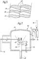
- the coating system 18 applied by the method of the present invention is shown more clearly in figures 4 and 5.
- the coating system 18 comprises a bond coating 22, deposited onto the metallic substrate 20 and a ceramic thermal barrier coating 24 deposited onto the bond coating 22.
- the bond coating 22 is generally a MCrAlY coating which has been deposited by thermal spraying or by physical vapour deposition (PVD).
- the bond coating 22 may be an aluminide coating which has been deposited by pack aluminising or may be a platinum-aluminide coating which has been deposited by platinum aluminising.
- the ceramic thermal barrier coating 24 is generally zirconia, yttria or a mixture thereof which has been deposited onto the bond coating 22 by physical vapour deposition (PVD). Alternatively the ceramic thermal barrier coating 24 may comprise any other suitable ceramic.
- the ceramic thermal barrier coating 24 has a columnar grained microstructure 28 which has good strain tolerance, good surface finish and good erosion resistance.
- the ceramic thermal barrier coating 24 has a relatively low thermal conductivity when compared to the ceramic thermal barrier coating 44 of the coating system 38 in figure 2 and is substantially the same or better than the thermal conductivity of the ceramic thermal barrier coating 54 of the coating system 48 in figure 2.
- the ceramic thermal barrier coating 24 in figures 4 and 5 has reduced thickness compared to the ceramic thermal barrier coating 44 in figure 2 for operation at the same temperature. Alternatively the same thickness of ceramic thermal barrier coating 24 may be used to allow operation at higher temperatures.
- the ceramic thermal barrier coating 24 has alternate layers 25 and 27 which have different structure to create interfaces 26 substantially parallel to the metallic substrate 20/bond coating 22 interface. These interfaces 26 provide paths of increased resistance to heat transfer to emulate the good thermal conductivity properties of thermal sprayed ceramic thermal barrier coatings.
- the structure in the alternate layers 25,27 of the ceramic thermal barrier coating 24 is columnar 28 to ensure that the strain tolerance of the ceramic thermal barrier coating 24 is not impaired.
- the columnar grains 28 in the layers 25,27 extend substantially perpendicular to the metallic substrate 20/bond coating 22 interface.
- the difference in structure in layers 25, 27 are the result of variations in the micro-structure and/or density/coarseness of the columnar grains 28 of the ceramic.
- columnar grains 28 in one of the layers 27 continue to grow into the adjacent layer 25 and that there is no interruption of the columnar grains 28 at the interfaces 26 between the layers 25,27. It may also be considered that the columnar grains 28 in the ceramic thermal barrier coating 24 extend through the full thickness of the coating 24, and that each columnar grain 28 has its structure modulated along its length by the provision of the layers 25,27.
- the coating system 18 according to the present invention is applied to the metallic substrate 20 by firstly depositing a MCrAlY bond coating 22 onto the metallic substrate 20 by plasma spraying.
- the MCrAlY may be deposited by physical vapour deposition (PVD).
- PVD physical vapour deposition
- a ceramic thermal barrier coating 24 is then deposited onto the MCrAlY bond coating 22.
- the apparatus 60 comprises a vacuum chamber 62 which has one or more pumps 64 to evacuate the vacuum chamber 62.
- An electron beam from an electron beam gun 66 is arranged to impinge upon a supply of ceramic vapour 68, i.e zirconia-yttria alloy, such that the ceramic is evaporated when the vacuum chamber 62 is evacuated.
- the metallic substrate 20 is also connected into an electrical circuit such that it may given a D.C. or R.F. potential 70.
- the apparatus 60 also includes supplies of argon 74, hydrogen 76 and oxygen 78 which are interconnected to the interior of the vacuum chamber 62 via a pipe 72. Each of the supplies of argon 74, hydrogen 76 and oxygen 78 are provided with valves to control the flow of the gases.
- the metallic substrate 20 with the deposited bond coating 22 is placed into the vacuum chamber 62.
- the vacuum chamber 62 is evacuated and the electron beam gun 66 directs electrons at the supply of ceramic vapour 68 to evaporate ceramic.
- the interior of the vacuum chamber 62 is supplied with controlled amounts of an inert gas and oxygen during the evaporation of the supply of ceramic vapour 68.
- the supply of inert gas, e.g. argon is to maintain the correct glow discharge, or plasma, conditions and the supply of oxygen is to maintain the composition of the ceramic thermal barrier coating at the stoichiometric ratio.
- the ceramic vapour deposits onto the MCrAlY bond coating 22.
- the ceramic vapour is deposited alternately, for predetermined periods of time, by the physical vapour deposition process (PVD) and by a plasma assisted physical vapour deposition process (PAPVD).
- PVD physical vapour deposition process
- PAPVD plasma assisted physical vapour deposition process
- a D.C. or R.F. potential is applied to the metallic substrate 20, this is known as ion plating.
- the first layer 25 of ceramic deposited onto the bond coating 22 is preferably deposited by plasma assisted physical vapour deposition (PAPVD) such that the ceramic at the interface with the bond coating 22 has a relatively high density and preferably has maximum density.
- PAPVD plasma assisted physical vapour deposition
- the use of the plasma assisted physical vapour deposition process is used to control the structure of the ceramic thermal barrier coating 24 all the way through its thickness, by controlling the way that the columnar ceramic grains 28 grow, to tailor the characteristics of the ceramic at particular positions.
- the plasma assisted physical vapour deposition process causes the columnar ceramic grains 28 to be packed together more closely.
- the D.C. or R.F. potential used during the plasma assisted physical vapour deposition process may be adjusted for deposition of different ceramic layers to control the density of the columnar ceramic grains 28.
- the interfaces 26 between the adjacent layers 25,27 should be as abrupt as is practical.
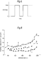
- the abrupt interfaces 26 are preferably achieved by the use of a simple switching action between the physical vapour deposition process and the plasma assisted physical vapour deposition process such that the voltage at the substrate follows a square wave form with time as shown in figure 6.
- the peak voltages in figure 6 correspond to the time when the layers 25 of ceramic are deposited by plasma assisted physical vapour deposition and the minimum voltages in figure 6 correspond to the time when the layers 27 of ceramic are deposited by physical vapour deposition.
- the switching points in figure 6 correspond to the time when the interfaces 26 between the layers 25 and 27 are produced.
- the first coating system comprised a plasma sprayed MCrAlY bond coating applied onto a nickel superalloy, N75 a nickel-chromium superalloy, and a purely physical vapour deposited (PVD) ceramic thermal barrier coating applied onto the bond coating.
- the vacuum chamber was evacuated to a pressure of 5 mTorr and the electron beam gun power was 8KV at 500mA.
- a total coating thickness of 90 x 10 ⁇ 6m was deposited.
- the thermal conductivity of the ceramic thermal barrier coating was measured at a temperature of 1000 o C and was 1.0 W/m/K.
- the second coating system comprised a plasma sprayed MCrAlY bond coating applied onto the same nickel superalloy and a purely plasma assisted physical vapour deposited (PAPVD) ceramic thermal barrier coating applied onto the bond coating.
- the vacuum chamber was evacuated to a pressure of 7 mTorr and the electron beam gun power was 8KV at 500mA.
- the R.F. power used during the PAPVD process was 500W.
- a total ceramic coating thickness of 160 x 10 ⁇ 6m was deposited.
- the thermal conductivity of the ceramic thermal barrier coating was measured at a temperature of 1000 o C and was 0.55 W/m/K.
- the third coating system comprised a plasma sprayed MCrAlY bond coating applied onto the same nickel superalloy and alternate layers of physical vapour deposited (PVD) and plasma assisted physical vapour deposited (PAPVD) ceramic thermal barrier coating applied onto the bond coating.
- the vacuum chamber was evacuated to a pressure of 4 mTorr and the electron beam gun power was 8KV at 500mA.
- the R.F. power used during the PAPVD process was 500W. A total of 70 layers of ceramic were deposited.
- Each of the 35 layers of ceramic deposited by the physical vapour deposition process (PVD) were 2 x 10 ⁇ 6m thick and each of the 35 layers of ceramic deposited by the plasma assisted physical vapour deposition process (PAPVD) were also 2 x 10 ⁇ 6m thick.
- the thermal conductivity of the ceramic thermal barrier coating was measured at a temperature of 1000 o C and was 0.3 W/m/K.
- the fourth coating system comprised a plasma sprayed MCrAlY bond coating applied onto the same nickel superalloy and alternate layers of physical vapour deposited (PVD) and plasma assisted physical vapour deposited (PAPVD) ceramic thermal barrier coating applied onto the bond coating.
- the vacuum chamber was evacuated to a pressure of 4 mTorr and the electron beam gun power was 8KV at 500mA.
- the R.F. power used during the PAPVD process was 500 W.
- Each of the 35 layers of ceramic deposited by the physical vapour deposition process (PVD) were 2 x 10 ⁇ 6m thick and each of the 35 layers of ceramic deposited by the plasma assisted physical vapour deposition process (PAPVD) were 1 x 10 ⁇ 6m thick.
- the thermal conductivity of the ceramic thermal barrier coating was measured at a temperature of 1000 o C and was 1.0 W/m/K.
- Figure 8 shows a graph of thermal conductivity against temperature for each of the four different coating systems.
- Line A indicates the thermal conductivity of the first coating system with temperature.
- Line B indicates the thermal conductivity of the second coating system with temperature.
- Line C indicates the thermal conductivity of the third coating system with temperature and finally line D indicates the thermal conductivity of the fourth coating system with temperature.
- the thermal conductivity of the third coating system is a third of that of the first coating system.
- the first coating system is the ceramic thermal barrier coating applied by the prior art method of physical vapour deposition (PVD).
- the thermal conductivity of the third coating system is also less than that of the second coating system.
- the second coating system is the ceramic thermal barrier coating applied purely by plasma assisted physical vapour deposition (PAPVD).
- the thermal conductivity of the fourth coating system is approximately the same as the first coating system.
- a further coating system 88 applied by the method of the present invention is shown more clearly in figures 9 and 10.
- the coating system 88 comprises a bond coating 92, deposited onto the metallic substrate 90, an interface layer 94 on the bond coating 92 and a ceramic thermal barrier coating 96 deposited onto the interface layer 94.
- the bond coating 92 is generally a MCrAlY coating which has been deposited by thermal spraying or by physical vapour deposition (PVD).
- the bond coating 92 may be an aluminide coating which has been deposited by pack aluminising or may be a platinum-aluminide coating which has been deposited by platinum aluminising.
- the bond coating 92 may be a MCrAlY coating with an aluminide top coating or a MCrAlY coating with a platinum aluminide top coating.
- the interface layer 94 comprises oxides or oxide/metal on the bond coating which improves the adhesion of the ceramic thermal barrier coating 96.
- the oxide is predominantly alumina which has controlled structure and properties.
- the metal comprises the metallic elements in the bond coating.
- the ceramic thermal barrier coating 96 is generally zirconia, yttria or a mixture thereof which has been deposited onto the interface layer 94 by physical vapour deposition (PVD). Alternatively the ceramic thermal barrier coating 96 may comprise any other suitable ceramic.
- the ceramic thermal barrier coating 96 has a columnar grained microstructure 100 which has good strain tolerance, good surface finish and good erosion resistance.
- the ceramic thermal barrier coating 96 has a relatively low thermal conductivity when compared to the ceramic thermal barrier coating 44 of the coating system 38 in figure 2 and is substantially the same or better than the thermal conductivity of the ceramic thermal barrier coating 54 of the coating system 48 in figure 3.
- the ceramic thermal barrier coating 96 in figures 9 and 10 has reduced thickness compared to the ceramic thermal barrier coating 44 in figure 2 for operation at the same temperature. Alternatively the same thickness of ceramic thermal barrier coating 96 may be used to allow operation at higher temperatures.
- the ceramic thermal barrier coating 96 has alternate layers 97 and 98 which have different structure to create interfaces 99 substantially parallel to the metallic substrate 90/bond coating 92 interface. These interfaces 99 provide paths of increased resistance to heat transfer to emulate the good thermal conductivity properties of thermal sprayed ceramic thermal barrier coatings.
- the structure in the alternate layers 97,98 of the ceramic thermal barrier coating 96 is columnar 100 to ensure that the strain tolerance of the ceramic thermal barrier coating 96 is not impaired.
- the columnar grains 100 in the layers 97,98 extend substantially perpendicular to the metallic substrate 90/bond coating 92 interface.
- the difference in structure in layers 97, 98 are the result of variations in the structure and/or density/coarseness of the columnar grains 100 of the ceramic.
- the columnar grains 100 in one of the layers 98 continue to grow into the adjacent layer 97 and there are no interruptions of the columnar grains 100 at the interfaces 99 between the layers 97,98.
- the columnar grains 100 in the ceramic thermal barrier coating 96 extend through the full thickness of the coating 96 and each columnar grain 100 has its structure modulated along its length by the provision of the layers 97,98.
- the coating system 88 is applied to the metallic substrate 90 by firstly depositing a MCrAlY bond coating 92 onto the metallic substrate 90 by plasma spraying.
- the MCrAlY may be deposited by physical vapour deposition (PVD).
- PVD physical vapour deposition
- the surface of the bond coating 92 is then modified to create an oxide or oxide/metal interface layer 94 which has controlled structure and properties to improve the adhesion of the subsequently deposited ceramic thermal barrier coating 96.
- a ceramic thermal barrier coating 96 is then deposited onto the interface layer 94.
- the metallic substrate 90 with the deposited bond coating 92 is placed into the vacuum chamber 62.
- the vacuum chamber 62 is evacuated and an electrical bias, e.g. a D.C. potential or R.F. field, is applied to the metallic substrate 90 prior to the deposition of the columnar grained ceramic thermal barrier coating 96 in order to modify the structure and/or chemistry of the surface of the bond coating 92.
- Controlled amounts of gases are introduced into the interior of the vacuum chamber 62 during this phase of the process, for example argon-oxygen, argon-hydrogen or argon.
- the electrical bias produces chemically active glow discharges or plasmas in the case of argon-oxygen and argon-hydrogen, or produces neutral glow discharges or plasmas in the case of argon.
- the argon plasma may be used to produce argon ions which bombard the surface of the bond coating 92 to clean the surface i.e. to remove undesired oxides and/or any contaminants.
- the argon-hydrogen plasma may be used to provide enhanced cleaning of the surface of the bond coating 92 because the additional hydrogen ions chemically react with the undesired contaminants.
- the argon-oxygen plasma, or argon-hydrogen plasma provides controlled production of desired bonding oxides in an interface 94 on the surface of the bond coating 92.
- the interface 94 improves the adhesion of the subsequently deposited ceramic thermal barrier coating 96.
- the gases used during the modification of the surface of the bond coating 92 to produce the interface layer 94 are then extracted from the vacuum chamber 62.
- the electron beam gun 66 directs electrons at the supply of ceramic vapour 68 to evaporate ceramic.
- the interior of the vacuum chamber 62 is supplied with controlled amounts of an inert gas and oxygen during the evaporation of the supply of ceramic vapour 68.
- the supply of inert gas, e.g. argon, is to maintain the correct glow discharge, or plasma, conditions and the supply of oxygen is to maintain the composition of the ceramic thermal barrier coating at the stoichiometric ratio.
- the ceramic vapour deposits onto the interface layer 94.
- the ceramic vapour is deposited alternately, for predetermined periods of time, by the physical vapour deposition process (PVD) and by a plasma assisted physical vapour deposition process (PAPVD).
- PVD physical vapour deposition process
- PAPVD plasma assisted physical vapour deposition process
- a D.C. or R.F. potential is applied to the metallic substrate 90.
- the first layer 97 of ceramic deposited onto the interface layer 94 is preferably deposited by plasma assisted physical vapour deposition (PAPVD) such that the ceramic at the interface with the interface layer 94 has a relatively high density and preferably has maximum density.
- PAPVD plasma assisted physical vapour deposition
- the use of the plasma assisted physical vapour deposition process is used to control the structure of the ceramic thermal barrier coating 96 all the way through its thickness, by controlling the way that the columnar ceramic grains 100 grow, to tailor the characteristics of the ceramic at particular positions.
- the plasma assisted physical vapour deposition process causes the columnar ceramic grains 100 to be packed together more closely.
- the D.C. or R.F. potential used during the plasma assisted physical vapour deposition process may be adjusted for deposition of different ceramic layers to control the density of the columnar ceramic grains 100.
- an initial large voltage is applied to the metallic substrate 90 to modify the structure and/or chemistry of the surface of the bond coating 92.
- the magnitude of the initial large voltage is determined by the need to remove contaminants or undesirable oxides from the bond coating 92 prior to establishing the desired oxide structure-composition to achieve satisfactory adhesion of the thermal barrier coating 96.
- the desired oxide may be grown thermally or in the presence of a glow discharge.
- the interfaces 99 between the adjacent layers 97,98 are kept as abrupt as is practical.
- the abrupt interfaces 99 are preferably achieved by the use of a simple switching action as shown in region B of figure 11 between the physical vapour deposition process such that the voltage at the substrate follows a square wave form with time.
- the peak voltage in region B of figure 11 correspond to the time when the layers 97 of ceramic are deposited by PAPVD and the minimum voltages in region B of figure 11 correspond to the time when the layers 98 of ceramic are deposited by PVD.
- the switching points correspond to the time when the interfaces 99 are produced.
- the current drawn in the circuit as a function of substrate voltage is shown in figure 12, more current is drawn as the voltage increases.
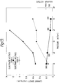
- the minimum voltages are of the order of three hundred volts as shown in figure 13, and the current densities are typically greater than 0.1 mA/sq cm. This increases at any given pressure with applied substrate voltage.
- the structurally modulated thermal barrier coating was produced by switching between a DC applied substrate bias, having a peak voltage of 2000 volts (negative), and ground. The time interval was 1 minute at each of the voltage levels and the pressure was 10 mtorr.
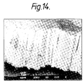
- Figure 14 is a scanning electron micrograph of a fracture cross-section through the thermal barrier coating. The continuous columnar grains can be seen extending through the full thickness of the thermal barrier coating and the modulated structure of the columns is evident. The outer portion of the coating was deposited purely in the PVD mode.
- the voltage applied to the substrate during the plasma assisted physical vapour depositions part of the process is sufficient to cause densification of the thermal barrier coating but is not sufficient to cause renucleation/grain growth within the structure with subsequent loss of the major, through thickness, columnar boundaries.
- the physical vapour deposition process described uses electron beam evaporation, however, other physical vapour deposition processes may be used for example sputtering or arc evaporation.
- thermal barrier coatings described in the examples are ceramic materials, however the thermal barrier coating may be any suitable material of low thermal conductivity.
- Materials suitable for use as thermal barrier coatings are generally oxides, for example zirconia, yttria, hafnia, ceria or combinations of any two or more thereof.
- the different layers in the thermal barrier coating are intended to have substantially the same composition, however the process of applying the thermal barrier coating may result in some compositional differences between the different layers.
Landscapes
- Chemical & Material Sciences (AREA)
- Engineering & Computer Science (AREA)
- Mechanical Engineering (AREA)
- Materials Engineering (AREA)
- Organic Chemistry (AREA)
- Metallurgy (AREA)
- Chemical Kinetics & Catalysis (AREA)
- Inorganic Chemistry (AREA)
- Ceramic Engineering (AREA)
- General Engineering & Computer Science (AREA)
- Physical Vapour Deposition (AREA)
- Other Surface Treatments For Metallic Materials (AREA)
- Coating By Spraying Or Casting (AREA)
- Turbine Rotor Nozzle Sealing (AREA)
Abstract
Description
- The present invention is concerned with coatings for metallic substrates, and is particularly concerned with ceramic thermal barrier coatings for metallic components for use in gas turbine engines.
- It is known in the prior art to apply ceramic to a metallic substrate to produce a ceramic thermal barrier coating by the thermal, or plasma, spray process. In this technique the ceramic is applied onto a bond coat, for example a MCrAlY bond coat, which has been applied to the metallic substrate.
- It is also known in the prior art to apply ceramic to a metallic substrate to produce a ceramic thermal barrier coating by the physical vapour deposition (PVD) process. In this technique the ceramic is applied onto a bond coat, for example a MCrAlY coating with an alumina interface layer, which has been applied to the metallic substrate. The ceramic thermal barrier coatings deposited by the PVD process have benefits over the ceramic thermal barrier coatings deposited by a thermal spray process. The main benefit is improved thermal shock resistance due to the columnar structure of the ceramic thermal barrier coating produced by the PVD process. Other benefits are improved erosion resistance and improved aerothermal performance.
- The present invention seeks to provide an article which comprises a metallic substrate having a bond coating and thermal barrier coating in which the bond coating provides a better bond between the thermal barrier coating and the metallic substrate.
- Accordingly the present invention provides an article comprising a metallic substrate, a bond coating on the metallic substrate, the bond coating comprising a MCrAlY coating on the metallic substrate, an aluminide coating on the MCrAlY coating, an interface layer on the aluminide coating, the interface layer comprising alumina, and a thermal barrier coating on the interface layer.
- The use of a MCrAlY coating provided with an aluminide coating provides more aluminium content to bond the thermal barrier coating onto the substrate.
- The aluminide coating may be a platinum aluminide coating.
- The present invention also provides an article comprising a metallic substrate, a bond coating on the metallic substrate, the bond coating comprising an aluminide coating on the metallic substrate, a platinum aluminide coating on the aluminide coating, an interface layer on the platinum aluminide coating, the interface layer comprising alumina, and a thermal barrier coating on the interface layer.
- The thermal barrier coating may have columnar grains.
- The columnar grains may have layers with different structures.
- The thermal barrier coating may comprise zirconia, yttria or a mixture thereof.
- The metallic substrate may be a superalloy substrate.
- The present invention also provides a method of manufacturing an article comprising applying a MCrAlY coating to a metallic substrate, forming an aluminide coating on the MCrAlY coating, forming an alumina interface layer on the aluminide coating and depositing a thermal barrier coating on the alumina interface layer.
- The thermal barrier coating may be deposited by vapour deposition.
- The thermal barrier coating may be deposited by vapour deposition and plasma assisted vapour deposition.
- The MCrAlY may be deposited by vapour depositions.
- The present invention also provides a method of manufacturing an article comprising applying a MCrAlY or an aluminide coating to a metallic substrate, forming a platinum aluminide coating on the MCrAlY or aluminide coating, forming an alumina interface layer on the platinum aluminide coating and depositing a thermal barrier coating on the alumina interface layer.
- The aluminide coating may be formed by pack aluminising.
- The platinum aluminide coating may be formed by platinum aluminising.
- The alumina may be formed by oxidation.
- The present invention will be more fully described by way of example, with reference to the accompanying drawings in which:-
- Figure 1 is a perspective view of a gas turbine engine turbine blade according to the present invention.
- Figure 2 is a sectional view through an article having a thermal barrier coating applied by a first prior art method.
- Figure 3 is a sectional view through an article having a thermal barrier coating applied by a second prior art method.
- Figure 4 is a sectional view through an article having a thermal barrier coating applied according to the present invention.
- Figure 5 is an enlarged view of a portion of the thermal barrier coating shown in figure 4.
- Figure 6 is a graph of voltage applied to the substrate against time during the application of the thermal barrier coating.
- Figure 7 is a sectional view through an apparatus for use in the method of applying the thermal barrier coating according to the present invention.
- Figure 8 is a graph of thermal conductivity against temperature for several thermal barrier coatings.
- Figure 9 is a sectional view through an article having an alternative thermal barrier coating applied according to the present invention.
- Figure 10 is an enlarged view of a portion of the thermal barrier coating in Figure 9.
- Figure 11 is a graph of voltage applied to the substrate against time during the application of the thermal barrier coating.
- Figure 12 is a graph of current density against substrate voltage.
- Figure 13 is a graph of current density against pressure.
- Figure 14 is a micrograph of a fracture cross-section through an article according to the present invention.
- A gas turbine
engine turbine blade 10 is shown in figure 1. Theturbine blade 10 comprises ashaped root portion 12, for attaching theturbine blade 10 to a turbine rotor, aplatform portion 14, for defining a portion of the radially inner boundary of the gas flow path through the turbine, and anaerofoil portion 16, which extracts energy from the hot gases passing through the turbine. Theplatform portion 14, and theaerofoil portion 16, of theturbine blade 10 are provided with acoating system 18 which allows theturbine blade 10 to operate at higher gas temperatures. - The
coating system 18 comprises abond coating 22, deposited onto themetallic substrate 20 of theturbine blade 10, and a ceramicthermal barrier coating 24 deposited onto thebond coating 22. - A
coating system 38 applied by a first prior art method is shown in figure 2. Thecoating system 38 comprises abond coating 42, deposited onto themetallic substrate 40 and a ceramicthermal barrier coating 44 deposited onto thebond coating 42. Thebond coating 42 is generally a MCrAlY coating which has been deposited by thermal spraying or by physical vapour deposition (PVD), or the bond coating may be an aluminide coating. Thebond coating 42 may additionally have an alumina layer. The ceramicthermal barrier coating 44 is generally zirconia or yttria or a mixture thereof which has been deposited onto thebond coating 42 by physical vapour deposition (PVD). The ceramicthermal barrier coating 44 has a columnargrained microstructure 46 which has a relatively high thermal conductivity, good strain tolerance, good surface finish and good erosion resistance. - A
coating system 48 applied by a second prior art method is shown in figure 3. Thecoating system 48 comprises abond coating 52, deposited onto themetallic substrate 50 and a ceramicthermal barrier coating 54 deposited onto thebond coating 52. Thebond coating 52 is generally a MCrAlY coating which has been deposited by thermal spraying or by physical vapour deposition (PVD), or the bond coating may be an aluminide coating. The ceramicthermal barrier coating 54 is generally zirconia or yttria or a mixture thereof which has been deposited onto thebond coating 52 by thermal spraying. The ceramicthermal barrier coating 54 has a "brick wall" microstructure which has poor erosion resistance but has a relatively low thermal conductivity when compared to the thermal conductivity of the ceramic thermal barrier coating applied by the first prior art method mentioned above. - The
coating system 18 applied by the method of the present invention is shown more clearly in figures 4 and 5. Thecoating system 18 comprises abond coating 22, deposited onto themetallic substrate 20 and a ceramicthermal barrier coating 24 deposited onto thebond coating 22. - The
bond coating 22 is generally a MCrAlY coating which has been deposited by thermal spraying or by physical vapour deposition (PVD). Alternatively thebond coating 22 may be an aluminide coating which has been deposited by pack aluminising or may be a platinum-aluminide coating which has been deposited by platinum aluminising. - The ceramic
thermal barrier coating 24 is generally zirconia, yttria or a mixture thereof which has been deposited onto thebond coating 22 by physical vapour deposition (PVD). Alternatively the ceramicthermal barrier coating 24 may comprise any other suitable ceramic. The ceramicthermal barrier coating 24 has a columnargrained microstructure 28 which has good strain tolerance, good surface finish and good erosion resistance. The ceramicthermal barrier coating 24 has a relatively low thermal conductivity when compared to the ceramicthermal barrier coating 44 of thecoating system 38 in figure 2 and is substantially the same or better than the thermal conductivity of the ceramicthermal barrier coating 54 of thecoating system 48 in figure 2. The ceramic thermal barrier coating 24 in figures 4 and 5 has reduced thickness compared to the ceramic thermal barrier coating 44 in figure 2 for operation at the same temperature. Alternatively the same thickness of ceramicthermal barrier coating 24 may be used to allow operation at higher temperatures. - The ceramic
thermal barrier coating 24 hasalternate layers interfaces 26 substantially parallel to themetallic substrate 20/bond coating 22 interface. Theseinterfaces 26 provide paths of increased resistance to heat transfer to emulate the good thermal conductivity properties of thermal sprayed ceramic thermal barrier coatings. The structure in thealternate layers thermal barrier coating 24 is columnar 28 to ensure that the strain tolerance of the ceramicthermal barrier coating 24 is not impaired. Thecolumnar grains 28 in thelayers metallic substrate 20/bond coating 22 interface. The difference in structure inlayers columnar grains 28 of the ceramic. - It is to be noted that the
columnar grains 28 in one of thelayers 27 continue to grow into theadjacent layer 25 and that there is no interruption of thecolumnar grains 28 at theinterfaces 26 between thelayers columnar grains 28 in the ceramicthermal barrier coating 24 extend through the full thickness of thecoating 24, and that eachcolumnar grain 28 has its structure modulated along its length by the provision of thelayers - The
coating system 18 according to the present invention is applied to themetallic substrate 20 by firstly depositing aMCrAlY bond coating 22 onto themetallic substrate 20 by plasma spraying. Alternatively the MCrAlY may be deposited by physical vapour deposition (PVD). A ceramicthermal barrier coating 24 is then deposited onto theMCrAlY bond coating 22. - An apparatus used for depositing the ceramic
thermal barrier coating 24 onto theMCrAlY bond coating 22 is shown in figure 7. Theapparatus 60 comprises avacuum chamber 62 which has one ormore pumps 64 to evacuate thevacuum chamber 62. An electron beam from anelectron beam gun 66 is arranged to impinge upon a supply ofceramic vapour 68, i.e zirconia-yttria alloy, such that the ceramic is evaporated when thevacuum chamber 62 is evacuated. Themetallic substrate 20 is also connected into an electrical circuit such that it may given a D.C. or R.F. potential 70. Theapparatus 60 also includes supplies ofargon 74,hydrogen 76 andoxygen 78 which are interconnected to the interior of thevacuum chamber 62 via apipe 72. Each of the supplies ofargon 74,hydrogen 76 andoxygen 78 are provided with valves to control the flow of the gases. - In order to deposit the ceramic
thermal barrier coating 24 onto theMCrAlY bond coating 22 themetallic substrate 20 with the depositedbond coating 22 is placed into thevacuum chamber 62. Thevacuum chamber 62 is evacuated and theelectron beam gun 66 directs electrons at the supply ofceramic vapour 68 to evaporate ceramic. The interior of thevacuum chamber 62 is supplied with controlled amounts of an inert gas and oxygen during the evaporation of the supply ofceramic vapour 68. The supply of inert gas, e.g. argon, is to maintain the correct glow discharge, or plasma, conditions and the supply of oxygen is to maintain the composition of the ceramic thermal barrier coating at the stoichiometric ratio. The ceramic vapour deposits onto theMCrAlY bond coating 22. In order to produce thelayers thermal barrier coating 24, the ceramic vapour is deposited alternately, for predetermined periods of time, by the physical vapour deposition process (PVD) and by a plasma assisted physical vapour deposition process (PAPVD). In the plasma assisted physical vapour deposition process (PAPVD) a D.C. or R.F. potential is applied to themetallic substrate 20, this is known as ion plating. - The
first layer 25 of ceramic deposited onto thebond coating 22 is preferably deposited by plasma assisted physical vapour deposition (PAPVD) such that the ceramic at the interface with thebond coating 22 has a relatively high density and preferably has maximum density. - The use of the plasma assisted physical vapour deposition process (PAPVD) is used to control the structure of the ceramic
thermal barrier coating 24 all the way through its thickness, by controlling the way that the columnarceramic grains 28 grow, to tailor the characteristics of the ceramic at particular positions. The plasma assisted physical vapour deposition process (PAPVD) causes the columnarceramic grains 28 to be packed together more closely. The D.C. or R.F. potential used during the plasma assisted physical vapour deposition process (PAPVD) may be adjusted for deposition of different ceramic layers to control the density of the columnarceramic grains 28. - In order to achieve the maximum difference in thermal conductivity between
adjacent layers interfaces 26 between theadjacent layers abrupt interfaces 26 are preferably achieved by the use of a simple switching action between the physical vapour deposition process and the plasma assisted physical vapour deposition process such that the voltage at the substrate follows a square wave form with time as shown in figure 6. The peak voltages in figure 6 correspond to the time when thelayers 25 of ceramic are deposited by plasma assisted physical vapour deposition and the minimum voltages in figure 6 correspond to the time when thelayers 27 of ceramic are deposited by physical vapour deposition. The switching points in figure 6 correspond to the time when theinterfaces 26 between thelayers - In an experiment four different coating systems were applied to a metallic substrate. The first coating system comprised a plasma sprayed MCrAlY bond coating applied onto a nickel superalloy, N75 a nickel-chromium superalloy, and a purely physical vapour deposited (PVD) ceramic thermal barrier coating applied onto the bond coating. The vacuum chamber was evacuated to a pressure of 5 mTorr and the electron beam gun power was 8KV at 500mA. A total coating thickness of 90 x 10⁻⁶m was deposited. The thermal conductivity of the ceramic thermal barrier coating was measured at a temperature of 1000oC and was 1.0 W/m/K.
- The second coating system comprised a plasma sprayed MCrAlY bond coating applied onto the same nickel superalloy and a purely plasma assisted physical vapour deposited (PAPVD) ceramic thermal barrier coating applied onto the bond coating. The vacuum chamber was evacuated to a pressure of 7 mTorr and the electron beam gun power was 8KV at 500mA. The R.F. power used during the PAPVD process was 500W. A total ceramic coating thickness of 160 x 10⁻⁶m was deposited. The thermal conductivity of the ceramic thermal barrier coating was measured at a temperature of 1000oC and was 0.55 W/m/K.
- The third coating system comprised a plasma sprayed MCrAlY bond coating applied onto the same nickel superalloy and alternate layers of physical vapour deposited (PVD) and plasma assisted physical vapour deposited (PAPVD) ceramic thermal barrier coating applied onto the bond coating. The vacuum chamber was evacuated to a pressure of 4 mTorr and the electron beam gun power was 8KV at 500mA. The R.F. power used during the PAPVD process was 500W. A total of 70 layers of ceramic were deposited. Each of the 35 layers of ceramic deposited by the physical vapour deposition process (PVD) were 2 x 10⁻⁶m thick and each of the 35 layers of ceramic deposited by the plasma assisted physical vapour deposition process (PAPVD) were also 2 x 10⁻⁶m thick. The thermal conductivity of the ceramic thermal barrier coating was measured at a temperature of 1000oC and was 0.3 W/m/K.
- The fourth coating system comprised a plasma sprayed MCrAlY bond coating applied onto the same nickel superalloy and alternate layers of physical vapour deposited (PVD) and plasma assisted physical vapour deposited (PAPVD) ceramic thermal barrier coating applied onto the bond coating. The vacuum chamber was evacuated to a pressure of 4 mTorr and the electron beam gun power was 8KV at 500mA. The R.F. power used during the PAPVD process was 500 W. A total of 70 layers of ceramic were deposited. Each of the 35 layers of ceramic deposited by the physical vapour deposition process (PVD) were 2 x 10⁻⁶m thick and each of the 35 layers of ceramic deposited by the plasma assisted physical vapour deposition process (PAPVD) were 1 x 10⁻⁶m thick. The thermal conductivity of the ceramic thermal barrier coating was measured at a temperature of 1000oC and was 1.0 W/m/K.
- Figure 8 shows a graph of thermal conductivity against temperature for each of the four different coating systems. Line A indicates the thermal conductivity of the first coating system with temperature. Line B indicates the thermal conductivity of the second coating system with temperature. Line C indicates the thermal conductivity of the third coating system with temperature and finally line D indicates the thermal conductivity of the fourth coating system with temperature.
- The thermal conductivity of the third coating system is a third of that of the first coating system. The first coating system is the ceramic thermal barrier coating applied by the prior art method of physical vapour deposition (PVD). The thermal conductivity of the third coating system is also less than that of the second coating system. The second coating system is the ceramic thermal barrier coating applied purely by plasma assisted physical vapour deposition (PAPVD).
- The thermal conductivity of the fourth coating system is approximately the same as the first coating system.
- A
further coating system 88 applied by the method of the present invention is shown more clearly in figures 9 and 10. Thecoating system 88 comprises abond coating 92, deposited onto themetallic substrate 90, aninterface layer 94 on thebond coating 92 and a ceramicthermal barrier coating 96 deposited onto theinterface layer 94. - The
bond coating 92 is generally a MCrAlY coating which has been deposited by thermal spraying or by physical vapour deposition (PVD). Alternatively thebond coating 92 may be an aluminide coating which has been deposited by pack aluminising or may be a platinum-aluminide coating which has been deposited by platinum aluminising. Thebond coating 92 may be a MCrAlY coating with an aluminide top coating or a MCrAlY coating with a platinum aluminide top coating. - The
interface layer 94 comprises oxides or oxide/metal on the bond coating which improves the adhesion of the ceramicthermal barrier coating 96. The oxide is predominantly alumina which has controlled structure and properties. The metal comprises the metallic elements in the bond coating. - The ceramic
thermal barrier coating 96 is generally zirconia, yttria or a mixture thereof which has been deposited onto theinterface layer 94 by physical vapour deposition (PVD). Alternatively the ceramicthermal barrier coating 96 may comprise any other suitable ceramic. The ceramicthermal barrier coating 96 has a columnargrained microstructure 100 which has good strain tolerance, good surface finish and good erosion resistance. The ceramicthermal barrier coating 96 has a relatively low thermal conductivity when compared to the ceramicthermal barrier coating 44 of thecoating system 38 in figure 2 and is substantially the same or better than the thermal conductivity of the ceramicthermal barrier coating 54 of thecoating system 48 in figure 3. The ceramicthermal barrier coating 96 in figures 9 and 10 has reduced thickness compared to the ceramicthermal barrier coating 44 in figure 2 for operation at the same temperature. Alternatively the same thickness of ceramicthermal barrier coating 96 may be used to allow operation at higher temperatures. - The ceramic
thermal barrier coating 96 hasalternate layers interfaces 99 substantially parallel to themetallic substrate 90/bond coating 92 interface. Theseinterfaces 99 provide paths of increased resistance to heat transfer to emulate the good thermal conductivity properties of thermal sprayed ceramic thermal barrier coatings. The structure in thealternate layers thermal barrier coating 96 is columnar 100 to ensure that the strain tolerance of the ceramicthermal barrier coating 96 is not impaired. Thecolumnar grains 100 in thelayers metallic substrate 90/bond coating 92 interface. The difference in structure inlayers columnar grains 100 of the ceramic. - The
columnar grains 100 in one of thelayers 98 continue to grow into theadjacent layer 97 and there are no interruptions of thecolumnar grains 100 at theinterfaces 99 between thelayers columnar grains 100 in the ceramicthermal barrier coating 96 extend through the full thickness of thecoating 96 and eachcolumnar grain 100 has its structure modulated along its length by the provision of thelayers - The
coating system 88 according to the present invention is applied to themetallic substrate 90 by firstly depositing aMCrAlY bond coating 92 onto themetallic substrate 90 by plasma spraying. Alternatively the MCrAlY may be deposited by physical vapour deposition (PVD). The surface of thebond coating 92 is then modified to create an oxide or oxide/metal interface layer 94 which has controlled structure and properties to improve the adhesion of the subsequently deposited ceramicthermal barrier coating 96. A ceramicthermal barrier coating 96 is then deposited onto theinterface layer 94. - In order to create the
interface layer 94 on the surface of thebond coating 92 and to deposit the ceramicthermal barrier coating 96 onto theinterface layer 94 themetallic substrate 90 with the depositedbond coating 92 is placed into thevacuum chamber 62. - The
vacuum chamber 62 is evacuated and an electrical bias, e.g. a D.C. potential or R.F. field, is applied to themetallic substrate 90 prior to the deposition of the columnar grained ceramicthermal barrier coating 96 in order to modify the structure and/or chemistry of the surface of thebond coating 92. Controlled amounts of gases are introduced into the interior of thevacuum chamber 62 during this phase of the process, for example argon-oxygen, argon-hydrogen or argon. The electrical bias produces chemically active glow discharges or plasmas in the case of argon-oxygen and argon-hydrogen, or produces neutral glow discharges or plasmas in the case of argon. The argon plasma may be used to produce argon ions which bombard the surface of thebond coating 92 to clean the surface i.e. to remove undesired oxides and/or any contaminants. The argon-hydrogen plasma may be used to provide enhanced cleaning of the surface of thebond coating 92 because the additional hydrogen ions chemically react with the undesired contaminants. When the surface of thebond coating 92 is cleaned of undesired oxides and/or contaminants the argon-oxygen plasma, or argon-hydrogen plasma, provides controlled production of desired bonding oxides in aninterface 94 on the surface of thebond coating 92. Theinterface 94 improves the adhesion of the subsequently deposited ceramicthermal barrier coating 96. The gases used during the modification of the surface of thebond coating 92 to produce theinterface layer 94 are then extracted from thevacuum chamber 62. - The
electron beam gun 66 directs electrons at the supply ofceramic vapour 68 to evaporate ceramic. The interior of thevacuum chamber 62 is supplied with controlled amounts of an inert gas and oxygen during the evaporation of the supply ofceramic vapour 68. The supply of inert gas, e.g. argon, is to maintain the correct glow discharge, or plasma, conditions and the supply of oxygen is to maintain the composition of the ceramic thermal barrier coating at the stoichiometric ratio. The ceramic vapour deposits onto theinterface layer 94. In order to produce thelayers thermal barrier coating 96, the ceramic vapour is deposited alternately, for predetermined periods of time, by the physical vapour deposition process (PVD) and by a plasma assisted physical vapour deposition process (PAPVD). In the plasma assisted physical vapour deposition process (PAPVD) a D.C. or R.F. potential is applied to themetallic substrate 90. - The
first layer 97 of ceramic deposited onto theinterface layer 94 is preferably deposited by plasma assisted physical vapour deposition (PAPVD) such that the ceramic at the interface with theinterface layer 94 has a relatively high density and preferably has maximum density. - The use of the plasma assisted physical vapour deposition process (PAPVD) is used to control the structure of the ceramic
thermal barrier coating 96 all the way through its thickness, by controlling the way that the columnarceramic grains 100 grow, to tailor the characteristics of the ceramic at particular positions. The plasma assisted physical vapour deposition process (PAPVD) causes the columnarceramic grains 100 to be packed together more closely. The D.C. or R.F. potential used during the plasma assisted physical vapour deposition process (PAPVD) may be adjusted for deposition of different ceramic layers to control the density of the columnarceramic grains 100. - In region A of figure 11 an initial large voltage is applied to the
metallic substrate 90 to modify the structure and/or chemistry of the surface of thebond coating 92. The magnitude of the initial large voltage is determined by the need to remove contaminants or undesirable oxides from thebond coating 92 prior to establishing the desired oxide structure-composition to achieve satisfactory adhesion of thethermal barrier coating 96. The desired oxide may be grown thermally or in the presence of a glow discharge. - In order to achieve the maximum difference in thermal conductivity between
adjacent layers interfaces 99 between theadjacent layers abrupt interfaces 99 are preferably achieved by the use of a simple switching action as shown in region B of figure 11 between the physical vapour deposition process such that the voltage at the substrate follows a square wave form with time. The peak voltage in region B of figure 11 correspond to the time when thelayers 97 of ceramic are deposited by PAPVD and the minimum voltages in region B of figure 11 correspond to the time when thelayers 98 of ceramic are deposited by PVD. The switching points correspond to the time when theinterfaces 99 are produced. - The current drawn in the circuit as a function of substrate voltage is shown in figure 12, more current is drawn as the voltage increases. In order to sustain a glow discharge for the plasma assisted physical vapour deposition process, in this configuration for electron beam evaporation, the minimum voltages are of the order of three hundred volts as shown in figure 13, and the current densities are typically greater than 0.1 mA/sq cm. This increases at any given pressure with applied substrate voltage.
- In another experiment the structurally modulated thermal barrier coating was produced by switching between a DC applied substrate bias, having a peak voltage of 2000 volts (negative), and ground. The time interval was 1 minute at each of the voltage levels and the pressure was 10 mtorr. Figure 14 is a scanning electron micrograph of a fracture cross-section through the thermal barrier coating. The continuous columnar grains can be seen extending through the full thickness of the thermal barrier coating and the modulated structure of the columns is evident. The outer portion of the coating was deposited purely in the PVD mode.
- The voltage applied to the substrate during the plasma assisted physical vapour depositions part of the process is sufficient to cause densification of the thermal barrier coating but is not sufficient to cause renucleation/grain growth within the structure with subsequent loss of the major, through thickness, columnar boundaries.
- The physical vapour deposition process described uses electron beam evaporation, however, other physical vapour deposition processes may be used for example sputtering or arc evaporation.
- Although the description has referred to physical vapour deposition to deposit the ceramic thermal barrier coating it may be equally possible to deposit the ceramic thermal barrier coating by chemical vapour deposition. The alternate layers may then be deposited using chemical vapour deposition and plasma assisted chemical vapour deposition.
- The thermal barrier coatings described in the examples are ceramic materials, however the thermal barrier coating may be any suitable material of low thermal conductivity. Materials suitable for use as thermal barrier coatings are generally oxides, for example zirconia, yttria, hafnia, ceria or combinations of any two or more thereof.
- The different layers in the thermal barrier coating are intended to have substantially the same composition, however the process of applying the thermal barrier coating may result in some compositional differences between the different layers.
- There appears to be an optimum spacing between the layers of ceramic for improved thermal conductivity when comparing the results of the third and fourth coating systems to the first coating system.
Claims (15)
- An article comprising a metallic substrate (90), a bond coating (92) on the metallic substrate (90), the bond coating (92) comprising a MCrAlY coating on the metallic substrate (90) and an interface layer (94), the interface layer (94) comprising alumina, a thermal barrier coating (96) on the interface layer (94), characterised in that the bond coating (92) includes an aluminide coating on the MCrAlY coating and the interface (94) is on the aluminide coating.
- An article as claimed in claim 1 characterised in that the aluminide coating is a platinum aluminide coating.
- An article comprising a metallic substrate (90), a bond coating (92) on the metallic substrate (90), the bond coating (92) comprising an aluminide coating on the metallic substrate (90) and an interface layer (94), the interface layer (94) comprising alumina, a thermal barrier coating (96) on the interface layer (94), characterised in that the bond coating (92) includes a platinum aluminide coating on the aluminide coating of the bond coating (92), and the interface layer (94) is on the platinum aluminide coating.
- An article as claimed in claim 1, claim 2 or claim 3 characterised in that the thermal barrier coating (96) has columnar grains (100).
- An article as claimed in claim 4 characterised in that columnar grains (100) have layers (97,98) with different structures.
- An article as claimed in any of claims 1 to 5 characterised in that the thermal barrier coating (96) comprises zirconia, yttria or a mixture thereof.
- An article as claimed in any of claims 1 to 6 characterised in that the metallic substrate (90) is a superalloy substrate.
- A method of manufacturing an article comprising applying a MCrAlY coating (92) to a metallic substrate (90), characterised by forming an aluminide coating on the MCrAlY coating (92), oxidising the aluminide coating to form an alumina interface layer (94) and depositing a thermal barrier coating (96) on the alumina interface layer (94).
- A method of manufacturing an article comprising applying a MCrAlY or an aluminide coating (92) to a metallic substrate (90), characterised by forming a platinum aluminide coating on the MCrAlY or aluminide coating (92), oxidising the platinum aluminide coating to form an alumina interface layer (94) and depositing a thermal barrier coating (96) on the alumina interface layer (94).
- An method as claimed in claim 8 or claim 9 characterised by depositing the thermal barrier coating (96) by vapour deposition.
- A method as claimed in claim 10 characterised by depositing the thermal barrier coating (96) by vapour deposition and plasma assisted vapour deposition.
- A method as claimed in any of claims 8 to 11 characterised by depositing the MCrAlY by vapour deposition.
- An method as claimed in claim 8 characterised by forming the aluminide coating by pack aluminising.
- A method as claimed in claim 9 characterised by forming the platinum aluminide coating by platinum aluminising.
- A method as claimed in any of claims 8 to 14 characterised by the metallic substrate being a superalloy substrate.
Applications Claiming Priority (3)
| Application Number | Priority Date | Filing Date | Title |
|---|---|---|---|
| GB929204791A GB9204791D0 (en) | 1992-03-05 | 1992-03-05 | A coated article |
| GB9204791 | 1992-03-05 | ||
| EP93905499A EP0628090B1 (en) | 1992-03-05 | 1993-03-03 | A coated article |
Related Parent Applications (2)
| Application Number | Title | Priority Date | Filing Date |
|---|---|---|---|
| EP93905499.5 Division | 1993-03-03 | ||
| EP93905499A Division EP0628090B1 (en) | 1992-03-05 | 1993-03-03 | A coated article |
Publications (3)
| Publication Number | Publication Date |
|---|---|
| EP0705912A2 true EP0705912A2 (en) | 1996-04-10 |
| EP0705912A3 EP0705912A3 (en) | 1996-10-16 |
| EP0705912B1 EP0705912B1 (en) | 1998-05-27 |
Family
ID=10711558
Family Applications (2)
| Application Number | Title | Priority Date | Filing Date |
|---|---|---|---|
| EP95112194A Expired - Lifetime EP0705912B1 (en) | 1992-03-05 | 1993-03-03 | A coated article |
| EP93905499A Expired - Lifetime EP0628090B1 (en) | 1992-03-05 | 1993-03-03 | A coated article |
Family Applications After (1)
| Application Number | Title | Priority Date | Filing Date |
|---|---|---|---|
| EP93905499A Expired - Lifetime EP0628090B1 (en) | 1992-03-05 | 1993-03-03 | A coated article |
Country Status (6)
| Country | Link |
|---|---|
| US (2) | US5652044A (en) |
| EP (2) | EP0705912B1 (en) |
| JP (1) | JPH07504232A (en) |
| DE (2) | DE69318856T2 (en) |
| GB (1) | GB9204791D0 (en) |
| WO (1) | WO1993018199A1 (en) |
Cited By (14)
| Publication number | Priority date | Publication date | Assignee | Title |
|---|---|---|---|---|
| EP0816528A1 (en) * | 1996-06-24 | 1998-01-07 | General Electric Company | A method for depositing zirconium oxide on a substrate |
| EP0845547A1 (en) * | 1996-11-30 | 1998-06-03 | ROLLS-ROYCE plc | A thermal barrier coating for a superalloy article and a method of application thereof |
| EP0826076B1 (en) * | 1995-04-27 | 1999-07-07 | Siemens Aktiengesellschaft | Metal component with a high-temperature protection coating system and a method of coating the component |
| WO1999035306A3 (en) * | 1997-12-09 | 1999-10-07 | Interturbine Nv | Thermal barrier coating ceramic structure |
| US5981091A (en) * | 1994-12-24 | 1999-11-09 | Rolls-Royce Plc | Article including thermal barrier coated superalloy substrate |
| WO2000009778A1 (en) * | 1998-08-11 | 2000-02-24 | Siemens Westinghouse Power Corporation | Multilayer thermal barrier coating systems |
| EP1013795A1 (en) * | 1998-12-15 | 2000-06-28 | United Technologies Corporation | Method for applying improved durability thermal barrier coatings |
| EP1026366A1 (en) * | 1999-02-05 | 2000-08-09 | Rolls Royce Plc | Vibration damping coating |
| EP0937786A3 (en) * | 1998-02-21 | 2001-05-16 | DLR Deutsches Zentrum für Luft- und Raumfahrt e.V. | Thermal barrier coating system having an integrated alumina layer |
| WO2003093528A1 (en) * | 2002-05-06 | 2003-11-13 | Honeywell International Inc. | Method to make nanolaminate thermal barrier coatings |
| EP1079073A3 (en) * | 1999-08-11 | 2004-04-21 | General Electric Company | Modified diffusion aluminide coating for internal surfaces of gas turbine components |
| US6933060B2 (en) | 1999-02-05 | 2005-08-23 | Siemens Westinghouse Power Corporation | Thermal barrier coating resistant to sintering |
| US8642140B2 (en) | 2011-03-09 | 2014-02-04 | United Technologies Corporation | Ceramic coating deposition |
| CN110709536A (en) * | 2017-05-05 | 2020-01-17 | 赛峰集团 | Superalloy turbine component and associated method of manufacture by charged particle bombardment |
Families Citing this family (86)
| Publication number | Priority date | Publication date | Assignee | Title |
|---|---|---|---|---|
| GB9204791D0 (en) * | 1992-03-05 | 1992-04-22 | Rolls Royce Plc | A coated article |
| CA2110007A1 (en) * | 1992-12-29 | 1994-06-30 | Adrian M. Beltran | Thermal barrier coating process |
| WO1996011288A1 (en) * | 1994-10-05 | 1996-04-18 | United Technologies Corporation | Multiple nanolayer coating system |
| GB9426257D0 (en) | 1994-12-24 | 1995-03-01 | Rolls Royce Plc | Thermal barrier coating for a superalloy article and method of application |
| DE69615517T2 (en) * | 1995-12-22 | 2002-05-16 | General Electric Co., Schenectady | Body with high temperature protective layer and method for coating |
| US6066405A (en) | 1995-12-22 | 2000-05-23 | General Electric Company | Nickel-base superalloy having an optimized platinum-aluminide coating |
| US5955182A (en) * | 1996-02-05 | 1999-09-21 | Kabushiki Kaisha Toshiba | Heat resisting member and its production method |
| FR2745590B1 (en) * | 1996-02-29 | 1998-05-15 | Snecma | THERMAL BARRIER COATING WITH IMPROVED UNDERLAYER AND PARTS COATED WITH SUCH A THERMAL BARRIER |
| US5792521A (en) * | 1996-04-18 | 1998-08-11 | General Electric Company | Method for forming a multilayer thermal barrier coating |
| US6306517B1 (en) * | 1996-07-29 | 2001-10-23 | General Electric Company | Thermal barrier coatings having an improved columnar microstructure |
| GB9617267D0 (en) * | 1996-08-16 | 1996-09-25 | Rolls Royce Plc | A metallic article having a thermal barrier coating and a method of application thereof |
| ES2192690T3 (en) * | 1996-09-03 | 2003-10-16 | Unaxis Balzers Ag | PART WITH PROTECTIVE COATING AGAINST WEAR. |
| EP0931174B1 (en) | 1996-09-23 | 2004-06-09 | Siemens Aktiengesellschaft | Method to produce a heat insulating layer |
| US6177200B1 (en) | 1996-12-12 | 2001-01-23 | United Technologies Corporation | Thermal barrier coating systems and materials |
| US6117560A (en) | 1996-12-12 | 2000-09-12 | United Technologies Corporation | Thermal barrier coating systems and materials |
| AU719341B2 (en) * | 1997-01-22 | 2000-05-04 | De Nora Elettrodi S.P.A. | Method of forming robust metal, metal oxide, and metal alloy layers on ion-conductive polymer membranes |
| JP3302589B2 (en) * | 1997-02-06 | 2002-07-15 | 株式会社日立製作所 | Ceramic coated gas turbine blade |
| GB9717245D0 (en) * | 1997-08-15 | 1997-10-22 | Rolls Royce Plc | A metallic article having a thermal barrier coaring and a method of application thereof |
| US6478888B1 (en) * | 1997-12-23 | 2002-11-12 | United Technologies Corporation | Preheat method for EBPVD coating |
| GB9800511D0 (en) * | 1998-01-13 | 1998-03-11 | Rolls Royce Plc | A metallic article having a thermal barrier coating and a method of application thereof |
| CA2229124C (en) * | 1998-02-09 | 2001-08-14 | Pyrogenesis Inc. | Thermal barrier coating system having a top coat with a graded interface |
| EP0936287A1 (en) * | 1998-02-16 | 1999-08-18 | Abb Research Ltd. | Turbine component and a method to control the oxidation of a turbine component |
| US6135322A (en) * | 1998-05-29 | 2000-10-24 | Cetrangolo; Edward M. | Display apparatus for a collapsible tube dispenser |
| GB9811456D0 (en) | 1998-05-29 | 1998-07-29 | Rolls Royce Plc | A metallic article having a thermal barrier coating and a method of application thereof |
| FR2779448B1 (en) * | 1998-06-04 | 2000-12-15 | Snecma | CERAMIC COATING WITH LOW THERMAL CONDUCTIVITY AND THERMAL BARRIER TYPE, METHOD FOR DEPOSITING SUCH A CERAMIC COATING, AND METAL PART PROTECTED BY THIS CERAMIC COATING |
| US6187453B1 (en) * | 1998-07-17 | 2001-02-13 | United Technologies Corporation | Article having a durable ceramic coating |
| JP2002528643A (en) | 1998-10-22 | 2002-09-03 | シーメンス アクチエンゲゼルシヤフト | Product with heat insulation layer and method of making heat insulation layer |
| US6042880A (en) * | 1998-12-22 | 2000-03-28 | General Electric Company | Renewing a thermal barrier coating system |
| US6296945B1 (en) | 1999-09-10 | 2001-10-02 | Siemens Westinghouse Power Corporation | In-situ formation of multiphase electron beam physical vapor deposited barrier coatings for turbine components |
| US6342278B1 (en) * | 1999-08-04 | 2002-01-29 | General Electric Company | Method for forming a thermal barrier coating by electron beam physical vapor deposition |
| US6294260B1 (en) | 1999-09-10 | 2001-09-25 | Siemens Westinghouse Power Corporation | In-situ formation of multiphase air plasma sprayed barrier coatings for turbine components |
| US20030180571A1 (en) * | 1999-12-14 | 2003-09-25 | The Penn State Research Foundation | Microstructured coatings and materials |
| WO2001043965A1 (en) * | 1999-12-14 | 2001-06-21 | The Penn State Research Foundation | Thermal barrier coatings and electron-beam, physical vapor deposition for making same |
| US6435835B1 (en) * | 1999-12-20 | 2002-08-20 | United Technologies Corporation | Article having corrosion resistant coating |
| US6316078B1 (en) | 2000-03-14 | 2001-11-13 | The United States Of America As Represented By The Administrator Of The National Aeronautics And Space Administration | Segmented thermal barrier coating |
| DE10016958A1 (en) * | 2000-04-06 | 2001-10-18 | Widia Gmbh | Process for the production of multilayer layers on substrate bodies and composite material, consisting of a coated substrate body |
| US6509070B1 (en) * | 2000-09-22 | 2003-01-21 | The United States Of America As Represented By The Secretary Of The Air Force | Laser ablation, low temperature-fabricated yttria-stabilized zirconia oriented films |
| US6511762B1 (en) | 2000-11-06 | 2003-01-28 | General Electric Company | Multi-layer thermal barrier coating with transpiration cooling |
| US6375425B1 (en) | 2000-11-06 | 2002-04-23 | General Electric Company | Transpiration cooling in thermal barrier coating |
| US6812176B1 (en) | 2001-01-22 | 2004-11-02 | Ohio Aerospace Institute | Low conductivity and sintering-resistant thermal barrier coatings |
| US7001859B2 (en) * | 2001-01-22 | 2006-02-21 | Ohio Aerospace Institute | Low conductivity and sintering-resistant thermal barrier coatings |
| US6881452B2 (en) | 2001-07-06 | 2005-04-19 | General Electric Company | Method for improving the TBC life of a single phase platinum aluminide bond coat by preoxidation heat treatment |
| US6703137B2 (en) * | 2001-08-02 | 2004-03-09 | Siemens Westinghouse Power Corporation | Segmented thermal barrier coating and method of manufacturing the same |
| US8357454B2 (en) | 2001-08-02 | 2013-01-22 | Siemens Energy, Inc. | Segmented thermal barrier coating |
| JP4031631B2 (en) * | 2001-10-24 | 2008-01-09 | 三菱重工業株式会社 | Thermal barrier coating material, gas turbine member and gas turbine |
| US6579590B2 (en) * | 2001-11-16 | 2003-06-17 | Hitachi Global Storage Technologies Netherlands B.V. | Thermally-assisted magnetic recording disk with multilayered thermal barrier |
| US20060127599A1 (en) * | 2002-02-12 | 2006-06-15 | Wojak Gregory J | Process and apparatus for preparing a diamond substance |
| US6677064B1 (en) | 2002-05-29 | 2004-01-13 | Siemens Westinghouse Power Corporation | In-situ formation of multiphase deposited thermal barrier coatings |
| US7157151B2 (en) * | 2002-09-11 | 2007-01-02 | Rolls-Royce Corporation | Corrosion-resistant layered coatings |
| US7547478B2 (en) | 2002-12-13 | 2009-06-16 | General Electric Company | Article including a substrate with a metallic coating and a protective coating thereon, and its preparation and use in component restoration |
| US7060366B2 (en) | 2003-02-19 | 2006-06-13 | General Electric Company | Article including a substrate with a metallic coating and a chromium-aluminide protective coating thereon, and its preparation and use in component restoration |
| US6764779B1 (en) | 2003-02-24 | 2004-07-20 | Chromalloy Gas Turbine Corporation | Thermal barrier coating having low thermal conductivity |
| US6803135B2 (en) | 2003-02-24 | 2004-10-12 | Chromalloy Gas Turbine Corporation | Thermal barrier coating having low thermal conductivity |
| US20050035085A1 (en) * | 2003-08-13 | 2005-02-17 | Stowell William Randolph | Apparatus and method for reducing metal oxides on superalloy articles |
| DE10342398B4 (en) * | 2003-09-13 | 2008-05-29 | Schott Ag | Protective layer for a body, and methods of making and using protective layers |
| US6982126B2 (en) * | 2003-11-26 | 2006-01-03 | General Electric Company | Thermal barrier coating |
| US20050153160A1 (en) * | 2004-01-12 | 2005-07-14 | Yourong Liu | Durable thermal barrier coating having low thermal conductivity |
| US7318955B2 (en) * | 2004-09-14 | 2008-01-15 | General Electric Company | Thermal barrier coating with modulated grain structure and method therefor |
| US20060139149A1 (en) * | 2004-12-23 | 2006-06-29 | Faro Todd J | Method, apparatus and system for controlling access to a cabinet |
| US7838083B1 (en) | 2005-01-28 | 2010-11-23 | Sandia Corporation | Ion beam assisted deposition of thermal barrier coatings |
| US7597966B2 (en) * | 2005-06-10 | 2009-10-06 | General Electric Company | Thermal barrier coating and process therefor |
| DE102006001864A1 (en) * | 2006-01-13 | 2007-07-19 | Mtu Aero Engines Gmbh | Wear-resistant coating |
| EP1808508A1 (en) * | 2006-01-17 | 2007-07-18 | Siemens Aktiengesellschaft | Component located in the flow channel of a turbomachine and spraying process for generating a coating. |
| US7654010B2 (en) * | 2006-02-23 | 2010-02-02 | Tokyo Electron Limited | Substrate processing system, substrate processing method, and storage medium |
| US7842402B2 (en) * | 2006-03-31 | 2010-11-30 | General Electric Company | Machine components and methods of fabricating |
| US7507484B2 (en) * | 2006-12-01 | 2009-03-24 | Siemens Energy, Inc. | Bond coat compositions and arrangements of same capable of self healing |
| DE102007043791A1 (en) | 2007-09-13 | 2009-04-02 | Mtu Aero Engines Gmbh | Process for the preparation of a thermal barrier coating and thermal barrier coating |
| DE102008058614A1 (en) | 2008-11-22 | 2010-05-27 | Mtu Aero Engines Gmbh | Producing a ceramic heat insulation layer on a high-temperature loaded or hot gas-loaded component of a gas turbine or aircraft engine, comprises applying a slicker on an area of a component surface having metallic adhesive mediator layer |
| FR2938872B1 (en) * | 2008-11-26 | 2015-11-27 | Snecma | ANTI-WEAR DEVICE FOR AUBES OF A TURBINE DISPENSER OF AERONAUTICAL TURBOMACHINE |
| US20100304037A1 (en) * | 2009-06-01 | 2010-12-02 | United Technologies Corporation | Thermal Barrier Coatings and Application Methods |
| US20110086163A1 (en) * | 2009-10-13 | 2011-04-14 | Walbar Inc. | Method for producing a crack-free abradable coating with enhanced adhesion |
| US9034479B2 (en) | 2011-10-13 | 2015-05-19 | General Electric Company | Thermal barrier coating systems and processes therefor |
| US9023486B2 (en) | 2011-10-13 | 2015-05-05 | General Electric Company | Thermal barrier coating systems and processes therefor |
| EP2581472A1 (en) * | 2011-10-13 | 2013-04-17 | Siemens Aktiengesellschaft | Ceramic double layer on a zirconium oxide basis |
| US9023437B2 (en) * | 2012-05-15 | 2015-05-05 | United Technologies Corporation | Ceramic coating deposition |
| US20140083115A1 (en) * | 2012-09-27 | 2014-03-27 | United Technologies Corporation | Article with dielectric mirror coating system |
| US9581032B2 (en) * | 2013-03-15 | 2017-02-28 | United Technologies Corporation | Coated articles and manufacture methods |
| WO2014169222A2 (en) * | 2013-04-12 | 2014-10-16 | University Of Virginia Patent Foundation | Corrosion resistant metal and metal alloy coatings containing supersaturated concentrations of corrosion inhibiting elements and methods and systems for making the same |
| FR3013996B1 (en) * | 2013-12-02 | 2017-04-28 | Office National Detudes Et De Rech Aerospatiales Onera | PROCESS FOR THE LOCAL REPAIR OF THERMAL BARRIERS |
| KR102214385B1 (en) * | 2014-04-04 | 2021-02-09 | 아르셀러미탈 | Multi-layer substrate and fabrication method |
| EA026984B1 (en) * | 2015-02-26 | 2017-06-30 | Артур Игоревич Покровский | Method for applying a hardening coating on a cast-iron product |
| US20170101874A1 (en) * | 2015-10-12 | 2017-04-13 | United Technologies Corporation | Multi-layered coating with columnar microstructure and branched columnar microstructure |
| US10738636B2 (en) * | 2016-12-14 | 2020-08-11 | Rolls-Royce North American Technologies Inc. | Dual wall airfoil with stiffened trailing edge |
| US10583489B2 (en) * | 2017-04-26 | 2020-03-10 | General Electric Company | Method of providing cooling structure for a component |
| US20200055083A1 (en) * | 2018-08-16 | 2020-02-20 | United Technologies Corporation | Surface treatment for aqueous slurry-based environmental barrier coating |
| US11686208B2 (en) | 2020-02-06 | 2023-06-27 | Rolls-Royce Corporation | Abrasive coating for high-temperature mechanical systems |
Family Cites Families (35)
| Publication number | Priority date | Publication date | Assignee | Title |
|---|---|---|---|---|
| US3819338A (en) * | 1968-09-14 | 1974-06-25 | Deutsche Edelstahlwerke Ag | Protective diffusion layer on nickel and/or cobalt-based alloys |
| DE1796175C2 (en) * | 1968-09-14 | 1974-05-30 | Deutsche Edelstahlwerke Gmbh, 4150 Krefeld | High temperature corrosion and scaling resistant diffusion protection layer on objects made of high temperature alloys based on nickel and / or cobalt |
| BE757636A (en) * | 1969-11-03 | 1971-04-01 | Deutsche Edelstahlwerke Ag | SURFACE PROTECTION PROCESS FOR METAL OBJECTS |
| BE759275A (en) * | 1969-12-05 | 1971-04-30 | Deutsche Edelstahlwerke Ag | PROCESS FOR APPLYING DIFFUSED PROTECTIVE COATINGS TO COBALT-BASED ALLOY PARTS |
| US3961910A (en) * | 1973-05-25 | 1976-06-08 | Chromalloy American Corporation | Rhodium-containing superalloy coatings and methods of making same |
| US3999956A (en) * | 1975-02-21 | 1976-12-28 | Chromalloy American Corporation | Platinum-rhodium-containing high temperature alloy coating |
| US3979273A (en) * | 1975-05-27 | 1976-09-07 | United Technologies Corporation | Method of forming aluminide coatings on nickel-, cobalt-, and iron-base alloys |
| US4137370A (en) * | 1977-08-16 | 1979-01-30 | The United States Of America As Represented By The Secretary Of The Air Force | Titanium and titanium alloys ion plated with noble metals and their alloys |
| US4123595A (en) * | 1977-09-22 | 1978-10-31 | General Electric Company | Metallic coated article |
| SE8000480L (en) * | 1979-02-01 | 1980-08-02 | Johnson Matthey Co Ltd | ARTICLE SUITABLE FOR USE AT HIGH TEMPERATURES |
| GB2046369A (en) * | 1979-04-04 | 1980-11-12 | Rolls Royce | Gas turbine blade |
| DE3064929D1 (en) * | 1979-07-25 | 1983-10-27 | Secr Defence Brit | Nickel and/or cobalt base alloys for gas turbine engine components |
| US4321311A (en) * | 1980-01-07 | 1982-03-23 | United Technologies Corporation | Columnar grain ceramic thermal barrier coatings |
| US4401697A (en) * | 1980-01-07 | 1983-08-30 | United Technologies Corporation | Method for producing columnar grain ceramic thermal barrier coatings |
| US4405659A (en) * | 1980-01-07 | 1983-09-20 | United Technologies Corporation | Method for producing columnar grain ceramic thermal barrier coatings |
| US4321310A (en) * | 1980-01-07 | 1982-03-23 | United Technologies Corporation | Columnar grain ceramic thermal barrier coatings on polished substrates |
| US4477538A (en) * | 1981-02-17 | 1984-10-16 | The United States Of America As Represented By The Secretary Of The Navy | Platinum underlayers and overlayers for coatings |
| JPS57140876A (en) * | 1981-02-23 | 1982-08-31 | Toshiba Corp | Heat resistant ceramic coating |
| GB2117269B (en) * | 1982-03-11 | 1985-08-29 | Rolls Royce | Thermal barrier coating |
| US5514482A (en) * | 1984-04-25 | 1996-05-07 | Alliedsignal Inc. | Thermal barrier coating system for superalloy components |
| US4643951A (en) * | 1984-07-02 | 1987-02-17 | Ovonic Synthetic Materials Company, Inc. | Multilayer protective coating and method |
| JPH07101495B2 (en) * | 1985-07-03 | 1995-11-01 | 株式会社日立製作所 | Magnetic recording medium |
| US4880614A (en) * | 1988-11-03 | 1989-11-14 | Allied-Signal Inc. | Ceramic thermal barrier coating with alumina interlayer |
| US4916022A (en) * | 1988-11-03 | 1990-04-10 | Allied-Signal Inc. | Titania doped ceramic thermal barrier coatings |
| US5015502A (en) * | 1988-11-03 | 1991-05-14 | Allied-Signal Inc. | Ceramic thermal barrier coating with alumina interlayer |
| US5238752A (en) * | 1990-05-07 | 1993-08-24 | General Electric Company | Thermal barrier coating system with intermetallic overlay bond coat |
| IL99473A0 (en) * | 1990-09-20 | 1992-08-18 | United Technologies Corp | Columnar ceramic thermal barrier coating with improved adherence |
| US5180285A (en) * | 1991-01-07 | 1993-01-19 | Westinghouse Electric Corp. | Corrosion resistant magnesium titanate coatings for gas turbines |
| US5254413A (en) * | 1991-01-31 | 1993-10-19 | General Electric Company | Method for repair and restoration of a ceramic thermal barrier-coated substrate by providing an intermetallic coating |
| US5236745A (en) * | 1991-09-13 | 1993-08-17 | General Electric Company | Method for increasing the cyclic spallation life of a thermal barrier coating |
| GB9204791D0 (en) * | 1992-03-05 | 1992-04-22 | Rolls Royce Plc | A coated article |
| WO1994015000A1 (en) * | 1992-12-22 | 1994-07-07 | United Technologies Corporation | Columnar ceramic thermal barrier coating with improved adherence |
| JPH06306640A (en) * | 1993-04-26 | 1994-11-01 | Mitsubishi Heavy Ind Ltd | High temperature exposure material |
| US5427866A (en) * | 1994-03-28 | 1995-06-27 | General Electric Company | Platinum, rhodium, or palladium protective coatings in thermal barrier coating systems |
| GB9426257D0 (en) * | 1994-12-24 | 1995-03-01 | Rolls Royce Plc | Thermal barrier coating for a superalloy article and method of application |
-
1992
- 1992-03-05 GB GB929204791A patent/GB9204791D0/en active Pending
-
1993
- 1993-03-03 DE DE69318856T patent/DE69318856T2/en not_active Expired - Lifetime
- 1993-03-03 WO PCT/GB1993/000441 patent/WO1993018199A1/en not_active Ceased
- 1993-03-03 EP EP95112194A patent/EP0705912B1/en not_active Expired - Lifetime
- 1993-03-03 US US08/295,712 patent/US5652044A/en not_active Expired - Lifetime
- 1993-03-03 JP JP5515442A patent/JPH07504232A/en active Pending
- 1993-03-03 EP EP93905499A patent/EP0628090B1/en not_active Expired - Lifetime
- 1993-03-03 DE DE69302678T patent/DE69302678T2/en not_active Expired - Lifetime
-
1997
- 1997-02-19 US US08/802,105 patent/US5846605A/en not_active Expired - Lifetime
Non-Patent Citations (1)
| Title |
|---|
| None |
Cited By (16)
| Publication number | Priority date | Publication date | Assignee | Title |
|---|---|---|---|---|
| US5981091A (en) * | 1994-12-24 | 1999-11-09 | Rolls-Royce Plc | Article including thermal barrier coated superalloy substrate |
| EP0826076B1 (en) * | 1995-04-27 | 1999-07-07 | Siemens Aktiengesellschaft | Metal component with a high-temperature protection coating system and a method of coating the component |
| EP0816528A1 (en) * | 1996-06-24 | 1998-01-07 | General Electric Company | A method for depositing zirconium oxide on a substrate |
| EP0845547A1 (en) * | 1996-11-30 | 1998-06-03 | ROLLS-ROYCE plc | A thermal barrier coating for a superalloy article and a method of application thereof |
| WO1999035306A3 (en) * | 1997-12-09 | 1999-10-07 | Interturbine Nv | Thermal barrier coating ceramic structure |
| EP0937786A3 (en) * | 1998-02-21 | 2001-05-16 | DLR Deutsches Zentrum für Luft- und Raumfahrt e.V. | Thermal barrier coating system having an integrated alumina layer |
| US6106959A (en) * | 1998-08-11 | 2000-08-22 | Siemens Westinghouse Power Corporation | Multilayer thermal barrier coating systems |
| WO2000009778A1 (en) * | 1998-08-11 | 2000-02-24 | Siemens Westinghouse Power Corporation | Multilayer thermal barrier coating systems |
| EP1013795A1 (en) * | 1998-12-15 | 2000-06-28 | United Technologies Corporation | Method for applying improved durability thermal barrier coatings |
| EP1026366A1 (en) * | 1999-02-05 | 2000-08-09 | Rolls Royce Plc | Vibration damping coating |
| US6933060B2 (en) | 1999-02-05 | 2005-08-23 | Siemens Westinghouse Power Corporation | Thermal barrier coating resistant to sintering |
| EP1079073A3 (en) * | 1999-08-11 | 2004-04-21 | General Electric Company | Modified diffusion aluminide coating for internal surfaces of gas turbine components |
| WO2003093528A1 (en) * | 2002-05-06 | 2003-11-13 | Honeywell International Inc. | Method to make nanolaminate thermal barrier coatings |
| US7556695B2 (en) | 2002-05-06 | 2009-07-07 | Honeywell International, Inc. | Apparatus to make nanolaminate thermal barrier coatings |
| US8642140B2 (en) | 2011-03-09 | 2014-02-04 | United Technologies Corporation | Ceramic coating deposition |
| CN110709536A (en) * | 2017-05-05 | 2020-01-17 | 赛峰集团 | Superalloy turbine component and associated method of manufacture by charged particle bombardment |
Also Published As
| Publication number | Publication date |
|---|---|
| US5846605A (en) | 1998-12-08 |
| EP0628090A1 (en) | 1994-12-14 |
| WO1993018199A1 (en) | 1993-09-16 |
| EP0705912A3 (en) | 1996-10-16 |
| DE69318856D1 (en) | 1998-07-02 |
| US5652044A (en) | 1997-07-29 |
| EP0705912B1 (en) | 1998-05-27 |
| DE69318856T2 (en) | 1998-10-15 |
| EP0628090B1 (en) | 1996-05-15 |
| JPH07504232A (en) | 1995-05-11 |
| GB9204791D0 (en) | 1992-04-22 |
| DE69302678D1 (en) | 1996-06-20 |
| DE69302678T2 (en) | 1996-09-26 |
Similar Documents
| Publication | Publication Date | Title |
|---|---|---|
| EP0705912B1 (en) | A coated article | |
| EP0916635B1 (en) | Ceramic coatings containing layered porosity | |
| EP1111085B1 (en) | Method for producing ceramic coatings | |
| EP1436441B1 (en) | Method for applying metallic alloy coatings and coated component | |
| EP0902104B1 (en) | A metallic article having a columnar thermal barrier coating and a method of application thereof | |
| EP2017366B1 (en) | A method for the manufacture of a hard material coating on a metal substrate and a coated substrate | |
| US20050129965A1 (en) | Plasma injection method | |
| KR20070067602A (en) | Method of forming a film on substrate and turbine engine part | |
| US7214409B1 (en) | High strength Ni-Pt-Al-Hf bondcoat | |
| WO2003093528A1 (en) | Method to make nanolaminate thermal barrier coatings | |
| US6635124B1 (en) | Method of depositing a thermal barrier coating | |
| KR20140090754A (en) | MAX phase thin film Manufacturing Method | |
| JP2000080464A (en) | Low thermal conductivity and heat barrier type ceramic coating, method for depositing ceramic coating and metallic parts protected by this ceramic coating | |
| JP2003041358A (en) | Process for applying heat shielding coating system on metallic substrate | |
| Fancey et al. | Ionization assisted physical vapor deposition of zirconia thermal barrier coatings | |
| Vetter et al. | Domino platform: PVD coaters for arc evaporation and high current pulsed magnetron sputtering | |
| EP2497843B1 (en) | Ceramic coating deposition | |
| GB2385062A (en) | Method of Applying Hard Coatings | |
| EP2850220B1 (en) | Ceramic coating deposition | |
| GB2264718A (en) | Vapour deposited coatings having at least three transitions in structure | |
| GB2217349A (en) | Vapour deposited self-sealing ceramic coatings | |
| Chistyakov et al. | HIPIMS and MPP Sputtered Tantalum Films Using I-PVD Technology |
Legal Events
| Date | Code | Title | Description |
|---|---|---|---|
| PUAI | Public reference made under article 153(3) epc to a published international application that has entered the european phase |
Free format text: ORIGINAL CODE: 0009012 |
|
| AC | Divisional application: reference to earlier application |
Ref document number: 628090 Country of ref document: EP |
|
| AK | Designated contracting states |
Kind code of ref document: A2 Designated state(s): DE FR GB |
|
| PUAL | Search report despatched |
Free format text: ORIGINAL CODE: 0009013 |
|
| AK | Designated contracting states |
Kind code of ref document: A3 Designated state(s): DE FR GB |
|
| 17P | Request for examination filed |
Effective date: 19961010 |
|
| GRAG | Despatch of communication of intention to grant |
Free format text: ORIGINAL CODE: EPIDOS AGRA |
|
| GRAG | Despatch of communication of intention to grant |
Free format text: ORIGINAL CODE: EPIDOS AGRA |
|
| GRAH | Despatch of communication of intention to grant a patent |
Free format text: ORIGINAL CODE: EPIDOS IGRA |
|
| 17Q | First examination report despatched |
Effective date: 19970718 |
|
| GRAH | Despatch of communication of intention to grant a patent |
Free format text: ORIGINAL CODE: EPIDOS IGRA |
|
| GRAA | (expected) grant |
Free format text: ORIGINAL CODE: 0009210 |
|
| AC | Divisional application: reference to earlier application |
Ref document number: 628090 Country of ref document: EP |
|
| AK | Designated contracting states |
Kind code of ref document: B1 Designated state(s): DE FR GB |
|
| REF | Corresponds to: |
Ref document number: 69318856 Country of ref document: DE Date of ref document: 19980702 |
|
| ET | Fr: translation filed | ||
| PLBE | No opposition filed within time limit |
Free format text: ORIGINAL CODE: 0009261 |
|
| STAA | Information on the status of an ep patent application or granted ep patent |
Free format text: STATUS: NO OPPOSITION FILED WITHIN TIME LIMIT |
|
| 26N | No opposition filed | ||
| REG | Reference to a national code |
Ref country code: GB Ref legal event code: IF02 |
|
| PGFP | Annual fee paid to national office [announced via postgrant information from national office to epo] |
Ref country code: FR Payment date: 20110404 Year of fee payment: 19 |
|
| PGFP | Annual fee paid to national office [announced via postgrant information from national office to epo] |
Ref country code: DE Payment date: 20110325 Year of fee payment: 19 Ref country code: GB Payment date: 20110321 Year of fee payment: 19 |
|
| GBPC | Gb: european patent ceased through non-payment of renewal fee |
Effective date: 20120303 |
|
| REG | Reference to a national code |
Ref country code: FR Ref legal event code: ST Effective date: 20121130 |
|
| PG25 | Lapsed in a contracting state [announced via postgrant information from national office to epo] |
Ref country code: GB Free format text: LAPSE BECAUSE OF NON-PAYMENT OF DUE FEES Effective date: 20120303 Ref country code: FR Free format text: LAPSE BECAUSE OF NON-PAYMENT OF DUE FEES Effective date: 20120402 |
|
| REG | Reference to a national code |
Ref country code: DE Ref legal event code: R119 Ref document number: 69318856 Country of ref document: DE Effective date: 20121002 |
|
| PG25 | Lapsed in a contracting state [announced via postgrant information from national office to epo] |
Ref country code: DE Free format text: LAPSE BECAUSE OF NON-PAYMENT OF DUE FEES Effective date: 20121002 |