EP0936287A1 - Turbine component and a method to control the oxidation of a turbine component - Google Patents
Turbine component and a method to control the oxidation of a turbine component Download PDFInfo
- Publication number
- EP0936287A1 EP0936287A1 EP98810120A EP98810120A EP0936287A1 EP 0936287 A1 EP0936287 A1 EP 0936287A1 EP 98810120 A EP98810120 A EP 98810120A EP 98810120 A EP98810120 A EP 98810120A EP 0936287 A1 EP0936287 A1 EP 0936287A1
- Authority
- EP
- European Patent Office
- Prior art keywords
- substrate
- oxide
- turbine component
- oxidation
- electrolyte
- Prior art date
- Legal status (The legal status is an assumption and is not a legal conclusion. Google has not performed a legal analysis and makes no representation as to the accuracy of the status listed.)
- Withdrawn
Links
Images

Classifications
-
- C—CHEMISTRY; METALLURGY
- C23—COATING METALLIC MATERIAL; COATING MATERIAL WITH METALLIC MATERIAL; CHEMICAL SURFACE TREATMENT; DIFFUSION TREATMENT OF METALLIC MATERIAL; COATING BY VACUUM EVAPORATION, BY SPUTTERING, BY ION IMPLANTATION OR BY CHEMICAL VAPOUR DEPOSITION, IN GENERAL; INHIBITING CORROSION OF METALLIC MATERIAL OR INCRUSTATION IN GENERAL
- C23F—NON-MECHANICAL REMOVAL OF METALLIC MATERIAL FROM SURFACE; INHIBITING CORROSION OF METALLIC MATERIAL OR INCRUSTATION IN GENERAL; MULTI-STEP PROCESSES FOR SURFACE TREATMENT OF METALLIC MATERIAL INVOLVING AT LEAST ONE PROCESS PROVIDED FOR IN CLASS C23 AND AT LEAST ONE PROCESS COVERED BY SUBCLASS C21D OR C22F OR CLASS C25
- C23F13/00—Inhibiting corrosion of metals by anodic or cathodic protection
- C23F13/02—Inhibiting corrosion of metals by anodic or cathodic protection cathodic; Selection of conditions, parameters or procedures for cathodic protection, e.g. of electrical conditions
- C23F13/06—Constructional parts, or assemblies of cathodic-protection apparatus
- C23F13/08—Electrodes specially adapted for inhibiting corrosion by cathodic protection; Manufacture thereof; Conducting electric current thereto
- C23F13/12—Electrodes characterised by the material
-
- F—MECHANICAL ENGINEERING; LIGHTING; HEATING; WEAPONS; BLASTING
- F01—MACHINES OR ENGINES IN GENERAL; ENGINE PLANTS IN GENERAL; STEAM ENGINES
- F01D—NON-POSITIVE DISPLACEMENT MACHINES OR ENGINES, e.g. STEAM TURBINES
- F01D5/00—Blades; Blade-carrying members; Heating, heat-insulating, cooling or antivibration means on the blades or the members
- F01D5/12—Blades
- F01D5/28—Selecting particular materials; Particular measures relating thereto; Measures against erosion or corrosion
- F01D5/288—Protective coatings for blades
Definitions
- the invention relates to a turbine component in accordance with the preamble of the first claim. It likewise relates to a method to control the oxidation of a turbine component in accordance with the preamble of the independent method claim.
- Turbine components are protected against high temperature and oxidation through a thermal barrier coating (TBC) and a bond coat respectively.
- TBC thermal barrier coating
- the disadvantage of such coatings are that the oxidation is relatively outly ongoing and that the TBC tends to spall when oxidation is too strong.
- Electrolytic protection of metals against corrosion is applied in industry to protect ships, pipelines, tanks and so on. This is mainly concerning the cathodic protection of steels using a sacrificial anode. Anodic protection had been of some concern.
- one object of the invention is to provide turbine components with high thermomechanical fatigue (TMF) strength and high oxidation resistance.
- TMF thermomechanical fatigue
- the core of the invention is therefore that the electrolyte is coated with an electrode and the substrate is electrically connected with the electrode through a DC supply.
- the substrate serving as cathode and the electrode as anode.
- a bond coating shows less degradation due to preferred formation of more stable oxide types.
- the bond coating needs not to be highly oxidation resistant, therefore focusing on mechanical properties is possible.
- a method to control the oxidation of a turbine component is further specified.
- the formation of the substrate oxide is controlled by a DC supply dependent on the temperature and the oxygen partial pressure the turbine component is exposed to.
- the growth of the substrate oxide can therefore be controlled and limited to a chosen scale by an individual voltage supply according to the individual turbine component. This lowers the maintainance costs of the turbine because of the prolonged life time. Furthermore the turbine efficiency can be enhanced because of the possibility to use higher gas temperatures.
- an electron conductive substrate 1 coated with an electrolyte 2 is exposed to air or oxygen.
- the electron conducting substrate 1 may consist of a Ni-base-superalloy, a refractory element or carbon.
- the electrolyte may consist of a metallic oxide like yttria-stabilized zirconia or hafnia.
- Substrates made out of Ni-base-superalloy may be single crystal (SX or SC), directional solidified (DS) or conventional cast (CC) components.
- SX or SC single crystal
- DS directional solidified
- CC conventional cast
- this can be realized by applying a closed circuit with a direct current source having the negative pole at the substrate 1 side B and the positive pole at the oxide surface 4 side A.
- the anode 3 should be high temperature resistant, have a good adherence, have the same thermal expansion coefficient as the electrolyte.
- the electrode should have preferably no porosity to prevent the substrate from molecular oxygen.
- the impressed current provides an external potential E ext in the opposite direction to the potential in the oxide. Is the external potential about the same order than the internal one the electron flow balance becomes minimal and therefore also the flux of oxygen ions. Equation 2 shows the oxide growth rate in dependence of the potentials.
- Figure 3 shows the conditions existing in a gas turbine component surface consisting of a substrate 1 of a Ni-base-superalloy, an optional bond coat 6 of MCrAlY, preferably NiCoCrAlY, a substrate oxide 7 and an electrolyte 2 of yttria-stabilized zirconia (ZrO 2 with Y 2 O 3 ), normally used as a thermal barrier coating (TBC).
- a thermal barrier coating TBC
- a NiCoCrAlY bond or overlay coating which forms a protective substrate oxide (alumina) scale generally provides this protection.
- the TBC is utilized to provide a thermal gradient to keep the blade surface relatively cool.
- the aluminum of the NiCoCrAlY coating will be consumed by the oxidation to maintain the protective alumina scale. Therefore there is a limit in oxidation resistance depending on the residual aluminum content of the coating.
- Another limit with respect to the TBC is the alumina scale thickness. Up to a alumina scale thickness of about 5 ⁇ m relatively good TBC adherence exists.
- TBC-alumina integrity Above 5 ⁇ m up to about 10 ⁇ m TBC-alumina integrity is not guarantied anymore. Above 10 ⁇ m the TBC spalls.
- the oxidation protection can be enhanced. A control and decrease of the oxide growth will provide higher component lifetime by reducing oxidation and keeping the substrate-TBC integrity.
- the rate of oxidation depends on the oxygen partial pressure at the substrate oxide - electrolyte interface 5, which in term depends on the amount of oxygen ions diffusing through the electrolyte layer 2.
- the oxygen ion transport in the electrolyte has to be reduced.
- the advantageous nature of the TBC to be a highly ion conductive but poorly electron conductive material makes it possible to use the TBC as a solid electrolyte.
- the change in electron flow rate can be realized by polarizing the base material with respect to an electrode 3 placed on top of the TBC.
- the substrate material 1 would be the cathode and the outer electrode an inert anode 3.
- a perowskite oxide La 0.84 Sr 0.16 MnO 3
- Oxides with perowskite structure are electron conductive to more than 1500 °C, high temperature resistant, relatively inert to the environment and they can be plasma sprayed or physical vapor deposited.
- Another advantage of the polarization-induced reduction of the oxygen partial pressure at the metal-oxide interface is the preferred formation of thermodynamically more stable oxides.
- the voltage necessary to stop oxidation can be estimated by using equation (1) with respect to the existence of a TBC as the ion conducting oxide (equation "modified (1)").
- the voltage required to dissociate alumina would by in the range of -1.1 to -1.5 V, preferably -1,3 V.
- the applicable voltage is mainly depending on the temperature and the oxygen partial pressure according to equation modified (1).
- FIG. 5 shows as an example the utilization for a gas turbine blade airfoil 6 with a blade root 9 inserted in a rotor 10.
- the exact location of the DC source 11 depends on the design of the turbine and the type of component. In this case the DC source could be placed in the rotor 11 or outward the rotor with an electric connection to the blade airfoil 8 or root 9.
- the substrate is the cathode and the electrode is the anode. According to the location of the turbine component in the turbine, the temperature and the oxygen partial pressure at this location the voltage of the DC supply is adjusted to limit the growth of the substrate oxide.
- the application will be easier than for blades since these components are static and placed at the for the power source accessible engine casing.
- the oxidation parameters change along the rotor longitudinal axis due to the changing temperature. Then it is useful to polarize the blades of one row with a certain potential and blades of another row with a different potential according to the temperature term in equation (1). This allows to adjust the substrate oxide scale 7 for every temperature and oxygen pressure in the turbine. Because of economical reasons not every single blade and vane should be polarized by an own DC source. Several components can be connected to one DC power source. The power required to protect a component can be calculated after the Ohm's law in equations (3), (4) and (5). For the calculation the resistance of the different materials have to be taken into consideration. In Figure 6 the electrical scheme of the component surface is shown.
- the potential necessary to retard oxidation has to be maintained over the TBC and the oxide scale which forms beneath the TBC.
- the ranking of the resistance is R1 ⁇ R3 « R2 ⁇ R6. Since the resistance of the superalloys and the anode material are neglectable compared to the resistance of the TBC and the oxide scale (pure alumina assumed), only R6 and R2 according to Figure 6 are of importance. After Ohm the resistance's are additive in this scheme.
- the substrate oxide scale which should be retarded in growth should not become thicker than about 10 ⁇ m, preferably not thicker than 5 ⁇ m.
- the invention is of course not restricted to the exemplary embodiment shown and described. It can also be applied to steam turbine components.
Abstract
A turbine component consists essentially of an electron conductive substrate (1)
and a solid ion conductive electrolyte (2). The electrolyte (2) is coated with an
electron conductive electrode (3) and the substrate (1) is electrically connected
with the electrode (3) through a DC supply (11). The substrate serves as cathode
and the electrode as anode.
In a method to control the oxidation of a turbine component which consists essentially of an electron conductive substrate (1) and a solid ion conductive electrolyte (2), the formation of the substrate oxide (7) is controlled by the voltage of an adjustable DC supply dependent on the temperature of the turbine component and dependent on the oxygen partial pressure of the environment.
In a method to control the oxidation of a turbine component which consists essentially of an electron conductive substrate (1) and a solid ion conductive electrolyte (2), the formation of the substrate oxide (7) is controlled by the voltage of an adjustable DC supply dependent on the temperature of the turbine component and dependent on the oxygen partial pressure of the environment.
Description
- The invention relates to a turbine component in accordance with the preamble of the first claim.
It likewise relates to a method to control the oxidation of a turbine component in accordance with the preamble of the independent method claim. - Turbine components are protected against high temperature and oxidation through a thermal barrier coating (TBC) and a bond coat respectively. The disadvantage of such coatings are that the oxidation is relatively rapidely ongoing and that the TBC tends to spall when oxidation is too strong.
Electrolytic protection of metals against corrosion is applied in industry to protect ships, pipelines, tanks and so on. This is mainly concerning the cathodic protection of steels using a sacrificial anode. Anodic protection had been of some concern. - Courtright et.al.; Electrolytic Protection to Reduce High-Temperature Oxidation, Plenum Puplishing Corporation 1992; investigated the cathodic oxidation protection of a zirconia alloy. They used in the experiments also a solid electrolyte.
- Accordingly, one object of the invention is to provide turbine components with high thermomechanical fatigue (TMF) strength and high oxidation resistance.
- According to the invention, this is achieved by the features of the first claim.
- The core of the invention is therefore that the electrolyte is coated with an electrode and the substrate is electrically connected with the electrode through a DC supply. The substrate serving as cathode and the electrode as anode.
- The advantages of the invention can be seen, inter alia, in the fact that the oxidation of the turbine component is reduced to a very low magnitude. The integrity of TBC on the substrate is better due to the limited substrate oxide scale thickness.
- Further advantageous embodiments of the invention emerge from the subclaims. A bond coating shows less degradation due to preferred formation of more stable oxide types. The bond coating needs not to be highly oxidation resistant, therefore focusing on mechanical properties is possible.
- Moreover, a method to control the oxidation of a turbine component is further specified.
The formation of the substrate oxide is controlled by a DC supply dependent on the temperature and the oxygen partial pressure the turbine component is exposed to. The growth of the substrate oxide can therefore be controlled and limited to a chosen scale by an individual voltage supply according to the individual turbine component. This lowers the maintainance costs of the turbine because of the prolonged life time. Furthermore the turbine efficiency can be enhanced because of the possibility to use higher gas temperatures. - A more complete appreciation of the invention and many of the attendant advantages thereof will be readily obtained as the same becomes better understood by reference to the following detailed description when considered in connection with the accompanying drawings, wherein:
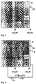
- Fig. 1
- Condition of oxidation without electric field. Oxygen ions diffuse from the gas-oxide interface to the metal-oxide interface. Electrons flow from the metal-oxide interface to the gas-oxide interface;
- Fig. 2
- Condition with impressed current. An external direct current provides electron flow to the metal-oxide interface. Therefore the sum of electron flow is zero and since the oxygen ion flux is in equilibrium with the electron flux the oxygen ion flux becomes zero;
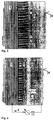
- Fig. 3
- The layers of a blade surface without electric field. In the substrate oxide scale and the TBC electrons flow outward and oxide ions flow inward during oxidation, the oxide scale is mainly Al2O3 and the TBC is mainly ZrO2;
- Fig. 4
- Application of an impressed current to provide opposite electron flow than in Fig. 3. An additional outside layer (anode) and a dc source is applied;
- Fig. 5
- A gas turbine blade protected by an impressed current. The dc power source can be placed in the rotor or outward the engine;
- Fig.6
- Electric scheme of the condition in the component surface.
- Only those elements that are essential for an understanding of the invention are shown.
- Referring now to the drawings, wherein like reference numerals designate identical or corresponding parts throughout the several views, in Figure 1 an electron conductive substrate 1 coated with an electrolyte 2 is exposed to air or oxygen. The electron conducting substrate 1 may consist of a Ni-base-superalloy, a refractory element or carbon. The electrolyte may consist of a metallic oxide like yttria-stabilized zirconia or hafnia. Substrates made out of Ni-base-superalloy may be single crystal (SX or SC), directional solidified (DS) or conventional cast (CC) components.
During oxidation an opposing flux of oxide ions and electrons takes place in the oxide scale. Therefore the oxide can be treated as a solid electrolyte. Wagner has done first considerations of an oxide scale to be an electrolytic medium in the 1930's and all investigations of today are still based on Wagers laws. - In following an electric field by polarizing the component to be protected negatively should be considered. The growth of an oxide scale depends on the flux of the oxygen ionsand on the opposing flux of electrons
 According to the reaction
- According to Figure 2 this can be realized by applying a closed circuit with a direct current source having the negative pole at the substrate 1 side B and the positive pole at the oxide surface 4 side A. The anode 3 should be high temperature resistant, have a good adherence, have the same thermal expansion coefficient as the electrolyte. The electrode should have preferably no porosity to prevent the substrate from molecular oxygen. The impressed current provides an external potential Eext in the opposite direction to the potential in the oxide. Is the external potential about the same order than the internal one the electron flow balance becomes minimal and therefore also the flux of oxygen ions. Equation 2 shows the oxide growth rate in dependence of the potentials.
- Potential due to oxidation (Nernst equation):
- Growth rate of an oxide scale which is primary ion conductive:
- E
- potential due to oxidation reaction
- dn/dt
- oxide growth rate (species per time)
- ΔG
- free energy of oxide formation
- Exert
- external applied potential
- n
- valence of ions of oxide
- tc, ta
- transfer numbers of cations and anions in the oxide
- F
- Faraday constant
- R
- Gas constant
- σ
- specific conductivity of the oxide
- T
- temperature
- Δx
- oxide scale thickness
- pO2 g
- oxygen partial pressure at oxide-gas interface
- r
- valence of ions of oxide
- pO2 i
- partial pressure at metal-oxide interface
- e
- electronic charge
- b
- number of oxygen ions in the oxide molecule
- For oxidation the flow of electrons and ions is an important mechanism. Figure 3 shows the conditions existing in a gas turbine component surface consisting of a substrate 1 of a Ni-base-superalloy, an optional bond coat 6 of MCrAlY, preferably NiCoCrAlY, a substrate oxide 7 and an electrolyte 2 of yttria-stabilized zirconia (ZrO2 with Y2O3), normally used as a thermal barrier coating (TBC).
- The main concern is the protection of the superalloy against severe oxidation. A NiCoCrAlY bond or overlay coating which forms a protective substrate oxide (alumina) scale generally provides this protection. The TBC is utilized to provide a thermal gradient to keep the blade surface relatively cool.
However, there are several limits for this kind of oxidation protection. The aluminum of the NiCoCrAlY coating will be consumed by the oxidation to maintain the protective alumina scale. Therefore there is a limit in oxidation resistance depending on the residual aluminum content of the coating. Another limit with respect to the TBC is the alumina scale thickness. Up to a alumina scale thickness of about 5 µm relatively good TBC adherence exists. Above 5 µm up to about 10 µm TBC-alumina integrity is not guarantied anymore. Above 10 µm the TBC spalls.
Through the control of the substrate oxide scale the oxidation protection can be enhanced. A control and decrease of the oxide growth will provide higher component lifetime by reducing oxidation and keeping the substrate-TBC integrity. - The rate of oxidation depends on the oxygen partial pressure at the substrate oxide - electrolyte interface 5, which in term depends on the amount of oxygen ions diffusing through the electrolyte layer 2.
- To reduce the oxidation of the substrate 1 or when applied of the bond coat 6 the oxygen ion transport in the electrolyte (TBC) has to be reduced. The advantageous nature of the TBC to be a highly ion conductive but poorly electron conductive material makes it possible to use the TBC as a solid electrolyte.
- According to Fig. 4 the change in electron flow rate can be realized by polarizing the base material with respect to an electrode 3 placed on top of the TBC. The substrate material 1 would be the cathode and the outer electrode an inert anode 3. As an anode material a perowskite oxide (La0.84Sr0.16MnO3) is useful. Oxides with perowskite structure are electron conductive to more than 1500 °C, high temperature resistant, relatively inert to the environment and they can be plasma sprayed or physical vapor deposited. Another advantage of the polarization-induced reduction of the oxygen partial pressure at the metal-oxide interface is the preferred formation of thermodynamically more stable oxides.
- The voltage necessary to stop oxidation can be estimated by using equation (1) with respect to the existence of a TBC as the ion conducting oxide (equation "modified (1)"). The voltage required to dissociate alumina would by in the range of -1.1 to -1.5 V, preferably -1,3 V. The applicable voltage is mainly depending on the temperature and the oxygen partial pressure according to equation modified (1).
- E
- potential due to oxidation reaction which equals necessary external potential
- ΔG
- free energy of substrate oxide formation (Al2O3)
- n
- valence of oxide ions in the TBC (ZrO2)
- F
- Faraday constant
- R
- Gas constant
- T
- temperature
- pO2 g
- oxygen partial pressure at TBC-gas interface
- pO2 d
- partial pressure for oxide dissociation of the substrate oxide (Al2O3)
- In practice a slightly lower voltage than - 1,3 V is more useful. Then oxidation is not completely stopped but strongly retarded and a thin alumina scale will be maintained. This is important to prevent oxidation in the case of TBC cracking and it keeps the TBC adherent to the substrate. However, even if there is no alumina and if the crack at the metal-TBC interface is not too wide it can be expected that the metal surface is still negatively charged. In this case oxygen will not form oxygen ions at this surface, which is necessary for oxidation. Porosity that is open from the surface of the zirconia coating to the metal substrate is disadvantageous.
Molecular oxygen diffuses then through the electrolyte. However, referring to TBC adherence the oxidation caused by molecular oxygen diffusion could be also advantageous. Differences of the coefficients of thermal expansion between the TBC and the perowskite anode are negligible compared to the difference between the TBC and the metallic substrate (see Table 1) and therefore of no concern.Physical data of the involved materials material thermal expansion coefficient at 1000 °C in 10-6 K-1 specific electric resistance at 1000 °C in Ω m MCrAlY (SV20) bond coating ∼ 21 38 x 10-6 (pure Ni, 900K) Al2O3 8 104 TBC 10 10 ZrO2 perowskite La0.84Sr0.16MnO3 same as zirconia 5 x 10⁻⁵ - The realization of the cathodic protection for gas turbine components depends on the component to be protected. Figure 5 shows as an example the utilization for a gas turbine blade airfoil 6 with a blade root 9 inserted in a rotor 10. The exact location of the DC source 11 depends on the design of the turbine and the type of component. In this case the DC source could be placed in the rotor 11 or outward the rotor with an electric connection to the blade airfoil 8 or root 9. The substrate is the cathode and the electrode is the anode. According to the location of the turbine component in the turbine, the temperature and the oxygen partial pressure at this location the voltage of the DC supply is adjusted to limit the growth of the substrate oxide.
For gas turbine vanes and burners, not shown, the application will be easier than for blades since these components are static and placed at the for the power source accessible engine casing. - The oxidation parameters change along the rotor longitudinal axis due to the changing temperature. Then it is useful to polarize the blades of one row with a certain potential and blades of another row with a different potential according to the temperature term in equation (1). This allows to adjust the substrate oxide scale 7 for every temperature and oxygen pressure in the turbine.
Because of economical reasons not every single blade and vane should be polarized by an own DC source. Several components can be connected to one DC power source.
The power required to protect a component can be calculated after the Ohm's law in equations (3), (4) and (5). For the calculation the resistance of the different materials have to be taken into consideration. In Figure 6 the electrical scheme of the component surface is shown. The potential necessary to retard oxidation (∼ 1,3 V) has to be maintained over the TBC and the oxide scale which forms beneath the TBC. The ranking of the resistance is R1 < R3 « R2 < R6. Since the resistance of the superalloys and the anode material are neglectable compared to the resistance of the TBC and the oxide scale (pure alumina assumed), only R6 and R2 according to Figure 6 are of importance. After Ohm the resistance's are additive in this scheme. The substrate oxide scale which should be retarded in growth should not become thicker than about 10µm, preferably not thicker than 5µm. With the said assumptions the power required to protect for example a turbine blade with an estimated surface for protection of 500 cm2 coated with a 300 µm thick TBC is 0,03 W after the calculation shown in equation (6). - P
- power
- ρ
- specific resistance of the TBC + oxide
- E
- external applied potential
- l
- thickness of the TBC + oxide scale
- I
- current
- A
- the surface area to be protected
- R
- resistance of the TBC + oxide
- A concern can be the high electric resistance of the substrate (alumina) oxide scale (104 Ωm) compared to the TBC (10 Ωm). This can lead to a major decrease of voltage in the alumina instead of having the potential across the TBC electrolyte. If the oxidation reaction only happens at the alumina-metal interface 5, having the major potential over the alumina scale is acceptable. When the oxidation reaction happens within the alumina oxide scale or even at the TBC-alumina interface the applied external voltage needs to be increased to provide the required potential of about 1,3 V over the TBC. However, it was found in experiments that the alumina growth follows Wagners laws, which means that oxide formation happens at the metal-oxide interface. Moreover, even increasing the external potential by a factor two (then 2,3 V) the required energy to protect the said blade would be only 0,09 W.
- The invention is of course not restricted to the exemplary embodiment shown and described. It can also be applied to steam turbine components.
- Obviously, numerous modifications and variations of the present invention are possible in light of the above teachings. It is therefore to be understood that within the scope of the appended claims, the invention may be practiced otherwise than as specifically described herein.
-
- 1
- substrate or cathode
- 2
- electrolyte or TBC
- 3
- anode
- 4
- oxide-gas interface or electrolyte-anode interface
- 5
- metal-oxide interface or substrate-oxide interface
- 6
- bond coating
- 7
- substrate oxide
- 8
- turbine blade airfoil
- 9
- turbine blade root
- 10
- Rotor
- 11
- DC supply
Claims (10)
- Turbine component comprising essentially an electron conductive substrate (1) and a solid ion conductive electrolyte (2),
wherein the electrolyte (2) is coated with an electron conductive electrode (3) and the substrate (1) is electrically connected with the electrode (3) through a DC supply (11), the substrate serving as cathode and the electrode as anode. - Turbine component as claimed in claim 1,
wherein the substrate (1) is a Ni-base-superalloy. - Turbine component as claimed in claim 2,
wherein the substrate is a single crystal cast component or a directionally cast component or a conventionally cast component. - Turbine component as claimed in one of the claims 1 to 3,
wherein a bond coat is located between the substrate and the electrolyte - Turbine component as claimed in claim 4,
wherein the bond coat consists of MCrALY alloy. - Turbine component as claimed in one of the claims 1 to 5,
wherein the electrolyte (2) is a yttria-stabilized zirconia and / or the electrode (3) is a perowskite. - Turbine component as claimed in one of the claims 1 to 6,
wherein the turbine component is a blade, a vane , a burner component. - A method to control the oxidation of a turbine component as claimed in one of the claims 1 to 7,
wherein the formation of the substrate oxide (7) is controlled by the voltage of an adjustable DC supply dependent on the temperature of the turbine component and dependent on the oxygen partial pressure of the environment. - A method as claimed in claim 8,
wherein the formation of the substrate oxide is limited to a thickness of ≤ 10 µm. - A method as claimed in claim 8,
wherein the formation of the substrate oxide is limited to a thickness of ≤ 5 µm.
Priority Applications (1)
| Application Number | Priority Date | Filing Date | Title |
|---|---|---|---|
| EP98810120A EP0936287A1 (en) | 1998-02-16 | 1998-02-16 | Turbine component and a method to control the oxidation of a turbine component |
Applications Claiming Priority (1)
| Application Number | Priority Date | Filing Date | Title |
|---|---|---|---|
| EP98810120A EP0936287A1 (en) | 1998-02-16 | 1998-02-16 | Turbine component and a method to control the oxidation of a turbine component |
Publications (1)
| Publication Number | Publication Date |
|---|---|
| EP0936287A1 true EP0936287A1 (en) | 1999-08-18 |
Family
ID=8235940
Family Applications (1)
| Application Number | Title | Priority Date | Filing Date |
|---|---|---|---|
| EP98810120A Withdrawn EP0936287A1 (en) | 1998-02-16 | 1998-02-16 | Turbine component and a method to control the oxidation of a turbine component |
Country Status (1)
| Country | Link |
|---|---|
| EP (1) | EP0936287A1 (en) |
Cited By (3)
| Publication number | Priority date | Publication date | Assignee | Title |
|---|---|---|---|---|
| DE10001620A1 (en) * | 2000-01-17 | 2001-07-19 | Abb Alstom Power Ch Ag | Process used for coating a blade of a gas turbine comprises exciting the base material during coating in an ultrasound frequency range using a transmitting head connected to a vibrator |
| EP1722011A1 (en) * | 2005-05-11 | 2006-11-15 | Siemens Aktiengesellschaft | Turbine component, electrical system with such a turbine component, combustor, turbine and method for reducing the corrosion in a turbine component. |
| FR3072456A1 (en) * | 2017-10-16 | 2019-04-19 | Safran Aircraft Engines | SYSTEM FOR PROTECTING CORROSION OF ALUMINUM PARTS OF A TURBOMACHINE |
Citations (2)
| Publication number | Priority date | Publication date | Assignee | Title |
|---|---|---|---|---|
| EP0455419A1 (en) * | 1990-04-30 | 1991-11-06 | General Electric Company | Coating steel articles |
| US5652044A (en) * | 1992-03-05 | 1997-07-29 | Rolls Royce Plc | Coated article |
-
1998
- 1998-02-16 EP EP98810120A patent/EP0936287A1/en not_active Withdrawn
Patent Citations (2)
| Publication number | Priority date | Publication date | Assignee | Title |
|---|---|---|---|---|
| EP0455419A1 (en) * | 1990-04-30 | 1991-11-06 | General Electric Company | Coating steel articles |
| US5652044A (en) * | 1992-03-05 | 1997-07-29 | Rolls Royce Plc | Coated article |
Non-Patent Citations (1)
| Title |
|---|
| COURTRIGHT: "Electrolytic Protection to Reduce High-Temperature Oxidation", OXID. MET., vol. 38, no. 3/4, 1992, pages 267 - 287, XP002073280 * |
Cited By (3)
| Publication number | Priority date | Publication date | Assignee | Title |
|---|---|---|---|---|
| DE10001620A1 (en) * | 2000-01-17 | 2001-07-19 | Abb Alstom Power Ch Ag | Process used for coating a blade of a gas turbine comprises exciting the base material during coating in an ultrasound frequency range using a transmitting head connected to a vibrator |
| EP1722011A1 (en) * | 2005-05-11 | 2006-11-15 | Siemens Aktiengesellschaft | Turbine component, electrical system with such a turbine component, combustor, turbine and method for reducing the corrosion in a turbine component. |
| FR3072456A1 (en) * | 2017-10-16 | 2019-04-19 | Safran Aircraft Engines | SYSTEM FOR PROTECTING CORROSION OF ALUMINUM PARTS OF A TURBOMACHINE |
Similar Documents
| Publication | Publication Date | Title |
|---|---|---|
| EP0848077B1 (en) | Thermal barrier coating systems and materials | |
| EP0992603B1 (en) | Thermal barrier coating systems and materials | |
| US6730422B2 (en) | Thermal barrier coatings with low thermal conductivity | |
| JP3051395B2 (en) | Method of overcoating to heat insulation coat and overcoated material | |
| EP1321542B1 (en) | Thermal barrier coating systems and materials | |
| RU2395624C2 (en) | Material and system of layers | |
| US7476450B2 (en) | Coating suitable for use as a bondcoat in a thermal barrier coating system | |
| US6123997A (en) | Method for forming a thermal barrier coating | |
| US6716539B2 (en) | Dual microstructure thermal barrier coating | |
| EP1400610A1 (en) | Thermal barrier coatings with low thermal conductivity comprising lanthanide sesquioxides | |
| MXPA06014620A (en) | Platinum modified nicocraly bondcoat for thermal barrier coating . | |
| KR100707789B1 (en) | Thermal barrier coating | |
| WO2005120824A2 (en) | Durable thermal barrier coating having low thermal conductivity | |
| KR100611723B1 (en) | Heat-resistant material Ti alloy material excellent in resistance to corrosion at high temperature and to oxidation | |
| US20100291302A1 (en) | Article protected by a thermal barrier coating having a group 2 or 3/group 5 stabilization-composition-enriched surface | |
| Vorkötter et al. | Oxide dispersion strengthened bond coats with higher alumina content: Oxidation resistance and influence on thermal barrier coating lifetime | |
| JP2006161808A (en) | Article protected by diffusion barrier layer and platinum group protective layer | |
| JP2003041358A (en) | Process for applying heat shielding coating system on metallic substrate | |
| EP0936287A1 (en) | Turbine component and a method to control the oxidation of a turbine component | |
| JP2001521992A (en) | Structural member subjected to hot gas impulse and method of forming coating on the structural member | |
| KR101166150B1 (en) | Durable thermal barrier coating having low thermal conductivity | |
| KR100270226B1 (en) | The heat protect coating and the same method | |
| CA1339403C (en) | Thermal barrier coating for superalloy components | |
| JP2004131814A (en) | Method for forming corrosion resistant coating for high-temperature equipment component, and corrosion resistant coating layer |
Legal Events
| Date | Code | Title | Description |
|---|---|---|---|
| PUAI | Public reference made under article 153(3) epc to a published international application that has entered the european phase |
Free format text: ORIGINAL CODE: 0009012 |
|
| AK | Designated contracting states |
Kind code of ref document: A1 Designated state(s): AT BE CH DE DK ES FI FR GB GR IE IT LI LU MC NL PT SE |
|
| AX | Request for extension of the european patent |
Free format text: AL;LT;LV;MK;RO;SI |
|
| AKX | Designation fees paid | ||
| REG | Reference to a national code |
Ref country code: DE Ref legal event code: 8566 |
|
| STAA | Information on the status of an ep patent application or granted ep patent |
Free format text: STATUS: THE APPLICATION IS DEEMED TO BE WITHDRAWN |
|
| 18D | Application deemed to be withdrawn |
Effective date: 20000219 |