EP0705725A1 - Air conditioning apparatus with film door - Google Patents
Air conditioning apparatus with film door Download PDFInfo
- Publication number
- EP0705725A1 EP0705725A1 EP95115809A EP95115809A EP0705725A1 EP 0705725 A1 EP0705725 A1 EP 0705725A1 EP 95115809 A EP95115809 A EP 95115809A EP 95115809 A EP95115809 A EP 95115809A EP 0705725 A1 EP0705725 A1 EP 0705725A1
- Authority
- EP
- European Patent Office
- Prior art keywords
- air
- casing
- flexible film
- door
- shaft
- Prior art date
- Legal status (The legal status is an assumption and is not a legal conclusion. Google has not performed a legal analysis and makes no representation as to the accuracy of the status listed.)
- Granted
Links
- 238000004378 air conditioning Methods 0.000 title claims abstract description 20
- 239000000463 material Substances 0.000 claims description 8
- 229920006269 PPS film Polymers 0.000 claims description 3
- 239000011248 coating agent Substances 0.000 claims description 3
- 238000000576 coating method Methods 0.000 claims description 3
- 239000004743 Polypropylene Substances 0.000 claims description 2
- 230000001143 conditioned effect Effects 0.000 claims description 2
- -1 polypropylene Polymers 0.000 claims description 2
- 229920001155 polypropylene Polymers 0.000 claims description 2
- 229920001296 polysiloxane Polymers 0.000 claims 1
- 238000007789 sealing Methods 0.000 description 6
- 238000004891 communication Methods 0.000 description 5
- 239000004677 Nylon Substances 0.000 description 3
- 229920001778 nylon Polymers 0.000 description 3
- 238000004804 winding Methods 0.000 description 3
- 239000000853 adhesive Substances 0.000 description 2
- 230000001070 adhesive effect Effects 0.000 description 2
- 239000000498 cooling water Substances 0.000 description 2
- 239000003507 refrigerant Substances 0.000 description 2
- 230000037303 wrinkles Effects 0.000 description 2
- 101000620653 Homo sapiens Serine/threonine-protein phosphatase 5 Proteins 0.000 description 1
- 102100022346 Serine/threonine-protein phosphatase 5 Human genes 0.000 description 1
- XUIMIQQOPSSXEZ-UHFFFAOYSA-N Silicon Chemical compound [Si] XUIMIQQOPSSXEZ-UHFFFAOYSA-N 0.000 description 1
- 238000010276 construction Methods 0.000 description 1
- 238000001816 cooling Methods 0.000 description 1
- 230000000694 effects Effects 0.000 description 1
- 229920006332 epoxy adhesive Polymers 0.000 description 1
- 239000004744 fabric Substances 0.000 description 1
- 238000009434 installation Methods 0.000 description 1
- 230000007935 neutral effect Effects 0.000 description 1
- 230000001953 sensory effect Effects 0.000 description 1
- 229910052710 silicon Inorganic materials 0.000 description 1
- 239000010703 silicon Substances 0.000 description 1
- 239000002210 silicon-based material Substances 0.000 description 1
- XLYOFNOQVPJJNP-UHFFFAOYSA-N water Substances O XLYOFNOQVPJJNP-UHFFFAOYSA-N 0.000 description 1
- 239000002759 woven fabric Substances 0.000 description 1
Images
Classifications
-
- F—MECHANICAL ENGINEERING; LIGHTING; HEATING; WEAPONS; BLASTING
- F24—HEATING; RANGES; VENTILATING
- F24F—AIR-CONDITIONING; AIR-HUMIDIFICATION; VENTILATION; USE OF AIR CURRENTS FOR SCREENING
- F24F13/00—Details common to, or for air-conditioning, air-humidification, ventilation or use of air currents for screening
- F24F13/08—Air-flow control members, e.g. louvres, grilles, flaps or guide plates
- F24F13/10—Air-flow control members, e.g. louvres, grilles, flaps or guide plates movable, e.g. dampers
- F24F13/12—Air-flow control members, e.g. louvres, grilles, flaps or guide plates movable, e.g. dampers built up of sliding members
-
- B—PERFORMING OPERATIONS; TRANSPORTING
- B60—VEHICLES IN GENERAL
- B60H—ARRANGEMENTS OF HEATING, COOLING, VENTILATING OR OTHER AIR-TREATING DEVICES SPECIALLY ADAPTED FOR PASSENGER OR GOODS SPACES OF VEHICLES
- B60H1/00—Heating, cooling or ventilating [HVAC] devices
- B60H1/00642—Control systems or circuits; Control members or indication devices for heating, cooling or ventilating devices
- B60H1/00664—Construction or arrangement of damper doors
- B60H1/00692—Damper doors moved by translation, e.g. curtain doors
-
- B—PERFORMING OPERATIONS; TRANSPORTING
- B60—VEHICLES IN GENERAL
- B60H—ARRANGEMENTS OF HEATING, COOLING, VENTILATING OR OTHER AIR-TREATING DEVICES SPECIALLY ADAPTED FOR PASSENGER OR GOODS SPACES OF VEHICLES
- B60H1/00—Heating, cooling or ventilating [HVAC] devices
- B60H1/00642—Control systems or circuits; Control members or indication devices for heating, cooling or ventilating devices
- B60H1/00664—Construction or arrangement of damper doors
- B60H2001/00728—Film doors
Definitions
- the present invention relates to an air conditioning apparatus, wherein a flexible film member having an opening for a passage of an air flow is moved in a casing for switching the direction of the air flow in the casing.
- Japanese Unexamined Patent Publication No. 5-310029 discloses an air conditioning apparatus which includes a flexible film member or film door having an opening for a passage of an air flow.
- the film member has a first and a second end connected to a driving and a driven shaft, respectively, which are rotatably supported in the casing.
- the casing defines therein a passageway for the air flow.
- the film member is arranged so that it is located opposite to air discharge outlets which are formed at the downstream end of the air passageway.
- a driving means is connected to the driving shaft for rotating the drive shaft, which causes the film door to be moved between a mode where an outlet is opened and a mode where another outlet is opened. As a result, a desired switching from mode to mode become possible.
- the flexural rigidity of the film door should be larger than a predetermined value, while, from the view point of the operating force, the flexural rigidity of the film door should be smaller than a predetermined value.
- An object of the present invention is to provide an air conditioning apparatus capable of obtaining a desired sealing between the film member and the casing.
- Another object of the present invention is to provide an air conditioning apparatus capable of obtaining as small an operating force as possible.
- Still another object of the present invention is to provide an air conditioning apparatus capable of harmonizing a requirement of an increased sealing between the film shaped member and the casing and a requirement of a reduced operating force.
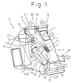
- Fig. 1 is a side view of an air conditioning apparatus according to the present invention.
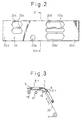
- Fig. 2 is a developed view of a mode switching door in Fig. 1.
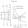
- Fig. 3 is a schematic view illustrating a relationship between the mode switching door and the casing.
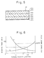
- Fig. 4 shows curves, with respect to the diameter of the shaft, of torque, rotating speed and output power.
- Fig. 5 is a cross-sectional view of the mode switching door, taken along a line V-V in Fig. 2.
- Fig. 6 shows curves, with respect to the diameter of the shaft, of operating force and leaked air amount.
- the air conditioning apparatus includes a casing 1 which forms an opening 2, to which a blower (not shown) is connected in such a manner that a flow of an air generated by the blower when the latter is driven is introduced, via the opening 2, into the casing 1.
- a blower (not shown) is connected in such a manner that a flow of an air generated by the blower when the latter is driven is introduced, via the opening 2, into the casing 1.
- a evaporator 3 Arranged inside the casing 1 along the direction of the air flow is an evaporator 3 and a heater core 4.
- the evaporator 3 has heat exchanging pipes (not shown) for the passage of a flow of a refrigerant.
- the evaporator 3 is a heat exchanger for executing a heat exchange operation between the air flow contacting the heat exchanging pipes and the flow of a refrigerant inside the pipes, so that the air flow is cooled.
- the evaporator 3 constructs a refrigerating apparatus for executing a refrigerating cycle.
- the heater core 4 has heat exchanging pipes (not shown) for a passage of a flow of an engine cooling water taken out from an engine cooling system.
- the heater core 4 is a heat exchanger for executing a heat exchange operation between the air flow contacting the pipes and the flow of the engine cooling water inside the pipes, so that the air flow is heated.
- the case 1 of the air conditioning apparatus forms, at its downstream end, a plurality of outlet openings (not shown), which are connected to ducts 5 to 10, which are opened to the cabin in such a manner that the air flows are discharged to the cabins at desired locations thereof.
- the duct 5 forms, at its downstream end, a defroster outlet (not shown), which is opened to the cabin at a location such that the air flow is discharged toward an inner surface of a wind shield (not shown).
- the duct 6 forms, at its downstream end, an upper-center outlet (not shown), which is opened to the cabin at a location such that the air flow is discharged toward an upper part of a driver or a passenger on a front seat at a side adjacent the center of the cabin.
- the duct 7 forms, at its downstream end, an upper-side outlet (not shown), which is opened to the cabin at a location such that the air flow is discharged toward an upper part of a driver or passenger on a side adjacent a side window.
- the duct 8 is, at its downstream end, a rear-upper outlet (not shown), which is opened to the cabin at a location such that the air flow is discharged to an upper part of a passenger on a rear seat of the cabin.
- the duct 9 is, at its downstream end, a lower-front outlet (not shown), which is opened to the cabin at a location such that the air flow is discharged to a lower part of a passenger on a front seat of the cabin.
- the duct 10 is, at its downstream end, a lower-rear outlet (not shown), which is opened to the cabin at a location such that the air flow is discharged to a lower part of a passenger on a rear seat of the cabin.
- An air mix door drive shaft 11 and an air mix door driven shaft 12 are rotatably supported by the casing 1, so that the shafts 11 and 12 extend transverse to the direction of the flow of the air in the passageway as shown by the arrows.
- a reference numeral 13 is an air mix door, which is formed as a flexible film and which has opposite ends along its length connected to the shafts 11 and 12, respectively.
- the shafts 11 and 12 are connected with each other by means of a pulley and belt mechanism schematically illustrated by a phantom line 50, so that a rotating movement is transmitted between the shafts 11 and 12.
- a rotating movement is one direction applied to the drive shaft 11 causes the film air mix door 13 to be taken out from the driven shaft 12 and to be wound on the drive shaft 11.
- a rotating movement in the opposite direction applied to the drive shaft 11 causes the film shaped air mix door 13 to be taken out from the drive shaft 11 and to be wound on the driven shaft 12.
- openings formed in the film shaped air mix door 13 are moved between a first position, where the opening is faced with the heater core 4, so that a hot air flow passageway 14 is created for allowing the cooled air flow from the evaporator 3 to he passed through the heater core 4, and a second position, where by-pass passageways 15 and 16 are created, so that the cooled air flow from the evaporator 3 by-passes the heater core 4.
- the air mix door 13 can take, between the first and second positions, a desired intermediate position, where a desired ratio is obtained between the flow passed through the hot air flow passageway 14 and the air flow passed through the by-pass passageways 15 and 16.
- the hot air passed through the passageway 14 and the cooled air passed through the by-pass passageways 15 and 16 are combined and discharged from the desired outlets.
- the temperature of the air after being combined is varied in accordance with the above ratio, i.e., the position of the opening of the air mix door 13 with respect to the passageways 14 to 16.
- the air mix door drive shaft 11 extends transverse to the flow of the air in the casing 1 and has an end located outside the casing 1 and connected to a rotary drive means such as a stepping motor 11-1.
- the stepping motor 11-1 can obtain a desired rotating position, which causes the opening of the air mix door 13 to be stopped at a desired position, so that the ratio between the flow passed through the hot air flow passageway 14 and the air flow passed through the by-pass passageways 15 and 16 is desirably controlled.
- the rotating position of the drive shaft 11 is controlled by a number of an electric pulses from a control circuit (not shown) realized as a microcomputer system.
- a mode switching door drive shaft 17, a mode switching door driven shaft 18, and an intermediate shaft 19 are also rotatably supported by the casing 1.
- a mode switching door 20 also made of an flexible film material has opposite ends along its length which are connected to the shafts 17 and 18, respectively.
- the shafts 17 and 18 are connected with each other by means of a pulley and belt mechanism schematically illustrated by a phantom line 52, so that a rotating movement is transmitted between the shafts 17 and 18.
- a rotating movement in one direction applied to the drive shaft 17 causes the film mode switching door 20 to be taken out from the driven shaft 18 and to be wound on the drive shaft 17.
- a rotating movement in the opposite direction applied to the drive shaft 17 causes the film mode switching door 20 to be taken out from the drive shaft 17 and to be wound on the driven shaft 18.
- the movement of the mode switching door 20 is guided by the intermediate shaft 19, so that an opening in the mode switching door 20 is moved between a first position, where the openings face a passageway to the ducts 6 and 7 to the upper outlets, a second position, where the openings face a passageway to the ducts 8 and 9 to the lower outlets, and a third position, where the opening faces a passageway to the duct 5 to the defroster outlet.
- the mode switching door drive shaft 17 has an end located outside the casing 1 and connected to a rotary drive means such as a stepping motor 17-1.
- the stepping motor 17-1 can obtain a desired rotating position, which causes the opening of the mode switching door 20 to be stopped at a desired position, so that the air flow is discharged from a desired outlet.
- the rotating position of the drive shaft 17 is controlled by a number of an electric pulses from a control circuit (not shown) realized as a microcomputer system.
- the casing 1 is formed with a cool air by-pass passageway 21 for directly introducing the cooled air into the ducts 6 and 7 directed to the upper outlets.
- a by-pass door 22 as a swing door type is arranged so that it is moved between a position as shown by a solid line where the by-pass passageway 21 is opened and a position as shown by a dotted line where the by-pass passageway 21 is closed. The opened position of the by-pass door 22 is obtained during a maximum cooled condition where the air mix door 13 is located so that the hot air passageway 14 is fully closed.
- the mode switching door 20 is formed with a plurality of openings 20a to 20c.
- the openings 20b and 20c are located at a distance.
- the openings 20b' and 20a are located at a distance.
- the mode switching door 20 has opposite ends 20d and 20e in the direction of its length. The first end 20d is connected to the driven shaft 18, while the second end 20e is connected to the driving shaft 17.
- the movement of the mode switching door 20 by means of the rotating moment of the shaft 17 causes the positional relationship to be varied between the openings 20a to 20c and the outlets to the ducts 6 to 9, thereby obtaining a desired mode corresponding to the rotating position of the stepping motor 17.
- the openings 20b are in communication with the duct 6 to the upper-center outlets, while the opening 20b' is in communication with the duct 7 to the upper-side outlets, so that the air flow is discharged from the upper outlets.
- the openings 20b are in communication with the ducts 8 and 9 to the lower outlets, while the opening 20a is in communication with the duct 7 to the upper-side outlets, so that the air flow is discharged from the lower outlets, while a small amount of air is discharged from the upper side outlets.
- the openings 20c are in communication with the duct 5 to the defroster outlet, so that an air flow is discharged from the defroster outlet.
- Fig. 3 schematically illustrates a relationship between the mode switching door 20, an inlet 5-1 of the defroster duct 5, and an inlet 6-1 of the upper-center outlet duct 6.
- the rotating movement of the shafts 17 and 18 causes the film door 20 to be moved, so that a desired switching of the direction of flow is obtained.
- the defroster mode is shown such that an air flow as shown by an arrow a1 is directed to the opening 5-1, and to the defroster duct 5 via the openings 20c in Fig. 2.
- the pressure of the air flow causes the flexible film door 20 to be deformed as shown by dotted lines, which causes the door 20 to be contacted with an edge of the inlet 5-1.
- Such a contact between the film door 20 and the edge of the inlet 5-1 prevents an air flow from leaking to the other inlets, such as the inlet 6-1 to the upper duct 6.
- the movement of the film door 20 as shown by the arrows f for obtaining a switching operation causes a frictional force to be generated between the film door 20 and the casing 1, thereby increasing the operational force of the drive motor required to obtain the switching operation.
- the frictional force is proportional to the friction coefficient between the film door 20 and the casing 1.
- a test was done for the mode switching door 20 of a width of 135.5 mm under a air flow pressure of 100 Pa and a speed of movement of the door of 4.4 seconds per a length of 160 mm.
- Fig. 4 is a result of the test. Namely, a curve A shows a relationship between a diameter of the shaft and the operating torque, a curve B shows a relationship between a diameter of the shaft and a rotating speed of the shaft, and a curve C shows a relationship between a diameter of the shaft and an output power of the drive motor.
- a value of diameter of the shaft smaller than 10 mm causes the outlet power of the drive motor 17-1 to rapidly increase, thereby requiring an increased size of the motor, which is not advantageous from the view point of an effective use of the limited space available in an automobile.
- a reduction in the output power of the drive motor 17-1 causes the winding speed to be greatly reduced, thereby reducing the response speed.
- An increase in the rotating speed for obviating this problem causes the operational noise to increase.
- the degree of the increase in the operational force is initially small and then gradually increases.
- an excessively large diameter of the shaft causes the size of the device to be increased, on one hand, and the resistance of the air flow to increase, on the other hand.
- a desired range of the diameter of the shaft is between 10 and 30 mm. In the shown embodiment, the diameter of the shaft is 16 mm.
- the frictional coefficient between the film door and the air conditioner casing 1 is determined by the material constructing the outer surface of the air conditioner casing 1, and the material constructing the outer surface of the film door.
- the air conditioner casing 1 is constructed of a polypropylene such as PP T 20 stipulated by the Japanese Industrial Standard (JIS) with outer coated layers made of a silicon material.
- JIS Japanese Industrial Standard
- a consideration should be taken so that a desired strength and a durability are obtained.
- a consideration should be taken so that the film door is not corroded by condensed water condensed at the evaporator attached to the film door.
- the frictional coefficient between the air conditional casing and the film shaped door is as small as 0.17, which can provide the maximum effect for suppressing an increase in the operational force caused by friction.
- the mode switching door 20 is constructed as a multi-layer film including a basic layer 201 as a PPS film of a thickness of 50 ⁇ m and of an elasticity modulus of 400 (kgf/mm2), intermediate layers 203 as nylon woven fabric of a thickness of 80 ⁇ m and of an elasticity modulus of 10 (kgf/mm2), the intermediate layers 203 being adhered to the basic layers 201 on both surfaces thereof by means of layers 202 of adhesive, such as NBR modified epoxy adhesive of a thickness of 5 ⁇ m and of an elasticity modulus of 1.0 (kgf/mm2), on the basic layer, and layers 204 of a silicon coating material of a thickness of 5 ⁇ m and of an elasticity modulus of 0.7 (kgf/mm2), applied to outer surfaces of the nylon layers 203.
- the mode switching door 20 is constructed as a five layer structure.
- the air mix door 13 is also constructed as a five layer structure similar to that of the mode switching door 20.
- a decrease in a flexural rigidity of the film shaped door causes a wrinkle to be generated, causing gaps to be generated between the film door and the casing, thereby allowing air to leak via the gap.
- the flexural rigidity of the door should be increased.
- a value of the flexural modulus of the film shaped door is maintained in a range which can harmonize a requirement that an operating force should be reduced and a requirement that a sealing ability should be increased.
- the inventor has found that a desired range of the value of the flexural rigidity of the film shaped door per width of 10 mm is between 1.1 ( ⁇ Nm2) and 2.5 ( ⁇ Nm2).
- the flexural rigidity has a value of 2.14 ( ⁇ Nm2).
- Zc ⁇ Ei ⁇ Z ⁇ dy ⁇ dz ⁇ Ei ⁇ dy ⁇ dz
- the value of the flexural rigidity EI of the multilayer film door per width of 10 mm, as calculated, is 2.14 ( ⁇ Nm2).
- curve A shows a relationship between the flexural rigidity of the mode switching door 20 and an operation force of the stepping motor 17-1 for causing the mode switching door 20 to be rotated.
- Curve B shows a relationship between the flexural rigidity of the mode switching door 20 and an amount of leaked air indicative of the sealing capability.
- the range of the flexural rigidity which is equal to 2.5 (kgf/mm2) or less allows that the operational force for rotating the shaft 17 of the stepping motor is equal to 50 (mN ⁇ m), which is effective for preventing the size of the stepping motor from being increased, which makes the system to be suitable for an installation in the limited space inside the vehicle, while obtaining a desired smooth or quick operation of the door 20 or 13.
- a range of the flexural rigidity which is equal to 1.1 (kgf/mm2) or more makes the leaked amount of air equal to 0.00175 (m2/s) or less.
- Table II shows a result of a test of a sensory test by a driver or passenger as to discomfort caused by the leaked air.
- Table II Leaked Air Amount (m3/s) Uncomfortability felt by Driver or Passenger ⁇ 0.0175 None > 0.0175 Yes but little ⁇ 0.0025 ⁇ 0.025 Yes
- the leaked air amount is suppressed so that it is equal to 0.0175 or less.
Landscapes
- Engineering & Computer Science (AREA)
- Mechanical Engineering (AREA)
- Chemical & Material Sciences (AREA)
- Combustion & Propulsion (AREA)
- General Engineering & Computer Science (AREA)
- Physics & Mathematics (AREA)
- Thermal Sciences (AREA)
- Air-Conditioning For Vehicles (AREA)
- Air-Flow Control Members (AREA)
Abstract
Description
- The present invention relates to an air conditioning apparatus, wherein a flexible film member having an opening for a passage of an air flow is moved in a casing for switching the direction of the air flow in the casing.
- Japanese Unexamined Patent Publication No. 5-310029 discloses an air conditioning apparatus which includes a flexible film member or film door having an opening for a passage of an air flow. The film member has a first and a second end connected to a driving and a driven shaft, respectively, which are rotatably supported in the casing. The casing defines therein a passageway for the air flow. The film member is arranged so that it is located opposite to air discharge outlets which are formed at the downstream end of the air passageway. Furthermore, a driving means is connected to the driving shaft for rotating the drive shaft, which causes the film door to be moved between a mode where an outlet is opened and a mode where another outlet is opened. As a result, a desired switching from mode to mode become possible.
- A test was done by the inventors of this application as to the air conditioning apparatus including a film door moved for switching a direction of an air flow in a casing. According to this test, it was firstly found that, when the flexural rigidity of the film door is too small, i.e., the film door is too flexible, an air flow pressure applied to the film door causes the latter to be wrinkled. Such an occurrence in the wrinkle causes a gap or gaps to be created between the film door and the casing, thereby allowing the air. flow to leak via the gap or gaps. Thus, the flexural rigidity of the film door should be larger than a predetermined value in order to obtain a desired level of a sealing characteristic.
- However, an excessively large value of the flexural rigidity would cause the torque for winding the film by a driving shaft to be excessively increased Namely, due to the increased rigidity, the film door is less flexible, which makes it difficult for the film door to be neatly wound on the drive shaft. As a result, a force for winding the film door on the drive shaft is inevitably increased. Such a requirement for increasing the drive torque can be met by increasing the power which is transmitted by the drive motor. However, such an increase in the drive power necessarily increase the size of the drive motor, which is disadvantageous in view of a limited space, in the air conditioning apparatus, available for storing the drive motor. In short, there is requirements that, in order to obtain a desired sealing ability, the flexural rigidity of the film door should be larger than a predetermined value, while, from the view point of the operating force, the flexural rigidity of the film door should be smaller than a predetermined value.
- An object of the present invention is to provide an air conditioning apparatus capable of obtaining a desired sealing between the film member and the casing.
- Another object of the present invention is to provide an air conditioning apparatus capable of obtaining as small an operating force as possible.
- Still another object of the present invention is to provide an air conditioning apparatus capable of harmonizing a requirement of an increased sealing between the film shaped member and the casing and a requirement of a reduced operating force.
- According to the present invention, an air conditioning apparatus for a compartment to be air conditioned is provided, comprising:
a casing defining therein a passageway for an air flow to be introduced into the compartment;
a flexible film member cooperating with the passageway for controlling the flow of the air;
a first shaft rotatably supported by the casing, while one of the ends of the flexible film member is connected to the first shaft, so that the member is wound on the first shaft;
a second shaft rotatably supported by the casing, while the other end of the flexible film member is connected to the second shaft, so that the member is wound on the second shaft, and;
means for generating a rotating movement applied to at least one of the first and second shafts so that the flexible film member is moved for causing a degree of a cooperation between the film member and the passageway to be varied;
the flexible film shaped member having a value of a flexural rigidity per width of 10 mm in a range between 1.1 and 2.5 (µNm²). - Fig. 1 is a side view of an air conditioning apparatus according to the present invention.
- Fig. 2 is a developed view of a mode switching door in Fig. 1.
- Fig. 3 is a schematic view illustrating a relationship between the mode switching door and the casing.
- Fig. 4 shows curves, with respect to the diameter of the shaft, of torque, rotating speed and output power.
- Fig. 5 is a cross-sectional view of the mode switching door, taken along a line V-V in Fig. 2.
- Fig. 6 shows curves, with respect to the diameter of the shaft, of operating force and leaked air amount.
- An embodiment of the present invention will be explained with reference to attached drawings directed to an application of the present invention to an air conditioning apparatus for a vehicle. The air conditioning apparatus includes a
casing 1 which forms anopening 2, to which a blower (not shown) is connected in such a manner that a flow of an air generated by the blower when the latter is driven is introduced, via theopening 2, into thecasing 1. Arranged inside thecasing 1 along the direction of the air flow is anevaporator 3 and a heater core 4. - The
evaporator 3 has heat exchanging pipes (not shown) for the passage of a flow of a refrigerant. Theevaporator 3 is a heat exchanger for executing a heat exchange operation between the air flow contacting the heat exchanging pipes and the flow of a refrigerant inside the pipes, so that the air flow is cooled. In a well known manner, together with a compressor, a condenser and an expansion valve, which are not shown in the drawing, theevaporator 3 constructs a refrigerating apparatus for executing a refrigerating cycle. - The heater core 4 has heat exchanging pipes (not shown) for a passage of a flow of an engine cooling water taken out from an engine cooling system. The heater core 4 is a heat exchanger for executing a heat exchange operation between the air flow contacting the pipes and the flow of the engine cooling water inside the pipes, so that the air flow is heated.
- The
case 1 of the air conditioning apparatus forms, at its downstream end, a plurality of outlet openings (not shown), which are connected toducts 5 to 10, which are opened to the cabin in such a manner that the air flows are discharged to the cabins at desired locations thereof. Namely, theduct 5 forms, at its downstream end, a defroster outlet (not shown), which is opened to the cabin at a location such that the air flow is discharged toward an inner surface of a wind shield (not shown). Theduct 6 forms, at its downstream end, an upper-center outlet (not shown), which is opened to the cabin at a location such that the air flow is discharged toward an upper part of a driver or a passenger on a front seat at a side adjacent the center of the cabin. Theduct 7 forms, at its downstream end, an upper-side outlet (not shown), which is opened to the cabin at a location such that the air flow is discharged toward an upper part of a driver or passenger on a side adjacent a side window. Furthermore, theduct 8 is, at its downstream end, a rear-upper outlet (not shown), which is opened to the cabin at a location such that the air flow is discharged to an upper part of a passenger on a rear seat of the cabin. The duct 9 is, at its downstream end, a lower-front outlet (not shown), which is opened to the cabin at a location such that the air flow is discharged to a lower part of a passenger on a front seat of the cabin. Finally, theduct 10 is, at its downstream end, a lower-rear outlet (not shown), which is opened to the cabin at a location such that the air flow is discharged to a lower part of a passenger on a rear seat of the cabin. - An air mix
door drive shaft 11 and an air mix door drivenshaft 12 are rotatably supported by thecasing 1, so that theshafts reference numeral 13 is an air mix door, which is formed as a flexible film and which has opposite ends along its length connected to theshafts shafts phantom line 50, so that a rotating movement is transmitted between theshafts drive shaft 11 causes the filmair mix door 13 to be taken out from the drivenshaft 12 and to be wound on thedrive shaft 11. Contrary to this, a rotating movement in the opposite direction applied to thedrive shaft 11 causes the film shapedair mix door 13 to be taken out from thedrive shaft 11 and to be wound on the drivenshaft 12. As a result, openings formed in the film shapedair mix door 13 are moved between a first position, where the opening is faced with the heater core 4, so that a hotair flow passageway 14 is created for allowing the cooled air flow from theevaporator 3 to he passed through the heater core 4, and a second position, where by-pass passageways evaporator 3 by-passes the heater core 4. Furthermore, theair mix door 13 can take, between the first and second positions, a desired intermediate position, where a desired ratio is obtained between the flow passed through the hotair flow passageway 14 and the air flow passed through the by-pass passageways passageway 14 and the cooled air passed through the by-pass passageways air mix door 13 with respect to thepassageways 14 to 16. - The air mix
door drive shaft 11 extends transverse to the flow of the air in thecasing 1 and has an end located outside thecasing 1 and connected to a rotary drive means such as a stepping motor 11-1. The stepping motor 11-1 can obtain a desired rotating position, which causes the opening of theair mix door 13 to be stopped at a desired position, so that the ratio between the flow passed through the hotair flow passageway 14 and the air flow passed through the by-pass passageways drive shaft 11 is controlled by a number of an electric pulses from a control circuit (not shown) realized as a microcomputer system. - Furthermore, a mode switching
door drive shaft 17, a mode switching door drivenshaft 18, and anintermediate shaft 19 are also rotatably supported by thecasing 1. Amode switching door 20 also made of an flexible film material has opposite ends along its length which are connected to theshafts shafts phantom line 52, so that a rotating movement is transmitted between theshafts drive shaft 17 causes the filmmode switching door 20 to be taken out from the drivenshaft 18 and to be wound on thedrive shaft 17. Contrary to this, a rotating movement in the opposite direction applied to thedrive shaft 17 causes the filmmode switching door 20 to be taken out from thedrive shaft 17 and to be wound on the drivenshaft 18. The movement of themode switching door 20 is guided by theintermediate shaft 19, so that an opening in themode switching door 20 is moved between a first position, where the openings face a passageway to theducts ducts 8 and 9 to the lower outlets, and a third position, where the opening faces a passageway to theduct 5 to the defroster outlet. - The mode switching
door drive shaft 17 has an end located outside thecasing 1 and connected to a rotary drive means such as a stepping motor 17-1. The stepping motor 17-1 can obtain a desired rotating position, which causes the opening of themode switching door 20 to be stopped at a desired position, so that the air flow is discharged from a desired outlet. In a well known manner, the rotating position of thedrive shaft 17 is controlled by a number of an electric pulses from a control circuit (not shown) realized as a microcomputer system. - Furthermore, the
casing 1 is formed with a cool air by-pass passageway 21 for directly introducing the cooled air into theducts pass door 22 as a swing door type is arranged so that it is moved between a position as shown by a solid line where the by-pass passageway 21 is opened and a position as shown by a dotted line where the by-pass passageway 21 is closed. The opened position of the by-pass door 22 is obtained during a maximum cooled condition where theair mix door 13 is located so that thehot air passageway 14 is fully closed. - As shown in a developed view in Fig. 2, the
mode switching door 20 is formed with a plurality ofopenings 20a to 20c. In more detail, on one side of themode switching door 20 along its length, theopenings mode switching door 20 along its length, theopenings 20b' and 20a are located at a distance. Furthermore, themode switching door 20 has opposite ends 20d and 20e in the direction of its length. Thefirst end 20d is connected to the drivenshaft 18, while thesecond end 20e is connected to the drivingshaft 17. The movement of themode switching door 20 by means of the rotating moment of theshaft 17 causes the positional relationship to be varied between theopenings 20a to 20c and the outlets to theducts 6 to 9, thereby obtaining a desired mode corresponding to the rotating position of the steppingmotor 17. Namely, during an upper mode, theopenings 20b are in communication with theduct 6 to the upper-center outlets, while theopening 20b' is in communication with theduct 7 to the upper-side outlets, so that the air flow is discharged from the upper outlets. During a lower mode, theopenings 20b are in communication with theducts 8 and 9 to the lower outlets, while theopening 20a is in communication with theduct 7 to the upper-side outlets, so that the air flow is discharged from the lower outlets, while a small amount of air is discharged from the upper side outlets. During a defroster mode, theopenings 20c are in communication with theduct 5 to the defroster outlet, so that an air flow is discharged from the defroster outlet. - Fig. 3 schematically illustrates a relationship between the
mode switching door 20, an inlet 5-1 of thedefroster duct 5, and an inlet 6-1 of the upper-center outlet duct 6. The rotating movement of theshafts film door 20 to be moved, so that a desired switching of the direction of flow is obtained. In Fig. 3, the defroster mode is shown such that an air flow as shown by an arrow a₁ is directed to the opening 5-1, and to thedefroster duct 5 via theopenings 20c in Fig. 2. The pressure of the air flow causes theflexible film door 20 to be deformed as shown by dotted lines, which causes thedoor 20 to be contacted with an edge of the inlet 5-1. Such a contact between thefilm door 20 and the edge of the inlet 5-1 prevents an air flow from leaking to the other inlets, such as the inlet 6-1 to theupper duct 6. However, due to such a contact, the movement of thefilm door 20 as shown by the arrows f for obtaining a switching operation causes a frictional force to be generated between thefilm door 20 and thecasing 1, thereby increasing the operational force of the drive motor required to obtain the switching operation. The frictional force is proportional to the friction coefficient between thefilm door 20 and thecasing 1. - In addition to the friction between the film door and the casing, there are other factors which can increase the operational force, such as a bearing loss at the
drive shaft 17, a force for flexing the film at thedrive shaft 17, a rotating force transmitting loss between the drive and drivenshafts intermediate shaft 19, a force for flexing the film at theintermediate shaft 19, a frictional force between the film door and theintermediate shaft 19, and the diameters of theshafts mode switching door 20 of a width of 135.5 mm under a air flow pressure of 100 Pa and a speed of movement of the door of 4.4 seconds per a length of 160 mm. Fig. 4 is a result of the test. Namely, a curve A shows a relationship between a diameter of the shaft and the operating torque, a curve B shows a relationship between a diameter of the shaft and a rotating speed of the shaft, and a curve C shows a relationship between a diameter of the shaft and an output power of the drive motor. As will be understood from the curves, a value of diameter of the shaft smaller than 10 mm causes the outlet power of the drive motor 17-1 to rapidly increase, thereby requiring an increased size of the motor, which is not advantageous from the view point of an effective use of the limited space available in an automobile. A reduction in the output power of the drive motor 17-1 causes the winding speed to be greatly reduced, thereby reducing the response speed. An increase in the rotating speed for obviating this problem causes the operational noise to increase. - In the region where the diameter of the shaft is larger than 10 mm, the degree of the increase in the operational force is initially small and then gradually increases. However, an excessively large diameter of the shaft causes the size of the device to be increased, on one hand, and the resistance of the air flow to increase, on the other hand. Thus, a desired range of the diameter of the shaft is between 10 and 30 mm. In the shown embodiment, the diameter of the shaft is 16 mm.
- Now, the frictional coefficient between the film door and the
air conditioner casing 1 will be discussed. The frictional coefficient is determined by the material constructing the outer surface of theair conditioner casing 1, and the material constructing the outer surface of the film door. In the embodiment of the present invention, theair conditioner casing 1 is constructed of a polypropylene such asPP T 20 stipulated by the Japanese Industrial Standard (JIS) with outer coated layers made of a silicon material. As to the selection of a material constructing the air conditioner casing, a consideration should be taken so that a desired strength and a durability are obtained. As to the selection of a material constructing the film door, a consideration should be taken so that the film door is not corroded by condensed water condensed at the evaporator attached to the film door. According to the present invention, the frictional coefficient between the air conditional casing and the film shaped door is as small as 0.17, which can provide the maximum effect for suppressing an increase in the operational force caused by friction. - As shown in Fig. 5, the
mode switching door 20 is constructed as a multi-layer film including abasic layer 201 as a PPS film of a thickness of 50 µm and of an elasticity modulus of 400 (kgf/mm²),intermediate layers 203 as nylon woven fabric of a thickness of 80 µm and of an elasticity modulus of 10 (kgf/mm²), theintermediate layers 203 being adhered to thebasic layers 201 on both surfaces thereof by means oflayers 202 of adhesive, such as NBR modified epoxy adhesive of a thickness of 5 µm and of an elasticity modulus of 1.0 (kgf/mm²), on the basic layer, and layers 204 of a silicon coating material of a thickness of 5 µm and of an elasticity modulus of 0.7 (kgf/mm²), applied to outer surfaces of the nylon layers 203. In other words, themode switching door 20 is constructed as a five layer structure. - The
air mix door 13 is also constructed as a five layer structure similar to that of themode switching door 20. - Now, the flexural rigidity of the film door will be discussed. An increase in a flexural rigidity of the film door makes it difficult for the door to be wound on the shaft, thereby increasing the operational force of the motor. In other words, a reduction of the value of the flexural rigidity is desirable for obtaining a reduced operational force. Contrary to this, a decrease in a flexural rigidity of the film shaped door causes a wrinkle to be generated, causing gaps to be generated between the film door and the casing, thereby allowing air to leak via the gap. In order to reduce the amount of such a leakage of air, the flexural rigidity of the door should be increased. Thus, it is important that a value of the flexural modulus of the film shaped door is maintained in a range which can harmonize a requirement that an operating force should be reduced and a requirement that a sealing ability should be increased. According to the present invention, the inventor has found that a desired range of the value of the flexural rigidity of the film shaped door per width of 10 mm is between 1.1 (µNm²) and 2.5 (µNm²). In the illustrated embodiment, the flexural rigidity has a value of 2.14 (µNm²). A value of the flexural rigidity EI of the film shaped door of the multi-layer structure as shown in Fig. 5 is calculated by


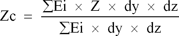
Table I Layers Young's Modulus (kgf/mm²) Thickness (µm) PPS film (201) 400 50 Nylon fabric (203) 10 80 NBR adhesive (202) 1.0 5 Coating (204) 0.7 5 - The value of the flexural rigidity EI of the multilayer film door per width of 10 mm, as calculated, is 2.14 (µNm²).
- In Fig. 6, curve A shows a relationship between the flexural rigidity of the
mode switching door 20 and an operation force of the stepping motor 17-1 for causing themode switching door 20 to be rotated. Curve B shows a relationship between the flexural rigidity of themode switching door 20 and an amount of leaked air indicative of the sealing capability. The range of the flexural rigidity, which is equal to 2.5 (kgf/mm²) or less allows that the operational force for rotating theshaft 17 of the stepping motor is equal to 50 (mN × m), which is effective for preventing the size of the stepping motor from being increased, which makes the system to be suitable for an installation in the limited space inside the vehicle, while obtaining a desired smooth or quick operation of thedoor Table II Leaked Air Amount (m³/s) Uncomfortability felt by Driver or Passenger ≦ 0.0175 None > 0.0175 Yes but little < 0.0025 ≧ 0.025 Yes - In view of the above, in order to prevent a driver or passenger from feeling discomfort caused by leaked air, it is required that the leaked air amount is suppressed so that it is equal to 0.0175 or less.
Claims (6)
- An air conditioning apparatus for a compartment to be air conditioned comprising:
a casing defining therein a passageway for an air flow to be introduced into the compartment;
a flexible film member cooperating with the passageway for controlling the flow of the air;
a first shaft rotatably supported by the casing, while one of the ends of the flexible film member is connected to the first shaft, so that the member is wound on the first shaft;
a second shaft rotatably supported by the casing, while the other end of the flexible film member is connected to the second shaft, so that the member is wound on the second shaft, and;
means for generating a rotating movement applied to at least one of the first and second shafts so that the flexible film member is moved for causing a degree of a cooperation between the film member and the passageway to be varied;
the flexible film member having a value of a flexural rigidity per width of 10 mm in a range between 1.1 and 2.5 (µNm²). - An air conditioning apparatus according to claim 1, wherein a blower is arranged in the casing for generating air flow in the passageway;
wherein said flexible film member with a pair of ends spaced along a length of the member, and having a first portion with an opening for a passage of the air flow and a second portion spaced from the first portion along the length of the member of preventing the air flow from being passed;
wherein said casing being, at a location of the passageway, formed with a seat portion defining an annular inner edge which cooperates with the flexible film member, and;
wherein the flexible film member being moved with respect to the seat portion between a first position where the first portion is seated on the seat portion for allowing a passage of the air flow and a second position where the second portion is seated on the seat portion for preventing a passage of the air flow. - An air conditioning apparatus according to claim 1, wherein said rotating movement generating means comprise an electric motor and a transmitting means for transmitting rotating movement between the first and second shafts.
- An air conditioning apparatus according to claim 1, wherein the first and second shafts have a diameter of a value in a range between 10 and 30 mm.
- An air conditioning apparatus according to claim 1, wherein said flexible film shaped member includes a PPS film.
- An air conditioning apparatus according to claim 2, wherein said casing is, at least, at a location of the edge of the seat portion, made of a polypropylene, and wherein the flexible film shaped member has at a surface contacting the edge of the seat portion, a coating made of a silicone material.
Applications Claiming Priority (2)
| Application Number | Priority Date | Filing Date | Title |
|---|---|---|---|
| JP24394194 | 1994-10-07 | ||
| JP243941/94 | 1994-10-07 |
Publications (2)
| Publication Number | Publication Date |
|---|---|
| EP0705725A1 true EP0705725A1 (en) | 1996-04-10 |
| EP0705725B1 EP0705725B1 (en) | 1999-03-24 |
Family
ID=17111319
Family Applications (1)
| Application Number | Title | Priority Date | Filing Date |
|---|---|---|---|
| EP95115809A Expired - Lifetime EP0705725B1 (en) | 1994-10-07 | 1995-10-06 | Air conditioning apparatus with film door |
Country Status (3)
| Country | Link |
|---|---|
| US (1) | US5653630A (en) |
| EP (1) | EP0705725B1 (en) |
| DE (1) | DE69508516T2 (en) |
Cited By (9)
| Publication number | Priority date | Publication date | Assignee | Title |
|---|---|---|---|---|
| FR2761015A1 (en) * | 1997-03-18 | 1998-09-25 | Valeo Climatisation | Heater/ventilator control for vehicle passenger compartment |
| EP0895043A3 (en) * | 1997-07-31 | 1999-10-13 | Samsung Electronics Co., Ltd. | Refrigerator |
| EP0989004A3 (en) * | 1998-08-28 | 2001-09-19 | Delphi Technologies, Inc. | Compact automotive air conditioning module |
| US6383959B1 (en) | 2000-03-23 | 2002-05-07 | Milliken & Company | Fabric for diverting air flow in an automotive air conditioning system |
| EP1346859A2 (en) | 2002-03-23 | 2003-09-24 | Behr GmbH & Co. | Control device for a heating and/or air conditioning unit |
| DE10337323A1 (en) * | 2002-08-16 | 2004-06-09 | Behr Gmbh & Co. Kg | Control device used in a heating or air-conditioning system for controlling air flow in motor vehicles comprises a frame having a housing with hollow bodies receiving the drive shaft or deviating shaft of a roller louver |
| WO2004074020A2 (en) | 2003-02-18 | 2004-09-02 | Delphi Technologies, Inc. | Hvac system having a film valve |
| FR2859136A1 (en) * | 2003-08-28 | 2005-03-04 | Valeo Climatisation | Air mixer shutter for duct in motor vehicle heating/air conditioning system is made from thin elastic film with slits that open when tensioned |
| EP0911196B2 (en) † | 1997-09-29 | 2009-02-18 | Calsonic Kansei Corporation | Heating, ventilation, and air conditioning unit for automotive vehicles |
Families Citing this family (32)
| Publication number | Priority date | Publication date | Assignee | Title |
|---|---|---|---|---|
| JP3493093B2 (en) * | 1996-02-16 | 2004-02-03 | 本田技研工業株式会社 | Damper mechanism for vehicle air conditioner |
| FR2746715B1 (en) * | 1996-03-29 | 1998-05-22 | Valeo Climatisation | AIR FLOW CONTROL DEVICE, PARTICULARLY FOR A VEHICLE HEATING AND / OR AIR CONDITIONING INSTALLATION |
| FR2746716B1 (en) * | 1996-03-29 | 1998-05-22 | Valeo Climatisation | DEVICE FOR CONTROLLING AN AIRFLOW, PARTICULARLY FOR A HEATING AND / OR AIR CONDITIONING SYSTEM OF A MOTOR VEHICLE |
| US5881558A (en) * | 1996-04-03 | 1999-03-16 | Mitsubishi Heavy Industries, Ltd. | Air conditioning apparatus for vehicles |
| JP4048587B2 (en) * | 1998-02-19 | 2008-02-20 | 株式会社デンソー | Air conditioner for vehicles |
| US5934361A (en) * | 1998-02-27 | 1999-08-10 | General Motors Corporation | Automotive heating and air conditioning assembly with improved air flow and temperature control |
| US5964658A (en) * | 1998-03-31 | 1999-10-12 | Denso Corporation | Air passage opening/closing system for air conditioning apparatus |
| US6074294A (en) * | 1999-04-23 | 2000-06-13 | Delphi Technologies, Inc. | Single shaft film valve drive |
| US7927684B2 (en) * | 2000-01-19 | 2011-04-19 | Saint-Gobain Performance Plastics Corporation | Low coefficient of friction polymer film |
| US6273811B1 (en) | 2000-01-21 | 2001-08-14 | Delphi Technologies, Inc. | Dual film belt vehicle air conditioning system |
| US6368207B1 (en) | 2000-08-25 | 2002-04-09 | Delphi Technologies, Inc. | Automotive heating, ventilating and air conditioning module with improved air mixing |
| JP3951926B2 (en) * | 2002-03-11 | 2007-08-01 | 株式会社デンソー | Air passage opening and closing device and vehicle air conditioner |
| US6905985B1 (en) * | 2002-11-21 | 2005-06-14 | Highland Industries, Inc. | Fabric film for automotive heaters |
| JP4093031B2 (en) * | 2002-11-28 | 2008-05-28 | 株式会社デンソー | Fluid path control device |
| DE10258025B4 (en) * | 2002-12-12 | 2006-09-21 | Daimlerchrysler Ag | air conditioning |
| JP2004345363A (en) * | 2003-03-18 | 2004-12-09 | Calsonic Kansei Corp | Air duct for vehicle |
| DE102004027689A1 (en) * | 2004-06-07 | 2006-01-05 | Denso Automotive Deutschland Gmbh | Air conditioning for a motor vehicle |
| US7371161B2 (en) * | 2004-08-27 | 2008-05-13 | Delphi Technologies, Inc. | Sliding film valve driven at edge |
| US7527551B2 (en) | 2004-08-27 | 2009-05-05 | Delphi Technologies, Inc. | Sliding valve, especially for heating, ventilation and air conditioning system |
| JP4363283B2 (en) * | 2004-09-13 | 2009-11-11 | 株式会社デンソー | Air passage opening and closing device |
| US7074122B2 (en) * | 2004-11-03 | 2006-07-11 | Visteon Global Technologies, Inc. | Air stream mixing conduit in an air handling module |
| JP2006168584A (en) * | 2004-12-16 | 2006-06-29 | Denso Corp | Air passage changing device and vehicular air-conditioner |
| US7503234B2 (en) * | 2005-05-26 | 2009-03-17 | Delphi Technologies, Inc. | One lever tilt and telescope mechanism |
| US7520804B2 (en) * | 2005-11-30 | 2009-04-21 | Ford Motor Company | Climate control system having noise reduction door |
| US20080146138A1 (en) * | 2006-12-15 | 2008-06-19 | Valeo Climate Control Corp. | Automotive HVAC with integral dividing wall connectors |
| USD577110S1 (en) * | 2007-05-21 | 2008-09-16 | Mcdonald Michael | Air cleaner |
| US20090061753A1 (en) * | 2007-08-31 | 2009-03-05 | Gm Global Technology Operations, Inc. | System for cooling engine electronics |
| DE102008004188A1 (en) | 2008-01-11 | 2009-07-16 | Behr Gmbh & Co. Kg | Rolling band for control device of e.g. air conditioning system, has drawing units running in longitudinal direction of band and arranged distributedly over width of rolling band, and coating forming upper side and lower side of band |
| CN101968008B (en) * | 2010-09-30 | 2013-07-17 | 奇瑞汽车股份有限公司 | Error correcting method for step out of stepping motor |
| KR101592734B1 (en) * | 2014-07-11 | 2016-02-15 | 현대자동차주식회사 | Heat pump apparatus for vehicle |
| CN111002787B (en) * | 2018-10-08 | 2023-04-11 | 翰昂汽车零部件有限公司 | Member with through hole and vehicle air conditioner provided with same |
| US11719463B2 (en) | 2020-08-24 | 2023-08-08 | Denso International America, Inc. | Film door belt fluid flow control system |
Citations (4)
| Publication number | Priority date | Publication date | Assignee | Title |
|---|---|---|---|---|
| EP0459473A1 (en) * | 1990-05-29 | 1991-12-04 | Nippondenso Co., Ltd. | Automotive air-conditioner |
| US5105730A (en) * | 1990-12-17 | 1992-04-21 | Ford Motor Company | Air distribution apparatus for an automotive vehicle |
| EP0545320A1 (en) * | 1991-11-29 | 1993-06-09 | Nippondenso Co., Ltd. | Air passage changeover device |
| JPH05310029A (en) | 1992-05-08 | 1993-11-22 | Nippondenso Co Ltd | Air passage changeover device |
-
1995
- 1995-10-06 DE DE69508516T patent/DE69508516T2/en not_active Expired - Lifetime
- 1995-10-06 US US08/539,905 patent/US5653630A/en not_active Expired - Lifetime
- 1995-10-06 EP EP95115809A patent/EP0705725B1/en not_active Expired - Lifetime
Patent Citations (5)
| Publication number | Priority date | Publication date | Assignee | Title |
|---|---|---|---|---|
| EP0459473A1 (en) * | 1990-05-29 | 1991-12-04 | Nippondenso Co., Ltd. | Automotive air-conditioner |
| US5105730A (en) * | 1990-12-17 | 1992-04-21 | Ford Motor Company | Air distribution apparatus for an automotive vehicle |
| US5105730B1 (en) * | 1990-12-17 | 1995-02-14 | Ford Motor Co | Air distribution apparatus for an automotive device |
| EP0545320A1 (en) * | 1991-11-29 | 1993-06-09 | Nippondenso Co., Ltd. | Air passage changeover device |
| JPH05310029A (en) | 1992-05-08 | 1993-11-22 | Nippondenso Co Ltd | Air passage changeover device |
Cited By (10)
| Publication number | Priority date | Publication date | Assignee | Title |
|---|---|---|---|---|
| FR2761015A1 (en) * | 1997-03-18 | 1998-09-25 | Valeo Climatisation | Heater/ventilator control for vehicle passenger compartment |
| EP0895043A3 (en) * | 1997-07-31 | 1999-10-13 | Samsung Electronics Co., Ltd. | Refrigerator |
| EP0911196B2 (en) † | 1997-09-29 | 2009-02-18 | Calsonic Kansei Corporation | Heating, ventilation, and air conditioning unit for automotive vehicles |
| EP0989004A3 (en) * | 1998-08-28 | 2001-09-19 | Delphi Technologies, Inc. | Compact automotive air conditioning module |
| US6383959B1 (en) | 2000-03-23 | 2002-05-07 | Milliken & Company | Fabric for diverting air flow in an automotive air conditioning system |
| EP1346859A2 (en) | 2002-03-23 | 2003-09-24 | Behr GmbH & Co. | Control device for a heating and/or air conditioning unit |
| DE10213177A1 (en) * | 2002-03-23 | 2003-10-02 | Behr Gmbh & Co | Control device for heating and / or air conditioning systems |
| DE10337323A1 (en) * | 2002-08-16 | 2004-06-09 | Behr Gmbh & Co. Kg | Control device used in a heating or air-conditioning system for controlling air flow in motor vehicles comprises a frame having a housing with hollow bodies receiving the drive shaft or deviating shaft of a roller louver |
| WO2004074020A2 (en) | 2003-02-18 | 2004-09-02 | Delphi Technologies, Inc. | Hvac system having a film valve |
| FR2859136A1 (en) * | 2003-08-28 | 2005-03-04 | Valeo Climatisation | Air mixer shutter for duct in motor vehicle heating/air conditioning system is made from thin elastic film with slits that open when tensioned |
Also Published As
| Publication number | Publication date |
|---|---|
| US5653630A (en) | 1997-08-05 |
| EP0705725B1 (en) | 1999-03-24 |
| DE69508516D1 (en) | 1999-04-29 |
| DE69508516T2 (en) | 1999-07-15 |
Similar Documents
| Publication | Publication Date | Title |
|---|---|---|
| EP0705725A1 (en) | Air conditioning apparatus with film door | |
| EP0773121B1 (en) | Air passage switching device and air conditioning apparatus using the same | |
| US6508703B1 (en) | Air passage opening/closing device for vehicle air conditioner | |
| US7779900B2 (en) | Air conditioner for vehicle use | |
| US5676595A (en) | Air duct selector and automotive air conditioner | |
| US7159651B2 (en) | Air conditioner for vehicle use | |
| US6568468B1 (en) | Air conditioning apparatus for vehicle | |
| EP1044833B1 (en) | Air conditioning apparatus for vehicle | |
| US5154223A (en) | Automotive air-conditioner having a film damper | |
| US6569009B2 (en) | Air passage opening and closing system and air conditioning system having the same | |
| JP3285123B2 (en) | Vehicle heating system | |
| JP3646365B2 (en) | Automotive air conditioner | |
| KR980008661A (en) | Case of air conditioner | |
| US5632672A (en) | Air conditioning apparatus with film member | |
| US5964658A (en) | Air passage opening/closing system for air conditioning apparatus | |
| JP4093031B2 (en) | Fluid path control device | |
| EP1630014B1 (en) | Sliding film valve driven at edge | |
| JP3596114B2 (en) | Air conditioner | |
| JP3284726B2 (en) | Air passage switching device | |
| JPH10338019A (en) | Air conditioner for vehicle | |
| JPS5855056Y2 (en) | Vehicle air conditioner | |
| JP3246121B2 (en) | Air conditioner | |
| JP3671535B2 (en) | Air passage switching device and vehicle air conditioner | |
| JP3208979B2 (en) | Vehicle air conditioner | |
| JPH09132021A (en) | Air conditioner |
Legal Events
| Date | Code | Title | Description |
|---|---|---|---|
| PUAI | Public reference made under article 153(3) epc to a published international application that has entered the european phase |
Free format text: ORIGINAL CODE: 0009012 |
|
| AK | Designated contracting states |
Kind code of ref document: A1 Designated state(s): DE FR GB |
|
| 17P | Request for examination filed |
Effective date: 19960418 |
|
| RAP1 | Party data changed (applicant data changed or rights of an application transferred) |
Owner name: DENSO CORPORATION |
|
| 17Q | First examination report despatched |
Effective date: 19970317 |
|
| GRAG | Despatch of communication of intention to grant |
Free format text: ORIGINAL CODE: EPIDOS AGRA |
|
| GRAG | Despatch of communication of intention to grant |
Free format text: ORIGINAL CODE: EPIDOS AGRA |
|
| GRAH | Despatch of communication of intention to grant a patent |
Free format text: ORIGINAL CODE: EPIDOS IGRA |
|
| GRAH | Despatch of communication of intention to grant a patent |
Free format text: ORIGINAL CODE: EPIDOS IGRA |
|
| GRAA | (expected) grant |
Free format text: ORIGINAL CODE: 0009210 |
|
| AK | Designated contracting states |
Kind code of ref document: B1 Designated state(s): DE FR GB |
|
| REF | Corresponds to: |
Ref document number: 69508516 Country of ref document: DE Date of ref document: 19990429 |
|
| ET | Fr: translation filed | ||
| PLBE | No opposition filed within time limit |
Free format text: ORIGINAL CODE: 0009261 |
|
| STAA | Information on the status of an ep patent application or granted ep patent |
Free format text: STATUS: NO OPPOSITION FILED WITHIN TIME LIMIT |
|
| 26N | No opposition filed | ||
| REG | Reference to a national code |
Ref country code: GB Ref legal event code: IF02 |
|
| PGFP | Annual fee paid to national office [announced via postgrant information from national office to epo] |
Ref country code: GB Payment date: 20071003 Year of fee payment: 13 |
|
| GBPC | Gb: european patent ceased through non-payment of renewal fee |
Effective date: 20081006 |
|
| PG25 | Lapsed in a contracting state [announced via postgrant information from national office to epo] |
Ref country code: GB Free format text: LAPSE BECAUSE OF NON-PAYMENT OF DUE FEES Effective date: 20081006 |
|
| PGFP | Annual fee paid to national office [announced via postgrant information from national office to epo] |
Ref country code: DE Payment date: 20131021 Year of fee payment: 19 Ref country code: FR Payment date: 20131022 Year of fee payment: 19 |
|
| REG | Reference to a national code |
Ref country code: DE Ref legal event code: R119 Ref document number: 69508516 Country of ref document: DE |
|
| PG25 | Lapsed in a contracting state [announced via postgrant information from national office to epo] |
Ref country code: DE Free format text: LAPSE BECAUSE OF NON-PAYMENT OF DUE FEES Effective date: 20150501 |
|
| REG | Reference to a national code |
Ref country code: FR Ref legal event code: ST Effective date: 20150630 |
|
| PG25 | Lapsed in a contracting state [announced via postgrant information from national office to epo] |
Ref country code: FR Free format text: LAPSE BECAUSE OF NON-PAYMENT OF DUE FEES Effective date: 20141031 |