EP0705668A1 - Knife ring cutter - Google Patents
Knife ring cutter Download PDFInfo
- Publication number
- EP0705668A1 EP0705668A1 EP95107833A EP95107833A EP0705668A1 EP 0705668 A1 EP0705668 A1 EP 0705668A1 EP 95107833 A EP95107833 A EP 95107833A EP 95107833 A EP95107833 A EP 95107833A EP 0705668 A1 EP0705668 A1 EP 0705668A1
- Authority
- EP
- European Patent Office
- Prior art keywords
- knife
- ring
- wear plate
- projection
- carrying
- Prior art date
- Legal status (The legal status is an assumption and is not a legal conclusion. Google has not performed a legal analysis and makes no representation as to the accuracy of the status listed.)
- Withdrawn
Links
Images
Classifications
-
- B—PERFORMING OPERATIONS; TRANSPORTING
- B27—WORKING OR PRESERVING WOOD OR SIMILAR MATERIAL; NAILING OR STAPLING MACHINES IN GENERAL
- B27L—REMOVING BARK OR VESTIGES OF BRANCHES; SPLITTING WOOD; MANUFACTURE OF VENEER, WOODEN STICKS, WOOD SHAVINGS, WOOD FIBRES OR WOOD POWDER
- B27L11/00—Manufacture of wood shavings, chips, powder, or the like; Tools therefor
- B27L11/005—Tools therefor
Definitions
- the invention relates to a knife ring chipper, in particular with the features from the preamble of claim 1.
- Knife ring chippers are known in which a knife ring is arranged fixedly on an axis in a chipper housing.
- a rotor for example in the form of a centrifugal impeller, is rotatably mounted on this horizontal axis.
- the knife ring comprises an annular support frame, on the circumference of which a large number of knife-bearing elements are arranged such that they form a clamping exit gap with one another.
- Each knife-carrying element comprises at least one knife bar, on which a stick knife and a cutting knife are arranged and fastened on the side surfaces opposite one another in the circumferential direction in order to achieve different chip strengths.
- the arrangement is such that in the installed position the cutting knives and stick knives each have the same circumferential direction on the knife bars, i.e. are always arranged in the circumferential direction on the sides pointing in the same direction.
- a wear plate is also arranged on the knife web on the surface pointing in the radial direction toward the horizontal axis.
- Such a knife ring chipper has become known from DE 24 10 176 A1.
- the wear plate has a projection on the free surface of the knife-bearing element. This projection is provided with openings, for example with bores (see FIG. 2a there) or with open-edged recesses (see FIG. 2b there). These breakthroughs are said to have an air flow as chip carrier air Allow to pass through to promote the removal of the chips radially outwards.
- the invention has for its object to develop a knife ring chipper of the type mentioned in such a way that the chip removal takes place properly.
- the inventors have recognized that the breakthroughs are due to the chip build-up in the discharge channel. Instead of promoting chip removal, they do the opposite, presumably due to turbulence after the chip exit slot. Accordingly, the inventors have made the wear plate protrusion completely free of perforations. In addition, its end edge is largely straight. In addition, the surface of the projection should be as smooth and flat as possible.
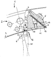
- a knife ring cutter 1 comprises a knife ring 2 which is fixedly arranged on an axis, not shown in detail here.
- the knife ring comprises knife-carrying elements 5 arranged in the area of the outer circumference 4.
- a knife-bearing element 5 each comprises a cutting knife 6, which is arranged on a knife web 7.
- the cutting knife 6 is arranged on a circumferential side surface 8 of the knife bar 7.
- the side surface 9 opposite this side surface 8, which in the circumferential direction is opposite the side surface 8 in the opposite direction is designed as a smooth surface.
- a wear plate 11 is arranged on the surface 10 of the knife bar 7 which is directed toward the axis (not shown here).
- the wear plate 11 has several tasks. It supports on the one hand the end region 12 of the blade 13 of the cutting knife, and on the other hand against wear on the knife web 7.
- the wear plate 11 in this embodiment is extended in the direction of the side face 9, so that it is above the knife web 7 in the direction of the neighboring knife-carrying Element 5 'protrudes.
- the extended wear plate 11 thus forms a smooth further projection 15, which adjoins the side surface 9, but in such a way that there is no smooth transition but an offset.
- the wear plate 11 and the knife bar 7 can be made from different materials, the wear plate 11 being made from a wear-resistant material.
- a chip exit slot 16 is in each case formed between two adjacent knife elements 5 and 5 'directly by the cutting knife 6' of the one knife-bearing element 5 'and the wear plate 11 or the projection 15 of the other adjacent knife-bearing element.
- the chip exit channel 17 into the housing 3, in which the knife ring is arranged, is formed by the cutting knife 6 'of the knife-bearing element 5' and the surface 19 of the knife-bearing element 5.
- the design of the chip exit channels 17 with their smooth side walls offers the advantage that the chip removal is not disturbed by outstanding elements and blockages and thus a backflow into the inside of the knife ring 2 are avoided.
- the projection 15 of the wear plate 11 is free of openings. It also has a straight end edge. In the present case, it is completely smooth and flat.
Abstract
Description
Die Erfindung betrifft einen Messerringzerspaner, im einzelnen mit den Merkmalen aus dem Oberbegriff des Anspruches 1.The invention relates to a knife ring chipper, in particular with the features from the preamble of
Bekannt sind Messerringzerspaner, bei denen ein Messerring auf einer Achse in einem Zerspanergehäuse feststehend angeordnet ist. Auf dieser horizontalen Achse ist des weiteren ein Rotor, beispielswise in Form eines Schleuderflügelrades drehbar gelagert. Der Messerring umfaßt ein kreisringförmiges Traggestell, an dessen Umfang eine Vielzahl von messertragenden Elementen derart angeordnet sind, daß diese einen Spannaustrittsspalt miteinander bilden. Jedes messertragende Element umfaßt mindestens einen Messersteg, an dem zur Realisierung unterschiedlicher Spanstärken jeweils ein Stockmesser und ein Schneidmesser an den in Umfangsrichtung einander gegenüberliegenden Seitenflächen angeordnet und befestigt sind. Die Anordnung erfolgt dabei derart, daß in Einbaulage die Schneidmesser und Stockmesser jeweils in Umfangsrichtung gleichgerichtet an den Messerstegen, d.h. in Umfangsrichtung immer an den in die gleiche Richtung weisenden Seiten angeordnet sind.Knife ring chippers are known in which a knife ring is arranged fixedly on an axis in a chipper housing. A rotor, for example in the form of a centrifugal impeller, is rotatably mounted on this horizontal axis. The knife ring comprises an annular support frame, on the circumference of which a large number of knife-bearing elements are arranged such that they form a clamping exit gap with one another. Each knife-carrying element comprises at least one knife bar, on which a stick knife and a cutting knife are arranged and fastened on the side surfaces opposite one another in the circumferential direction in order to achieve different chip strengths. The arrangement is such that in the installed position the cutting knives and stick knives each have the same circumferential direction on the knife bars, i.e. are always arranged in the circumferential direction on the sides pointing in the same direction.
Am Messersteg ist des weiteren an der zur horizontalen Achse hin in radialer Richtung weisenden Fläche eine Verschleißplatte angeordnet.A wear plate is also arranged on the knife web on the surface pointing in the radial direction toward the horizontal axis.
Ein solcher Messerringzerspaner ist aus DE 24 10 176 A1 bekanntgeworden. Dabei weist die Verschleißplatte auf der freien Fläche des messertragenden Elementes einen Vorsprung auf. Dieser Vorsprung ist mit Durchbrechungen versehen, beispielsweise mit Bohrungen (siehe dort Figur 2a) oder mit randoffenen Ausnehmungen (siehe dort Figur 2b). Diese Durchbrechungen sollen einen Luftstrom als Späneträgerluft durchtreten lassen, um die Abführung der Späne radial nach außen zu begünstigen.Such a knife ring chipper has become known from DE 24 10 176 A1. The wear plate has a projection on the free surface of the knife-bearing element. This projection is provided with openings, for example with bores (see FIG. 2a there) or with open-edged recesses (see FIG. 2b there). These breakthroughs are said to have an air flow as chip carrier air Allow to pass through to promote the removal of the chips radially outwards.
Dieser Messerringzerspaner hat sich trotz der genannten Trägerluftkanäle nicht bewährt. Es kommt hierbei immer wieder zu Stauungen im Spanabführungskanal.This knife ring chipper has not proven itself despite the carrier air channels mentioned. This always leads to congestion in the chip removal duct.
Der Erfindung liegt die Aufgabe zugrunde, einen Messerringzerspaner der eingangs genannten Art derart weiterzuentwickeln, daß die Spanabfuhr einwandfrei erfolgt.The invention has for its object to develop a knife ring chipper of the type mentioned in such a way that the chip removal takes place properly.
Diese Aufgabe wird durch die kennzeichnenden Merkmale gelöst. Die Erfinder haben erkannt, daß die Durchbrechungen an den Spänestauungen im Abfuhrkanal schuld sind. Statt die Späneabfuhr zu begünstigen, bewirken sie das Gegenteil, vermutlich durch Turbulenzen nach dem Spanaustrittsschlitz. Demgemäß haben die Erfinder den Vorsprung der Verschleißplatte völlig frei von Durchbrechungen gestaltet. Außerdem ist seine Endkante weitgehend geradlinig. Außerdem sollte die Oberfläche des Vorsprunges möglichst glatt und eben sein.This task is solved by the characteristic features. The inventors have recognized that the breakthroughs are due to the chip build-up in the discharge channel. Instead of promoting chip removal, they do the opposite, presumably due to turbulence after the chip exit slot. Accordingly, the inventors have made the wear plate protrusion completely free of perforations. In addition, its end edge is largely straight. In addition, the surface of the projection should be as smooth and flat as possible.
Die Figur verdeutlicht einen Ausschnitt aus einem Messerringzerspaner mit einer erfindungsgemäßen Ausführung eines messertragenden Elementes. Ein Messerringzerpanner 1 umfaßt einen Messerring 2, welcher auf einer, hier im einzelnen nicht dargestellten Achse fest angeordnet ist. Der Messerring umfaßt im Bereich des Außenumfanges 4 angeordnete messertragende Elemete 5. Ein messertragendes Element 5 umfaßt jeweils ein Schneidmesser 6, welches an einem Messersteg 7 angeordnet ist.The figure illustrates a section of a knife ring chipper with an inventive design of a knife-bearing element. A
Das Schneidmesser 6 ist dabei an einer in Umfangsrichtung weisenden Seitenfläche 8 des Messersteges 7 angeordnet. Die dieser Seitenfläche 8 gegenüberliegende Seitenfläche 9, welche in Umfangsrichtung gegenüber der Seitenfläche 8 in die entgegengesetzte Richtung weist, ist als glatte Fläche ausgeführt. In radialer Richtung ist an der zur hier nicht dargestellten Achse hingerichteten Fläche 10 des Messersteges 7 eine Verschleißplatte 11 angeordnet. Die Verschleißplatte 11 hat mehrere Aufgaben. Sie stützt zum einen den Endbereich 12 der Klinge 13 des Schneidmessers, zum andern vor Verschleiß am Messersteg 7. Des weiteren ist die Verschleißplatte 11 in dieser Ausführung in Richtung der Seitenfläche 9 verlängert ausgeführt, so daß diese über den Messersteg 7 in Richtung des benachbarten messertragenden Elementes 5' hinausragt. Die verlängerte Verschleißplatte 11 bildet somit einen glatten weiteren Vorsprung 15, welche sich an die Seitenfläche 9 anschließt, jedoch derart, daß kein gleichmäßiger Übergang erfolgt sondern ein Versatz.The cutting knife 6 is arranged on a
Die Verschleißplatte 11 und der Messersteg 7 können dabei aus unterschiedlichen Materialien hergestellt werden, wobei die Verschleißplatte 11 aus einem gegen Verschleiß widerstandsfähigen Material gefertigt ist.The
Ein Spanaustrittsschlitz 16 wird jeweils zwischen zwei benachbarten Messerelementen 5 und 5' unmittelbar von dem Schneidmesser 6' des ein messertragenden Elementes 5' und der Verschleißplatte 11 bzw. des Vorsprunges 15 des anderen benachbarten messertragenden Elementes gebildet. Der Spanaustrittskanal 17 ins Gehäuse 3, in welchem der Messerring angeordnet ist, wird von dem Schneidmesser 6' des messertragenden Elementes 5' und der Fläche 19 des messertragenden Elementes 5 gebildet.A
Innerhalb des Messerringes 2 auf der Achse 3 ist desweiteren ein Rotor 20, beispielsweise in Form eines Flügelrades ausgebildet, drehbar angeordnet, der die Hackschnitzel gegen den, den Rotor umfangsseitig umhüllenden Messerring 2 schleudert. Die Schneidmesser 6 und 6' der messertragenden Elemente dienen dabei zum Zerspanen der Hackschnitzel in dünne Späne. Nach dem Zerspanen durchdringen die Späne zwischen den messertragende Elementen, beispielsweise 5 und 5', den Spanaustrittskanal 17 und gelangen von dort in einen hier nicht dargesellten Späneabzugskanal, aus dem sie beispielsweise in das nach unten offene Gehäuse des Messerringzerspaners abgeführt werden.Furthermore, a
Die Gestaltung der Spanaustrittskanäle 17 mit deren glatten Seitenwänden bietet den Vorteil, daß die Spanabfuhr nicht durch herausragende Elemente gestört wird und Verstopfungen und damit ein Rückstau in das Innere des Messerringes 2 vermieden werden.The design of the chip exit channels 17 with their smooth side walls offers the advantage that the chip removal is not disturbed by outstanding elements and blockages and thus a backflow into the inside of the
Die Verwendung der Verschleißplatten 11 zur Bildung der Spanaustrittsschlitze 16 bietet den Vorteil, daß diese Platten bei starkem Verschleiß schnell ausgewechselt werden können.The use of the
Gemäß der Erfindung ist es ganz entscheidend, daß der Vorsprung 15 der Verschleißplatte 11 frei von Durchbrechungen ist. Außerdem weist er eine geradlinige Endkante auf. Im vorliegenden Falle ist er völlig glatt und eben gestaltet.According to the invention it is very important that the projection 15 of the
Claims (2)
gekennzeichnet durch die folgenden Merkmale:
characterized by the following features:
Applications Claiming Priority (2)
| Application Number | Priority Date | Filing Date | Title |
|---|---|---|---|
| DE4428615 | 1994-08-12 | ||
| DE4428615 | 1994-08-12 |
Publications (1)
| Publication Number | Publication Date |
|---|---|
| EP0705668A1 true EP0705668A1 (en) | 1996-04-10 |
Family
ID=6525558
Family Applications (1)
| Application Number | Title | Priority Date | Filing Date |
|---|---|---|---|
| EP95107833A Withdrawn EP0705668A1 (en) | 1994-08-12 | 1995-05-23 | Knife ring cutter |
Country Status (1)
| Country | Link |
|---|---|
| EP (1) | EP0705668A1 (en) |
Cited By (3)
| Publication number | Priority date | Publication date | Assignee | Title |
|---|---|---|---|---|
| EP0744257A2 (en) * | 1995-05-23 | 1996-11-27 | B. Maier Zerkleinerungstechnik GmbH | Chipping machine for chips |
| WO1999059784A2 (en) * | 1998-05-16 | 1999-11-25 | B. Maier Zerkleinerungstechnik Gmbh | Blade ring cutter |
| AT406132B (en) * | 1998-05-28 | 2000-02-25 | Boehler Miller Messer Und Saeg | ARRANGEMENT OF A DISPOSABLE COMB KNIFE IN A KNIFE ROLLER |
Citations (9)
| Publication number | Priority date | Publication date | Assignee | Title |
|---|---|---|---|---|
| DE1199477B (en) * | 1964-06-06 | 1965-08-26 | Condux Werk | Machine for cutting, especially wood |
| DE2318731A1 (en) * | 1973-04-13 | 1974-10-24 | Maier Kg Maschf B | DRUM-LIKE KNIFE BASKET WITH INTERCHANGEABLE KNIFE PACKAGES |
| DE2360297A1 (en) * | 1973-12-04 | 1975-06-05 | Paul A Dr Ing Kirsten | Quick-change blade mounting for wood chipper - has clamp for each blade unit, actuated by eccentrics |
| DE2410176A1 (en) | 1974-03-04 | 1975-09-18 | Paul A Dr Ing Kirsten | Offcut remover for rotary knife cutters - hassair blow holes in the cutting block fasteners |
| DE2628764A1 (en) * | 1976-06-26 | 1977-12-29 | Kloeckner Gmbh & Co Geb | KNIFE FASTENING IN KNIFE RING CHIPPERS FOR CHIPPING |
| DE3146861A1 (en) * | 1981-11-26 | 1983-06-01 | Hombak Maschinenfabrik Gmbh & Co Kg, 6550 Bad Kreuznach | Wear shoe for a cutter-ring chipping tool |
| US4972888A (en) * | 1989-11-14 | 1990-11-27 | Acrowood Corporation | Blade-carrying drum assembly for chip slicing machines |
| EP0481952A1 (en) * | 1990-10-17 | 1992-04-22 | BÖHLER YBBSTALWERKE G.m.b.H. | Replaceable wear part |
| DE9206975U1 (en) * | 1991-05-23 | 1992-09-17 | Globus S.R.L., Galliate, Novara, It |
-
1995
- 1995-05-23 EP EP95107833A patent/EP0705668A1/en not_active Withdrawn
Patent Citations (9)
| Publication number | Priority date | Publication date | Assignee | Title |
|---|---|---|---|---|
| DE1199477B (en) * | 1964-06-06 | 1965-08-26 | Condux Werk | Machine for cutting, especially wood |
| DE2318731A1 (en) * | 1973-04-13 | 1974-10-24 | Maier Kg Maschf B | DRUM-LIKE KNIFE BASKET WITH INTERCHANGEABLE KNIFE PACKAGES |
| DE2360297A1 (en) * | 1973-12-04 | 1975-06-05 | Paul A Dr Ing Kirsten | Quick-change blade mounting for wood chipper - has clamp for each blade unit, actuated by eccentrics |
| DE2410176A1 (en) | 1974-03-04 | 1975-09-18 | Paul A Dr Ing Kirsten | Offcut remover for rotary knife cutters - hassair blow holes in the cutting block fasteners |
| DE2628764A1 (en) * | 1976-06-26 | 1977-12-29 | Kloeckner Gmbh & Co Geb | KNIFE FASTENING IN KNIFE RING CHIPPERS FOR CHIPPING |
| DE3146861A1 (en) * | 1981-11-26 | 1983-06-01 | Hombak Maschinenfabrik Gmbh & Co Kg, 6550 Bad Kreuznach | Wear shoe for a cutter-ring chipping tool |
| US4972888A (en) * | 1989-11-14 | 1990-11-27 | Acrowood Corporation | Blade-carrying drum assembly for chip slicing machines |
| EP0481952A1 (en) * | 1990-10-17 | 1992-04-22 | BÖHLER YBBSTALWERKE G.m.b.H. | Replaceable wear part |
| DE9206975U1 (en) * | 1991-05-23 | 1992-09-17 | Globus S.R.L., Galliate, Novara, It |
Cited By (5)
| Publication number | Priority date | Publication date | Assignee | Title |
|---|---|---|---|---|
| EP0744257A2 (en) * | 1995-05-23 | 1996-11-27 | B. Maier Zerkleinerungstechnik GmbH | Chipping machine for chips |
| EP0744257A3 (en) * | 1995-05-23 | 1997-06-11 | Maier Zerkleinerungstech Gmbh | Chipping machine for chips |
| WO1999059784A2 (en) * | 1998-05-16 | 1999-11-25 | B. Maier Zerkleinerungstechnik Gmbh | Blade ring cutter |
| WO1999059784A3 (en) * | 1998-05-16 | 2000-04-06 | Maier Zerkleinerungstech Gmbh | Blade ring cutter |
| AT406132B (en) * | 1998-05-28 | 2000-02-25 | Boehler Miller Messer Und Saeg | ARRANGEMENT OF A DISPOSABLE COMB KNIFE IN A KNIFE ROLLER |
Similar Documents
| Publication | Publication Date | Title |
|---|---|---|
| DE10215833A1 (en) | Cutter body with flail, has lateral surface of flail bearing body divided into segments | |
| DE202009017951U1 (en) | pulper | |
| EP1679403A1 (en) | Pulper for comminuting and suspending papermaking material | |
| DE2405702C3 (en) | Pulper for producing a pumpable suspension from dry paper raw materials | |
| EP0744257B1 (en) | Chipping machine for chips | |
| EP0705668A1 (en) | Knife ring cutter | |
| WO2012084562A1 (en) | Pressure screen | |
| DE3925098C2 (en) | Device for shredding material, so-called turbo separator | |
| DE2640334C2 (en) | Forage harvester | |
| DE2938215A1 (en) | CRUSHING DEVICE, ESPECIALLY FOR WOOD | |
| EP0367255B1 (en) | Wood chipping machine | |
| EP0807500B1 (en) | Chipping machine for chips | |
| DE2221479A1 (en) | KNIFE ROLLER FOR CUTTING MACHINES | |
| DE202005010055U1 (en) | Paddle cutter for chopping device has cutting edge pointing in rotating direction, which stretches across width of paddle cutter, from outer edge up to fixing zone which has opening for fixing the cutter on rotating part of chopping device | |
| WO2002040166A2 (en) | Centrifugal mill comprising two chambers | |
| DE2618254A1 (en) | Wood and paper refuse cutting drum - has discs mounted along shaft, each with projecting cutter blades | |
| DE102009005929B4 (en) | Cutting unit, especially for a meat grinder | |
| EP1574615A1 (en) | Refiner and refiner filling for paper pulp | |
| EP3381563A1 (en) | Chipper rotor | |
| DE2457403A1 (en) | Device for production of wood chippings - has paddle feed wheel with same axial intermediate space as ring cutter | |
| DE2651569A1 (en) | Fruit or vegetable cutter and shredder - has set of V=shaped blades placed on edge and movable through slit blade wiper | |
| EP1394318A1 (en) | Pressure screen for screening a fibrous suspension | |
| DE2437202A1 (en) | Feed system for comminution devices - has chute and vertical feed channel with parallel feed dividing sheets | |
| EP0175313B1 (en) | Waste comminuter | |
| DE3743071A1 (en) | Refiner for paper stock |
Legal Events
| Date | Code | Title | Description |
|---|---|---|---|
| PUAI | Public reference made under article 153(3) epc to a published international application that has entered the european phase |
Free format text: ORIGINAL CODE: 0009012 |
|
| AK | Designated contracting states |
Kind code of ref document: A1 Designated state(s): BE DE FR IT |
|
| STAA | Information on the status of an ep patent application or granted ep patent |
Free format text: STATUS: THE APPLICATION IS DEEMED TO BE WITHDRAWN |
|
| 18D | Application deemed to be withdrawn |
Effective date: 19961011 |