EP0705564B1 - Verfahren zum Erzeugen einer Abbildung mit Hilfe einer Ultraschall-Abtastanordnung - Google Patents
Verfahren zum Erzeugen einer Abbildung mit Hilfe einer Ultraschall-Abtastanordnung Download PDFInfo
- Publication number
- EP0705564B1 EP0705564B1 EP95307083A EP95307083A EP0705564B1 EP 0705564 B1 EP0705564 B1 EP 0705564B1 EP 95307083 A EP95307083 A EP 95307083A EP 95307083 A EP95307083 A EP 95307083A EP 0705564 B1 EP0705564 B1 EP 0705564B1
- Authority
- EP
- European Patent Office
- Prior art keywords
- beams
- image field
- image
- beam direction
- scanning
- Prior art date
- Legal status (The legal status is an assumption and is not a legal conclusion. Google has not performed a legal analysis and makes no representation as to the accuracy of the status listed.)
- Expired - Lifetime
Links
Images


Classifications
-
- G—PHYSICS
- G01—MEASURING; TESTING
- G01S—RADIO DIRECTION-FINDING; RADIO NAVIGATION; DETERMINING DISTANCE OR VELOCITY BY USE OF RADIO WAVES; LOCATING OR PRESENCE-DETECTING BY USE OF THE REFLECTION OR RERADIATION OF RADIO WAVES; ANALOGOUS ARRANGEMENTS USING OTHER WAVES
- G01S7/00—Details of systems according to groups G01S13/00, G01S15/00, G01S17/00
- G01S7/52—Details of systems according to groups G01S13/00, G01S15/00, G01S17/00 of systems according to group G01S15/00
- G01S7/52017—Details of systems according to groups G01S13/00, G01S15/00, G01S17/00 of systems according to group G01S15/00 particularly adapted to short-range imaging
- G01S7/52085—Details related to the ultrasound signal acquisition, e.g. scan sequences
-
- G—PHYSICS
- G01—MEASURING; TESTING
- G01S—RADIO DIRECTION-FINDING; RADIO NAVIGATION; DETERMINING DISTANCE OR VELOCITY BY USE OF RADIO WAVES; LOCATING OR PRESENCE-DETECTING BY USE OF THE REFLECTION OR RERADIATION OF RADIO WAVES; ANALOGOUS ARRANGEMENTS USING OTHER WAVES
- G01S7/00—Details of systems according to groups G01S13/00, G01S15/00, G01S17/00
- G01S7/52—Details of systems according to groups G01S13/00, G01S15/00, G01S17/00 of systems according to group G01S15/00
- G01S7/52017—Details of systems according to groups G01S13/00, G01S15/00, G01S17/00 of systems according to group G01S15/00 particularly adapted to short-range imaging
- G01S7/52046—Techniques for image enhancement involving transmitter or receiver
- G01S7/52047—Techniques for image enhancement involving transmitter or receiver for elimination of side lobes or of grating lobes; for increasing resolving power
-
- G—PHYSICS
- G01—MEASURING; TESTING
- G01S—RADIO DIRECTION-FINDING; RADIO NAVIGATION; DETERMINING DISTANCE OR VELOCITY BY USE OF RADIO WAVES; LOCATING OR PRESENCE-DETECTING BY USE OF THE REFLECTION OR RERADIATION OF RADIO WAVES; ANALOGOUS ARRANGEMENTS USING OTHER WAVES
- G01S7/00—Details of systems according to groups G01S13/00, G01S15/00, G01S17/00
- G01S7/52—Details of systems according to groups G01S13/00, G01S15/00, G01S17/00 of systems according to group G01S15/00
- G01S7/52017—Details of systems according to groups G01S13/00, G01S15/00, G01S17/00 of systems according to group G01S15/00 particularly adapted to short-range imaging
- G01S7/52053—Display arrangements
- G01S7/52057—Cathode ray tube displays
- G01S7/5206—Two-dimensional coordinated display of distance and direction; B-scan display
- G01S7/52063—Sector scan display
-
- G—PHYSICS
- G01—MEASURING; TESTING
- G01S—RADIO DIRECTION-FINDING; RADIO NAVIGATION; DETERMINING DISTANCE OR VELOCITY BY USE OF RADIO WAVES; LOCATING OR PRESENCE-DETECTING BY USE OF THE REFLECTION OR RERADIATION OF RADIO WAVES; ANALOGOUS ARRANGEMENTS USING OTHER WAVES
- G01S15/00—Systems using the reflection or reradiation of acoustic waves, e.g. sonar systems
- G01S15/88—Sonar systems specially adapted for specific applications
- G01S15/89—Sonar systems specially adapted for specific applications for mapping or imaging
- G01S15/8906—Short-range imaging systems; Acoustic microscope systems using pulse-echo techniques
- G01S15/8909—Short-range imaging systems; Acoustic microscope systems using pulse-echo techniques using a static transducer configuration
- G01S15/8915—Short-range imaging systems; Acoustic microscope systems using pulse-echo techniques using a static transducer configuration using a transducer array
- G01S15/8918—Short-range imaging systems; Acoustic microscope systems using pulse-echo techniques using a static transducer configuration using a transducer array the array being linear
-
- G—PHYSICS
- G01—MEASURING; TESTING
- G01S—RADIO DIRECTION-FINDING; RADIO NAVIGATION; DETERMINING DISTANCE OR VELOCITY BY USE OF RADIO WAVES; LOCATING OR PRESENCE-DETECTING BY USE OF THE REFLECTION OR RERADIATION OF RADIO WAVES; ANALOGOUS ARRANGEMENTS USING OTHER WAVES
- G01S15/00—Systems using the reflection or reradiation of acoustic waves, e.g. sonar systems
- G01S15/88—Sonar systems specially adapted for specific applications
- G01S15/89—Sonar systems specially adapted for specific applications for mapping or imaging
- G01S15/8906—Short-range imaging systems; Acoustic microscope systems using pulse-echo techniques
- G01S15/8979—Combined Doppler and pulse-echo imaging systems
Definitions
- This invention relates to an echographic imaging method and an echographic imaging apparatus for scanning an image field with pulses of ultrasonic energy which are transmitted in a plurality of beam directions extending spatially adjacent to each other over said image field from one lateral extreme of said image field and through the center of said image field to an opposite lateral extreme, and for receiving echoes from the current beam direction with minimized multi-path reception and image artifacts.
- the invention finds an application in improvements of ultrasonic diagnostic imaging techniques, and in particular of ultrasonic image scanning techniques which reduce the effects of temporal scanning artifacts in an ultrasonic image.
- the cited Document relates to an ultrasound equipment, illustrated by FIG.5 of said Document, which comprises a set of ultrasound transducers disposed along the circumference of a supporting member. Each of said ultrasound transducers transmits a fan-shaped beam, which scans a fan-shaped field of the object and forms a fan-shaped view. So, each fan-shaped beam has a first and a second lateral extremes.
- the different transducers each scanning a fan-shaped field from said different angles, are energized sequentially one after the other, beginning with a central projection utilizing a first transducer, and then utilizing alternately the first left transducer, then the first right transducer, then the second left transducer and then the second right transducer in order to ensure that the first and last views are obtained close in time.
- the fan-shaped beams are energized alternately, in a diverging pattern starting from a unique central location of the first fan-shaped beam, and the fan-shaped views are formed from said fan-shaped beams.
- a reconstructed final image is formed from all said five fan-shaped views.
- the object to be imaged can show movements during the time of formation of the five fan-shaped views.
- the magnitude of the inconsistencies, due to the movements of said object between the first and last views, is reduced, because said first and last views are close in time.
- a final image that is constructed from said five images exhibits a reduced susceptibility to motion artifacts.
- Ultrasonic images can suffer from a number of image artifact problems, one of which is due to range ambiguities induced by multi-path reflections.
- Ultrasonic images are developed by transmitting ultrasonic pulses over a range of directions called beam directions which cover an image field of a subject being imaged, such as the interior of the human body. After each ultrasonic beam is transmitted echoes are received from along the beam direction over a predetermined depth of field. These transmission and reception sequences are repeated until beams have been scanned over and echoes gathered from along beam directions which cover the desired image field.
- the time of flight of ultrasonic pulses and echoes together with the beam directions the locations of specific echoes received from the image field are determined. After all of the echoes from the beams of the image field have been received and so arranged in an image format, the resultant ultrasonic image is displayed on a monitor.
- the time required to produce an ultrasonic image is determined by the number of beams comprising the image and the sum of the times required to transmit each beam and receive the resulting echoes.
- Each transmit-receive sequence is followed by another in a different beam direction until the entire image field has been scanned and echoes recorded.
- the time required to assemble the echo information needed to display a full image establishes the rate at which consecutive images can be displayed, the frame rate.
- High frame rates are desirable to eliminate any disturbing flicker or hesitation in the real time display of images.
- the transmitted image beams are often interlineated in time with narrow band Doppler pulse transmission and reception sequences for the simultaneous display of a structural image with flow information.
- the complete set of image and Doppler sequences can cause the time to assemble one display frame to increase substantially, and a commensurate significant decline in the frame rate of display.
- the transducers receiving echoes from one beam direction can also be receiving echoes resulting from the pulse transmission in another beam direction.
- the possibility of such cross contamination of the received signals is heightened whenever the pulse sequencing falls below the full round trip time of a pulse and its echoes.
- the inadvertent reception of echoes caused by other than the intended transmitted pulse is possible even when the full round trip time is observed. This is due to what is referred to as multi-path reception. Multi-path reception arises when a first pulse is reflected by structure so as to continue to travel through the image field, generating echoes and itself even returning to the transducer, during the reception period of a subsequent transmit-receive sequence.
- a sequence of spatially scanning an ultrasonic sector image field which provides a reduction in multi-path artifacts in the received echo signals.
- the scanning sequence is performed by symmetrically scanning beam directions alternately on respective sides of the sector.
- a diverging sequence begins by scanning the two central beam directions of the sector. The sequence continues by scanning outwardly from the two central beams in accurately divergent directions, alternating from one side of the sector to the other. The last two beams scanned are the two most lateral beam directions.
- a relatively long pulse repetition interval may be inserted between the transmit-receive sequences of the central beam directions, where consecutive beam scans are most closely adjacent. As the scanning sequence diverges from the center of the sector and consecutively transmitted beams become more widely separated in space, the PRI can be reduced to increase the frame rate.
- the scanning sequence first diverges from the center of the sector then converges, the sequence proceeding alternately outward from the sector center during one frame then back again during the next frame.
- an artifact can develop down the center of a divergently scanned image.
- the center line of the image is scanned as the first line scanned of each new image frame. This causes the center line to be significantly noise-free as compared to other divergently scanned lines, since an adjacent line has generally been scanned within two transmission-reception time periods. This unique characteristic of the center line can cause an artifact to appear down the center of the image in the form of a faint or dim central line.
- the central artifact caused by divergent scanning is overcome by scanning the image in a convergent scan pattern.
- convergent scanning begins on one lateral extreme of the image, then scans the line on the other lateral extreme, and continues scanning alternately inward from these two lateral extremes. This effectively relocates the central artifact of the divergently scanned image to the most lateral extreme of the image where it is not noticeable.
- a further refinement of this technique is to divergently scan the image beginning with a different starting point in each successive image frame.
- the starting point in each successive frame can rotate from one line to the next, or can be randomly chosen. This variation in the starting point will dissipate the effect of the artifact by continually relocating it to a different position each frame and allowing it to be reproduced in the same place no more than once in succession.
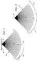
- the image sector 10 comprises n scan lines along which focused ultrasound pulses are transmitted and from which echoes are received by an ultrasonic transducer 30 located at or in the vicinity of the apex 20 of the sector.
- the transducer 30 in this example is a multi-element transducer by which an ultrasound beam can be electronically focused and steered as is known in the art on both transmit and receive.
- the sector area 10 which is covered by the successively transmitted beams is seen to be in the shape of a section of a circle and is drawn with a center line 12. The n transmitted beams are distributed on either side laterally of the illustrated center line 12.
- Successive beams are transmitted as shown by beams numbered 1, 2, 3, and so forth beginning at the left lateral side of the sector.
- a pulse is transmitted in each beam direction there is a reception period during which echoes are received by the transducer from along the beam direction.
- the receiver is turned off and the transducer's control system is readied for transmission in the next beam direction. Transmission and reception continues in this sequence and ends with the beam identified as n at the right lateral side of the sector.
- each successive beam direction is immediately adjacent to the previous beam direction.
- multi-path reflections are passing back and forth along a given beam direction they will most likely be overlapping the adjacent beam direction along which echoes are next to be received.
- multi-path reflections from the previous beam transmission will be received and artifacts created when the transducer is activated to begin receiving from along the adjacent beam direction.
- a waiting period is inserted following each transmit-receive sequence.
- the transmitter is inhibited for a waiting period which, together with the transmission and reception time, are referred to as the pulse repetition interval, or PRI.
- the pulse repetition interval or PRI.
- the multi-path reflections will become attenuated by passage through the subject.
- the next transmit receive sequence begins in the next beam direction.
- FIGURE 2 illustrates one known approach to reducing the problem of multi-path reflection artifacts
- N beam directions are scanned in the sequence of the illustrated beam numbering.
- the lateral beam direction 1 is scanned first.
- the second beam direction to be scanned is the beam direction 2 which is to the right of the center line of the sector 10.
- the third beam direction to be scanned is numbered 3, spatially adjacent to beam 1.
- the fourth beam direction scanned is labeled 4, spatially adjacent to beam 2.
- the sequence continues in this manner, alternating between the previously scanned beam directions of each half of the sector, and ending with the scanning of beam directions N-1 and N.
- Multi-path reflections along beam direction 1 should have little effect on echoes received immediately thereafter from along beam direction 2.
- the temporal disparity between the scanning of adjacent lines is uniformly established at two PRI's. Beam direction 3 is scanned two PRI's after beam direction 1, beam direction 5 is scanned two PRI's after beam direction 3, and so forth.
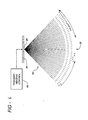
- FIGURE 3 the timing of a transducer array 30 is controlled by a transmit-receive controller 60.
- the scanning sequence begins by sequentially scanning the two beam directions 1 and 2 on either side of the center line 12 of the sector 10. After beam direction 2 on the right side of the sector has been scanned, the beam direction 3 to the left of beam direction 1 is scanned. This is followed by the scanning of beam direction 4 to the right of beam direction 2. It is seen that the scanning sequence proceeds laterally outward from the center of the sector and alternates back and forth from one side of the sector to the other.
- this scanning technique preserves a temporal uniformity in the scanning of spatially adjacent beam directions.
- Each beam direction is scanned two PRI intervals apart from its spatial neighbors uniformly across the entire image.
- the problem of multi-path reflection artifacts is markedly reduced by the two PRI intervals between spatially adjacent beam directions.
- Multi-path reflections have a two PRI period of time to dissipate before a spatially adjacent beam direction is scanned.
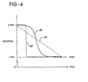
- This graph shows techniques for varying the PRI over the time interval that the full sector is scanned. Since beam directions 1 and 2 are spatially adjacent to each other, the dashed line 30 shows that a full waiting period of one PRI is inserted between the transmit-receive sequences of these two lines. During this one PRI waiting period multipath reflections in the vicinity of beam direction 1 are given a full PRI interval to dissipate before adjacent beam direction 2 is scanned. As the consecutively scanned beams move further and further apart spatially, this waiting period is reduced toward zero at a time when it is no longer needed. Dashed line 30 shows a smooth linear reduction in this PRI interval over time from one sequence to the next.
- FIGURE 4 shows, calculations and experience may show that the waiting periods are not needed after a relatively short period of time.
- This broken line shows the maintenance of a full PRI interval waiting period between the initial time consecutive sequences, and a sudden change to no additional waiting time when consecutively scanned beams exhibit sufficient spatial separation and no longer benefit from the additional PRI interval. It has been found, however, that a vertical band may appear in each half of the sector between those beam directions where the shift in PRI occurred.
- FIG. 4 Another alternative waiting period variation is shown by the curve 40 in FIGURE 4.
- This curve shows the maintenance of a waiting period of about a full PRI interval between beam scanning sequences in the vicinity of the center of the sector. Shortly thereafter, however, there is a smooth but rapid decline in the waiting period between consecutively scanned beam directions. The waiting period decline quickly reaches zero, after which there is no waiting period between consecutively scanned beams and a uniform one PRI interval is established between the scanning times of time consecutive beams, resulting in two PRI intervals between the scanning times of the remaining adjacent beams.
- This PRI variation technique will yield a beneficial balance between multipath artifact reduction and maintenance of a relatively high frame rate.
- a variation of the inventive scanning sequence is to scan outwardly from the center of the sector during one image frame, then inwardly from the lateral edges of the sector during the next successive frame.
- the sequence alternates back and forth between inward and outward scanning during successive image frames. While providing the benefits enumerated above for the preferred embodiment, this variation has the characteristic of a frame to frame variation in the temporal scanning of each beam direction. After the central beam directions 1 and 2 have been scanned at the beginning of the scanning period for the first frame, almost two frame intervals pass before they are scanned at the end of the second frame scanning period. These beam directions are then scanned immediately thereafter at the beginning of the third frame scanning period. Consequently, this varying sequence may not be as completely free of the effects of temporal scanning nonuniformity as the preferred embodiment.
- the divergent scanning sequence of FIGURE 3 can result in a slight vertical artifact at the center of the sector due to the start of the sequence at the center of the sector.
- the last beam direction scanned for a given image is one of the most lateral beam directions.
- the first beam direction scanned at the start of a new image is beam direction 1 at the center of the sector.
- Beam direction 1 is transmitted at a time when the preceding transmissions have been at the most lateral extremities of the previous image. Hence, a considerable amount of time has passed since any transmission occurred at the sector center, leaving the center significantly free of echo artifacts from previous transmissions.
- the echoes received from along beam direction 1 will thus be significantly free of artifacts and noise.
- Beam direction 1 was scanned at a time when almost a full image period has passed since a nearby disturbance occurred and will be significantly free of artifacts. Consequently the echoes from beam direction 1 can appear fainter than those of the surrounding beams, simply due to the exceedingly noise free environment from which they were received. The central line of the sector can therefore appear different from its neighbors, an "artifact" in the image.
- this temporal artifact at the image center can be eliminated by convergent scanning of the sector as illustrated in FIGURE 5.
- the scanning of the sector begins with beam direction 1 at one lateral extreme of the image.
- the second beam direction 2 scanned is at the other lateral extreme of the image.
- Alternate scanning continues from side to side as shown by the numbered beam directions, ending at the center of the image. This causes the center beams to be temporally related and substantially equally affected by surrounding remnant reverberations from previous transmissions, eliminating the faint appearance down the center of the image.
- the effective result of convergent scanning as compared with divergent scanning is to relocate the first beam scanned in a given frame, and hence the artifact, to the most lateral extremes of the image, where it is unnoticeable.
- transmissions without echo reception could be employed at either lateral side of the sector prior to the commencement of the beam transmissions from which echoes are to be received.
- FIGURE 6 illustrates the scanning sequence beginning five lines in from the right lateral side of the sector. From the perspective of this point of the sector, the scanning sequence is diverging, as lines 1, 2, 3, 4, 5, etc. sequentially diverge from beam directions 1 and 2. After beam 9 has scanned the right lateral side of the sector, beam 11 scans the left lateral side and subsequent odd numbered beams scan inward from the left side of the sector. From the perspective of the left side of the sector the scanning sequence is converging, and will end five lines to the left of the center line 12.
- the first beam direction is located in a different beam direction.
- the first beam direction could be rotationally changed, proceeding to the sixth or fourth line in from the right lateral side of the sector, it could be randomly chosen, or it can vary in some other manner from frame to frame.
- This first beam alteration technique has the effect of eliminating the faint first line artifact by continually relocating it and thereby uniformly blending it into the real time image sequence.
- the blending may be effected by the frame rate of the real time display, or successive frames can be averaged to eliminate the artifact.
- the inventive scanning sequence is also applicable to other scanning formats such as the rectangular format of a linear scan.
- the ultrasonic beams are transmitted in parallel directions from groups of transducer elements of a linear transducer array.
- the linear scan will proceed in the same manner as the sector scan, beginning with the two most lateral beams and proceeding alternately to scan beam directions on the inward side of the two initial beam directions and proceeding toward the center. Trapezoidal and other beam patterns are also possible.
Claims (4)
- Echografisches Bildgebungsverfahren zum Abtasten eines Bildfeldes (10) mit Impulsen mit Ultraschallenergie, die in einer Vielzahl von Strahlrichtungen gesendet werden, die sich räumlich nebeneinander über das genannte Bildfeld von einem seitlichen Rand des genannten Bildfeldes und durch die Mitte des genannten Bildfeldes zu einem gegenüberliegenden seitlichen Rand erstrecken, und zum Empfangen von Echos aus der aktuellen Strahlrichtung mit einem Minimum an Mehrwegeempfang und Bildartefakten, das folgende Schritte umfasst:Senden in einer ersten Strahlrichtung (1) und dann in einer zweiten Strahlrichtung (2), wobei die Richtungen im Wesentlichen jeweils an den genannten seitlichen Rändern des genannten Bildfeldes angeordnet sind; und anschließendSenden in einer dritten Strahlrichtung (3), die neben und seitlich nach innen in Bezug auf die genannte erste Strahlrichtung liegt, und dann in einer vierten Strahlrichtung (4), die neben und seitlich nach innen in Bezug auf die genannte zweite Strahlrichtung liegt; und dannFortsetzen der Abtastung des genannten Bildfeldes durch Senden in Strahlrichtungen, die gemäß eines konvergenten Abtastmusters abwechselnd auf den gegenüberliegenden Innenseiten der vorher gesendeten Strahlrichtungen liegen.
- Verfahren nach Anspruch 1, wobei die genannte erste (1) und die genannte dritte (3) Strahlrichtung auf einer Seite der Mitte des genannten Bildfeldes liegen und die genannte zweite (2) und die genannte vierte (4) Strahlrichtung auf der anderen Seite der genannten Mitte des genannten Bildfeldes liegen.
- Echografisches Ultraschallgerät zum Abtasten eines Bildfeldes (10) eines Objektes, das sich von der Mitte des genannten Feldes in im Wesentlichen entgegen gesetzten Richtungen zu seitlichen Rändern des genannten Feldes erstreckt, mit Ultraschallstrahlenbündeln, die nach einem Muster gesendet werden, bei dem die Strahlenbündel räumlich nebeneinander in dem genannten Bildfeld liegen, und zum Empfangen von Echos von dem aktuellen Strahlenbündel mit einem Minimum an Mehrwegeempfang und Bildartefakten, wobei das echographische Ultraschallgerät Mittel für folgende Aufgaben umfasst:Sequentielles Senden von ersten und zweiten Ultraschallstrahlenbündel (1, 2) auf den entsprechenden Seiten des genannten Bildfeldes; undSequentielles Senden von nachfolgenden Strahlenbündeln abwechselnd auf den beiden Seiten des genannten Bildfeldes, wobei die aufeinander folgenden Strahlenwege gemäß einem konvergierenden Muster an abnehmenden seitlichen Positionen in Bezug auf die Positionen des genannten ersten und des genannten zweiten Ultraschallstrahlenbündels liegen.
- Gerät nach Anspruch 3, das ferner Mittel umfasst, um die Zeitintervalle zwischen der Übertragung von zeitlich aufeinander folgenden Strahlen folgendermaßen zu verändern:von relativ kürzeren Intervallen zwischen Strahlenbündeln, die in der Nähe der seitlichen Ränder des genannten Bildfelds gesendet werden,zu relativ längeren Intervallen zwischen den Zeitpunkten der aufeinander folgenden Sendevorgänge von Strahlenbündeln, die mehr in der Mitte liegen.
Priority Applications (1)
| Application Number | Priority Date | Filing Date | Title |
|---|---|---|---|
| EP03100346A EP1327892A3 (de) | 1994-10-07 | 1995-10-06 | Verfahren zum Erzeugen einer Abbildung mit Hilfe einer Ultraschall-Abtastanordnung |
Applications Claiming Priority (4)
| Application Number | Priority Date | Filing Date | Title |
|---|---|---|---|
| US319757 | 1994-10-07 | ||
| US08/319,757 US5438994A (en) | 1994-10-07 | 1994-10-07 | Ultrasonic diagnostic image scanning |
| US08/489,668 US5617863A (en) | 1994-10-07 | 1995-06-12 | Ultrasonic diagnostic image scanning techniques |
| US489668 | 1995-06-12 |
Related Child Applications (1)
| Application Number | Title | Priority Date | Filing Date |
|---|---|---|---|
| EP03100346A Division EP1327892A3 (de) | 1994-10-07 | 1995-10-06 | Verfahren zum Erzeugen einer Abbildung mit Hilfe einer Ultraschall-Abtastanordnung |
Publications (3)
| Publication Number | Publication Date |
|---|---|
| EP0705564A2 EP0705564A2 (de) | 1996-04-10 |
| EP0705564A3 EP0705564A3 (de) | 1996-08-28 |
| EP0705564B1 true EP0705564B1 (de) | 2004-02-04 |
Family
ID=26982140
Family Applications (1)
| Application Number | Title | Priority Date | Filing Date |
|---|---|---|---|
| EP95307083A Expired - Lifetime EP0705564B1 (de) | 1994-10-07 | 1995-10-06 | Verfahren zum Erzeugen einer Abbildung mit Hilfe einer Ultraschall-Abtastanordnung |
Country Status (3)
| Country | Link |
|---|---|
| EP (1) | EP0705564B1 (de) |
| AT (1) | ATE258765T1 (de) |
| DE (1) | DE69532519T2 (de) |
Families Citing this family (2)
| Publication number | Priority date | Publication date | Assignee | Title |
|---|---|---|---|---|
| US6113545A (en) * | 1998-04-20 | 2000-09-05 | General Electric Company | Ultrasonic beamforming with improved signal-to-noise ratio using orthogonal complementary sets |
| DE102011001147A1 (de) | 2011-03-08 | 2012-09-13 | Sma Solar Technology Ag | Vormagnetisierte AC-Drossel mit Polwender |
Family Cites Families (4)
| Publication number | Priority date | Publication date | Assignee | Title |
|---|---|---|---|---|
| FR2542884B1 (fr) | 1983-03-18 | 1986-12-26 | Cgr Ultrasonic | Procede d'imagerie par ultrasons a partir d'un alignement d'elements transducteurs |
| US4581581A (en) * | 1983-06-30 | 1986-04-08 | General Electric Company | Method of projection reconstruction imaging with reduced sensitivity to motion-related artifacts |
| US4888694A (en) * | 1987-10-28 | 1989-12-19 | Quantum Medical Systems, Inc. | Ultrasound imaging system for relatively low-velocity blood flow at relatively high frame rates |
| US5123415A (en) * | 1990-07-19 | 1992-06-23 | Advanced Technology Laboratories, Inc. | Ultrasonic imaging by radial scan of trapezoidal sector |
-
1995
- 1995-10-06 EP EP95307083A patent/EP0705564B1/de not_active Expired - Lifetime
- 1995-10-06 AT AT95307083T patent/ATE258765T1/de not_active IP Right Cessation
- 1995-10-06 DE DE69532519T patent/DE69532519T2/de not_active Expired - Fee Related
Also Published As
| Publication number | Publication date |
|---|---|
| DE69532519T2 (de) | 2004-12-30 |
| EP0705564A3 (de) | 1996-08-28 |
| EP0705564A2 (de) | 1996-04-10 |
| DE69532519D1 (de) | 2004-03-11 |
| ATE258765T1 (de) | 2004-02-15 |
Similar Documents
| Publication | Publication Date | Title |
|---|---|---|
| US5617863A (en) | Ultrasonic diagnostic image scanning techniques | |
| EP1664840B1 (de) | Ultraschall-kompoundierung mit aussenden multipler simultaner strahlen | |
| US5379642A (en) | Method and apparatus for performing imaging | |
| EP0706777B1 (de) | Gleichzeitiges Ultraschallabbildungs- und Doplleranzeigesystem | |
| US5301674A (en) | Method and apparatus for focusing transmission and reception of ultrasonic beams | |
| US20210338205A1 (en) | System and Method for Shear Wave Elastography by Transmitting Ultrasound with Subgroups of Ultrasound Transducer Elements | |
| US6537217B1 (en) | Method and apparatus for improved spatial and temporal resolution in ultrasound imaging | |
| US9310475B2 (en) | Method and apparatus for transmitting multiple beams | |
| US6228031B1 (en) | High frame rate ultrasonic diagnostic imaging systems with motion artifact reduction | |
| US6679846B2 (en) | Diagnostic ultrasound imaging method and system with improved frame rate | |
| US5797846A (en) | Method to control frame rate in ultrasound imaging | |
| EP2019624B1 (de) | Synthetische ultraschallübertragungsfokussierung mit mehrzeiligem strahlformer | |
| US6193662B1 (en) | High frame rate pulse inversion harmonic ultrasonic diagnostic imaging system | |
| JP2005523792A (ja) | 組織とフローをメージングするための合成的に焦点化される超音波診断イメージング・システム | |
| JPH04317639A (ja) | 超音波診断装置 | |
| EP2102682A1 (de) | System und verfahren für mehrzeilige farbdoppler- und angio-ultraschallbildgebung | |
| EP0406909B1 (de) | Diagnose-Ultraschallgerät | |
| US6517489B1 (en) | Method and apparatus for forming medical ultrasound images | |
| EP0705564B1 (de) | Verfahren zum Erzeugen einer Abbildung mit Hilfe einer Ultraschall-Abtastanordnung | |
| Arenson et al. | Real-time two-dimensional blood flow imaging using a Doppler ultrasound array | |
| JP2833155B2 (ja) | ドプラ断層超音波診断装置 | |
| KR19980067408A (ko) | 초음파 칼라 도플러 영상시스템을 위한 주사선 내삽(Scanline Interleave)방법 | |
| WO2009010918A2 (en) | System and method for coincident b-mode and doppler imaging using coded excitation | |
| WO2005034758A1 (ja) | 超音波診断装置 | |
| JPH04292159A (ja) | 超音波診断装置 |
Legal Events
| Date | Code | Title | Description |
|---|---|---|---|
| PUAI | Public reference made under article 153(3) epc to a published international application that has entered the european phase |
Free format text: ORIGINAL CODE: 0009012 |
|
| AK | Designated contracting states |
Kind code of ref document: A2 Designated state(s): AT BE CH DE DK ES FR GB GR IE IT LI LU MC NL PT SE |
|
| PUAL | Search report despatched |
Free format text: ORIGINAL CODE: 0009013 |
|
| AK | Designated contracting states |
Kind code of ref document: A3 Designated state(s): AT BE CH DE DK ES FR GB GR IE IT LI LU MC NL PT SE |
|
| 17P | Request for examination filed |
Effective date: 19970203 |
|
| 17Q | First examination report despatched |
Effective date: 19990201 |
|
| GRAH | Despatch of communication of intention to grant a patent |
Free format text: ORIGINAL CODE: EPIDOS IGRA |
|
| GRAS | Grant fee paid |
Free format text: ORIGINAL CODE: EPIDOSNIGR3 |
|
| GRAA | (expected) grant |
Free format text: ORIGINAL CODE: 0009210 |
|
| AK | Designated contracting states |
Kind code of ref document: B1 Designated state(s): AT BE CH DE DK ES FR GB GR IE IT LI LU MC NL PT SE |
|
| PG25 | Lapsed in a contracting state [announced via postgrant information from national office to epo] |
Ref country code: NL Free format text: LAPSE BECAUSE OF FAILURE TO SUBMIT A TRANSLATION OF THE DESCRIPTION OR TO PAY THE FEE WITHIN THE PRESCRIBED TIME-LIMIT Effective date: 20040204 Ref country code: LI Free format text: LAPSE BECAUSE OF FAILURE TO SUBMIT A TRANSLATION OF THE DESCRIPTION OR TO PAY THE FEE WITHIN THE PRESCRIBED TIME-LIMIT Effective date: 20040204 Ref country code: IT Free format text: LAPSE BECAUSE OF FAILURE TO SUBMIT A TRANSLATION OF THE DESCRIPTION OR TO PAY THE FEE WITHIN THE PRE;WARNING: LAPSES OF ITALIAN PATENTS WITH EFFECTIVE DATE BEFORE 2007 MAY HAVE OCCURRED AT ANY TIME BEFORE 2007. THE CORRECT EFFECTIVE DATE MAY BE DIFFERENT FROM THE ONE RECORDED.SCRIBED TIME-LIMIT Effective date: 20040204 Ref country code: ES Free format text: LAPSE BECAUSE OF FAILURE TO SUBMIT A TRANSLATION OF THE DESCRIPTION OR TO PAY THE FEE WITHIN THE PRESCRIBED TIME-LIMIT Effective date: 20040204 Ref country code: CH Free format text: LAPSE BECAUSE OF FAILURE TO SUBMIT A TRANSLATION OF THE DESCRIPTION OR TO PAY THE FEE WITHIN THE PRESCRIBED TIME-LIMIT Effective date: 20040204 Ref country code: BE Free format text: LAPSE BECAUSE OF FAILURE TO SUBMIT A TRANSLATION OF THE DESCRIPTION OR TO PAY THE FEE WITHIN THE PRESCRIBED TIME-LIMIT Effective date: 20040204 Ref country code: AT Free format text: LAPSE BECAUSE OF FAILURE TO SUBMIT A TRANSLATION OF THE DESCRIPTION OR TO PAY THE FEE WITHIN THE PRESCRIBED TIME-LIMIT Effective date: 20040204 |
|
| REG | Reference to a national code |
Ref country code: GB Ref legal event code: FG4D |
|
| REG | Reference to a national code |
Ref country code: CH Ref legal event code: EP |
|
| REG | Reference to a national code |
Ref country code: IE Ref legal event code: FG4D |
|
| REF | Corresponds to: |
Ref document number: 69532519 Country of ref document: DE Date of ref document: 20040311 Kind code of ref document: P |
|
| PG25 | Lapsed in a contracting state [announced via postgrant information from national office to epo] |
Ref country code: SE Free format text: LAPSE BECAUSE OF FAILURE TO SUBMIT A TRANSLATION OF THE DESCRIPTION OR TO PAY THE FEE WITHIN THE PRESCRIBED TIME-LIMIT Effective date: 20040504 Ref country code: GR Free format text: LAPSE BECAUSE OF FAILURE TO SUBMIT A TRANSLATION OF THE DESCRIPTION OR TO PAY THE FEE WITHIN THE PRESCRIBED TIME-LIMIT Effective date: 20040504 Ref country code: DK Free format text: LAPSE BECAUSE OF FAILURE TO SUBMIT A TRANSLATION OF THE DESCRIPTION OR TO PAY THE FEE WITHIN THE PRESCRIBED TIME-LIMIT Effective date: 20040504 |
|
| NLV1 | Nl: lapsed or annulled due to failure to fulfill the requirements of art. 29p and 29m of the patents act | ||
| REG | Reference to a national code |
Ref country code: CH Ref legal event code: PL |
|
| PG25 | Lapsed in a contracting state [announced via postgrant information from national office to epo] |
Ref country code: LU Free format text: LAPSE BECAUSE OF NON-PAYMENT OF DUE FEES Effective date: 20041006 Ref country code: IE Free format text: LAPSE BECAUSE OF NON-PAYMENT OF DUE FEES Effective date: 20041006 Ref country code: GB Free format text: LAPSE BECAUSE OF NON-PAYMENT OF DUE FEES Effective date: 20041006 |
|
| PGFP | Annual fee paid to national office [announced via postgrant information from national office to epo] |
Ref country code: FR Payment date: 20041027 Year of fee payment: 10 |
|
| ET | Fr: translation filed | ||
| PG25 | Lapsed in a contracting state [announced via postgrant information from national office to epo] |
Ref country code: MC Free format text: LAPSE BECAUSE OF NON-PAYMENT OF DUE FEES Effective date: 20041031 |
|
| PLBE | No opposition filed within time limit |
Free format text: ORIGINAL CODE: 0009261 |
|
| STAA | Information on the status of an ep patent application or granted ep patent |
Free format text: STATUS: NO OPPOSITION FILED WITHIN TIME LIMIT |
|
| 26N | No opposition filed |
Effective date: 20041105 |
|
| PG25 | Lapsed in a contracting state [announced via postgrant information from national office to epo] |
Ref country code: DE Free format text: LAPSE BECAUSE OF NON-PAYMENT OF DUE FEES Effective date: 20050503 |
|
| GBPC | Gb: european patent ceased through non-payment of renewal fee |
Effective date: 20041006 |
|
| REG | Reference to a national code |
Ref country code: IE Ref legal event code: MM4A |
|
| PG25 | Lapsed in a contracting state [announced via postgrant information from national office to epo] |
Ref country code: FR Free format text: LAPSE BECAUSE OF NON-PAYMENT OF DUE FEES Effective date: 20060630 |
|
| REG | Reference to a national code |
Ref country code: FR Ref legal event code: ST Effective date: 20060630 |
|
| PG25 | Lapsed in a contracting state [announced via postgrant information from national office to epo] |
Ref country code: PT Free format text: LAPSE BECAUSE OF NON-PAYMENT OF DUE FEES Effective date: 20040704 |