EP0705560A1 - Elastic, collecting lip for a floor cleaning machine - Google Patents
Elastic, collecting lip for a floor cleaning machine Download PDFInfo
- Publication number
- EP0705560A1 EP0705560A1 EP95115400A EP95115400A EP0705560A1 EP 0705560 A1 EP0705560 A1 EP 0705560A1 EP 95115400 A EP95115400 A EP 95115400A EP 95115400 A EP95115400 A EP 95115400A EP 0705560 A1 EP0705560 A1 EP 0705560A1
- Authority
- EP
- European Patent Office
- Prior art keywords
- pan
- floor
- edge
- machine
- flexibility
- Prior art date
- Legal status (The legal status is an assumption and is not a legal conclusion. Google has not performed a legal analysis and makes no representation as to the accuracy of the status listed.)
- Ceased
Links
- 238000004140 cleaning Methods 0.000 title claims abstract description 16
- 239000000463 material Substances 0.000 claims abstract description 11
- 239000007787 solid Substances 0.000 description 3
- 238000005452 bending Methods 0.000 description 2
- 238000001035 drying Methods 0.000 description 2
- 239000007788 liquid Substances 0.000 description 2
- 238000012423 maintenance Methods 0.000 description 2
- 238000010408 sweeping Methods 0.000 description 2
- 230000008878 coupling Effects 0.000 description 1
- 238000010168 coupling process Methods 0.000 description 1
- 238000005859 coupling reaction Methods 0.000 description 1
- 230000003247 decreasing effect Effects 0.000 description 1
- 230000001788 irregular Effects 0.000 description 1
- 230000008439 repair process Effects 0.000 description 1
- 238000005507 spraying Methods 0.000 description 1
- 238000005406 washing Methods 0.000 description 1
Images
Classifications
-
- A—HUMAN NECESSITIES
- A47—FURNITURE; DOMESTIC ARTICLES OR APPLIANCES; COFFEE MILLS; SPICE MILLS; SUCTION CLEANERS IN GENERAL
- A47L—DOMESTIC WASHING OR CLEANING; SUCTION CLEANERS IN GENERAL
- A47L11/00—Machines for cleaning floors, carpets, furniture, walls, or wall coverings
- A47L11/40—Parts or details of machines not provided for in groups A47L11/02 - A47L11/38, or not restricted to one of these groups, e.g. handles, arrangements of switches, skirts, buffers, levers
- A47L11/4036—Parts or details of the surface treating tools
- A47L11/4038—Disk shaped surface treating tools
-
- A—HUMAN NECESSITIES
- A47—FURNITURE; DOMESTIC ARTICLES OR APPLIANCES; COFFEE MILLS; SPICE MILLS; SUCTION CLEANERS IN GENERAL
- A47L—DOMESTIC WASHING OR CLEANING; SUCTION CLEANERS IN GENERAL
- A47L11/00—Machines for cleaning floors, carpets, furniture, walls, or wall coverings
- A47L11/40—Parts or details of machines not provided for in groups A47L11/02 - A47L11/38, or not restricted to one of these groups, e.g. handles, arrangements of switches, skirts, buffers, levers
- A47L11/4036—Parts or details of the surface treating tools
- A47L11/4041—Roll shaped surface treating tools
-
- A—HUMAN NECESSITIES
- A47—FURNITURE; DOMESTIC ARTICLES OR APPLIANCES; COFFEE MILLS; SPICE MILLS; SUCTION CLEANERS IN GENERAL
- A47L—DOMESTIC WASHING OR CLEANING; SUCTION CLEANERS IN GENERAL
- A47L11/00—Machines for cleaning floors, carpets, furniture, walls, or wall coverings
- A47L11/40—Parts or details of machines not provided for in groups A47L11/02 - A47L11/38, or not restricted to one of these groups, e.g. handles, arrangements of switches, skirts, buffers, levers
- A47L11/4061—Steering means; Means for avoiding obstacles; Details related to the place where the driver is accommodated
Definitions
- the present invention concerns floor-cleaning machines.
- roller brush rotates in correspondence with the floor, in the direction of motion of the machine.
- the machines provided with roller brushes present some drawbacks: it is not possible to clean and wash the floor in correspondence with the skirting-board and with the furniture, since the supports of the rollers hold them at a certain distance from the edge of the machine; on the other hand, the machines with brush wheels ensure more uniform cleaning, since almost all the bristles of the brush wheels pass over the same space on the floor.
- said machines can be provided only with a front sliding pan, inclined in stable position, so that if they find an obstacle in their way they don't get stuck, or otherwise the lower edge of the collecting pan must always be raised to prevent it from getting stuck and therefore from hindering the advance of the floor-cleaning machine.
- the pans used at present are rectangular and their edge, which slides on the uneven floor, gets stuck on protuberances and cracks.
- the machine hereinafter called “floor-sweeping and cleaning machine” is generally provided with a reservoir for the cleansing liquid, with a device for spraying and drying said liquid, with one or more brush wheels positioned side by side and/or with a roller and with a front or rear compartment for collecting dirt.
- the rotation of the brushes or of the roller removes solid dirt from the floor and conveys it first before the machine and then in the space between the two brushes. This movement pushes solid dirt in the collecting compartment.
- the invention described in this patent makes it possible to clean any kind of floor and to avoid all the above-mentioned drawbacks, since said pan slides on the floor and conveys all the dirt towards the compartment.
- a flexible pan is positioned behind the roller or brush; said pan slides on the floor and conveys the dirt removed by the brush or by the roller into the collecting compartment.
- Said pan is unstable, that is, the edge adhering to the floor is positioned before the edge which joins the pan and the machine.
- the invention described in this patent makes it possible to clean both smooth and uneven floors, owing to the presence of the pan which, by adhering to the floor, collects all the dirt removed by the brush and conveys it to the collecting compartment. When the pan gets stuck on the irregular surface of the floor, it releases itself and starts functioning again immediately afterwards.
- the pan is carried out with such a shape and/or material that its lower edge always adheres to the floor; when it meets irregularities, protuberances or cracks, the edge of the pan is blocked by the obstacle, but as the machine advances it bends thanks to its elastic properties and then goes beyond the obstacle and adheres to the floor again.
- This new "floor-sweeping and cleaning machine” provided with said new pan makes it possible to remove dirt completely from any kind of floor.
- the pan can be carried out in various shapes and materials.
- the pan is capable of releasing itself from the obstacle thanks to its flexibility.
- its elasticity in the section between the sliding edge and the edge in contact with the machine can vary, in particular, elasticity increases towards the sliding edge.
- Said gradual elasticity can be obtained, for example, by means of:
- the new pan is carried out in a semitriangular shape, which follows the profiles of two brushes with vertical rotation axis.
- the long side of the pan is fixed to the machine, while the other two sides are circle arc-shaped and join in a slightly rounded end, said end being positioned between the two rotary brushes.
- this new semitriangular pan does not get stuck like normal pans with straight sides; in fact, owing to its pointed shape, it can bend and then straighten again.
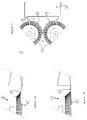
- Figure 1 is a schematic plan view of a floor-cleaning machine (A) provided with two brushes (B) with vertical axis, with a small basket (C) for collecting dirt and with a pan (D) which collects the dirt raised by the brushes (B) and conveys it into the collecting compartment.
- A floor-cleaning machine
- B two brushes
- C small basket
- D pan
- the pan (D) has semitriangular shape with the two sides (E) and (F) following the profile of the brushes (B) and being therefore curved; the two sides (E) and (F) join forming a point (H) which is particularly elastic and can easily bend if it gets stuck into cracks, fissures, etc.
- Figure 2a shows the pan (D) stuck on a crack (G); the pan (D) bends but does not break, being particularly elastic; the machine (A) is pushed forwards and the pan (D) releases itself and returns to its original position, without breaking (figure 2b).
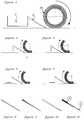
- Figure 3 shows a schematic section of the "floor-sweeping-and-cleaning" machine, in which it is possible to see the roller (B1) with rotation on horizontal axis, the sliding pan (D) for collecting dirt and the compartment (C).
- Figures from 4 to 7 shows the operation of the new pan (D) when it meets an obstacle (G), which in this case is a crack.
- Figures from 8 to 11 show several examples of implementation of the pan with variable elasticity: through triangular section (figure 8), material with different densities (figure 9), section with scalar thicknesses (figure 10), coupling of a substantially rigid material (R) with a substantially flexible end (L) (figure 11).
Landscapes
- Nozzles For Electric Vacuum Cleaners (AREA)
- Brushes (AREA)
Abstract
Description
- The present invention concerns floor-cleaning machines.
- At present several kinds of machines are used for the removal of dirt and for washing and drying floors, which are provided either with a roller rotating on an horizontal axis, or with rotary brushes with vertical axis.
- In the known kinds of machines the roller brush rotates in correspondence with the floor, in the direction of motion of the machine.
- In the known machines provided with circular brush wheels, which rotate on an almost vertical or slightly inclined axis, during the rotary movement the internal part of the disc advances in the direction of motion of the machine, so that dirt passes first before and then at the side of the machine.
- The machines provided with roller brushes present some drawbacks: it is not possible to clean and wash the floor in correspondence with the skirting-board and with the furniture, since the supports of the rollers hold them at a certain distance from the edge of the machine; on the other hand, the machines with brush wheels ensure more uniform cleaning, since almost all the bristles of the brush wheels pass over the same space on the floor.
- Since the rotation of brushes and disc exceeds the advance speed of the floor-cleaning machine, during the normal advance of the machine the same portion of floor is washed more than once by the brushes.
- It is desirable to implement a machine suitable for cleaning any kind of floor and capable of proceeding in both directions.
- In order to be able to work without problems when cleaning tiled floors or, however, floors with grooves or cracks, said machines can be provided only with a front sliding pan, inclined in stable position, so that if they find an obstacle in their way they don't get stuck, or otherwise the lower edge of the collecting pan must always be raised to prevent it from getting stuck and therefore from hindering the advance of the floor-cleaning machine. The pans used at present are rectangular and their edge, which slides on the uneven floor, gets stuck on protuberances and cracks.
- If the pan edge gets stuck on a crack, the machine suddenly stops and the pan bends and often breaks.
- In order to eliminate the above-mentioned drawbacks, a new kind of floor-cleaning machine has been studied and implemented, which is provided with a pan to collect solid dirt, wash and dry the floor on the spots which are most difficult to clean.
- The machine, hereinafter called "floor-sweeping and cleaning machine", is generally provided with a reservoir for the cleansing liquid, with a device for spraying and drying said liquid, with one or more brush wheels positioned side by side and/or with a roller and with a front or rear compartment for collecting dirt.
- The rotation of the brushes or of the roller removes solid dirt from the floor and conveys it first before the machine and then in the space between the two brushes. This movement pushes solid dirt in the collecting compartment.
- Owing to the new kind of pan, the invention described in this patent makes it possible to clean any kind of floor and to avoid all the above-mentioned drawbacks, since said pan slides on the floor and conveys all the dirt towards the compartment.
- To collect dirt, a flexible pan is positioned behind the roller or brush; said pan slides on the floor and conveys the dirt removed by the brush or by the roller into the collecting compartment.
- Said pan is unstable, that is, the edge adhering to the floor is positioned before the edge which joins the pan and the machine.
- The invention described in this patent makes it possible to clean both smooth and uneven floors, owing to the presence of the pan which, by adhering to the floor, collects all the dirt removed by the brush and conveys it to the collecting compartment. When the pan gets stuck on the irregular surface of the floor, it releases itself and starts functioning again immediately afterwards.
- The pan is carried out with such a shape and/or material that its lower edge always adheres to the floor; when it meets irregularities, protuberances or cracks, the edge of the pan is blocked by the obstacle, but as the machine advances it bends thanks to its elastic properties and then goes beyond the obstacle and adheres to the floor again.
- This new "floor-sweeping and cleaning machine" provided with said new pan makes it possible to remove dirt completely from any kind of floor.
- To serve the purpose effectively, the pan can be carried out in various shapes and materials.
- In any case, however, the pan is capable of releasing itself from the obstacle thanks to its flexibility.
- The new pan functions according to the following principles:
- yield of the pan to the bending and compressive stress, in presence of the obstacle;
- the yield is only upwards, since under the pan there is the floor and the obstacle is in front of it.
- In order to facilitate the bending of the pan, its elasticity in the section between the sliding edge and the edge in contact with the machine can vary, in particular, elasticity increases towards the sliding edge.
- Said gradual elasticity can be obtained, for example, by means of:
- different materials with different elastic characteristics;
- triangular section;
- section with scalar thicknesses;
- several superimposed layers of homogeneous and non-homogeneous materials;
- non-homogeneous materials with decreasing stiffness from the sliding edge towards the edge which joins the pan and the machine.
- If the machine is provided with brushes, the new pan is carried out in a semitriangular shape, which follows the profiles of two brushes with vertical rotation axis.
- The long side of the pan is fixed to the machine, while the other two sides are circle arc-shaped and join in a slightly rounded end, said end being positioned between the two rotary brushes.
- When there are cracks on the floor, this new semitriangular pan does not get stuck like normal pans with straight sides; in fact, owing to its pointed shape, it can bend and then straighten again.
- Maintenance operations, replacements and work stoppages are thus eliminated.
- The following is just an example among many of the practical embodiments of the invention in question, illustrated in the attached drawings.
- Figure 1 is a schematic plan view of a floor-cleaning machine (A) provided with two brushes (B) with vertical axis, with a small basket (C) for collecting dirt and with a pan (D) which collects the dirt raised by the brushes (B) and conveys it into the collecting compartment.
- The pan (D) has semitriangular shape with the two sides (E) and (F) following the profile of the brushes (B) and being therefore curved; the two sides (E) and (F) join forming a point (H) which is particularly elastic and can easily bend if it gets stuck into cracks, fissures, etc.
- Figure 2a shows the pan (D) stuck on a crack (G); the pan (D) bends but does not break, being particularly elastic; the machine (A) is pushed forwards and the pan (D) releases itself and returns to its original position, without breaking (figure 2b).
- In this way the pan itself lasts longer and does not require maintenance, repairs or work stoppages.
- Figure 3 shows a schematic section of the "floor-sweeping-and-cleaning" machine, in which it is possible to see the roller (B1) with rotation on horizontal axis, the sliding pan (D) for collecting dirt and the compartment (C).
- Figures from 4 to 7 shows the operation of the new pan (D) when it meets an obstacle (G), which in this case is a crack.
- Figures from 8 to 11 show several examples of implementation of the pan with variable elasticity: through triangular section (figure 8), material with different densities (figure 9), section with scalar thicknesses (figure 10), coupling of a substantially rigid material (R) with a substantially flexible end (L) (figure 11).
- The above are the basic outlines of the invention, on the basis of which the technician will be able to provide for implementation; therefore, any change which may be necessary upon implementation is to be regarded as completely protected by the present invention.
- With reference to the above description and the attached drawings, the following claims are put forth.
Claims (11)
- Pan for floor-cleaning machines, characterized in that it is sliding and arranged with the edge in contact with the floor facing the forward direction of the machine, said pan being positioned on the brush and/or roller side, so that removed dirt can be pushed towards the pan itself.
- Pan for floor-cleaning machines according to claim 1, characterized in that it is flexible, bends upwards when it meets an obstacle and then returns to its original position after going beyond the obstacle.
- Pan according to claims 1 and 2, characterized in that its flexibility increases along the section going from the edge in contact with the machine to the edge in contact with the floor, wherein said greater flexibility of the edge in contact with the floor favours the releasing of said pan from the obstacles.
- Pan according to claims 1, 2 and 3, characterized in that gradual flexibility is obtained through a continous variation of its thickness.
- Pan according to claims 1, 2 and 3, characterized in that gradual flexibility is obtained through a variation of the density of the material of which it is made.
- Pan according to claims 1, 2 and 3, characterized in that gradual flexibility is obtained through more than one layer of superimposed materials, with different lengths.
- Pan according to claims 1, 2 and 3, characterized in that gradual flexibility is obtained through the combination of two or more materials having different flexibility.
- Pan according to claims 1, 2 and 3, characterized in that gradual flexibility is obtained through a substantially triangular shape or section.
- Pan according to claims 1, 2 and 3, characterized in that its shape is substantially triangular, wherein the long side is fixed to the machine and the other two sides are curved like the edge of the brushes and the vertex is in forward position, between the two brushes.
- Pan according to claim 9, characterized in that its advancing side is point-shaped.
- Floor-cleaning machine, characterized in that it is provided with one or more collecting pans, according to all the previous claims.
Applications Claiming Priority (4)
| Application Number | Priority Date | Filing Date | Title |
|---|---|---|---|
| ITPD940104 IT234558Y1 (en) | 1994-10-05 | 1994-10-05 | PALETTE FOR MACHINE FOR CLEANING PSEUDO-TRIANGULAR FLOORS |
| ITPD940104U | 1994-10-05 | ||
| ITPD950035 | 1995-02-10 | ||
| IT95PD000035A IT1282190B1 (en) | 1995-02-10 | 1995-02-10 | Unstable variable elasticity sliding collector blade for floor cleaning machines |
Publications (1)
| Publication Number | Publication Date |
|---|---|
| EP0705560A1 true EP0705560A1 (en) | 1996-04-10 |
Family
ID=26331814
Family Applications (1)
| Application Number | Title | Priority Date | Filing Date |
|---|---|---|---|
| EP95115400A Ceased EP0705560A1 (en) | 1994-10-05 | 1995-09-29 | Elastic, collecting lip for a floor cleaning machine |
Country Status (4)
| Country | Link |
|---|---|
| US (1) | US5806123A (en) |
| EP (1) | EP0705560A1 (en) |
| CN (1) | CN1139542A (en) |
| BR (1) | BR9504774A (en) |
Cited By (3)
| Publication number | Priority date | Publication date | Assignee | Title |
|---|---|---|---|---|
| EP1179314A1 (en) * | 2000-08-12 | 2002-02-13 | Werner Kress | Sweeper with rotating cylindrical brush |
| JP2012228619A (en) * | 2010-10-25 | 2012-11-22 | Samsung Electronics Co Ltd | Robot vacuum cleaner |
| DE10242257C5 (en) * | 2001-09-14 | 2017-05-11 | Vorwerk & Co. Interholding Gmbh | Automatically movable floor dust collecting device, and combination of such a collecting device and a base station |
Families Citing this family (6)
| Publication number | Priority date | Publication date | Assignee | Title |
|---|---|---|---|---|
| DE19617986B4 (en) * | 1996-05-04 | 2004-02-26 | Ing. Haaga Werkzeugbau Kg | sweeper |
| US6698055B2 (en) * | 1999-12-10 | 2004-03-02 | Ing. Haaga Werkzeugbau Kg | Sweeping machine and sweeping lip |
| CN100393268C (en) * | 2003-09-20 | 2008-06-11 | 王可力 | Chassis of hand pushing floor sweeping machine |
| ES2270218T3 (en) * | 2004-05-07 | 2007-04-01 | Johnsondiversey, Inc. | CLEANING SYSTEM FOR SOIL TREATMENT. |
| EP2689701B1 (en) * | 2012-07-25 | 2018-12-19 | Samsung Electronics Co., Ltd. | Autonomous cleaning device |
| CN111248816B (en) * | 2020-01-21 | 2021-10-19 | 常熟理工学院 | Indoor comprehensive cleaning robot and its control method |
Citations (4)
| Publication number | Priority date | Publication date | Assignee | Title |
|---|---|---|---|---|
| DE1409783U (en) * | ||||
| US2740984A (en) * | 1956-04-10 | Dust removal system for surface treating machines | ||
| US5045118A (en) * | 1990-05-04 | 1991-09-03 | Tennant Company | Method of removing debris and dust from a carpet |
| EP0577287A2 (en) * | 1992-07-02 | 1994-01-05 | Tennant Company | Floor maintenance machine with a damage resistant recirculation flap |
Family Cites Families (11)
| Publication number | Priority date | Publication date | Assignee | Title |
|---|---|---|---|---|
| US435144A (en) * | 1890-08-26 | Lawn-sweeper | ||
| US740218A (en) * | 1902-12-26 | 1903-09-29 | Robert S Beatty | Street-sweeping machine. |
| US1053233A (en) * | 1911-08-15 | 1913-02-18 | William H Shira | Street-sweeping machine. |
| US1189016A (en) * | 1914-07-07 | 1916-06-27 | Joseph O Thompson | Street-cleaning machine. |
| US1256561A (en) * | 1916-05-15 | 1918-02-19 | Motorcycle Sweeper Company | Street-sweeper. |
| US1580600A (en) * | 1923-12-10 | 1926-04-13 | John H Holbrook | Lawn sweeper |
| US2046679A (en) * | 1935-12-02 | 1936-07-07 | Earl K Furstnow | Sweeper |
| US2275356A (en) * | 1939-01-16 | 1942-03-03 | Yard Man Inc | Floor sweeper |
| US2283229A (en) * | 1939-09-08 | 1942-05-19 | Joseph B Richards | Mechanized cleaning device |
| US3093853A (en) * | 1962-01-22 | 1963-06-18 | Wayne Manufacturing Co | Power sweeper broom chamber |
| US4709436A (en) * | 1986-02-06 | 1987-12-01 | Shop-Vac Corporation | Debris pan for rotary brush sweeper |
-
1995
- 1995-09-28 US US08/535,821 patent/US5806123A/en not_active Expired - Fee Related
- 1995-09-29 EP EP95115400A patent/EP0705560A1/en not_active Ceased
- 1995-10-04 BR BR9504774A patent/BR9504774A/en not_active Application Discontinuation
- 1995-10-05 CN CN95118249.8A patent/CN1139542A/en active Pending
Patent Citations (4)
| Publication number | Priority date | Publication date | Assignee | Title |
|---|---|---|---|---|
| DE1409783U (en) * | ||||
| US2740984A (en) * | 1956-04-10 | Dust removal system for surface treating machines | ||
| US5045118A (en) * | 1990-05-04 | 1991-09-03 | Tennant Company | Method of removing debris and dust from a carpet |
| EP0577287A2 (en) * | 1992-07-02 | 1994-01-05 | Tennant Company | Floor maintenance machine with a damage resistant recirculation flap |
Cited By (6)
| Publication number | Priority date | Publication date | Assignee | Title |
|---|---|---|---|---|
| EP1179314A1 (en) * | 2000-08-12 | 2002-02-13 | Werner Kress | Sweeper with rotating cylindrical brush |
| DE10242257C5 (en) * | 2001-09-14 | 2017-05-11 | Vorwerk & Co. Interholding Gmbh | Automatically movable floor dust collecting device, and combination of such a collecting device and a base station |
| JP2012228619A (en) * | 2010-10-25 | 2012-11-22 | Samsung Electronics Co Ltd | Robot vacuum cleaner |
| EP2529654A3 (en) * | 2010-10-25 | 2013-10-16 | Samsung Electronics Co., Ltd. | Autonomous cleaning device |
| US8732897B2 (en) | 2010-10-25 | 2014-05-27 | Samsung Electronics Co., Ltd. | Autonomous cleaning device |
| US9220385B2 (en) | 2010-10-25 | 2015-12-29 | Samsung Electronics Co., Ltd. | Autonomous cleaning device |
Also Published As
| Publication number | Publication date |
|---|---|
| BR9504774A (en) | 1996-10-15 |
| CN1139542A (en) | 1997-01-08 |
| US5806123A (en) | 1998-09-15 |
Similar Documents
| Publication | Publication Date | Title |
|---|---|---|
| US5241724A (en) | Vacuum cleaner having the function of wet wiping rag | |
| US5086539A (en) | Carpet cleaning machine with pattern-oriented vacuum nozzle | |
| EP0560523B1 (en) | Squeegee blade for floor scrubbing machine | |
| US5077862A (en) | Carpet cleaning machine with edge-mounted vacuum nozzle | |
| JPH01503685A (en) | cleaning head | |
| IE61167B1 (en) | An apparatus for wet cleaning a floor or wall surface | |
| CN113040637A (en) | Scrubbing brush mechanism and cleaning device | |
| US5806123A (en) | Variable elasticity collection pan for floor cleaning machines | |
| CN216702471U (en) | Base station and floor washing machine | |
| US6895633B2 (en) | Squeegee with clog reduction structure | |
| CN210520894U (en) | Cleaning and washing integrated cleaning device | |
| CN212574806U (en) | A water tank for ground cleaning tools | |
| CA2386541A1 (en) | Shoes cleaning machine | |
| JPH04114620A (en) | Sweeping cleaner | |
| CN220988719U (en) | Rolling brush assembly and cleaning equipment | |
| EP2085013B1 (en) | Improved floor washing-drying machine | |
| JP4257761B2 (en) | Cable cleaning device | |
| CN220360387U (en) | Floor brush assembly and cleaning equipment | |
| TWM461401U (en) | Automatic washing/sweeping machine for simultaneously performing sweeping and wiping functions | |
| AU674393B2 (en) | Suction head for a floor cleaning machine | |
| JP4132045B2 (en) | Wall cleaning equipment | |
| JP4086750B2 (en) | Electric vacuum cleaner | |
| JP2543329B2 (en) | Cleaning tools | |
| CN121015079B (en) | Cleaning device, side brush assembly and control method of cleaning device | |
| CN223860790U (en) | Roller brush assembly and cleaning equipment |
Legal Events
| Date | Code | Title | Description |
|---|---|---|---|
| PUAI | Public reference made under article 153(3) epc to a published international application that has entered the european phase |
Free format text: ORIGINAL CODE: 0009012 |
|
| AK | Designated contracting states |
Kind code of ref document: A1 Designated state(s): CH DE ES FR GB IT LI NL |
|
| AX | Request for extension of the european patent |
Free format text: SI PAYMENT 951024 |
|
| RAX | Requested extension states of the european patent have changed |
Free format text: SI PAYMENT 951024 |
|
| 17P | Request for examination filed |
Effective date: 19960928 |
|
| 17Q | First examination report despatched |
Effective date: 19990412 |
|
| GRAG | Despatch of communication of intention to grant |
Free format text: ORIGINAL CODE: EPIDOS AGRA |
|
| RTI1 | Title (correction) |
Free format text: ELASTIC PICK-UP PAN FOR A FLOOR CLEANING MACHINE |
|
| 17Q | First examination report despatched |
Effective date: 19990412 |
|
| STAA | Information on the status of an ep patent application or granted ep patent |
Free format text: STATUS: THE APPLICATION HAS BEEN REFUSED |
|
| 18R | Application refused |
Effective date: 20000720 |