EP0705380B1 - Axialkolbenmaschine, insbesondere für eine axialkolbenpumpe oder einen axialkolbenmotor - Google Patents
Axialkolbenmaschine, insbesondere für eine axialkolbenpumpe oder einen axialkolbenmotor Download PDFInfo
- Publication number
- EP0705380B1 EP0705380B1 EP93917765A EP93917765A EP0705380B1 EP 0705380 B1 EP0705380 B1 EP 0705380B1 EP 93917765 A EP93917765 A EP 93917765A EP 93917765 A EP93917765 A EP 93917765A EP 0705380 B1 EP0705380 B1 EP 0705380B1
- Authority
- EP
- European Patent Office
- Prior art keywords
- pump
- subassembly
- cylinder
- piston units
- central axis
- Prior art date
- Legal status (The legal status is an assumption and is not a legal conclusion. Google has not performed a legal analysis and makes no representation as to the accuracy of the status listed.)
- Expired - Lifetime
Links
Images

Classifications
-
- F—MECHANICAL ENGINEERING; LIGHTING; HEATING; WEAPONS; BLASTING
- F01—MACHINES OR ENGINES IN GENERAL; ENGINE PLANTS IN GENERAL; STEAM ENGINES
- F01B—MACHINES OR ENGINES, IN GENERAL OR OF POSITIVE-DISPLACEMENT TYPE, e.g. STEAM ENGINES
- F01B3/00—Reciprocating-piston machines or engines with cylinder axes coaxial with, or parallel or inclined to, main shaft axis
- F01B3/02—Reciprocating-piston machines or engines with cylinder axes coaxial with, or parallel or inclined to, main shaft axis with wobble-plate
-
- F—MECHANICAL ENGINEERING; LIGHTING; HEATING; WEAPONS; BLASTING
- F01—MACHINES OR ENGINES IN GENERAL; ENGINE PLANTS IN GENERAL; STEAM ENGINES
- F01B—MACHINES OR ENGINES, IN GENERAL OR OF POSITIVE-DISPLACEMENT TYPE, e.g. STEAM ENGINES
- F01B3/00—Reciprocating-piston machines or engines with cylinder axes coaxial with, or parallel or inclined to, main shaft axis
-
- F—MECHANICAL ENGINEERING; LIGHTING; HEATING; WEAPONS; BLASTING
- F01—MACHINES OR ENGINES IN GENERAL; ENGINE PLANTS IN GENERAL; STEAM ENGINES
- F01B—MACHINES OR ENGINES, IN GENERAL OR OF POSITIVE-DISPLACEMENT TYPE, e.g. STEAM ENGINES
- F01B3/00—Reciprocating-piston machines or engines with cylinder axes coaxial with, or parallel or inclined to, main shaft axis
- F01B3/0002—Reciprocating-piston machines or engines with cylinder axes coaxial with, or parallel or inclined to, main shaft axis having stationary cylinders
-
- F—MECHANICAL ENGINEERING; LIGHTING; HEATING; WEAPONS; BLASTING
- F02—COMBUSTION ENGINES; HOT-GAS OR COMBUSTION-PRODUCT ENGINE PLANTS
- F02B—INTERNAL-COMBUSTION PISTON ENGINES; COMBUSTION ENGINES IN GENERAL
- F02B75/00—Other engines
- F02B75/26—Engines with cylinder axes coaxial with, or parallel or inclined to, main-shaft axis; Engines with cylinder axes arranged substantially tangentially to a circle centred on main-shaft axis
-
- F—MECHANICAL ENGINEERING; LIGHTING; HEATING; WEAPONS; BLASTING
- F04—POSITIVE - DISPLACEMENT MACHINES FOR LIQUIDS; PUMPS FOR LIQUIDS OR ELASTIC FLUIDS
- F04B—POSITIVE-DISPLACEMENT MACHINES FOR LIQUIDS; PUMPS
- F04B1/00—Multi-cylinder machines or pumps characterised by number or arrangement of cylinders
- F04B1/12—Multi-cylinder machines or pumps characterised by number or arrangement of cylinders having cylinder axes coaxial with, or parallel or inclined to, main shaft axis
- F04B1/20—Multi-cylinder machines or pumps characterised by number or arrangement of cylinders having cylinder axes coaxial with, or parallel or inclined to, main shaft axis having rotary cylinder block
- F04B1/2014—Details or component parts
- F04B1/2078—Swash plates
- F04B1/2085—Bearings for swash plates or driving axles
Definitions
- the invention concerns a hydraulic axial pump according to the preamble of the claim 1.
- Such pumps are known in the art from the US-A-4 041 703 and the US-A-3 486 335, which disclose hydraulic closed loop pump/motor transmission systems with operating liquids having lubricating properties like oil. So-called “charge pumps” provided there only for the function of leakage-replenishing the hydraulic system.
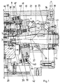
- first subassembly 1 comprised of a plurality of, for example five, cylinder-piston units 2, which units are arranged at a radial distance from and parallel to a central longitudinal axis 3 as well as being circumferentially offset, relative to each other around the central axis by an appropriate angle, for example 72°.
- Each cylinder-piston unit is comprised of a piston 4 slidably arranged in a cylinder 5 with piston 4 and cylinder 5 being shown in axial sections only over a part of their axial length.
- Specific design details of cylinder 5 and piston 4 are only of minimal interest in the present context, since cylinder-piston units 2 may be of any type well known in the art.
- a pretensioned return coil or compression spring 6 surrounds cylinder 5 and acts through a sleeve 7 against a radially projecting bottom flange 8 of piston 4, thus tending to push piston 4 in its restoring or cylinder-filling direction (in the Figures from the left to the right).
- the inner (in Fig. 2 the left) end of spring 6 abuts on the right end face of a support sleeve 9 fixedly retained in an axial bore of a machine housing 10.
- Support sleeve 9, on its right side, is fixedly secured to the left end portion of cylinder 5.
- housing 10 The left end face of housing 10 is tightly connected, e.g. by means of highly pretensioned axial screws 11, with a head-subassembly 12, which among other parts houses a valve assembly 13 and a filler or feed pump 14 attached to a section 15 of a drive shaft 16 (Fig.1).
- Drive shaft section 15 is coupled, by means of a toothed-clutch 17, to a central drive shaft section 18.
- Filler pump 14 serves to enhance the input hydraulic pressure for the cylinder-piston units 2 to a value sufficient for avoiding cavitation.
- Drive shaft section 18 also drives a lubricant pump 19, which in turn feeds a lubricant channel system 20 via a lubricant filter 21.
- each cylinder-piston unit 2 Coaxially attached to each cylinder-piston unit 2 is a combined inlet-outlet valve 22 having an inlet side 23 connected, via an inlet channel system 24, to the output 25 of filler pump 14.
- Pump 14 e.g. is of the well-known "side-channel" type and will not be described in detail here since it is not material for the essence or function of the invention.
- Filler pump 14 is connected, via an input 26, to a non-illustrated external low-pressure hydraulic feed system.
- Inlet/outlet valve 22 further has an output side 27, connected through an output channel system 28, to a non-illustrated external high-pressure hydraulic system.
- Valve 22 has substantially coaxial internal flow channel systems and spring-loaded check valve members for both flow directions, i.e.
- valve 22 is of no specific interest for the invention and thus will not be described in further detail. In principle, instead of the noted example of the combined inlet/outlet valve 22 described here, other conventional and well-known valve types may be used.
- a second subassembly 29 is rotatably arranged relative to first subassembly 1.
- Subassembly 29 is in force-transmitting connection with cylinder-piston units 2 within the range of a coupling plane 30, arranged at least approximately right-angled or perpendicular to the central longitudinal axis 3, so as to absorb the oscillating drive forces produced by cylinder-piston units 2.
- Subassembly 29 is constructed as a driving subassembly that is rotatably arranged in housing 10 and coupled with a main section 31 of drive shaft 16.
- Drive shaft sections 18 and 31 are coupled by means of any type of a conventional clutch.
- cylinder-piston subassembly 2 may be designed as a rotating drum, i.e. in the sense of previously-noted machine types II. and III. In the latter case, this subassembly would be a substantially torqueless rotating unit.
- Driving subassembly 29 includes a bearing assembly comprising two first bearings 33, 34, which act at least substantially in the radial direction and are arranged at a predetermined axial distance or spacing from each other, and a swivel-joint or pivot-type second bearing 35 acting both axially and radially.
- bearings 33 and 34 may take the form of axially movably cylindrical roller bearings, while bearing 35 may be a mainly axially acting spherical roller bearing.
- the swivel or pivot center 36 of second bearing 35 is located at about the axial mid-point (center-to-center distance) 37 between the mid-points 38, of the bearing axial width 39, of axially spaced first bearings 33, 34.
- Subassemblies 1 and 29 are arranged so as to be rotatable, in relation to each other, around their common central axis 3. Only one of these subassemblies, here subassembly 29, is arranged to be rotatable in housing 10 and functions as a driving subassembly, coupled with the drive shaft 16. However, as already noted earlier, a design according to machine type III. may also be utilized.
- a disk-like coupling member 40 is rotatably connected to second subassembly 29 around a swash axis 41, which is arranged at an angle relative to the central axis 3.
- Coupling member 40 is further connected to first subassembly 1 in a manner so as to be blocked against continuous rotation around central axis 3, and is connected in a force-transmitting manner with the cylinder-piston units 2 within the range of coupling plane 30.
- Coupling plane 30 is arranged at least approximately right-angled or perpendicularly to swash axis 41.
- coupling member 40 takes over or absorbs the substantially axial, oscillating drive forces produced by cylinder-piston units 2 and transmits such forces to second subassembly 29. It should be understood that coupling member 40 can also be regarded as a part of second subassembly 29.
- holding device 42 is a cardan type of device comprising a cardan ring 43, which extends along the external perimeter of coupling member 40 and which is connected with each of coupling members 40 and subassembly 1 by means of a pair of diametrical pivots 44.
- cardan ring 43 is fixed to housing 10 by means of a further pair of non-illustrated diametrical pivots.
- double-jointed rods 45 preferably double ball-jointed rods, are provided for the force transmission between cylinder-piston units 2 and coupling member 40.
- Each of double-jointed rods 45 is connected by means of a first joint 46 to a corresponding piston 2 and by means of a second joint 47 to a corresponding junction assembly 48 of coupling member 40.
- drive shaft 16 is comprised of three rotationally coupled sections 31, 18 and 15.
- Drive shaft 16 extends coaxially with central axis 3 from its drive input end 49 through a corresponding central opening of first subassembly 1 and of housing 10 to head-subassembly 12 with feed pump 14 and valve assembly 13.
- valve assembly then must be positively coupled to and synchronized with the rotation of the drive shaft, which then functions as a power output shaft.
- the filler pump can be omitted or replaced by other useful auxiliary units.
- the angle between the swash axis and the central axis may be predetermined so as to be of a fixed acute angle value or so as to be variably adjustable in operation between 0° and a maximum acute angle value, and this with angle variation to both sides of the zero angle value if desired for purposes of hydraulic flow direction reversal.
- Such variation obviously entails a corresponding variation of the angle between the coupling plane and the central axis, which is the complementary angle to the one between the swash axis and the central axis and determinative for the magnitude of the piston stroke.
- This type of of swash plate axial piston machines with variable swash-angle is well known in the art per se.
- the realization of the subject of the present invention for such variable-swash-angle machines can be established by usual structures near at hand and needs no further explanation.
Landscapes
- Engineering & Computer Science (AREA)
- Mechanical Engineering (AREA)
- General Engineering & Computer Science (AREA)
- Chemical & Material Sciences (AREA)
- Combustion & Propulsion (AREA)
- Reciprocating Pumps (AREA)
- Details Of Reciprocating Pumps (AREA)
Claims (5)
- Axialpumpe, insbesondere Hochdruckpumpe, umfassend:a) eine erste Baugruppe (1) mit einer Mehrzahl von Zylinder-Kolbeneinheiten (2), die mit Abstand von und parallel oder unter einem spitzen Winkel zu einer Zentralachse (3) sowie gegeneinander um diese Zentralachse unter einem vorgegebenen Winkel in Umfangsrichtung versetzt angeordnet sind;b) eine koaxial mit der Zentralachse und um diese drehbar auf einer Antriebswelle (16) angeordnete zweite Baugruppe (29), die derart in kraftübertragender Verbindung mit den Zylinder-Kolbeneinheiten steht, dass sie deren oszillierende Antriebskräfte aufnimmt;c) wobei sich die Antriebswelle koaxial mit der Zentralachse von einem Antriebs-Eingangsende (49) durch eine entsprechende Zentralöffnung der ersten Baugruppe zu einer Koptbaugruppe (12) erstreckt;
gekennzeichnet dadurch,d) dass die erste Baugruppe eine Schmierpumpe (19) aufweist, die angrenzend an die Zentralachse (3) und in einem radialen Raum zwisehen den Zylinder-Kolbeneinheiten (2) derart angeordnet ist, dass sie sich über eine von einer Axiallänge der Zylinder-Kolbeneinheiten bedeckte Axiallänge erstreckt;e) dass die Schmierpumpe (19) mit wenigstend einem sich im wesentlichen radial erstreckenden Schmierkanal verbunden ist;f) dass die Antriebswelle wenigstens zwei drehgekuppelte Längsabschnitte aufweist und dass die Schmierpumpe auf einem (18) dieser Absehnitte und in Dreh-Antriebsverbindung mit diesem angeordnet ist. - Hydraulische Axialpumpe gemäss Anspruch 1, umfassend eine Kopfbaugruppe (12) mit einer mit der Antriebswelle gekuppelten Vorfüllpumpe (14), wobei ein Strömungspfad dieser Vorfüllpumpe in Reihe mit einem Hauptströmungspfad der hydraulischen Axial-Förderpumpe angeordnet ist, um den Zylinder-Kolbeneinheiten im wesentlichen einen vollständigen Zufluss unter einem erhöhten, zur Vermeidung von Kavitation ausreichenden Eingangsdruck zu liefern.
- Hydraulische Axialpumpe gemäss Anspruch 2, worin die Kopfbaugruppe des weiteren eine in den Hauptströmungspfad. der hydraulischen Axialpumpe eingeschaltete Ventilanordnung (13) aufweist und worin sich die Vorfüllpumpe (14) axial vor dieser Ventilanordnung befindet, wobei sich wenigstens ein Auslass (25) der Vorfüllpumpe zunächst der Einlassventilanordnung (13) befindet.
- Hydraulische Axialpumpe gemäss Anspruch 3, worin die Vorfüllpumpe (14) vom Seitenkanal-Typ ist und sich mit einem Seitenkanal sowie mindestens einem Auslass (25) zunächst der Einlassvenmtilanordnung befindet.
- Hydraulische Axialpumpe gemäss einem der Ansprüche 2 bis 4, worin die Schmierpumpe (19) und die Vorfüllpumpe (14) auf gesonderten Längsabschnitten (15, 18) der Antriebswelle angeordnet sind, wobei diese Antriebswellenabschnitte koaxial angeordnet und miteinander in Antriebsverbindung gekuppelt sind.
Applications Claiming Priority (4)
| Application Number | Priority Date | Filing Date | Title |
|---|---|---|---|
| CH256692 | 1992-08-06 | ||
| CH2566/92 | 1992-08-06 | ||
| CH256692 | 1992-08-06 | ||
| PCT/EP1993/002106 WO1994003708A1 (en) | 1992-08-06 | 1993-08-06 | Axial piston machine, in particular an axial piston pump or an axial piston motor |
Publications (2)
| Publication Number | Publication Date |
|---|---|
| EP0705380A1 EP0705380A1 (de) | 1996-04-10 |
| EP0705380B1 true EP0705380B1 (de) | 2000-04-26 |
Family
ID=4236691
Family Applications (1)
| Application Number | Title | Priority Date | Filing Date |
|---|---|---|---|
| EP93917765A Expired - Lifetime EP0705380B1 (de) | 1992-08-06 | 1993-08-06 | Axialkolbenmaschine, insbesondere für eine axialkolbenpumpe oder einen axialkolbenmotor |
Country Status (10)
| Country | Link |
|---|---|
| EP (1) | EP0705380B1 (de) |
| JP (1) | JPH08502797A (de) |
| KR (1) | KR100316356B1 (de) |
| CN (1) | CN1057584C (de) |
| AT (1) | ATE192214T1 (de) |
| AU (1) | AU689076B2 (de) |
| CA (1) | CA2141812A1 (de) |
| DE (1) | DE69328499T2 (de) |
| WO (1) | WO1994003708A1 (de) |
| ZA (1) | ZA935640B (de) |
Families Citing this family (5)
| Publication number | Priority date | Publication date | Assignee | Title |
|---|---|---|---|---|
| DE102010026157A1 (de) * | 2010-07-06 | 2012-01-12 | Robert Bosch Gmbh | Hydrostatische Maschine, insbesondere Axialkolbenmaschine |
| FR3007084B1 (fr) * | 2013-06-12 | 2015-06-26 | Technoboost | Machine hydraulique comportant des cylindres disposant d'ouvertures decalees angulairement |
| DE102013213614A1 (de) * | 2013-07-11 | 2015-01-15 | Volkswagen Aktiengesellschaft | Axialkolbenmaschine |
| DE102014212600B4 (de) | 2014-06-30 | 2019-04-25 | Danfoss Power Solutions Gmbh & Co. Ohg | Integrierte Schmierpumpe |
| US10006449B2 (en) | 2015-01-14 | 2018-06-26 | Caterpillar Inc. | Bearing arrangement for cryogenic pump |
Citations (8)
| Publication number | Priority date | Publication date | Assignee | Title |
|---|---|---|---|---|
| US1910054A (en) * | 1926-08-30 | 1933-05-23 | Automotive Engineering Corp | Power transmission |
| US2737895A (en) * | 1952-11-19 | 1956-03-13 | Oilgear Co | Axial type pump |
| US2868443A (en) * | 1954-06-24 | 1959-01-13 | Gen Motors Corp | Refrigerating apparatus |
| US3486335A (en) * | 1967-10-02 | 1969-12-30 | Towmotor Corp | Common valve plate hydrostatic transmission |
| US3514223A (en) * | 1968-08-19 | 1970-05-26 | Applied Power Ind Inc | Hydraulic pump |
| US4041703A (en) * | 1976-05-24 | 1977-08-16 | Eaton Corporation | Hydrostatic transmission with integral auxiliary pump |
| US4281971A (en) * | 1979-07-31 | 1981-08-04 | Abex Corporation | Inlet inducer-impeller for piston pump |
| US4858480A (en) * | 1984-11-20 | 1989-08-22 | Hydromatic Gmbh | Swash plate swivel bearing for a hydraulic axial piston machine |
Family Cites Families (5)
| Publication number | Priority date | Publication date | Assignee | Title |
|---|---|---|---|---|
| US2424660A (en) * | 1945-05-07 | 1947-07-29 | Frank C Howard | Wobble plate engine |
| US3092307A (en) * | 1959-07-15 | 1963-06-04 | Gen Motors Corp | Compressor |
| DE1817123C3 (de) * | 1968-12-27 | 1979-04-26 | Hermann 7742 St Georgen Papst | Axialkolbenmaschine mit mehreren Kolben |
| FR2044182A5 (de) * | 1969-05-12 | 1971-02-19 | Corpet Louvet & Cie | |
| FR2588617B1 (fr) * | 1985-10-14 | 1989-11-24 | Drevet Michel | Machine rotative a pistons et a barillet avec rotule de centrage fixe. |
-
1993
- 1993-08-04 ZA ZA935640A patent/ZA935640B/xx unknown
- 1993-08-05 CN CN93109269A patent/CN1057584C/zh not_active Expired - Fee Related
- 1993-08-06 EP EP93917765A patent/EP0705380B1/de not_active Expired - Lifetime
- 1993-08-06 AU AU47083/93A patent/AU689076B2/en not_active Ceased
- 1993-08-06 AT AT93917765T patent/ATE192214T1/de not_active IP Right Cessation
- 1993-08-06 WO PCT/EP1993/002106 patent/WO1994003708A1/en not_active Ceased
- 1993-08-06 CA CA002141812A patent/CA2141812A1/en not_active Abandoned
- 1993-08-06 KR KR1019950700427A patent/KR100316356B1/ko not_active Expired - Fee Related
- 1993-08-06 DE DE69328499T patent/DE69328499T2/de not_active Expired - Fee Related
- 1993-08-06 JP JP6505028A patent/JPH08502797A/ja active Pending
Patent Citations (8)
| Publication number | Priority date | Publication date | Assignee | Title |
|---|---|---|---|---|
| US1910054A (en) * | 1926-08-30 | 1933-05-23 | Automotive Engineering Corp | Power transmission |
| US2737895A (en) * | 1952-11-19 | 1956-03-13 | Oilgear Co | Axial type pump |
| US2868443A (en) * | 1954-06-24 | 1959-01-13 | Gen Motors Corp | Refrigerating apparatus |
| US3486335A (en) * | 1967-10-02 | 1969-12-30 | Towmotor Corp | Common valve plate hydrostatic transmission |
| US3514223A (en) * | 1968-08-19 | 1970-05-26 | Applied Power Ind Inc | Hydraulic pump |
| US4041703A (en) * | 1976-05-24 | 1977-08-16 | Eaton Corporation | Hydrostatic transmission with integral auxiliary pump |
| US4281971A (en) * | 1979-07-31 | 1981-08-04 | Abex Corporation | Inlet inducer-impeller for piston pump |
| US4858480A (en) * | 1984-11-20 | 1989-08-22 | Hydromatic Gmbh | Swash plate swivel bearing for a hydraulic axial piston machine |
Also Published As
| Publication number | Publication date |
|---|---|
| CA2141812A1 (en) | 1994-02-17 |
| CN1104300A (zh) | 1995-06-28 |
| DE69328499T2 (de) | 2000-12-21 |
| JPH08502797A (ja) | 1996-03-26 |
| EP0705380A1 (de) | 1996-04-10 |
| ATE192214T1 (de) | 2000-05-15 |
| AU4708393A (en) | 1994-03-03 |
| KR100316356B1 (ko) | 2002-02-28 |
| KR950703114A (ko) | 1995-08-23 |
| WO1994003708A1 (en) | 1994-02-17 |
| AU689076B2 (en) | 1998-03-26 |
| CN1057584C (zh) | 2000-10-18 |
| ZA935640B (en) | 1995-08-08 |
| DE69328499D1 (de) | 2000-05-31 |
Similar Documents
| Publication | Publication Date | Title |
|---|---|---|
| US3319575A (en) | Piston | |
| US4546692A (en) | Radial bearing for drive plate of inclined-axis type axial piston machine | |
| US3255706A (en) | Rotary radial piston machines with tangential balancing recesses for the pressure balance of the pistons | |
| JP2009529619A (ja) | アキシャルプランジャーポンプ又はモータ | |
| US3139038A (en) | Engine | |
| US5738000A (en) | Axial piston machine with guides for the pistons contained therein | |
| CA2189846A1 (en) | Continuously variable hydrostatic transmission | |
| GB1340661A (en) | Compressor assembly | |
| US3191543A (en) | Pump or motor device | |
| US6206650B1 (en) | Variable axial piston displacement machine with maximized swivel angle | |
| EP0491078B1 (de) | Hydraulisches Energiegetriebe | |
| US3382793A (en) | Axial piston hydraulic unit | |
| US3661055A (en) | Multi-cylinder barrel hydraulic pumps or motors | |
| EP0705380B1 (de) | Axialkolbenmaschine, insbesondere für eine axialkolbenpumpe oder einen axialkolbenmotor | |
| AU2004317667A1 (en) | Long-piston hydraulic machines | |
| US4738185A (en) | Swash plate-type pump-motor | |
| US3405646A (en) | Hydraulic pumps or motors | |
| US5850775A (en) | Pump piston | |
| US5842343A (en) | Hydraulic axial discharge pump | |
| US3181475A (en) | Wobble plate pump | |
| US3828657A (en) | Piston for swash plate pump | |
| US3543649A (en) | Axial piston pump or motor device | |
| US3304884A (en) | Hydraulic fluid energy translating device | |
| US6358018B1 (en) | Hydraulic rotating axial piston engine | |
| US4800800A (en) | Fluid pressure translating device |
Legal Events
| Date | Code | Title | Description |
|---|---|---|---|
| PUAI | Public reference made under article 153(3) epc to a published international application that has entered the european phase |
Free format text: ORIGINAL CODE: 0009012 |
|
| 17P | Request for examination filed |
Effective date: 19950305 |
|
| AK | Designated contracting states |
Kind code of ref document: A1 Designated state(s): AT BE CH DE DK ES FR GB GR IE IT LI LU MC NL PT SE |
|
| 17Q | First examination report despatched |
Effective date: 19960506 |
|
| GRAG | Despatch of communication of intention to grant |
Free format text: ORIGINAL CODE: EPIDOS AGRA |
|
| GRAG | Despatch of communication of intention to grant |
Free format text: ORIGINAL CODE: EPIDOS AGRA |
|
| GRAG | Despatch of communication of intention to grant |
Free format text: ORIGINAL CODE: EPIDOS AGRA |
|
| GRAH | Despatch of communication of intention to grant a patent |
Free format text: ORIGINAL CODE: EPIDOS IGRA |
|
| GRAH | Despatch of communication of intention to grant a patent |
Free format text: ORIGINAL CODE: EPIDOS IGRA |
|
| GRAA | (expected) grant |
Free format text: ORIGINAL CODE: 0009210 |
|
| AK | Designated contracting states |
Kind code of ref document: B1 Designated state(s): AT BE CH DE DK ES FR GB GR IE IT LI LU MC NL PT SE |
|
| PG25 | Lapsed in a contracting state [announced via postgrant information from national office to epo] |
Ref country code: IT Free format text: LAPSE BECAUSE OF FAILURE TO SUBMIT A TRANSLATION OF THE DESCRIPTION OR TO PAY THE FEE WITHIN THE PRESCRIBED TIME-LIMIT;WARNING: LAPSES OF ITALIAN PATENTS WITH EFFECTIVE DATE BEFORE 2007 MAY HAVE OCCURRED AT ANY TIME BEFORE 2007. THE CORRECT EFFECTIVE DATE MAY BE DIFFERENT FROM THE ONE RECORDED. Effective date: 20000426 Ref country code: GR Free format text: LAPSE BECAUSE OF NON-PAYMENT OF DUE FEES Effective date: 20000426 Ref country code: ES Free format text: THE PATENT HAS BEEN ANNULLED BY A DECISION OF A NATIONAL AUTHORITY Effective date: 20000426 |
|
| REF | Corresponds to: |
Ref document number: 192214 Country of ref document: AT Date of ref document: 20000515 Kind code of ref document: T |
|
| REG | Reference to a national code |
Ref country code: CH Ref legal event code: EP |
|
| REF | Corresponds to: |
Ref document number: 69328499 Country of ref document: DE Date of ref document: 20000531 |
|
| REG | Reference to a national code |
Ref country code: IE Ref legal event code: FG4D |
|
| PG25 | Lapsed in a contracting state [announced via postgrant information from national office to epo] |
Ref country code: SE Free format text: LAPSE BECAUSE OF FAILURE TO SUBMIT A TRANSLATION OF THE DESCRIPTION OR TO PAY THE FEE WITHIN THE PRESCRIBED TIME-LIMIT Effective date: 20000726 Ref country code: PT Free format text: LAPSE BECAUSE OF FAILURE TO SUBMIT A TRANSLATION OF THE DESCRIPTION OR TO PAY THE FEE WITHIN THE PRESCRIBED TIME-LIMIT Effective date: 20000726 Ref country code: DK Free format text: LAPSE BECAUSE OF FAILURE TO SUBMIT A TRANSLATION OF THE DESCRIPTION OR TO PAY THE FEE WITHIN THE PRESCRIBED TIME-LIMIT Effective date: 20000726 |
|
| PG25 | Lapsed in a contracting state [announced via postgrant information from national office to epo] |
Ref country code: IE Free format text: LAPSE BECAUSE OF NON-PAYMENT OF DUE FEES Effective date: 20000807 |
|
| ET | Fr: translation filed | ||
| PG25 | Lapsed in a contracting state [announced via postgrant information from national office to epo] |
Ref country code: MC Free format text: THE PATENT HAS BEEN ANNULLED BY A DECISION OF A NATIONAL AUTHORITY Effective date: 20000831 |
|
| PLBE | No opposition filed within time limit |
Free format text: ORIGINAL CODE: 0009261 |
|
| STAA | Information on the status of an ep patent application or granted ep patent |
Free format text: STATUS: NO OPPOSITION FILED WITHIN TIME LIMIT |
|
| 26N | No opposition filed | ||
| REG | Reference to a national code |
Ref country code: IE Ref legal event code: MM4A |
|
| REG | Reference to a national code |
Ref country code: GB Ref legal event code: IF02 |
|
| PGFP | Annual fee paid to national office [announced via postgrant information from national office to epo] |
Ref country code: BE Payment date: 20020726 Year of fee payment: 10 |
|
| PGFP | Annual fee paid to national office [announced via postgrant information from national office to epo] |
Ref country code: AT Payment date: 20020813 Year of fee payment: 10 |
|
| PG25 | Lapsed in a contracting state [announced via postgrant information from national office to epo] |
Ref country code: AT Free format text: LAPSE BECAUSE OF NON-PAYMENT OF DUE FEES Effective date: 20030806 |
|
| PGFP | Annual fee paid to national office [announced via postgrant information from national office to epo] |
Ref country code: GB Payment date: 20030806 Year of fee payment: 11 |
|
| PGFP | Annual fee paid to national office [announced via postgrant information from national office to epo] |
Ref country code: LU Payment date: 20030825 Year of fee payment: 11 |
|
| PGFP | Annual fee paid to national office [announced via postgrant information from national office to epo] |
Ref country code: FR Payment date: 20030826 Year of fee payment: 11 |
|
| PG25 | Lapsed in a contracting state [announced via postgrant information from national office to epo] |
Ref country code: BE Free format text: LAPSE BECAUSE OF NON-PAYMENT OF DUE FEES Effective date: 20030831 |
|
| PGFP | Annual fee paid to national office [announced via postgrant information from national office to epo] |
Ref country code: NL Payment date: 20030831 Year of fee payment: 11 |
|
| PGFP | Annual fee paid to national office [announced via postgrant information from national office to epo] |
Ref country code: CH Payment date: 20031008 Year of fee payment: 11 |
|
| PGFP | Annual fee paid to national office [announced via postgrant information from national office to epo] |
Ref country code: DE Payment date: 20031021 Year of fee payment: 11 |
|
| BERE | Be: lapsed |
Owner name: *HYDROWATT SYSTEMS LTD Effective date: 20030831 |
|
| PG25 | Lapsed in a contracting state [announced via postgrant information from national office to epo] |
Ref country code: LU Free format text: LAPSE BECAUSE OF NON-PAYMENT OF DUE FEES Effective date: 20040806 Ref country code: GB Free format text: LAPSE BECAUSE OF NON-PAYMENT OF DUE FEES Effective date: 20040806 |
|
| PG25 | Lapsed in a contracting state [announced via postgrant information from national office to epo] |
Ref country code: LI Free format text: LAPSE BECAUSE OF NON-PAYMENT OF DUE FEES Effective date: 20040831 Ref country code: CH Free format text: LAPSE BECAUSE OF NON-PAYMENT OF DUE FEES Effective date: 20040831 |
|
| PG25 | Lapsed in a contracting state [announced via postgrant information from national office to epo] |
Ref country code: NL Free format text: LAPSE BECAUSE OF NON-PAYMENT OF DUE FEES Effective date: 20050301 Ref country code: DE Free format text: LAPSE BECAUSE OF NON-PAYMENT OF DUE FEES Effective date: 20050301 |
|
| GBPC | Gb: european patent ceased through non-payment of renewal fee |
Effective date: 20040806 |
|
| REG | Reference to a national code |
Ref country code: CH Ref legal event code: PL |
|
| PG25 | Lapsed in a contracting state [announced via postgrant information from national office to epo] |
Ref country code: FR Free format text: LAPSE BECAUSE OF NON-PAYMENT OF DUE FEES Effective date: 20050429 |
|
| NLV4 | Nl: lapsed or anulled due to non-payment of the annual fee |
Effective date: 20050301 |
|
| REG | Reference to a national code |
Ref country code: FR Ref legal event code: ST |