EP0704635A1 - Rolled sleeve for a plain bearing - Google Patents
Rolled sleeve for a plain bearing Download PDFInfo
- Publication number
- EP0704635A1 EP0704635A1 EP95113106A EP95113106A EP0704635A1 EP 0704635 A1 EP0704635 A1 EP 0704635A1 EP 95113106 A EP95113106 A EP 95113106A EP 95113106 A EP95113106 A EP 95113106A EP 0704635 A1 EP0704635 A1 EP 0704635A1
- Authority
- EP
- European Patent Office
- Prior art keywords
- bushing
- rolled
- profile
- entire
- angle
- Prior art date
- Legal status (The legal status is an assumption and is not a legal conclusion. Google has not performed a legal analysis and makes no representation as to the accuracy of the status listed.)
- Granted
Links
- 210000001503 joint Anatomy 0.000 claims description 7
- 239000000463 material Substances 0.000 claims description 7
- 238000012423 maintenance Methods 0.000 claims description 3
- 239000003831 antifriction material Substances 0.000 abstract 1
- 239000010410 layer Substances 0.000 description 6
- 239000012791 sliding layer Substances 0.000 description 4
- 229910000831 Steel Inorganic materials 0.000 description 3
- 239000010959 steel Substances 0.000 description 3
- 238000010276 construction Methods 0.000 description 1
- 239000002184 metal Substances 0.000 description 1
- 230000002093 peripheral effect Effects 0.000 description 1
Images

Classifications
-
- F—MECHANICAL ENGINEERING; LIGHTING; HEATING; WEAPONS; BLASTING
- F16—ENGINEERING ELEMENTS AND UNITS; GENERAL MEASURES FOR PRODUCING AND MAINTAINING EFFECTIVE FUNCTIONING OF MACHINES OR INSTALLATIONS; THERMAL INSULATION IN GENERAL
- F16C—SHAFTS; FLEXIBLE SHAFTS; ELEMENTS OR CRANKSHAFT MECHANISMS; ROTARY BODIES OTHER THAN GEARING ELEMENTS; BEARINGS
- F16C33/00—Parts of bearings; Special methods for making bearings or parts thereof
- F16C33/02—Parts of sliding-contact bearings
- F16C33/04—Brasses; Bushes; Linings
- F16C33/06—Sliding surface mainly made of metal
- F16C33/10—Construction relative to lubrication
- F16C33/1025—Construction relative to lubrication with liquid, e.g. oil, as lubricant
- F16C33/106—Details of distribution or circulation inside the bearings, e.g. details of the bearing surfaces to affect flow or pressure of the liquid
- F16C33/1065—Grooves on a bearing surface for distributing or collecting the liquid
-
- F—MECHANICAL ENGINEERING; LIGHTING; HEATING; WEAPONS; BLASTING
- F16—ENGINEERING ELEMENTS AND UNITS; GENERAL MEASURES FOR PRODUCING AND MAINTAINING EFFECTIVE FUNCTIONING OF MACHINES OR INSTALLATIONS; THERMAL INSULATION IN GENERAL
- F16C—SHAFTS; FLEXIBLE SHAFTS; ELEMENTS OR CRANKSHAFT MECHANISMS; ROTARY BODIES OTHER THAN GEARING ELEMENTS; BEARINGS
- F16C17/00—Sliding-contact bearings for exclusively rotary movement
- F16C17/12—Sliding-contact bearings for exclusively rotary movement characterised by features not related to the direction of the load
- F16C17/18—Sliding-contact bearings for exclusively rotary movement characterised by features not related to the direction of the load with floating brasses or brushing, rotatable at a reduced speed
-
- F—MECHANICAL ENGINEERING; LIGHTING; HEATING; WEAPONS; BLASTING
- F16—ENGINEERING ELEMENTS AND UNITS; GENERAL MEASURES FOR PRODUCING AND MAINTAINING EFFECTIVE FUNCTIONING OF MACHINES OR INSTALLATIONS; THERMAL INSULATION IN GENERAL
- F16C—SHAFTS; FLEXIBLE SHAFTS; ELEMENTS OR CRANKSHAFT MECHANISMS; ROTARY BODIES OTHER THAN GEARING ELEMENTS; BEARINGS
- F16C33/00—Parts of bearings; Special methods for making bearings or parts thereof
- F16C33/02—Parts of sliding-contact bearings
- F16C33/04—Brasses; Bushes; Linings
Definitions
- the invention relates to a rolled bushing for plain bearings, made from a band section (board) of a maintenance-free or low-maintenance sliding material, which is round in the installed state, which has a butt joint which extends over the entire bushing width and which is closed in the installed state, and the outer surface of which is an over has the entire profile running profile.
- DE-A-24 06 658 describes a resilient bearing bush, which alternately has an area of smaller diameter in its circumferential direction, which is resiliently pressed against the circumferential surface of the shaft and lies radially inward at a distance from the inner periphery of the housing. and has an area of larger radius which is resiliently pressed against the inner periphery of the housing and is located radially outward at a distance from the peripheral surface of the shaft.
- DE-A-23 47 548 describes a plain bearing bush in which plastic pads are alternately applied on the outside and on the inside in the circumferential direction.
- a plain bearing bush is known, the shape of which in the unclamped state on the outside diameter and on The inside diameter differs from the circular shape. This deviating polygonal shape is achieved through targeted reshaping and through a roof shape in the area of the butt joint.
- This plain bearing bush tends to seize in the area of the closed butt joint when pressed into a bearing housing; this applies in particular to bearing housings made of light metal. It is a further disadvantage that such a plain bearing bush must be aligned specifically after the butt joint when installed in the bearing housing; this results in an increased assembly effort.
- Fig. 1 shows an isometric view of a rolled plain bearing bush with a wall thickness of 1.0 mm, consisting of a support layer (1) made of steel and a sliding layer (2) made of a maintenance-free sliding material.
- a support layer (1) made of steel
- a sliding layer (2) made of a maintenance-free sliding material.
- On the outer surface of the support layer there is a trapezoidal profile with regular division, in which the mean arc length of a profile elevation (3) and a profile depression (4) is of the same length.
- the trapezoidal profile forms an angle of 10 ° with the plane running through the longitudinal axis of the plain bearing bush.
- FIG. 2 shows an enlarged representation of the detail "X" of FIG. 1.
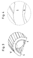
- FIG. 3 shows a rolled plain bearing bush with a wall thickness of 1.0 mm, consisting of a support layer (5) made of steel and a sliding layer (6) made of a maintenance-free sliding material. Both on the outer lateral surface of the support layer (5) and on the inner lateral surface of the sliding layer (6) a trapezoidal profile with regular division is attached, which forms an angle of 10 ° with the plane including the longitudinal axis of the plain bearing bush.
- FIG. 4 shows an enlarged representation of the detail "Y" of FIG. 3.
- Fig. 5 the profile of the profile on the outer surface of the plain bearing bush is shown as a detail.
- the profiling forms an angle (a) of 16 ° with a plane through the longitudinal axis of the plain bearing bush.
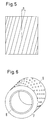
- FIG. 6 shows the isometric representation of a rolled plain bearing bush with a wall thickness of 1.0 mm.
- a sliding layer (8) of a maintenance-free sliding material is located on a steel support layer (7).
- the outer circumferential surface of the support layer (7) is provided with frustoconical ridges (9) arranged on lines. The lines run parallel at an angle of 20 ° to a plane enclosing the longitudinal axis of the plain bearing bush.
Landscapes
- Engineering & Computer Science (AREA)
- General Engineering & Computer Science (AREA)
- Mechanical Engineering (AREA)
- Chemical & Material Sciences (AREA)
- Oil, Petroleum & Natural Gas (AREA)
- Sliding-Contact Bearings (AREA)
- Springs (AREA)
Abstract
Description
Die Erfindung betrifft eine gerollte Buchse für Gleitlager, hergestellt aus einem Bandabschnitt (Platine) eines wartungsfreien bzw. wartungsarmen Gleitwerkstoffs, die im eingebauten Zustand rund ist, die eine über die ganze Buchsenbreite verlaufende, im eingebauten Zustand geschlossene Stoßfuge besitzt und deren äußere Mantelfläche ein über die ganze Buchsenbreite verlaufendes Profil aufweist.The invention relates to a rolled bushing for plain bearings, made from a band section (board) of a maintenance-free or low-maintenance sliding material, which is round in the installed state, which has a butt joint which extends over the entire bushing width and which is closed in the installed state, and the outer surface of which is an over has the entire profile running profile.
Bei zahlreichen Gleitlagerungen, beispielsweise in Kraftfahrzeugen, besteht die Forderung nach vollständiger Spielfreiheit über die gesamte Lebensdauer der Gleitlagerung.With numerous plain bearings, for example in motor vehicles, there is a demand for complete freedom from play over the entire life of the plain bearing.
Für diese Zwecke sind mehrere Bauarten von Gleitlagerbuchsen bekannt. So ist z.B. in der DE-A-24 06 658 eine federnde Lagerbuchse beschrieben, die abwechselnd in ihrer Umfangsrichtung einen Bereich kleineren Halbmessers, der federnd gegen die Umfangsfläche der Welle gedrückt wird und radial nach innen im Abstand von der inneren Peripherie des Gehäuses liegt, und einen Bereich größeren Halbmessers hat, der federnd gegen die innere Peripherie des Gehäuses gedrückt wird und radial nach außen im Abstand von der Umfangsfläche der Welle liegt. Die DE-A-23 47 548 beschreibt eine Gleitlagerbuchse, bei der auf der Außenseite und auf der Innenseite in Umfangsrichtung wechselweise Kunststoffpolster aufgebracht sind. Aus der WO 93/22574 ist eine Gleitlagerbuchse bekannt, deren Form im nicht eingespannten Zustand am Außendurchmesser und am Innendurchmesser von der kreisrunden Form abweicht. Diese abweichende polygonale Form wird erreicht durch gezielte Umformung und durch eine Dachform im Bereich der Stoßfuge. Diese Gleitlagerbuchse neigt beim Einpressen in ein Lagergehäuse zum Fressen im Bereich der geschlossenen Stoßfuge; insbesondere trifft dieses bei aus Leichtmetall gefertigten Lagergehäusen zu. Es ist weiter von Nachteil, daß eine solche Gleitlagerbuchse beim Einbau in das Lagergehäuse gezielt nach der Stoßfuge ausgerichtet werden muß; das hat einen erhöhten Montageaufwand zur Folge. Bei einer in der DE-A-39 22 052 beschriebenen wartungsfreien Gleitlagerbuchse für Kraftwagen-Türscharniere ist mindestens die dem Scharnierstift zugeordnete Oberfläche der Gleitlagerbuchse mit einer durch zueinander parallel laufende, linienförmige Erhöhungen und Vertiefungen gebildete Profilierung versehen. Dadurch soll die Einhaltung engster Lagerspiele erreicht werden. Es ist jedoch von Nachteil, daß durch die linienförmigen Erhöhungen im Innendurchmesser die geforderte Spielfreiheit über die gesamte Lebensdauer der Gleitlagerbuchse nicht gewährleistet ist.For this purpose, several types of plain bearing bushes are known. For example, DE-A-24 06 658 describes a resilient bearing bush, which alternately has an area of smaller diameter in its circumferential direction, which is resiliently pressed against the circumferential surface of the shaft and lies radially inward at a distance from the inner periphery of the housing. and has an area of larger radius which is resiliently pressed against the inner periphery of the housing and is located radially outward at a distance from the peripheral surface of the shaft. DE-A-23 47 548 describes a plain bearing bush in which plastic pads are alternately applied on the outside and on the inside in the circumferential direction. From WO 93/22574 a plain bearing bush is known, the shape of which in the unclamped state on the outside diameter and on The inside diameter differs from the circular shape. This deviating polygonal shape is achieved through targeted reshaping and through a roof shape in the area of the butt joint. This plain bearing bush tends to seize in the area of the closed butt joint when pressed into a bearing housing; this applies in particular to bearing housings made of light metal. It is a further disadvantage that such a plain bearing bush must be aligned specifically after the butt joint when installed in the bearing housing; this results in an increased assembly effort. In the case of a maintenance-free plain bearing bush for motor vehicle door hinges described in DE-A-39 22 052, at least the surface of the plain bearing bush assigned to the hinge pin is provided with a profile formed by parallel, linear elevations and depressions. This is intended to achieve the tightest bearing play. However, it is disadvantageous that the line-shaped increases in the inside diameter do not guarantee the required freedom from play over the entire life of the plain bearing bush.
Es ist die Aufgabe der vorliegenden Erfindung, eine gerollte Buchse für Gleitlager des eingangs beschriebenen Aufbaus bereitzustellen, mit der eine spielfreie Lagerung durch Spielausgleich zwischen der Lagergehäusebohrung und der Welle bzw. des Zapfens über die gesamte Lebensdauer der Lagerung erreichbar ist.It is the object of the present invention to provide a rolled bushing for plain bearings of the construction described at the outset, with which play-free mounting can be achieved over the entire service life of the mounting by compensating for play between the bearing housing bore and the shaft or the journal.
Die Lösung dieser Aufgabe erfolgt durch die in den Patentansprüchen 1 oder 2 angeführten Maßnahmen.This object is achieved by the measures specified in
In den Unteransprüchen 3 bis 8 sind Ausgestaltungsmöglichkeiten der in den Patentansprüchen 1 und 2 angegebenen Merkmale beschrieben.In the
Die Erfindung ist in den nachfolgend näher erläuterten Zeichnungen beispielhaft dargestellt.The invention is illustrated by way of example in the drawings explained in more detail below.
Fig. 1 zeigt in isometrischer Darstellung eine gerollte Gleitlagerbuchse mit einer Wanddicke von 1,0 mm, bestehend aus einer Stützschicht (1) aus Stahl und einer Gleitschicht (2) aus einem wartungsfreien Gleitwerkstoff. Auf der äußeren Mantelfläche der Stützschicht befindet sich eine trapezförmige Profilierung mit regelmäßiger Teilung, bei der die mittlere Bogenlänge einer Profilerhöhung (3) und einer Profilvertiefung (4) gleich lang ist. Die trapezförmige Profilierung schließt mit der durch die Längsachse der Gleitlagerbuchse verlaufenden Ebene einen Winkel von 10° ein.Fig. 1 shows an isometric view of a rolled plain bearing bush with a wall thickness of 1.0 mm, consisting of a support layer (1) made of steel and a sliding layer (2) made of a maintenance-free sliding material. On the outer surface of the support layer there is a trapezoidal profile with regular division, in which the mean arc length of a profile elevation (3) and a profile depression (4) is of the same length. The trapezoidal profile forms an angle of 10 ° with the plane running through the longitudinal axis of the plain bearing bush.
In Fig. 2 ist eine vergrößerte Darstellung der Einzelheit "X" der Fig. 1 wiedergegeben.FIG. 2 shows an enlarged representation of the detail "X" of FIG. 1.
Die isometrische Darstellung gemäß Fig. 3 zeigt eine gerollte Gleitlagerbuchse mit einer Wanddicke von 1,0 mm, bestehend aus einer Stützschicht (5) aus Stahl und einer Gleitschicht (6) aus einem wartungsfreien Gleitwerkstoff. Sowohl auf der äußeren Mantelfläche der Stützschicht (5) als auch auf der inneren Mantelfläche der Gleitschicht (6) ist eine trapezförmige Profilierung mit regelmäßiger Teilung angebracht, die einen Winkel von 10° mit der die Längsachse der Gleitlagerbuchse einschließenden Ebene bildet.3 shows a rolled plain bearing bush with a wall thickness of 1.0 mm, consisting of a support layer (5) made of steel and a sliding layer (6) made of a maintenance-free sliding material. Both on the outer lateral surface of the support layer (5) and on the inner lateral surface of the sliding layer (6) a trapezoidal profile with regular division is attached, which forms an angle of 10 ° with the plane including the longitudinal axis of the plain bearing bush.
In Fig. 4 ist eine vergrößerte Darstellung der Einzelheit "Y" der Fig. 3 wiedergegeben.FIG. 4 shows an enlarged representation of the detail "Y" of FIG. 3.
In Fig. 5 ist als Ausschnitt der Verlauf der Profilierung auf dem Außenmantel der Gleitlagerbuchse dargestellt. Die Profilierung bildet einen Winkel (a) von 16° mit einer durch die Längsachse der Gleitlagerbuchse gelegten Ebene.In Fig. 5, the profile of the profile on the outer surface of the plain bearing bush is shown as a detail. The profiling forms an angle (a) of 16 ° with a plane through the longitudinal axis of the plain bearing bush.
In Fig. 6 ist die isometrische Darstellung einer gerollten Gleitlagerbuchse mit einer Wanddicke von 1,0 mm wiedergegeben. Auf einer Stützschicht (7) aus Stahl befindet sich eine Gleitschicht (8) eines wartungsfreien Gleitwerkstoffs. Die äußere Mantelfläche der Stützschicht (7) ist mit kegelstumpfförmigen, auf Linien angeordneten Erhöhungen (9) versehen. Die Linien verlaufen parallel unter einem Winkel von 20° zu einer die Längsachse der Gleitlagerbuchse einschließenden Ebene.6 shows the isometric representation of a rolled plain bearing bush with a wall thickness of 1.0 mm. A sliding layer (8) of a maintenance-free sliding material is located on a steel support layer (7). The outer circumferential surface of the support layer (7) is provided with frustoconical ridges (9) arranged on lines. The lines run parallel at an angle of 20 ° to a plane enclosing the longitudinal axis of the plain bearing bush.
Für die Herstellung der erfindungsgemäß gestalteten gerollten Buchsen für Gleitlager eignen sich alle bekannten Gleitlagerwerkstoffe, wie diese beispielsweise in Technisches Handbuch, Kolbenschmidt AG, Heft 15, 1989, Seiten 3 bis 11, beschrieben sind.All known slide bearing materials, such as those described, for example, in Technical Manual, Kolbenschmidt AG, Issue 15, 1989,
Durch die erfindungsgemäße Profilierung der äußeren und/oder inneren Mantelfläche der gerollten Buchsen für Gleitlager ist sichergestellt, daß in allen Belastungsfällen eine ausreichende Abstützung sowohl gegen das Lagergehäuse als auch gegen die Welle bzw. den Zapfen vorhanden ist. Hierbei ist von besonderem Vorteil, daß die Stoßfuge der erfindungsgemäß ausgebildeten Buchse nicht gezielt in das Lagergehäuse eingepreßt werden muß.The inventive profiling of the outer and / or inner circumferential surface of the rolled bushings for plain bearings ensures that there is sufficient support both against the bearing housing and against the shaft or the pin in all load cases. It is of particular advantage here that the butt joint of the bushing designed according to the invention does not have to be specifically pressed into the bearing housing.
Claims (8)
Applications Claiming Priority (2)
| Application Number | Priority Date | Filing Date | Title |
|---|---|---|---|
| DE4435098 | 1994-09-30 | ||
| DE4435098A DE4435098A1 (en) | 1994-09-30 | 1994-09-30 | Rolled bushing for plain bearings |
Publications (2)
| Publication Number | Publication Date |
|---|---|
| EP0704635A1 true EP0704635A1 (en) | 1996-04-03 |
| EP0704635B1 EP0704635B1 (en) | 2000-05-10 |
Family
ID=6529696
Family Applications (1)
| Application Number | Title | Priority Date | Filing Date |
|---|---|---|---|
| EP95113106A Expired - Lifetime EP0704635B1 (en) | 1994-09-30 | 1995-08-21 | Rolled sleeve for a plain bearing |
Country Status (7)
| Country | Link |
|---|---|
| US (1) | US5836699A (en) |
| EP (1) | EP0704635B1 (en) |
| AT (1) | ATE192831T1 (en) |
| BR (1) | BR9504210A (en) |
| DE (2) | DE4435098A1 (en) |
| ES (1) | ES2148386T3 (en) |
| PT (1) | PT704635E (en) |
Cited By (1)
| Publication number | Priority date | Publication date | Assignee | Title |
|---|---|---|---|---|
| EP1724477A3 (en) * | 2005-05-18 | 2008-08-27 | Khs Ag | Bearing arrangement for a shaft |
Families Citing this family (17)
| Publication number | Priority date | Publication date | Assignee | Title |
|---|---|---|---|---|
| DE19728497A1 (en) * | 1997-07-03 | 1999-01-28 | Ks Gleitlager Gmbh | Rolled plain bearing bush |
| EP1071571B1 (en) * | 1998-04-23 | 2004-10-20 | Nhk Spring Co.Ltd. | Retaining arrangement for a rod member |
| EP0958763A1 (en) * | 1998-05-15 | 1999-11-24 | Cabex AG | Support |
| US6354614B1 (en) * | 1999-10-08 | 2002-03-12 | Donald R. Ham, Jr. | Link assembly for motor vehicle suspension |
| US6357561B2 (en) | 1999-10-15 | 2002-03-19 | Stop Technologies Llc | Thermal expansion bushing in a metal matrix composite rotor |
| DE10121769A1 (en) * | 2001-05-04 | 2002-12-05 | Bosch Gmbh Robert | machine housing |
| CN101166915A (en) * | 2005-05-20 | 2008-04-23 | 爱信艾达株式会社 | Bushing and rotary support device using the bushing |
| DE102006016612B4 (en) * | 2006-04-06 | 2013-06-27 | Saint-Gobain Performance Plastics Pampus Gmbh | Play-free slide bearing arrangement |
| US7665747B2 (en) * | 2006-10-13 | 2010-02-23 | Gm Global Technology Operations, Inc. | Steering gear assembly having rack bushing |
| US9505453B2 (en) | 2013-08-29 | 2016-11-29 | Caterpillar Inc. | Track joint assemblies |
| US9434425B2 (en) | 2013-08-29 | 2016-09-06 | Caterpillar Inc. | Track joint assemblies |
| US20150061373A1 (en) * | 2013-08-29 | 2015-03-05 | Caterpillar Inc. | Joint bushings for track joint assemblies |
| US9604681B2 (en) | 2013-08-29 | 2017-03-28 | Caterpillar Inc. | Track joint assemblies |
| US9623920B2 (en) | 2013-08-29 | 2017-04-18 | Caterpillar Inc. | Track joint assemblies |
| US10100873B2 (en) * | 2014-12-09 | 2018-10-16 | Ford Global Technologies, Llc | Radially deflectable bushing and steering gear assembly using the same |
| CN107725599A (en) * | 2017-11-20 | 2018-02-23 | 刘小丽 | A kind of anti-wear sleeve |
| DE102019105112A1 (en) * | 2019-02-28 | 2020-09-03 | Carl Freudenberg Kg | Bearing bush |
Citations (10)
| Publication number | Priority date | Publication date | Assignee | Title |
|---|---|---|---|---|
| GB159473A (en) * | 1920-02-24 | 1922-05-11 | Charles Frederic Sherwood | Improvements in bearings |
| FR1310614A (en) * | 1961-10-17 | 1962-11-30 | Advanced pad | |
| GB1174660A (en) * | 1967-04-21 | 1969-12-17 | Napier & Son Ltd | Improvements in Bearings for High-Speed Machines |
| DE2406658A1 (en) | 1973-02-15 | 1974-09-12 | Nissan Motor | SPRING BEARING BUSHING |
| DE2347548A1 (en) | 1973-09-21 | 1975-03-27 | Skf Kugellagerfabriken Gmbh | DRY SLIDING BEARING |
| GB2138514A (en) * | 1983-04-20 | 1984-10-24 | Daido Metal Co | Cylindrical bearing bushes |
| EP0158024A1 (en) * | 1984-03-02 | 1985-10-16 | Bergische Achsenfabrik Fr. Kotz & Söhne | Bearing sleeve |
| DE3922052A1 (en) | 1989-07-05 | 1991-01-17 | Scharwaechter Gmbh Co Kg | Maintenance-free bearing for vehicle doors - has uniform wave-shaped profile on friction reducing layer |
| GB2245674A (en) * | 1990-05-17 | 1992-01-08 | T & N Technology Ltd | Tappets |
| WO1993022574A1 (en) | 1992-04-28 | 1993-11-11 | Glyco-Metall-Werke Glyco B.V. & Co. Kg | Rolled bearing bush and journal or shaft connection with such a bearing bush |
Family Cites Families (8)
| Publication number | Priority date | Publication date | Assignee | Title |
|---|---|---|---|---|
| US1460515A (en) * | 1921-09-29 | 1923-07-03 | Buckeye Brass And Mfg Company | Bearing and method of making same |
| US1731790A (en) * | 1927-02-16 | 1929-10-15 | Clarence Q Payne | Method of producing antifriction bushings |
| US2905511A (en) * | 1955-03-28 | 1959-09-22 | Clevite Corp | Bearing |
| US3439586A (en) * | 1966-01-10 | 1969-04-22 | Maurice O Holtan | Iron cylinder liners |
| JPS57179422A (en) * | 1981-04-30 | 1982-11-05 | Aisin Chem Co Ltd | Bush for resin gear in engine |
| US4474861A (en) * | 1983-03-09 | 1984-10-02 | Smith International, Inc. | Composite bearing structure of alternating hard and soft metal, and process for making the same |
| DE3328509C1 (en) * | 1983-08-06 | 1985-04-11 | Glyco-Metall-Werke Daelen & Loos Gmbh, 6200 Wiesbaden | Plain bearing arrangement |
| JP2522984Y2 (en) * | 1990-07-13 | 1997-01-22 | 株式会社三ツ葉電機製作所 | Bearing structure of wiper arm |
-
1994
- 1994-09-30 DE DE4435098A patent/DE4435098A1/en not_active Withdrawn
-
1995
- 1995-08-21 PT PT95113106T patent/PT704635E/en unknown
- 1995-08-21 DE DE59508304T patent/DE59508304D1/en not_active Expired - Fee Related
- 1995-08-21 ES ES95113106T patent/ES2148386T3/en not_active Expired - Lifetime
- 1995-08-21 EP EP95113106A patent/EP0704635B1/en not_active Expired - Lifetime
- 1995-08-21 AT AT95113106T patent/ATE192831T1/en not_active IP Right Cessation
- 1995-09-27 US US08/534,359 patent/US5836699A/en not_active Expired - Fee Related
- 1995-09-28 BR BR9504210A patent/BR9504210A/en not_active IP Right Cessation
Patent Citations (10)
| Publication number | Priority date | Publication date | Assignee | Title |
|---|---|---|---|---|
| GB159473A (en) * | 1920-02-24 | 1922-05-11 | Charles Frederic Sherwood | Improvements in bearings |
| FR1310614A (en) * | 1961-10-17 | 1962-11-30 | Advanced pad | |
| GB1174660A (en) * | 1967-04-21 | 1969-12-17 | Napier & Son Ltd | Improvements in Bearings for High-Speed Machines |
| DE2406658A1 (en) | 1973-02-15 | 1974-09-12 | Nissan Motor | SPRING BEARING BUSHING |
| DE2347548A1 (en) | 1973-09-21 | 1975-03-27 | Skf Kugellagerfabriken Gmbh | DRY SLIDING BEARING |
| GB2138514A (en) * | 1983-04-20 | 1984-10-24 | Daido Metal Co | Cylindrical bearing bushes |
| EP0158024A1 (en) * | 1984-03-02 | 1985-10-16 | Bergische Achsenfabrik Fr. Kotz & Söhne | Bearing sleeve |
| DE3922052A1 (en) | 1989-07-05 | 1991-01-17 | Scharwaechter Gmbh Co Kg | Maintenance-free bearing for vehicle doors - has uniform wave-shaped profile on friction reducing layer |
| GB2245674A (en) * | 1990-05-17 | 1992-01-08 | T & N Technology Ltd | Tappets |
| WO1993022574A1 (en) | 1992-04-28 | 1993-11-11 | Glyco-Metall-Werke Glyco B.V. & Co. Kg | Rolled bearing bush and journal or shaft connection with such a bearing bush |
Non-Patent Citations (1)
| Title |
|---|
| "Technisches Handbuch", part 15 1989, KOLBENSCHMIDT AG, pages: 3 - 11 |
Cited By (1)
| Publication number | Priority date | Publication date | Assignee | Title |
|---|---|---|---|---|
| EP1724477A3 (en) * | 2005-05-18 | 2008-08-27 | Khs Ag | Bearing arrangement for a shaft |
Also Published As
| Publication number | Publication date |
|---|---|
| DE59508304D1 (en) | 2000-06-15 |
| BR9504210A (en) | 1996-08-06 |
| EP0704635B1 (en) | 2000-05-10 |
| DE4435098A1 (en) | 1996-04-04 |
| ATE192831T1 (en) | 2000-05-15 |
| US5836699A (en) | 1998-11-17 |
| ES2148386T3 (en) | 2000-10-16 |
| PT704635E (en) | 2000-08-31 |
Similar Documents
| Publication | Publication Date | Title |
|---|---|---|
| EP0704635A1 (en) | Rolled sleeve for a plain bearing | |
| DE3531340C2 (en) | ||
| DE2658835C3 (en) | Suspension strut mounting with roller bearings | |
| DE4036050C1 (en) | ||
| DE2702321C2 (en) | Storage of a bolt or the like. rotating machine part | |
| DE19827859A1 (en) | Multi-rowed radial bearing | |
| DE19861237B4 (en) | Rolling bearing slewing connection | |
| DE3126192A1 (en) | BEARING UNIT FOR THE POWERED WHEEL OF A MOTOR VEHICLE | |
| WO2008145456A1 (en) | Shock strut bearing and shock strut | |
| DE4401776C2 (en) | Rubber bearings for storing machine or motor vehicle parts | |
| EP1430232B1 (en) | Disc brake, in particular for a utility vehicle | |
| EP0585529B1 (en) | Support bearing | |
| DE9014393U1 (en) | Bearing bush, especially for universal joints | |
| DE2232752A1 (en) | ROLLER | |
| DE3902645A1 (en) | DOOR FASTENER FOR MOTOR VEHICLE DOORS | |
| DE102007016742A1 (en) | Spherical bearing, in particular on a swivel joint between a front end and rear end of a jointed bus | |
| EP1118791B1 (en) | Articulated bush comprising metal and elastomer | |
| DE3920689A1 (en) | ROLLER BEARING | |
| DE102016217300B4 (en) | Strut mounts | |
| EP1600658B1 (en) | Pivot bearing, especially bearing for a leave spring | |
| DE19510761A1 (en) | Universal joint pivot bearing system for high running performance | |
| DE19842198C2 (en) | Ball joint with increased tear resistance | |
| DE9315150U1 (en) | Drive system for escalators and moving walks | |
| DE19620726C1 (en) | Cover especially for linked connections, with sleeve | |
| DE4203109C2 (en) | Slewing crane |
Legal Events
| Date | Code | Title | Description |
|---|---|---|---|
| PUAI | Public reference made under article 153(3) epc to a published international application that has entered the european phase |
Free format text: ORIGINAL CODE: 0009012 |
|
| AK | Designated contracting states |
Kind code of ref document: A1 Designated state(s): AT BE DE ES FR GB IT NL PT SE |
|
| 17P | Request for examination filed |
Effective date: 19960417 |
|
| K1C1 | Correction of patent application (title page) published |
Effective date: 19960403 |
|
| 17Q | First examination report despatched |
Effective date: 19980508 |
|
| GRAG | Despatch of communication of intention to grant |
Free format text: ORIGINAL CODE: EPIDOS AGRA |
|
| GRAG | Despatch of communication of intention to grant |
Free format text: ORIGINAL CODE: EPIDOS AGRA |
|
| GRAH | Despatch of communication of intention to grant a patent |
Free format text: ORIGINAL CODE: EPIDOS IGRA |
|
| RAP1 | Party data changed (applicant data changed or rights of an application transferred) |
Owner name: KS GLEITLAGER GMBH |
|
| GRAH | Despatch of communication of intention to grant a patent |
Free format text: ORIGINAL CODE: EPIDOS IGRA |
|
| GRAA | (expected) grant |
Free format text: ORIGINAL CODE: 0009210 |
|
| AK | Designated contracting states |
Kind code of ref document: B1 Designated state(s): AT BE DE ES FR GB IT NL PT SE |
|
| REF | Corresponds to: |
Ref document number: 192831 Country of ref document: AT Date of ref document: 20000515 Kind code of ref document: T |
|
| GBT | Gb: translation of ep patent filed (gb section 77(6)(a)/1977) |
Effective date: 20000510 |
|
| REF | Corresponds to: |
Ref document number: 59508304 Country of ref document: DE Date of ref document: 20000615 |
|
| ITF | It: translation for a ep patent filed | ||
| ET | Fr: translation filed | ||
| REG | Reference to a national code |
Ref country code: PT Ref legal event code: SC4A Free format text: AVAILABILITY OF NATIONAL TRANSLATION Effective date: 20000523 |
|
| REG | Reference to a national code |
Ref country code: ES Ref legal event code: FG2A Ref document number: 2148386 Country of ref document: ES Kind code of ref document: T3 |
|
| PLBE | No opposition filed within time limit |
Free format text: ORIGINAL CODE: 0009261 |
|
| STAA | Information on the status of an ep patent application or granted ep patent |
Free format text: STATUS: NO OPPOSITION FILED WITHIN TIME LIMIT |
|
| 26N | No opposition filed | ||
| REG | Reference to a national code |
Ref country code: GB Ref legal event code: IF02 |
|
| PGFP | Annual fee paid to national office [announced via postgrant information from national office to epo] |
Ref country code: AT Payment date: 20050628 Year of fee payment: 11 |
|
| PGFP | Annual fee paid to national office [announced via postgrant information from national office to epo] |
Ref country code: NL Payment date: 20050818 Year of fee payment: 11 |
|
| PGFP | Annual fee paid to national office [announced via postgrant information from national office to epo] |
Ref country code: FR Payment date: 20050819 Year of fee payment: 11 |
|
| PGFP | Annual fee paid to national office [announced via postgrant information from national office to epo] |
Ref country code: PT Payment date: 20050822 Year of fee payment: 11 |
|
| PGFP | Annual fee paid to national office [announced via postgrant information from national office to epo] |
Ref country code: BE Payment date: 20050823 Year of fee payment: 11 |
|
| PGFP | Annual fee paid to national office [announced via postgrant information from national office to epo] |
Ref country code: SE Payment date: 20050824 Year of fee payment: 11 |
|
| PGFP | Annual fee paid to national office [announced via postgrant information from national office to epo] |
Ref country code: ES Payment date: 20050829 Year of fee payment: 11 |
|
| PGFP | Annual fee paid to national office [announced via postgrant information from national office to epo] |
Ref country code: GB Payment date: 20060616 Year of fee payment: 12 |
|
| PG25 | Lapsed in a contracting state [announced via postgrant information from national office to epo] |
Ref country code: AT Free format text: LAPSE BECAUSE OF NON-PAYMENT OF DUE FEES Effective date: 20060821 |
|
| PG25 | Lapsed in a contracting state [announced via postgrant information from national office to epo] |
Ref country code: SE Free format text: LAPSE BECAUSE OF NON-PAYMENT OF DUE FEES Effective date: 20060822 |
|
| PG25 | Lapsed in a contracting state [announced via postgrant information from national office to epo] |
Ref country code: BE Free format text: LAPSE BECAUSE OF NON-PAYMENT OF DUE FEES Effective date: 20060831 |
|
| PGFP | Annual fee paid to national office [announced via postgrant information from national office to epo] |
Ref country code: IT Payment date: 20060831 Year of fee payment: 12 |
|
| PGFP | Annual fee paid to national office [announced via postgrant information from national office to epo] |
Ref country code: DE Payment date: 20061020 Year of fee payment: 12 |
|
| PG25 | Lapsed in a contracting state [announced via postgrant information from national office to epo] |
Ref country code: PT Free format text: LAPSE BECAUSE OF NON-PAYMENT OF DUE FEES Effective date: 20070221 |
|
| PG25 | Lapsed in a contracting state [announced via postgrant information from national office to epo] |
Ref country code: NL Free format text: LAPSE BECAUSE OF NON-PAYMENT OF DUE FEES Effective date: 20070301 |
|
| REG | Reference to a national code |
Ref country code: PT Ref legal event code: MM4A Free format text: LAPSE DUE TO NON-PAYMENT OF FEES Effective date: 20070221 |
|
| EUG | Se: european patent has lapsed | ||
| NLV4 | Nl: lapsed or anulled due to non-payment of the annual fee |
Effective date: 20070301 |
|
| REG | Reference to a national code |
Ref country code: ES Ref legal event code: FD2A Effective date: 20060822 |
|
| BERE | Be: lapsed |
Owner name: *KS GLEITLAGER G.M.B.H. Effective date: 20060831 |
|
| PG25 | Lapsed in a contracting state [announced via postgrant information from national office to epo] |
Ref country code: ES Free format text: LAPSE BECAUSE OF NON-PAYMENT OF DUE FEES Effective date: 20060822 |
|
| GBPC | Gb: european patent ceased through non-payment of renewal fee |
Effective date: 20070821 |
|
| REG | Reference to a national code |
Ref country code: FR Ref legal event code: ST Effective date: 20080430 |
|
| PG25 | Lapsed in a contracting state [announced via postgrant information from national office to epo] |
Ref country code: DE Free format text: LAPSE BECAUSE OF NON-PAYMENT OF DUE FEES Effective date: 20080301 |
|
| PG25 | Lapsed in a contracting state [announced via postgrant information from national office to epo] |
Ref country code: FR Free format text: LAPSE BECAUSE OF NON-PAYMENT OF DUE FEES Effective date: 20070831 |
|
| PG25 | Lapsed in a contracting state [announced via postgrant information from national office to epo] |
Ref country code: GB Free format text: LAPSE BECAUSE OF NON-PAYMENT OF DUE FEES Effective date: 20070821 |
|
| PG25 | Lapsed in a contracting state [announced via postgrant information from national office to epo] |
Ref country code: FR Free format text: LAPSE BECAUSE OF NON-PAYMENT OF DUE FEES Effective date: 20060831 |
|
| PG25 | Lapsed in a contracting state [announced via postgrant information from national office to epo] |
Ref country code: IT Free format text: LAPSE BECAUSE OF NON-PAYMENT OF DUE FEES Effective date: 20070821 |