EP0704599A1 - Installation pour puits pétrolier munie d'une électropompe en fond de puits - Google Patents
Installation pour puits pétrolier munie d'une électropompe en fond de puits Download PDFInfo
- Publication number
- EP0704599A1 EP0704599A1 EP95402176A EP95402176A EP0704599A1 EP 0704599 A1 EP0704599 A1 EP 0704599A1 EP 95402176 A EP95402176 A EP 95402176A EP 95402176 A EP95402176 A EP 95402176A EP 0704599 A1 EP0704599 A1 EP 0704599A1
- Authority
- EP
- European Patent Office
- Prior art keywords
- well
- casing
- installation
- electric motor
- pump
- Prior art date
- Legal status (The legal status is an assumption and is not a legal conclusion. Google has not performed a legal analysis and makes no representation as to the accuracy of the status listed.)
- Granted
Links
- 238000009434 installation Methods 0.000 title claims abstract description 31
- 239000003129 oil well Substances 0.000 title claims description 10
- 229930195733 hydrocarbon Natural products 0.000 claims abstract description 13
- 150000002430 hydrocarbons Chemical class 0.000 claims abstract description 13
- 239000003208 petroleum Substances 0.000 claims abstract description 6
- 239000000696 magnetic material Substances 0.000 claims abstract description 4
- 239000011435 rock Substances 0.000 claims description 8
- 238000011144 upstream manufacturing Methods 0.000 claims description 2
- 230000008878 coupling Effects 0.000 abstract 1
- 238000010168 coupling process Methods 0.000 abstract 1
- 238000005859 coupling reaction Methods 0.000 abstract 1
- 230000004888 barrier function Effects 0.000 description 5
- 238000004519 manufacturing process Methods 0.000 description 5
- 238000005086 pumping Methods 0.000 description 5
- 230000008901 benefit Effects 0.000 description 4
- 230000015556 catabolic process Effects 0.000 description 3
- 230000000694 effects Effects 0.000 description 3
- 238000005461 lubrication Methods 0.000 description 3
- 238000012423 maintenance Methods 0.000 description 3
- 230000016571 aggressive behavior Effects 0.000 description 2
- 239000000919 ceramic Substances 0.000 description 2
- 238000006731 degradation reaction Methods 0.000 description 2
- 238000010292 electrical insulation Methods 0.000 description 2
- 239000007789 gas Substances 0.000 description 2
- 239000012212 insulator Substances 0.000 description 2
- 239000007788 liquid Substances 0.000 description 2
- 239000000463 material Substances 0.000 description 2
- 230000005012 migration Effects 0.000 description 2
- 238000013508 migration Methods 0.000 description 2
- 230000035882 stress Effects 0.000 description 2
- 239000000126 substance Substances 0.000 description 2
- 206010001488 Aggression Diseases 0.000 description 1
- 229910000906 Bronze Inorganic materials 0.000 description 1
- 241001415961 Gaviidae Species 0.000 description 1
- 229910000831 Steel Inorganic materials 0.000 description 1
- 239000004809 Teflon Substances 0.000 description 1
- 229920006362 Teflon® Polymers 0.000 description 1
- QCWXUUIWCKQGHC-UHFFFAOYSA-N Zirconium Chemical compound [Zr] QCWXUUIWCKQGHC-UHFFFAOYSA-N 0.000 description 1
- 239000002253 acid Substances 0.000 description 1
- 230000004913 activation Effects 0.000 description 1
- 230000032683 aging Effects 0.000 description 1
- 239000010974 bronze Substances 0.000 description 1
- 239000012141 concentrate Substances 0.000 description 1
- 239000004020 conductor Substances 0.000 description 1
- 239000000470 constituent Substances 0.000 description 1
- 238000010276 construction Methods 0.000 description 1
- 238000001816 cooling Methods 0.000 description 1
- KUNSUQLRTQLHQQ-UHFFFAOYSA-N copper tin Chemical compound [Cu].[Sn] KUNSUQLRTQLHQQ-UHFFFAOYSA-N 0.000 description 1
- 230000006866 deterioration Effects 0.000 description 1
- 238000011161 development Methods 0.000 description 1
- 230000018109 developmental process Effects 0.000 description 1
- 239000003651 drinking water Substances 0.000 description 1
- 235000020188 drinking water Nutrition 0.000 description 1
- 238000005516 engineering process Methods 0.000 description 1
- 239000003365 glass fiber Substances 0.000 description 1
- 238000010438 heat treatment Methods 0.000 description 1
- 238000009413 insulation Methods 0.000 description 1
- 238000002955 isolation Methods 0.000 description 1
- 150000001247 metal acetylides Chemical class 0.000 description 1
- 238000000034 method Methods 0.000 description 1
- 239000000615 nonconductor Substances 0.000 description 1
- 210000000056 organ Anatomy 0.000 description 1
- 230000000750 progressive effect Effects 0.000 description 1
- 230000008439 repair process Effects 0.000 description 1
- 238000007789 sealing Methods 0.000 description 1
- 239000007787 solid Substances 0.000 description 1
- 230000003068 static effect Effects 0.000 description 1
- 239000010959 steel Substances 0.000 description 1
- 238000013519 translation Methods 0.000 description 1
- 238000004804 winding Methods 0.000 description 1
- 229910052726 zirconium Inorganic materials 0.000 description 1
Images

Classifications
-
- E—FIXED CONSTRUCTIONS
- E21—EARTH OR ROCK DRILLING; MINING
- E21B—EARTH OR ROCK DRILLING; OBTAINING OIL, GAS, WATER, SOLUBLE OR MELTABLE MATERIALS OR A SLURRY OF MINERALS FROM WELLS
- E21B43/00—Methods or apparatus for obtaining oil, gas, water, soluble or meltable materials or a slurry of minerals from wells
- E21B43/12—Methods or apparatus for controlling the flow of the obtained fluid to or in wells
- E21B43/121—Lifting well fluids
- E21B43/128—Adaptation of pump systems with down-hole electric drives
-
- F—MECHANICAL ENGINEERING; LIGHTING; HEATING; WEAPONS; BLASTING
- F04—POSITIVE - DISPLACEMENT MACHINES FOR LIQUIDS; PUMPS FOR LIQUIDS OR ELASTIC FLUIDS
- F04B—POSITIVE-DISPLACEMENT MACHINES FOR LIQUIDS; PUMPS
- F04B47/00—Pumps or pumping installations specially adapted for raising fluids from great depths, e.g. well pumps
- F04B47/06—Pumps or pumping installations specially adapted for raising fluids from great depths, e.g. well pumps having motor-pump units situated at great depth
Definitions
- the present invention relates to an installation for an oil well equipped with an electric pump at the bottom of a well.
- an assistance system or well activation system can be used.
- a pump at the lower end of a production tube located in the well. This pump can be driven by an electric motor immersed in the bottom of the well which is supplied by a cable arranged in the annular space between the casing and the casing of the well.
- the power range and installation depth require high voltages, up to 1000 to 3000 volts to minimize cable losses. But these high voltages make the installations vulnerable.
- a rod pumping installation consists of a volumetric bottom pump installed in the casing, the piston of which is driven in translation from the surface by means of steel or glass fiber rods. On the surface, the movement is given to the rod train by a balance structure driven by a rotary electric motor or a hydraulic cylinder.
- the dead weight, inertia, friction and mechanical fatigue of the rods limit the pumping capacity and performance of these systems. They are unsuitable for eruptive wells on which bottom safety devices are required, deep wells or high flows (greater than 200 m3 / d of liquid).
- the monobloc concept of the current bottom electric pumps is interesting in the case of wells where the handling operation is easy and inexpensive, in the case of drinking water wells, non-eruptive wells on land or shallow. It is not suitable for current and future oil wells. These are increasingly deep, inaccessible, dangerous (because often eruptive), and equipped with complex and delicate equipment to set up. he it becomes desirable to concentrate the essential weaknesses such as mechanical wear and tear on an independent module which would be lighter and less costly to reassemble and replace, with a cable or a winch for example.
- the present invention therefore relates to an installation for an oil well which makes it possible to separate the electrical part from the mechanical parts of an electric pump group immersed in the well, to place the electrical part in an enclosure sheltered from external aggressions originating in particular from effluent from the bottom of the well, and to group the mechanical parts in order to facilitate their removal.
- the invention provides an installation for an oil well extending from the surface to a layer of petroleum rock comprising a casing arranged in the well and forming a flow path towards the surface for hydrocarbons coming from the layer of petroleum rock, a casing delimiting the wall of the well, and a joint disposed at the bottom of the well between the casing and the casing so as to form a chamber isolated from hydrocarbons, the installation further comprising, in the well, a pump and a electric motor intended to actuate the pump characterized in that the stator of the electric motor is arranged outside the casing, isolated by the latter flowing hydrocarbons inside the casing.
- the electric motor can be a rotary or linear motor.
- the pump is placed upstream of the electric motor.
- the present invention has the advantage of creating an impermeable sealing barrier by the effluent between the central movable part and the stator windings.
- this barrier is a simpler and more reliable technology because it is a static barrier of the wall type, which is no longer crossed by a mobile part (shaft or rod) transmitting the movement to the mobile part of the pump.
- the movable part of the motor can be set up and removed independently of the fixed part, and in particular of the electrical equipment, and moreover thanks to a light intervention with the cable, which facilitates mechanical maintenance and reduces operating costs.
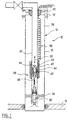
- FIG. 1 is shown, generally at 10, an installation for an oil well in which a well 12 extends between the surface 14 and a layer of oil-bearing rock 16.
- the well 12 has a casing 18 which makes the well tight in relation to to the rock layers crossed by the well.
- a production casing 20 between a well head, shown diagrammatically at 22, and a seal 24, more commonly known as a "packer” which is arranged, for example, about 100 m above the level of the petroleum rock 16.
- a sealed chamber 26 is defined between the outer wall of the casing 20 and the inner wall of the casing 18.
- the casing 20 comprises, at its lower end, a pumping assembly, generally represented at 28 which comprises a reciprocating pump 30 intended to be actuated in the direction of the arrow 32 by a linear electric motor 34 by l by means of a piston rod 36.
- the linear electric motor 34 is supplied from the surface 14 by an electric cable 38 placed in the chamber 26.
- the linear motor 34 comprises a stator 40 and a movable part 42 displaceable according to the effect of the magnetic field generated by the stator.
- the stator 40 is mounted outside the casing 20 inside the chamber 26.
- the casing 20, at least in the region 43 adjoining the linear motor 34, is formed of non-magnetic material, which, in a preferred example, is ceramic.
- the mobile part 42 is provided, at its upper end with a hooking head 44 which makes it possible to rise to the surface, for example by means of a cable, the mobile part 42 as well as the pump 30.
- the cooling of the motor is ensured by the extracted effluent which passes through the mechanical part of the motor, either by passing through the air gap between the mobile part and the stationary stator, or at the center of the mobile part, then hollowed out.
- the chamber 26 containing the electrical part can, in a preferred embodiment, receive a dielectric substance, a liquid or a gel, in order to further reinforce the durability of the installation.
- a gel also has the advantage of thermally insulating the tubing, which then receives all the heat dissipated in the cable 38 which runs along it and of which it serves as a radiator. This warm-up will ensure a better overall energy efficiency of the installation thanks to the heating of the flows.
- the pump 30 As shown in FIG. 1, it is preferable to place the pump 30 under the motor 34, which offers advantages for certain types of viscous or gaseous effluents in favor of the performance of the well. Indeed, the fact of placing the pump under the motor significantly reduces the pressure losses before the effluent enters the pump.
- the lubrication between the moving and fixed parts is done either dry with suitable materials (ceramic, zirconium, teflon, carbides or bronze), or by an effluent film put in place by hydrodynamic effect.
- suitable materials ceramic, zirconium, teflon, carbides or bronze
- a parallel lubrication system could also be implemented.
- the installation according to the invention avoids the electrical crossing of the seal or "packer" which was hitherto inevitable and constituted a source of the main electrical failures of the systems used until then.
- a second embodiment is shown in Figure 2 in which the elements common to the installation of Figure 1 bear the same reference numbers.
- a rotary motor generally represented at 46, is connected to a rotary pump of conventional construction, shown diagrammatically at 48, by a rod 50.
- the fixed part of the rotary motor 46, in particular the stator 52 is arranged outside the casing 20, only the movable part is located inside the casing in the corrosive and aggressive medium constituted by the hydrocarbons and effluents from the well.
- the movable part of the rotary motor comprises a rotor 54 disposed around a shaft 56 provided with a longitudinal passage 58.
- the section 60 of the casing 20 located between the coils 62 of the stator 52 and the rotor 54, is formed of a non-magnetic material so as not to disturb the magnetic field passing through it.
- the shaft 56 is mounted to rotate freely in the casing 20 by means of upper 64, central 66 and lower 68 bearings with an axial stop.
- the bearings 64, 66, 68 are each provided with a radial passage which communicates with the longitudinal passage 58 and which provides the lubrication of the bearings.
- the mobile part of the motor comprises, at its upper end, a hooking head 44 making it possible to raise the mobile part of the motor as well as the pump 48 to the surface. This operation is conventionally performed by cable from the surface.
- the installation according to the invention makes it possible to isolate the electrical part of the engines from the hydrocarbons or effluents passing inside the casing 20, hydrocarbons which constitute a corrosive medium.
- This type of installation considerably reduces the number of electrical failures while allowing easy replacement of the moving parts of the installation.
Landscapes
- Engineering & Computer Science (AREA)
- Geology (AREA)
- Life Sciences & Earth Sciences (AREA)
- Mining & Mineral Resources (AREA)
- Geochemistry & Mineralogy (AREA)
- Fluid Mechanics (AREA)
- Environmental & Geological Engineering (AREA)
- General Life Sciences & Earth Sciences (AREA)
- Physics & Mathematics (AREA)
- Mechanical Engineering (AREA)
- General Engineering & Computer Science (AREA)
- Structures Of Non-Positive Displacement Pumps (AREA)
- Drilling And Exploitation, And Mining Machines And Methods (AREA)
- Earth Drilling (AREA)
- Compressor (AREA)
- Lubrication Of Internal Combustion Engines (AREA)
- Connection Of Motors, Electrical Generators, Mechanical Devices, And The Like (AREA)
Abstract
Description
- La présente invention se rapporte à une installation pour puits pétrolier munie d'une électropompe en fond de puits.
- Dans certains puits pétroliers, l'écoulement naturel des hydrocarbures du fond à la surface s'avère insuffisant pour permettre ou maintenir une production commerciale. Ceci est dû soit à la viscosité importante des hydrocarbures, soit à une trop faible pression naturelle au fond du puits ou encore à une combinaison des deux. Afin de permettre la mise en production du puits à une échelle commerciale, on peut utiliser un système d'assistance ou système d'activation du puits. Par exemple, on peut disposer une pompe, à l'extrémité inférieure d'un tube de production situé dans le puits. Cette pompe peut être mue par un moteur électrique immergé au fond du puits qui est alimenté par un câble disposé dans l'espace annulaire entre le tubage et le cuvelage du puits.
- Quand on fait un bilan des sources de pannes sur les pompes électriques, ou électropompes, immergées de fond de puits qui nécessitent le retrait d'un tubage, on trouve dans l'ordre :
- les courts-circuits électriques (environ 80%),
- l'usure mécanique,
- la rupture mécanique.
- Certes, certains courts-circuits surviennent dès le premier démarrage et résultent d'une faute lors de l'installation qui demande beaucoup de soin et de savoir-faire.
- Mais la plupart des courts-circuits ont lieu en cours d'utilisation et résultent d'une dégradation progressive normale des barrières d'isolation électrique, puisque les pompes sont immergées dans l'effluent extrait de la roche pétrolifère.
- La gamme de puissance et la profondeur d'installation requièrent des voltages élevés, pouvant atteindre 1000 à 3000 volts pour minimiser les pertes dans les câbles. Mais ces tensions élevées rendent les installations vulnérables.
- L'altération des isolants solides résulte de phénomènes facilement compréhensibles :
- L'exploitation du puits engendre nécessairement des variations de pression et de température, dus aux arrêts et aux changements de régimes, dans les zones où se trouvent les équipements de pompage, créant des cycles de sollicitations mécaniques dans les matériaux constitutifs.
- Les variations de pression provoquent aussi des migrations répétées de gaz au sein des isolants, qui tendent à dégrader leur structure et leur performance.
- La présence d'hydrocarbures, d'aromatiques, de gaz acides et autres provoque des attaques chimiques diverses sur les différentes barrières d'isolation mécanique ou électrique, contribuant à leur dégradation dans le temps.
- Les variations de courant électrique (notamment les arrêts et démarrages du moteur) traversant les conducteurs électriques engendrent par effet Joule des variations de température importantes qui accélèrent le vieillissement des isolants électriques.
- Les voltages élevés évoqués ci-dessus génèrent des champs de sollicitations importants sur tous les isolants.
- Le deuxième facteur de coût d'utilisation des électropompes immergées de fond de puits est que pour réparer une panne, il faut remonter tout le câble électrique et le tubage auquel l'unité de fond est accrochée. En effet, les électropompes de fond de puits actuelles constituent des blocs tubulaires compacts assemblés en surface avant leur descente dans le puits. Ces sytèmes doivent, par conséquent, être remontés en totalité avec le tubage en cas de maintenance. Cette intervention nécessite un appareil de service onéreux à mobiliser, notamment sur des sites difficiles d'accès (isolé, en mer, sous-marin, urbain). Le délai d'attente et la durée d'intervention génèrent aussi des manques à produire importants. A tel point que ces systèmes ne peuvent s'envisager dans les cas les plus difficiles.
- L'ensemble de ces facteurs affecte dramatiquement le coût de ce mode de pompage et interdisent même économiquement le développement de certains champs pétroliers marginaux.
- Une installation de pompage aux tiges consiste en une pompe de fond volumétrique installée dans le tubage dont le piston est animé en translation depuis la surface par l'intermédiaire de tiges en acier ou en fibres de verre. En surface, le mouvement est donné au train de tige par une structure à balancier animé par un moteur électrique rotatif ou bien un vérin hydraulique.
- Le poids propre, l'inertie, le frottement et la fatigue mécanique des tiges limitent la capacité et la performance de pompage de ces systèmes. Ils sont peu adaptés aux puits éruptifs sur lesquels des organes de sécurité de fond sont requis, aux puits profonds ou aux débits élevés (supérieures à 200 m³/j de liquide).
- Le concept monobloc des électropompes de fond actuelles est intéressant dans le cas de puits où la manoeuvre de manutention est facile et peu onéreuse, cas des puits d'eau potable, des puits non éruptifs à terre ou peu profonds. Il n'est pas adapté aux puits pétroliers actuels et à venir. Ceux-ci sont de plus en plus profonds, inaccessibles, dangereux (car souvent éruptifs), et dotés d'équipements complexes et délicats à mettre en place. Il devient souhaitable de concentrer les faiblesses incontournables comme l'usure mécanique sur un module indépendant qui serait plus léger et moins coûteux à remonter et remplacer, avec un câble ou un treuil par exemple.
- Etant donné que la majorité des causes de panne provient du fait que la partie électrique est immergée dans un milieu hostile, il serait souhaitable de regrouper l'ensemble de la partie électrique dans une enceinte à l'abri de toute agression susceptible d'entraîner des pannes électriques. Ne resteraient en contact avec les effluents que les organes "mécaniques" ne pouvant être la cause ou la proie de courts-circuits électriques, et pouvant être indépendamment remontés et remplacés dans un but de maintenance, suite à une usure mécanique, ou de flexibilité, pour s'adapter par exemple à une évolution des effluents du puits ou des conditions d'exploitation.
- La présente invention a donc pour objet une installation pour puits pétrolier qui permet de séparer la partie électrique des parties mécaniques d'un groupe électropompe immergé dans le puits, de placer la partie électrique dans une enceinte à l'abri des agressions extérieures provenant notamment des effluents du fond de puits, et de regrouper les parties mécaniques afin de faciliter leur retrait.
- Pour ce faire, l'invention propose une installation pour puits pétrolier s'étendant de la surface vers une couche de roche pétrolifère comprenant un tubage disposé dans le puits et formant une voie d'écoulement vers la surface pour des hydrocarbures provenant de la couche de roche pétrolifère, un cuvelage délimitant la paroi du puits, et un joint disposé en fond de puits entre le tubage et le cuvelage de manière à former une chambre isolée des hydrocarbures, l'installation comprenant de plus, dans le puits, une pompe et un moteur électrique destiné à actionner la pompe caractérisé en ce que le stator du moteur électrique est disposé à l'extérieur du tubage, isolé par celui-ci des hydrocarbures s'écoulant à l'intérieur du tubage.
- Le moteur électrique peut être un moteur rotatif ou linéaire.
- Selon un mode de réalisation préférée, la pompe est placée en amont du moteur électrique.
- La présente invention présente l'avantage de créer une barrière d'étanchéité infranchissable par l'effluent entre la partie mobile centrale et les bobinages du stator. Actuellement dynamique, cette barrière est une technologie plus simple et plus fiable car il s'agit d'une barrière statique de type paroi, qui n'est plus traversée par une partie mobile (arbre ou tige) transmettant le mouvement à la partie mobile de la pompe.
- La partie mobile du moteur peut être mise en place et retirée indépendamment de la partie fixe, et en particulier des équipements électriques, et de plus grâce à une intervention légère au câble, ce qui facilite la maintenance mécanique et réduit les coûts d'exploitation.
- D'autres caractéristiques et avantages de la présente invention ressortiront à la lecture de la description suivante, donnée à titre explicatif mais non limitatif, faite en relation avec les dessins annexés sur lesquels :
- la figure 1 est une vue en coupe d'une installation pour puits pétrolier selon un premier aspect de l'invention ;
- la figure 2 est une vue en coupe d'une installation pour puits pétrolier selon un deuxième aspect de l'invention ; et
- la figure 2A est une vue en coupe, prise selon la ligne A-A de la figure 2.
- Sur la figure 1 est représentée, généralement en 10, une installation pour puits pétrolier dans laquelle un puits 12 s'étend entre la surface 14 et une couche de roche pétrolifère 16. Le puits 12 comporte un cuvelage 18 qui rend le puits étanche par rapport aux couches de roches traversées par le puits. A l'intérieur du puits s'étend un tubage de production 20, entre une tête de puits, représentée schématiquement en 22, et un joint 24, plus communément appelé "packer" qui est disposé, par exemple, à environ 100 m au-dessus du niveau de la roche pétrolifère 16. Une chambre 26 étanche est définie entre la paroi extérieure du tubage 20 et la paroi intérieure du cuvelage 18.
- Dans l'exemple illustré, le tubage 20 comporte, à son extrémité inférieure, un ensemble de pompage, représenté généralement en 28 qui comprend une pompe alternative 30 destinée à être actionnée dans le sens de la flèche 32 par un moteur électrique linéaire 34 par l'intermédiaire d'une tige de piston 36. Le moteur électrique linéaire 34 est alimenté à partir de la surface 14 par un câble électrique 38 disposé dans la chambre 26.
- Le moteur linéaire 34 comprend un stator 40 et une partie mobile 42 déplaçable selon l'effet du champ magnétique généré par le stator. Selon l'invention, le stator 40 est monté à l'extérieur du tubage 20 à l'intérieur de la chambre 26. Le tubage 20, au moins dans la région 43 avoisinant le moteur linéaire 34, est formé de matériau amagnétique, qui, dans un exemple préféré, est de la céramique. La partie mobile 42 est munie, à son extrémité supérieure d'une tête d'accrochage 44 qui permet de remonter à la surface, par exemple au moyen d'un câble, la partie mobile 42 ainsi que la pompe 30.
- Le refroidissement du moteur est assuré par l'effluent extrait qui traverse la partie mécanique du moteur, soit en passant dans l'entrefer entre la partie mobile et le stator immobile, soit au centre de la partie mobile, alors évidée.
- La chambre 26 contenant la partie électrique peut, dans un mode de réalisation préférée, recevoir une substance diélectrique, un liquide ou un gel, afin de renforcer encore la pérennité de l'installation. L'utilisation d'un gel présente aussi l'avantage d'isoler thermiquement le tubing, qui reçoit alors toute la chaleur dissipée dans le câble 38 qui le longe et dont il sert de radiateur. Cet échauffement assurera un meilleur rendement énergétique global de l'installation grâce à l'échauffement des écoulements.
- Comme représenté sur la figure 1, il est préférable de placer la pompe 30 sous le moteur 34, ce qui offre des avantages pour certains types d'effluents visqueux ou gazés au profit des performances du puits. En effet, le fait de placer la pompe sous le moteur réduit nettement les pertes de charge avant l'entrée de l'effluent dans la pompe.
- La lubrification entre les parties mobiles et fixes se fait soit à sec avec des matériaux appropriés (céramique, zirconium, téflon, carbures ou bronze), soit par un film d'effluent mis en place par effet hydrodynamique. Un système parallèle de lubrification pourrait aussi être mis en place.
- L'installation selon l'invention évite la traversée électrique du joint ou "packer" qui était jusqu'à présent inévitable et constituait une source des principales pannes électriques des systèmes utilisés jusqu'alors.
- Un deuxième mode de réalisation est représenté sur la figure 2 dans laquelle les éléments communs à l'installation de la figure 1 portent les mêmes chiffres de référence. Un moteur rotatif, représenté généralement en 46, est relié à une pompe rotative de construction classique, représentée schématiquement en 48, par une tige 50. De manière analogue à l'installation de la figure 1, la partie fixe du moteur rotatif 46, notamment le stator 52, est disposée à l'extérieur du tubage 20, seule la partie mobile se trouve à l'intérieur du tubage dans le milieu corrosif et agressif que constituent les hydrocarbures et les effluents du puits. La partie mobile du moteur rotatif comprend un rotor 54 disposé autour d'un arbre 56 muni d'un passage longitudinal 58. La section 60 du tubage 20 se trouvant entre les bobinages 62 du stator 52 et le rotor 54, est formée d'un matériau amagnétique de sorte à ne pas perturber le champ magnétique qui la traverse.
- L'arbre 56 est monté libre en rotation dans le tubage 20 par l'intermédiaire de paliers supérieur 64, central 66 et inférieur 68 à butée axiale. Les paliers 64, 66, 68 sont munis chacun d'un passage radial qui communique avec le passage longitudinal 58 et qui assure la lubrification des paliers. Comme dans le mode de réalisation de la figure 1, la partie mobile du moteur comporte, à son extrémité supérieure, une tête d'accrochage 44 permettant de remonter à la surface la partie mobile du moteur ainsi que la pompe 48. Cette opération s'effectue de manière classique par câble depuis la surface.
- Ainsi l'installation selon l'invention permet d'isoler la partie électrique des moteurs des hydrocarbures ou des effluents passant à l'intérieur du tubage 20, hydrocarbures qui constituent un milieu corrosif. Ce type d'installation permet de réduire considérablement le nombre de pannes électriques tout en permettant un remplacement facile des parties mobiles de l'installation.
Claims (6)
- Installation pour puits pétrolier s'étendant de la surface (14) vers une couche de roche pétrolifère (16) comprenant un tubage (20) disposé dans le puits et formant une voie d'écoulement vers la surface pour des hydrocarbures provenant de la couche de roche pétrolifère, un cuvelage (18) délimitant la paroi du puits, et un joint (24) disposé en fond de puits entre le tubage (20) et le cuvelage (18) de manière à former une chambre (26) isolée des hydrocarbures, l'installation comprenant de plus, dans le puits, une pompe (30, 48) et un moteur électrique (34, 46) destiné à actionner la pompe, caractérisé en ce que le stator (40, 52) et le câble du moteur électrique (38) sont disposés dans la chambre (26).
- Installation selon la revendication 1 caractérisée en ce que le tubage (20) est formé de matériau amagnétique sur au moins la longueur où le tubage traverse le moteur électrique (34, 46).
- Installation selon la revendication 1 ou 2 caractérisée en ce que le moteur électrique est du type linéaire (34).
- Installation selon la revendication 1 ou 2 caractérisée en ce que le moteur électrique est du type rotatif (46).
- Installation selon l'une des revendications 1 à 4 caractérisée en ce que la pompe (30, 48) est disposée en amont du moteur électrique (34, 46).
- Installation selon l'une des revendications 1 à 5 caractérisée en ce que la partie mobile du moteur électrique (34, 46) comporte une tête d'accrochage (44) destinée à permettre de remonter à la surface ladite partie mobile et la pompe (30, 48).
Applications Claiming Priority (2)
| Application Number | Priority Date | Filing Date | Title |
|---|---|---|---|
| FR9411750A FR2725238B1 (fr) | 1994-09-30 | 1994-09-30 | Installation pour puits petrolier munie d'une electropompe en fond de puits |
| FR9411750 | 1994-09-30 |
Publications (2)
| Publication Number | Publication Date |
|---|---|
| EP0704599A1 true EP0704599A1 (fr) | 1996-04-03 |
| EP0704599B1 EP0704599B1 (fr) | 1998-05-20 |
Family
ID=9467481
Family Applications (1)
| Application Number | Title | Priority Date | Filing Date |
|---|---|---|---|
| EP95402176A Expired - Lifetime EP0704599B1 (fr) | 1994-09-30 | 1995-09-28 | Installation pour puits pétrolier munie d'une électropompe en fond de puits |
Country Status (8)
| Country | Link |
|---|---|
| US (1) | US5620048A (fr) |
| EP (1) | EP0704599B1 (fr) |
| AT (1) | ATE166425T1 (fr) |
| CA (1) | CA2159556A1 (fr) |
| DE (1) | DE69502563T2 (fr) |
| FR (1) | FR2725238B1 (fr) |
| NO (1) | NO953864L (fr) |
| OA (1) | OA10232A (fr) |
Cited By (4)
| Publication number | Priority date | Publication date | Assignee | Title |
|---|---|---|---|---|
| WO1996036790A1 (fr) * | 1995-05-17 | 1996-11-21 | Raymond Lucet | Dispositif pour l'alimentation electrique d'une pompe immergee suspendue a un tuyau, en particulier un tuyau souple |
| WO1998022692A1 (fr) * | 1996-11-21 | 1998-05-28 | Baker Hughes Incorporated | Pompe de puits recuperable a tube en spirale/cable electrique |
| EP0854266A2 (fr) * | 1997-01-17 | 1998-07-22 | Camco International Inc. | Procédé et dispositif pour récupérer une pompe rotative d'un puits |
| WO2001002699A1 (fr) * | 1999-07-02 | 2001-01-11 | Shell Internationale Research Maatschappij B.V. | Procede permettant de deployer un systeme de transduction fluidique a alimentation electrique dans un puits |
Families Citing this family (60)
| Publication number | Priority date | Publication date | Assignee | Title |
|---|---|---|---|---|
| FR2746858B1 (fr) * | 1996-03-29 | 2001-09-21 | Elf Aquitaine | Electropompe a moteur lineaire |
| US5951262A (en) * | 1997-04-18 | 1999-09-14 | Centriflow Llc | Mechanism for providing motive force and for pumping applications |
| WO1998048167A2 (fr) * | 1997-04-18 | 1998-10-29 | Centriflow Llc | Mecanisme permettant de produire une force motrice pour des applications de pompage |
| US6131660A (en) * | 1997-09-23 | 2000-10-17 | Texaco Inc. | Dual injection and lifting system using rod pump and an electric submersible pump (ESP) |
| US6419011B1 (en) * | 1997-09-05 | 2002-07-16 | Bei Technology | Annular shaped interrupted solenoid activator and pump for borehole subsea use (BEI-0002) |
| US6056511A (en) * | 1998-01-13 | 2000-05-02 | Camco International, Inc. | Connection module for a submergible pumping system and method for pumping fluids using such a module |
| US6206093B1 (en) | 1999-02-24 | 2001-03-27 | Camco International Inc. | System for pumping viscous fluid from a well |
| US6231318B1 (en) | 1999-03-29 | 2001-05-15 | Walbro Corporation | In-take fuel pump reservoir |
| US6227819B1 (en) | 1999-03-29 | 2001-05-08 | Walbro Corporation | Fuel pumping assembly |
| US6318467B1 (en) | 1999-12-01 | 2001-11-20 | Camco International, Inc. | System and method for pumping and heating viscous fluids in a wellbore |
| US6352455B1 (en) | 2000-06-22 | 2002-03-05 | Peter A. Guagliano | Marine propulsion device |
| US6619388B2 (en) * | 2001-02-15 | 2003-09-16 | Halliburton Energy Services, Inc. | Fail safe surface controlled subsurface safety valve for use in a well |
| US7299873B2 (en) * | 2001-03-12 | 2007-11-27 | Centriflow Llc | Method for pumping fluids |
| CN1281847C (zh) * | 2001-03-12 | 2006-10-25 | 中心流动有限公司 | 一种泵送流体的方法 |
| US6536526B2 (en) | 2001-04-02 | 2003-03-25 | Baker Hughes Incorporated | Method for decreasing heat transfer from production tubing |
| US6817409B2 (en) * | 2001-06-13 | 2004-11-16 | Weatherford/Lamb, Inc. | Double-acting reciprocating downhole pump |
| WO2003001029A1 (fr) | 2001-06-26 | 2003-01-03 | Weatherford/Lamb, Inc. | Pompe electrique destinee a etre utilisee dans la completion d'un puits |
| US6988556B2 (en) * | 2002-02-19 | 2006-01-24 | Halliburton Energy Services, Inc. | Deep set safety valve |
| GB2399360B (en) | 2003-03-10 | 2005-05-11 | Fmc Technologies | Downhole reversible pump for hydrocarbon recovery |
| US7445531B1 (en) | 2003-08-25 | 2008-11-04 | Ross Anthony C | System and related methods for marine transportation |
| NO323081B1 (no) * | 2005-05-27 | 2006-12-27 | Ziebel As | Anordning og fremgangsmate for selektiv framdrift av et bronnintervensjonsverktoy i en rorstreng |
| CN100373054C (zh) * | 2006-03-14 | 2008-03-05 | 赵锡寰 | 悬吊式电潜螺杆泵的导流导电系统 |
| US7640989B2 (en) * | 2006-08-31 | 2010-01-05 | Halliburton Energy Services, Inc. | Electrically operated well tools |
| US20080080991A1 (en) * | 2006-09-28 | 2008-04-03 | Michael Andrew Yuratich | Electrical submersible pump |
| US8919730B2 (en) | 2006-12-29 | 2014-12-30 | Halliburton Energy Services, Inc. | Magnetically coupled safety valve with satellite inner magnets |
| US8038120B2 (en) | 2006-12-29 | 2011-10-18 | Halliburton Energy Services, Inc. | Magnetically coupled safety valve with satellite outer magnets |
| US20080264625A1 (en) * | 2007-04-26 | 2008-10-30 | Brian Ochoa | Linear electric motor for an oilfield pump |
| US7610964B2 (en) * | 2008-01-18 | 2009-11-03 | Baker Hughes Incorporated | Positive displacement pump |
| US8176975B2 (en) * | 2008-04-07 | 2012-05-15 | Baker Hughes Incorporated | Tubing pressure insensitive actuator system and method |
| US8398050B2 (en) * | 2009-08-13 | 2013-03-19 | Baker Hughes Incorporated | Hold open configuration for safety valve and method |
| US8662187B2 (en) * | 2009-08-13 | 2014-03-04 | Baker Hughes Incorporated | Permanent magnet linear motor actuated safety valve and method |
| US8393386B2 (en) * | 2009-11-23 | 2013-03-12 | Baker Hughes Incorporated | Subsurface safety valve and method of actuation |
| US8267167B2 (en) * | 2009-11-23 | 2012-09-18 | Baker Hughes Incorporated | Subsurface safety valve and method of actuation |
| US8573304B2 (en) | 2010-11-22 | 2013-11-05 | Halliburton Energy Services, Inc. | Eccentric safety valve |
| US8511374B2 (en) | 2011-08-02 | 2013-08-20 | Halliburton Energy Services, Inc. | Electrically actuated insert safety valve |
| US8490687B2 (en) | 2011-08-02 | 2013-07-23 | Halliburton Energy Services, Inc. | Safety valve with provisions for powering an insert safety valve |
| GB2505961A (en) * | 2012-09-18 | 2014-03-19 | Statoil Petroleum As | Pump for lifting fluid from a wellbore |
| WO2016032690A1 (fr) | 2014-08-29 | 2016-03-03 | Moog Inc. | Moteur linéaire pour le pompage |
| US10302089B2 (en) | 2015-04-21 | 2019-05-28 | Baker Hughes, A Ge Company, Llc | Circulation pump for cooling mechanical face seal of submersible well pump assembly |
| US10989027B2 (en) * | 2018-07-27 | 2021-04-27 | Upwing Energy, LLC | Artificial lift |
| US10787873B2 (en) | 2018-07-27 | 2020-09-29 | Upwing Energy, LLC | Recirculation isolator for artificial lift and method of use |
| US10370947B1 (en) | 2018-07-27 | 2019-08-06 | Upwing Energy, LLC | Artificial lift |
| US10280721B1 (en) * | 2018-07-27 | 2019-05-07 | Upwing Energy, LLC | Artificial lift |
| US10253606B1 (en) | 2018-07-27 | 2019-04-09 | Upwing Energy, LLC | Artificial lift |
| US10914149B2 (en) | 2018-08-29 | 2021-02-09 | Upwing Energy, LLC | Artificial lift |
| US11686161B2 (en) | 2018-12-28 | 2023-06-27 | Upwing Energy, Inc. | System and method of transferring power within a wellbore |
| US10890056B2 (en) * | 2019-01-03 | 2021-01-12 | Upwing Energy, LLC | Downhole-type tool for artificial lift |
| US11125059B2 (en) * | 2019-01-03 | 2021-09-21 | Upwing Energy, LLC | Downhole-type tool for artificial lift |
| US11326607B2 (en) | 2019-02-05 | 2022-05-10 | Saudi Arabian Oil Company | Balancing axial thrust in submersible well pumps |
| US10844701B2 (en) * | 2019-02-05 | 2020-11-24 | Saudi Arabian Oil Company | Balancing axial thrust in submersible well pumps |
| CA3151074C (fr) * | 2019-10-25 | 2023-10-10 | Robert Charles DE LONG | Elimination de cire dans un tube de production |
| US11371326B2 (en) | 2020-06-01 | 2022-06-28 | Saudi Arabian Oil Company | Downhole pump with switched reluctance motor |
| US11499563B2 (en) | 2020-08-24 | 2022-11-15 | Saudi Arabian Oil Company | Self-balancing thrust disk |
| US11920469B2 (en) | 2020-09-08 | 2024-03-05 | Saudi Arabian Oil Company | Determining fluid parameters |
| US11644351B2 (en) | 2021-03-19 | 2023-05-09 | Saudi Arabian Oil Company | Multiphase flow and salinity meter with dual opposite handed helical resonators |
| US11591899B2 (en) | 2021-04-05 | 2023-02-28 | Saudi Arabian Oil Company | Wellbore density meter using a rotor and diffuser |
| US11913464B2 (en) | 2021-04-15 | 2024-02-27 | Saudi Arabian Oil Company | Lubricating an electric submersible pump |
| US11994016B2 (en) | 2021-12-09 | 2024-05-28 | Saudi Arabian Oil Company | Downhole phase separation in deviated wells |
| US12012550B2 (en) | 2021-12-13 | 2024-06-18 | Saudi Arabian Oil Company | Attenuated acid formulations for acid stimulation |
| US12085687B2 (en) | 2022-01-10 | 2024-09-10 | Saudi Arabian Oil Company | Model-constrained multi-phase virtual flow metering and forecasting with machine learning |
Citations (7)
| Publication number | Priority date | Publication date | Assignee | Title |
|---|---|---|---|---|
| US1840994A (en) * | 1930-01-20 | 1932-01-12 | Irwin B Winsor | Electromagnetic pump |
| EP0023126A1 (fr) * | 1979-07-18 | 1981-01-28 | The British Petroleum Company p.l.c. | Pompe de puits électrique |
| US4266607A (en) * | 1980-04-07 | 1981-05-12 | Mobil Oil Corporation | Method for protecting a carbon dioxide production well from corrosion |
| US4538970A (en) * | 1983-10-17 | 1985-09-03 | Rabson Thomas A | Downstroke lift pump for wells |
| US4687054A (en) * | 1985-03-21 | 1987-08-18 | Russell George W | Linear electric motor for downhole use |
| US4928771A (en) * | 1989-07-25 | 1990-05-29 | Baker Hughes Incorporated | Cable suspended pumping system |
| GB2275069A (en) * | 1993-02-03 | 1994-08-17 | Baker Hughes Ltd | Down hole installations |
Family Cites Families (12)
| Publication number | Priority date | Publication date | Assignee | Title |
|---|---|---|---|---|
| GB448449A (en) * | 1934-12-06 | 1936-06-08 | Electromersible Motors & Pumps | Improvements in or relating to submersible electric motor pumps |
| US2739650A (en) * | 1951-09-19 | 1956-03-27 | Perfect Circle Corp | Pumping apparatus |
| US2725824A (en) * | 1954-11-24 | 1955-12-06 | Reda Pump Company | Explosion-proof submergible electric motor and pump assembly |
| JPS53115902A (en) * | 1977-03-19 | 1978-10-09 | Toshiba Corp | Verylow temperature fluid pump |
| GB2112872A (en) * | 1981-12-10 | 1983-07-27 | British Petroleum Co Plc | Pumping apparatus for installation in wells |
| US4562385A (en) * | 1983-10-17 | 1985-12-31 | Rabson Thomas A | Periodic reciprocating motor |
| US4548552A (en) * | 1984-02-17 | 1985-10-22 | Holm Daniel R | Dual valve well pump installation |
| US4815949A (en) * | 1985-06-24 | 1989-03-28 | Rabson Thomas A | In-well submersible motor with stacked component stator |
| US4768595A (en) * | 1986-04-07 | 1988-09-06 | Marathon Oil Company | Oil recovery apparatus using an electromagnetic pump drive |
| US5049046A (en) * | 1990-01-10 | 1991-09-17 | Escue Research And Development Company | Pump control system for a downhole motor-pump assembly and method of using same |
| US5193985A (en) * | 1990-01-10 | 1993-03-16 | Uniflo Oilcorp, Ltd. | Pump control system for a downhole motor-pump assembly and method of using same |
| US5482117A (en) * | 1994-12-13 | 1996-01-09 | Atlantic Richfield Company | Gas-liquid separator for well pumps |
-
1994
- 1994-09-30 FR FR9411750A patent/FR2725238B1/fr not_active Expired - Fee Related
-
1995
- 1995-09-28 AT AT95402176T patent/ATE166425T1/de not_active IP Right Cessation
- 1995-09-28 DE DE69502563T patent/DE69502563T2/de not_active Expired - Fee Related
- 1995-09-28 EP EP95402176A patent/EP0704599B1/fr not_active Expired - Lifetime
- 1995-09-29 US US08/536,790 patent/US5620048A/en not_active Expired - Fee Related
- 1995-09-29 CA CA002159556A patent/CA2159556A1/fr not_active Abandoned
- 1995-09-29 OA OA60716A patent/OA10232A/fr unknown
- 1995-09-29 NO NO953864A patent/NO953864L/no unknown
Patent Citations (7)
| Publication number | Priority date | Publication date | Assignee | Title |
|---|---|---|---|---|
| US1840994A (en) * | 1930-01-20 | 1932-01-12 | Irwin B Winsor | Electromagnetic pump |
| EP0023126A1 (fr) * | 1979-07-18 | 1981-01-28 | The British Petroleum Company p.l.c. | Pompe de puits électrique |
| US4266607A (en) * | 1980-04-07 | 1981-05-12 | Mobil Oil Corporation | Method for protecting a carbon dioxide production well from corrosion |
| US4538970A (en) * | 1983-10-17 | 1985-09-03 | Rabson Thomas A | Downstroke lift pump for wells |
| US4687054A (en) * | 1985-03-21 | 1987-08-18 | Russell George W | Linear electric motor for downhole use |
| US4928771A (en) * | 1989-07-25 | 1990-05-29 | Baker Hughes Incorporated | Cable suspended pumping system |
| GB2275069A (en) * | 1993-02-03 | 1994-08-17 | Baker Hughes Ltd | Down hole installations |
Cited By (7)
| Publication number | Priority date | Publication date | Assignee | Title |
|---|---|---|---|---|
| WO1996036790A1 (fr) * | 1995-05-17 | 1996-11-21 | Raymond Lucet | Dispositif pour l'alimentation electrique d'une pompe immergee suspendue a un tuyau, en particulier un tuyau souple |
| WO1998022692A1 (fr) * | 1996-11-21 | 1998-05-28 | Baker Hughes Incorporated | Pompe de puits recuperable a tube en spirale/cable electrique |
| GB2325483A (en) * | 1996-11-21 | 1998-11-25 | Baker Hughes Inc | Wireline/coiled tubing retrievable well pump |
| GB2325483B (en) * | 1996-11-21 | 2001-03-07 | Baker Hughes Inc | Wireline/coiled tubing retrievable well pump |
| EP0854266A2 (fr) * | 1997-01-17 | 1998-07-22 | Camco International Inc. | Procédé et dispositif pour récupérer une pompe rotative d'un puits |
| EP0854266A3 (fr) * | 1997-01-17 | 1999-04-28 | Camco International Inc. | Procédé et dispositif pour récupérer une pompe rotative d'un puits |
| WO2001002699A1 (fr) * | 1999-07-02 | 2001-01-11 | Shell Internationale Research Maatschappij B.V. | Procede permettant de deployer un systeme de transduction fluidique a alimentation electrique dans un puits |
Also Published As
| Publication number | Publication date |
|---|---|
| OA10232A (fr) | 1997-09-19 |
| EP0704599B1 (fr) | 1998-05-20 |
| DE69502563D1 (de) | 1998-06-25 |
| FR2725238B1 (fr) | 1996-11-22 |
| NO953864D0 (no) | 1995-09-29 |
| US5620048A (en) | 1997-04-15 |
| NO953864L (no) | 1996-04-01 |
| FR2725238A1 (fr) | 1996-04-05 |
| CA2159556A1 (fr) | 1996-03-31 |
| DE69502563T2 (de) | 1999-01-14 |
| ATE166425T1 (de) | 1998-06-15 |
Similar Documents
| Publication | Publication Date | Title |
|---|---|---|
| EP0704599B1 (fr) | Installation pour puits pétrolier munie d'une électropompe en fond de puits | |
| FR2746858A1 (fr) | Electropompe a moteur lineaire | |
| EP0793330A1 (fr) | Générateur d'énergie électrique en ligne autonome | |
| RU2498113C2 (ru) | Подводный добычной агрегат | |
| WO2001018942A1 (fr) | Moteur electrique a courant alternatif | |
| FR2632787A1 (fr) | Moteur de pompe electrique submersible rempli d'huile | |
| EP3455536A1 (fr) | Dispositif chauffant pour le transport d'un mélange multiphasique d'hydrocarbures et procédé associé | |
| FR2867627A1 (fr) | Appareil et methode de production d'energie electrique dans un sondage | |
| EP1306560A1 (fr) | Actionneur électrohydraulique autonome | |
| US20090047156A1 (en) | Insulated bearings for downhole motors | |
| US5336064A (en) | Electric motor driven pump | |
| US8851864B2 (en) | Attenuating vibration in a submersible pump | |
| US20220065081A1 (en) | Submersible canned motor pump | |
| BE539440A (fr) | ||
| CA2911198C (fr) | Conduit de transport d`un fluide chauffe electriquement | |
| FR2476772A1 (fr) | Groupe moto-pompe protege contre l'usure des paliers | |
| NO342118B1 (en) | Apparatus and method of pumping well fluid from a well | |
| US3854064A (en) | Mechanical seal isolator | |
| CA2154994C (fr) | Installation pour puits petrolier | |
| EP0065922A1 (fr) | Pompe primaire d'un réacteur nucléaire à eau sous pression comportant un dispositif d'étanchéité de son arbre d'entrainement | |
| FR2826402A1 (fr) | Support pour moyen de mesure dans un puits de production d'hydrocarbures | |
| EP3835641A1 (fr) | Installation sous-marine de chauffage d'un effluent diphasique liquide/gaz circulant à l'intérieur d'une enveloppe sous-marine | |
| WO2023031566A1 (fr) | Groupe motopompe electrique, procede de fabrication et procede d'installation d'un tel groupe motopompe | |
| Miwa et al. | ESP performance in Mubarraz Field | |
| RU2210159C2 (ru) | Устройство для гидравлической защиты погружного маслонаполненного электродвигателя |
Legal Events
| Date | Code | Title | Description |
|---|---|---|---|
| PUAI | Public reference made under article 153(3) epc to a published international application that has entered the european phase |
Free format text: ORIGINAL CODE: 0009012 |
|
| 17P | Request for examination filed |
Effective date: 19951004 |
|
| AK | Designated contracting states |
Kind code of ref document: A1 Designated state(s): AT DE FR GB IT NL |
|
| 17Q | First examination report despatched |
Effective date: 19961129 |
|
| GRAG | Despatch of communication of intention to grant |
Free format text: ORIGINAL CODE: EPIDOS AGRA |
|
| GRAG | Despatch of communication of intention to grant |
Free format text: ORIGINAL CODE: EPIDOS AGRA |
|
| GRAH | Despatch of communication of intention to grant a patent |
Free format text: ORIGINAL CODE: EPIDOS IGRA |
|
| GRAH | Despatch of communication of intention to grant a patent |
Free format text: ORIGINAL CODE: EPIDOS IGRA |
|
| GRAA | (expected) grant |
Free format text: ORIGINAL CODE: 0009210 |
|
| AK | Designated contracting states |
Kind code of ref document: B1 Designated state(s): AT DE FR GB IT NL |
|
| REF | Corresponds to: |
Ref document number: 166425 Country of ref document: AT Date of ref document: 19980615 Kind code of ref document: T |
|
| REF | Corresponds to: |
Ref document number: 69502563 Country of ref document: DE Date of ref document: 19980625 |
|
| ITF | It: translation for a ep patent filed | ||
| GBT | Gb: translation of ep patent filed (gb section 77(6)(a)/1977) |
Effective date: 19980819 |
|
| PLBE | No opposition filed within time limit |
Free format text: ORIGINAL CODE: 0009261 |
|
| STAA | Information on the status of an ep patent application or granted ep patent |
Free format text: STATUS: NO OPPOSITION FILED WITHIN TIME LIMIT |
|
| 26N | No opposition filed | ||
| PGFP | Annual fee paid to national office [announced via postgrant information from national office to epo] |
Ref country code: AT Payment date: 19990827 Year of fee payment: 5 |
|
| PGFP | Annual fee paid to national office [announced via postgrant information from national office to epo] |
Ref country code: NL Payment date: 19990831 Year of fee payment: 5 Ref country code: GB Payment date: 19990831 Year of fee payment: 5 |
|
| PGFP | Annual fee paid to national office [announced via postgrant information from national office to epo] |
Ref country code: DE Payment date: 19990903 Year of fee payment: 5 |
|
| PGFP | Annual fee paid to national office [announced via postgrant information from national office to epo] |
Ref country code: FR Payment date: 19990929 Year of fee payment: 5 |
|
| PG25 | Lapsed in a contracting state [announced via postgrant information from national office to epo] |
Ref country code: GB Free format text: LAPSE BECAUSE OF NON-PAYMENT OF DUE FEES Effective date: 20000928 Ref country code: AT Free format text: LAPSE BECAUSE OF NON-PAYMENT OF DUE FEES Effective date: 20000928 |
|
| PG25 | Lapsed in a contracting state [announced via postgrant information from national office to epo] |
Ref country code: NL Free format text: LAPSE BECAUSE OF NON-PAYMENT OF DUE FEES Effective date: 20010401 |
|
| GBPC | Gb: european patent ceased through non-payment of renewal fee |
Effective date: 20000928 |
|
| PG25 | Lapsed in a contracting state [announced via postgrant information from national office to epo] |
Ref country code: FR Free format text: LAPSE BECAUSE OF NON-PAYMENT OF DUE FEES Effective date: 20010531 |
|
| NLV4 | Nl: lapsed or anulled due to non-payment of the annual fee |
Effective date: 20010401 |
|
| PG25 | Lapsed in a contracting state [announced via postgrant information from national office to epo] |
Ref country code: DE Free format text: LAPSE BECAUSE OF NON-PAYMENT OF DUE FEES Effective date: 20010601 |
|
| REG | Reference to a national code |
Ref country code: FR Ref legal event code: ST |
|
| PG25 | Lapsed in a contracting state [announced via postgrant information from national office to epo] |
Ref country code: IT Free format text: LAPSE BECAUSE OF NON-PAYMENT OF DUE FEES;WARNING: LAPSES OF ITALIAN PATENTS WITH EFFECTIVE DATE BEFORE 2007 MAY HAVE OCCURRED AT ANY TIME BEFORE 2007. THE CORRECT EFFECTIVE DATE MAY BE DIFFERENT FROM THE ONE RECORDED. Effective date: 20050928 |