EP0704327A2 - Apparatus and method for controlling damping force characteristic of vehicular suspension system - Google Patents
Apparatus and method for controlling damping force characteristic of vehicular suspension system Download PDFInfo
- Publication number
- EP0704327A2 EP0704327A2 EP95115432A EP95115432A EP0704327A2 EP 0704327 A2 EP0704327 A2 EP 0704327A2 EP 95115432 A EP95115432 A EP 95115432A EP 95115432 A EP95115432 A EP 95115432A EP 0704327 A2 EP0704327 A2 EP 0704327A2
- Authority
- EP
- European Patent Office
- Prior art keywords
- damping force
- sprung mass
- denotes
- force characteristic
- mass
- Prior art date
- Legal status (The legal status is an assumption and is not a legal conclusion. Google has not performed a legal analysis and makes no representation as to the accuracy of the status listed.)
- Withdrawn
Links
Images


Classifications
-
- B—PERFORMING OPERATIONS; TRANSPORTING
- B60—VEHICLES IN GENERAL
- B60G—VEHICLE SUSPENSION ARRANGEMENTS
- B60G17/00—Resilient suspensions having means for adjusting the spring or vibration-damper characteristics, for regulating the distance between a supporting surface and a sprung part of vehicle or for locking suspension during use to meet varying vehicular or surface conditions, e.g. due to speed or load
- B60G17/015—Resilient suspensions having means for adjusting the spring or vibration-damper characteristics, for regulating the distance between a supporting surface and a sprung part of vehicle or for locking suspension during use to meet varying vehicular or surface conditions, e.g. due to speed or load the regulating means comprising electric or electronic elements
- B60G17/018—Resilient suspensions having means for adjusting the spring or vibration-damper characteristics, for regulating the distance between a supporting surface and a sprung part of vehicle or for locking suspension during use to meet varying vehicular or surface conditions, e.g. due to speed or load the regulating means comprising electric or electronic elements characterised by the use of a specific signal treatment or control method
-
- B—PERFORMING OPERATIONS; TRANSPORTING
- B60—VEHICLES IN GENERAL
- B60G—VEHICLE SUSPENSION ARRANGEMENTS
- B60G2202/00—Indexing codes relating to the type of spring, damper or actuator
- B60G2202/40—Type of actuator
- B60G2202/42—Electric actuator
-
- B—PERFORMING OPERATIONS; TRANSPORTING
- B60—VEHICLES IN GENERAL
- B60G—VEHICLE SUSPENSION ARRANGEMENTS
- B60G2400/00—Indexing codes relating to detected, measured or calculated conditions or factors
- B60G2400/10—Acceleration; Deceleration
- B60G2400/102—Acceleration; Deceleration vertical
-
- B—PERFORMING OPERATIONS; TRANSPORTING
- B60—VEHICLES IN GENERAL
- B60G—VEHICLE SUSPENSION ARRANGEMENTS
- B60G2400/00—Indexing codes relating to detected, measured or calculated conditions or factors
- B60G2400/20—Speed
- B60G2400/204—Vehicle speed
-
- B—PERFORMING OPERATIONS; TRANSPORTING
- B60—VEHICLES IN GENERAL
- B60G—VEHICLE SUSPENSION ARRANGEMENTS
- B60G2400/00—Indexing codes relating to detected, measured or calculated conditions or factors
- B60G2400/20—Speed
- B60G2400/206—Body oscillation speed; Body vibration frequency
-
- B—PERFORMING OPERATIONS; TRANSPORTING
- B60—VEHICLES IN GENERAL
- B60G—VEHICLE SUSPENSION ARRANGEMENTS
- B60G2400/00—Indexing codes relating to detected, measured or calculated conditions or factors
- B60G2400/25—Stroke; Height; Displacement
-
- B—PERFORMING OPERATIONS; TRANSPORTING
- B60—VEHICLES IN GENERAL
- B60G—VEHICLE SUSPENSION ARRANGEMENTS
- B60G2400/00—Indexing codes relating to detected, measured or calculated conditions or factors
- B60G2400/60—Load
-
- B—PERFORMING OPERATIONS; TRANSPORTING
- B60—VEHICLES IN GENERAL
- B60G—VEHICLE SUSPENSION ARRANGEMENTS
- B60G2400/00—Indexing codes relating to detected, measured or calculated conditions or factors
- B60G2400/90—Other conditions or factors
- B60G2400/91—Frequency
-
- B—PERFORMING OPERATIONS; TRANSPORTING
- B60—VEHICLES IN GENERAL
- B60G—VEHICLE SUSPENSION ARRANGEMENTS
- B60G2500/00—Indexing codes relating to the regulated action or device
- B60G2500/10—Damping action or damper
-
- B—PERFORMING OPERATIONS; TRANSPORTING
- B60—VEHICLES IN GENERAL
- B60G—VEHICLE SUSPENSION ARRANGEMENTS
- B60G2600/00—Indexing codes relating to particular elements, systems or processes used on suspension systems or suspension control systems
- B60G2600/18—Automatic control means
- B60G2600/184—Semi-Active control means
-
- B—PERFORMING OPERATIONS; TRANSPORTING
- B60—VEHICLES IN GENERAL
- B60G—VEHICLE SUSPENSION ARRANGEMENTS
- B60G2600/00—Indexing codes relating to particular elements, systems or processes used on suspension systems or suspension control systems
- B60G2600/76—Digital systems
-
- B—PERFORMING OPERATIONS; TRANSPORTING
- B60—VEHICLES IN GENERAL
- B60G—VEHICLE SUSPENSION ARRANGEMENTS
- B60G2800/00—Indexing codes relating to the type of movement or to the condition of the vehicle and to the end result to be achieved by the control action
- B60G2800/01—Attitude or posture control
- B60G2800/012—Rolling condition
-
- B—PERFORMING OPERATIONS; TRANSPORTING
- B60—VEHICLES IN GENERAL
- B60G—VEHICLE SUSPENSION ARRANGEMENTS
- B60G2800/00—Indexing codes relating to the type of movement or to the condition of the vehicle and to the end result to be achieved by the control action
- B60G2800/24—Steering, cornering
-
- B—PERFORMING OPERATIONS; TRANSPORTING
- B60—VEHICLES IN GENERAL
- B60G—VEHICLE SUSPENSION ARRANGEMENTS
- B60G2800/00—Indexing codes relating to the type of movement or to the condition of the vehicle and to the end result to be achieved by the control action
- B60G2800/90—System Controller type
- B60G2800/91—Suspension Control
- B60G2800/912—Attitude Control; levelling control
Definitions
- the present invention relates to apparatus and method for optimally controlling a damping force characteristic of a vehicular suspension system of an automotive vehicle.
- a Japanese Patent Application First Publication No. Showa 61-163011 exemplifies a first previously proposed suspension system damping force characteristic controlling apparatus, the suspension system having a plurality of shock absorbers.
- a sprung mass vertical velocity indicative signal and a relative velocity indicative signal between a sprung mass of a vehicle body and unsprung mass of a corresponding road wheel, the sprung mass and unsprung mass being located at a position adjacent to each shock absorber, are detected and outputted.
- the damping force characteristic of the corresponding one of the shock absorbers is set to a hard characteristic. If either one of the sprung mass vertical velocity signal and the unsprung mass vertical velocity signal is not coincident with the other of both of velocity signals, the damping force characteristic of the corresponding one of the shock absorbers is set to a soft characteristic. In this way, the damping force characteristic controls based on a Sky Hook theorem (theory) are carried out individually for the respective shock absorbers and independently of each other.
- a Japanese Patent Application First Publication No. Heisei 4-63712 exemplifies a second previously proposed suspension system damping force characteristic controlling apparatus, the suspension system having the plurality of shock absorbers.
- such a shock absorber as having a first mode in which the hard characteristic is exhibited in an extension phase with the soft characteristic exhibited in a compression phase and a second mode in which the hard characteristic is exhibited in the compression phase with the soft characteristic exhibited in the extension phase is used for each shock absorber. Then, a switching control is carried out between the first and second modes according to a direction of the sprung mass vertical velocity ⁇ x (hereinafter, often simply referred to as a sprung mass velocity).
- the damping force switching control when the direction discriminating sign of the sprung mass vertical velocity signal ⁇ x indicates upward (namely, plus +), the damping force switching control is switched to the first mode so that the hard damping force characteristic is exhibited in the extension phase.
- the damping force characteristic is switched to the second mode so that the hard damping characteristic is exhibited in the compression phase.
- the hard damping force characteristic to be controlled in either of the extension or compression phase is further controlled to provide a damping force characteristic position P proportional to the magnitude of the sprung mass velocity ⁇ x so that in a damping suppression region in which both direction discriminating signs of the sprung mass vertical velocity ⁇ x and relative velocity ( ⁇ x - ⁇ x 0) between the sprung mass and unsprung mass (hereinafter, often simply referred to as a relative velocity) are coincident with each other, the damping characteristic at either one of the extension or compression phase which is required to be controlled at this time of coincidence of direction discriminating signs is further controlled so that its hard damping force characteristic is proportional to the sprung mass velocity ⁇ x and in an oscillation applied region in which both of the direction discriminating signs thereof are not coincident with each other, the damping force characteristic at either one of the extension or compression phase which is required to be controlled is controlled so as to provide a predetermined low (soft) damping force.
- the second previously proposed suspension damping force controlling apparatus can achieve, with a rather simple construction
- the sprung mass vertical velocity ⁇ x is derived by integrating or passing through a low pass filter a sprung mass vertical acceleration signal detected by a sprung mass vertical acceleration sensor installed at the corresponding vehicle body position.
- the relative velocity between the sprung mass and unsprung mass is derived by differentiating or passing through a high pass filter a relative displacement indicative signal outputted by a stroke sensor installed on the corresponding unsprung mass.
- an apparatus for controlling a damping force characteristic of a vehicular suspension system said suspension system having shock absorber means interposed between a sprung mass of a vehicle body and unsprung mass of a corresponding one of road wheels, said apparatus comprising: a) an actuator which is so arranged and constructed as to change the damping force characteristic to be exerted by said shock absorber means in response to an input signal; b) detecting means for detecting a behavior of the vehicle body as the sprung mass and outputting a first signal indicating the behavior of the vehicle body; c) velocity converting means for converting the first signal outputted by said detecting means into a second signal indicating a sprung mass vertical velocity of the sprung mass; d) determining means for determining a relative velocity between the sprung mass and unsprung mass and outputting a third signal indicating the determined relative velocity between the sprung mass and unsprung mass; e) control signal generating means for generating and outputting a control signal on the basis of the second
- a method for controlling a damping force characteristic of a vehicular suspension system said vehicular suspension system having shock absorber means which is interposed between a sprung mass of a vehicle body and an unsprung mass of a corresponding one of road wheels, said method comprising the steps of: a) detecting a behavior of the vehicle body as the sprung mass and outputting a first signal indicating the behavior of the vehicle body; b) converting the first signal outputted by said detecting means into a second signal indicating a sprung mass vertical velocity of the sprung mass; c) calculating a relative velocity between the sprung mass and unsprung mass using a predetermined transfer function from the first signal outputted at said step a) and outputting a third signal indicating the calculated relative velocity between the sprung mass and unsprung mass; and d) generating and outputting the control signal according to the second signal outputted at said step b) and third signal outputted at said step c), said control signal being supplied to damping force characteristic controlling
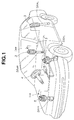
- Fig. 1 is an explanatory view of an arrangement of a vehicular suspension system damping force controlling apparatus in a first preferred embodiment according to the present invention.
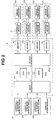
- Fig. 2 is a circuit block diagram of a control unit and its peripheral circuits of the shock absorber damping force controlling apparatus shown in Fig. 1.
- Fig. 3 is a partially sectional view of each shock absorber SA used in the first embodiment shown in Figs. 1 and 2.
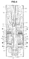
- Fig. 4 is an enlarged, partially sectional view of the representative shock absorber SA shown in Fig. 3.
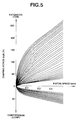
- Fig. 5 is a characteristic graph representing damping forces with respect to a piston speed of the representative shock absorber SA shown in Figs. 3 and 4.
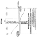
- Fig. 6 is a damping coefficient characteristic graph representing damping force control regions corresponding to stepped positions of an adjuster installed in the representative shock absorber SA associated with a stepping motor according to the rotation of the representative pulse (stepping) motor shown in Figs. 2 and 3.
- Figs. 7A, 7B, and 7C are cross sectional views cut away along a line K - K of Fig. 4 representing an essential part of the representative shock absorber shown in Fig. 4.
- Figs. 8A, 8B, and 8C are cross sectional views cut away along lines L - L and M - M of Fig. 4 representing an essential part of the representative shock absorber SA shown in Figs. 3 and 4.
- Figs. 9A, 9B, and 9C are cross sectional views cut away along a line N - N of Fig. 4 representing an essential part of the representative shock absorber shown in Figs. 3 and 4.
- Fig. 10 is a damping force characteristic graph when an extension stroke side (phase) is in a hard damping force characteristic with respect to the piston of the representative shock absorber SA shown in Fig. 4.
- Fig. 11 is a damping force characteristic graph when both extension and compression stroke sides (phases) are in soft damping force states.
- Fig. 12 is a damping force characteristic graph when the compression stroke side (phase) is in a hard damping force state.
- Fig. 13 is a circuit block diagram of a signal processing circuit in the suspension system damping force controlling apparatus in the first embodiment according to the present invention shown in Fig. 1 in which a control signal is formed for each of the shock absorbers.
- Fig. 14 is an operational flowchart executed in a control unit in the case of the first embodiment according to the present invention.
- Figs. 15A, 15B, 15C, 15D, and 15E are integrally a timing chart indicating a damping force characteristic control operation of a control unit in the first preferred embodiment according to the present invention.
- Fig. 16A, 16B, 16C, 16D, and 16E are integrally a timing chart indicating a formed state of the control signal which is formed on the basis of a vertical velocity of a sprung mass and a relative velocity between the sprung mass and an unsprung mass.
- Figs. 17A and 17B are graphs representing gain and phase characteristics in the transfer function in the case of the first embodiment, an approximation (approximate) transfer function to the transfer function in an alternative of the embodiment, and an approximation (approximate) band pass filter in an alternative of the embodiment, respectively.
- Fig. 18 is an explanatory view of a transfer function calculation model in the damping force controlling apparatus in the case of the first embodiment.
- Figs. 19A and 19B are simplified circuit block diagrams of the approximation (approximation) band pass filter in an alternative of the embodiment and the approximation high pass filter in an alternative of the first embodiment of the damping force characteristic controlling apparatus.
- Fig. 1 shows a whole system configuration of a vehicular suspension system damping force characteristic controlling apparatus in a first preferred embodiment according to the present invention.
- shock absorbers SA FL , SA FR , SA RL , and SA RR denoted by SA since all shock absorbers (having the mutually same structures) are interposed between given parts of a vehicular body (sprung mass) and respective road (tire) wheels (unsprung mass).
- the road wheels comprise front left road wheel, front right road wheel, rear left road wheel, and rear right road wheels of the vehicle. It is noted that the above-described given parts of the vehicular body indicate front left and right road wheel positions and rear left and right road wheel positions.
- (vertical, i.e., upward and downward) acceleration (G; gravity) sensors 1 (1 FL , 1 FR , 1 RR ) are attached onto given parts of the vehicular body adjacent to the front left and right road wheel side and rear right road wheel side shock absorbers SA , each being provided to detect a vertical sprung mass acceleration acted upon the sprung mass (vehicle body).
- a control unit 4 is installed at a given part of the vehicle to receive signals derived from the acceleration sensors 1 FR , 1 FL , and 1 RR , processes these signals, and outputs drive signals to respective actuators (,i.e., stepping motors) for the respective four shock absorbers SA.
- Fig. 2 shows a circuit block diagram of the vehicular shock absorber damping force controlling apparatus in the first embodiment according to the present invention shown in Fig. 1.
- control unit 4 is installed on a portion of the vehicular body near to a driver's seat.
- the control unit 4 includes: an input interface circuit 4a; a CPU (Central Processing Unit) 4b; a memory 4bb having a ROM (Read Only Memory) and a RAM (Random Access Memory); an output interface 4aa, and actuator driver circuits 4c; and a common bus.
- CPU Central Processing Unit
- memory 4bb having a ROM (Read Only Memory) and a RAM (Random Access Memory)
- output interface 4aa and actuator driver circuits 4c
- a common bus a common bus.
- the control unit 4 is provided with the respective drivers 4c connected between the output interface 4aa and the corresponding stepping motors 3.
- the control unit 4 shown in Fig. 2 is provided with a signal processing circuit in terms of its hardware structure as shown in Fig. 13. The explanation of Fig. 13 will be described later.
- Fig. 3 show a cross sectional view of each shock absorber SA shown in Figs. 1 and 2.
- the shock absorber SA as shown in Fig. 3, includes: a cylinder 30, a (movable) piston 31 defining an upper portion chamber A and a lower portion chamber B; an outer envelope 33 in which a reservoir chamber 32 is formed on an outer peripheral end of the cylinder 30; a base 34 which defines the lower portion chamber B and the reservoir chamber 32; a guide member 35 which guides a sliding motion of a piston rod 7 with the other end of which the movable piston 31 is linked; a suspension spring 36 interposed between the outer envelope 33 and vehicle body; and a bumper rubber 37.
- Each stepping motor 3 shown in Figs. 1 and 2 is installed in an upper position of the corresponding one of the shock absorbers SA, as shown in Fig. 3, so as to operatively rotate an adjuster 40 (refer to Fig. 4) via a control rod 70 in response to a rotation drive signal from the corresponding one of the actuator drivers (circuits) 4c.
- a rotating shaft of the corresponding one of the stepping motors 3 is mechanically connected to the corresponding adjuster 40 within each shock absorbers SA via the control rod 70.
- Fig. 4 shows an enlarged cross sectional view representing a part of the piston assembly 31 and its surrounding part of each of the shock absorbers SA.
- the piston 31 is formed with penetrating holes 31a and 31b therethrough.
- the piston 31 is provided with a compression phase attenuation valve 20 and an extension phase attenuating valve 12, both of the valves 20, 12 respectively opening and closing the respective penetrating holes 31a and 31b.
- a stud 38 is spirally meshed with and fixed to a bound stopper 41 spirally meshed with and fixed to a tip end of the piston rod 7.
- the stud 38 is penetrated through the piston 31.
- the stud 38 is formed with a communication hole 39 so as to communicate the upper portion chamber A and the lower portion chamber B, the communication hole 39 forming flow passages (an extension phase second flow passage E, extension phase third flow passage F, bypass flow passage G, and compression phase second flow passage J as will be described later).
- the adjuster 40 which changes flow passage cross sectional areas of the above-described flow passages is provided within the communication hole 39.
- an extension stroke side (phase) check valve 17 and a compression (or contraction) stroke side (compression phase) check valve 22 are also installed on an outer periphery of the stud 38, which enable and disable the fluid flow through the above-described flow passages formed by the communication hole 39 in accordance with a direction of the flow of the fluid.
- the adjuster 40 is rotatable by means of the corresponding one of the actuators (stepping motors) 3 via the control rod 70.
- the stud 38 is formed with a first port 21, a second port 13, a third port 18, a fourth port 14, and fifth port 16, respectively, in an upper order.
- the adjuster 40 is formed with a hollow portion 19, a first lateral hole 24, and a second lateral hole 25, both lateral holes communicating the internal and external portions of the adjuster 40.
- a longitudinal groove 23 is formed on an outer peripheral portion.
- four flow passages are formed between the upper portion chamber A and lower portion chamber B as the fluid flow passages when the piston stroke indicates the extension phase: that is to say, 1) an extension stroke side (phase) first flow passage D such that the fluid passes the penetrating hole 31b, a valve opened internal side of the extension stroke side (phase) attenuation valve 12, and reaches the lower portion chamber B; 2) an extension stroke side (phase) second flow passage E in which the fluid flows through the second port 13, the longitudinal groove 23, the fourth port 14, a valve opened outer peripheral side of the extension stroke side (phase) attenuation valve 12, and reaches the lower portion chamber B; 3) an extension stroke side (phase) third flow passage F in which the fluid passes through the second port 13, the longitudinal groove 23, and the fifth port 16; and 4) a bypass flow passage G in which the fluid passes through the third port 18, the second lateral hole 25, and the hollow portion 19 and reaches the lower portion chamber B.
- the three fluid flow passages through which the fluid can be caused to flow during the compression stroke side (phase) of the piston 31 include: 1) a compression stroke side (phase) first flow passage H in which the fluid flows through the penetrating hole 31a and valve opened compression stroke side (phase) attenuation valve 20; 2) a compression stroke side (phase) second flow passage J in which the hollow portion 19, the first lateral hole 24, the first port 21, and the opened compression stroke side (phase) check valve 22 and reaches the upper portion chamber A; and 3) the bypass passage G in which the fluid flows through the hollow portion 19, the second lateral hole 25,, and the third port 18.
- the shock absorber SA is so arranged and constructed as to be enabled to change the damping force characteristics at a multiple stage in its damping characteristic, as shown in Fig. 5, either in the extension phase or compression phase when the adjuster 40 is pivoted according to the rotation of the corresponding one of the stepping motors 3.
- Fig. 6 shows relationships between the rotated position of the adjuster 40 and damping force characteristics at both the extension stroke (phase) and compression phase with respect to the piston 31.
- the damping force coefficient at the extension stroke side (phase) can be changed at the multiple stage from a maximum hard to a minimum hard characteristic but the compression stroke side is fixed at a soft position (hereinafter, referred to as an extension stroke side hard region HS).
- the damping force coefficient at the compression stroke side (phase) is only changeable to a hard region from the maximum hard to the minimum hard characteristic at the multiple stages and the damping force characteristic at in the compression stroke side is fixed to the soft position (hereinafter, referred to as a compression hard region SH).
- Fig. 10 shows the damping force characteristic of the representative shock absorber SA when the adjuster 40 is positioned at 1 of Fig. 6.
- Fig. 11 shows that when the adjuster 40 is positioned at 2 of Fig. 6.
- Fig. 12 shows that when the adjuster 40 is positioned at 3 of Fig. 6.
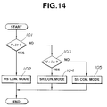
- Fig. 14 shows an operational flowchart for explaining the content of the damping force characteristic control operation for each shock absorber SA executed in the control unit 4.
- the CPU 4b determines whether the formed control signal V (for each one of the shock absorbers SA) is increased and exceeds a predetermined positive threshold value ⁇ T . If Yes at the step 101, the routine goes to a step 102 in which the corresponding one of the shock absorber SA is set to as the extension phase hard region HS.
- the routine goes to a step 103 in which the CPU 4b determines whether the control signal V is below a predetermined negative threshold value - ⁇ c .
- the routine goes to a step 104 in which the damping force characteristic of the corresponding one of the shock absorbers SA is set to as the compression phase hard region SH.
- the routine goes to a step 105, namely, if the CPU 4b determines that the value of the control signal V falls in a range from + ⁇ T to the minus - ⁇ C , the corresponding one of the shock absorbers SA is set to as each of the respective extension and compression phases being the soft region SS.
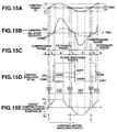
- Fig. 15A through 15E show integrally a timing chart for explaining the operation of the control unit 4 and shock absorber(s) SA in the case of the first embodiment.
- the corresponding one of the shock absorbers SA is controlled so that the extension phase hard region HS is provided and the compression phase is set at a predetermined low (soft) damping force characteristic.
- the damping force characteristic at the extension phase is increased to provide a target damping force characteristic position P T in proportion to the magnitude of the control signal V .
- the compression phase hard region SH is provided so that the extension phase damping force characteristic is fixed to the low predetermined damping force characteristic and the damping force characteristic at the compression phase is varied to provide a target damping force characteristic position P C in proportion to the value of the control signal V.
- a symbol a of Fig. 15C denotes a region in which the direction of the control signal V formed on the basis of the sprung mass vertical velocity ⁇ x and relative velocity ( ⁇ x - ⁇ x 0) is inverted from the negative value (downward) to the positive value (upward).
- the relative velocity ( ⁇ x - ⁇ x 0) still provides the negative value (the phase of the shock absorber SA is at the compression phase) so that the corresponding shock absorber SA is controlled at the extension phase hard region HS on the basis of the direction of the control signal V and the phase of the corresponding shock absorber SA is at the extension phase.
- the extension phase from which the piston 31 of the shock absorber SA is moved away provides the hard characteristic which is proportional to the value of the control signal V.
- a region b denotes a region in which the direction (direction discriminating sign) of the control signal V is still positive (upward value) and the relative velocity ( ⁇ x - ⁇ x 0) is switched from the negative value to the positive value (extension phase from which the piston of the corresponding shock absorber SA is moved away).
- the shock absorber SA since the shock absorber SA is controlled in the mode of the extension phase hard region HS on the basis of the direction of the control signal V, the stroke direction of the corresponding shock absorber SA is the extension phase.
- the extension phase side of the shock absorber SA provides the hard characteristic proportional to the value of the control signal V.
- a region c denotes a region in which the control signal V is inverted from the positive value (upward) to the negative value (downward).
- this region c since the corresponding shock absorber SA is controlled to the compression phase hard region SH on the basis of the direction (direction discriminating sign) of the control signal V, this region c provides the phase (in this region c, the extension phase) at which the piston of the corresponding shock absorber SA is moved with the soft (predetermined low damping force characteristic) characteristic.
- a region d denotes a region in which the control signal V is still at the negative value (downward) and the relative velocity ( ⁇ x - ⁇ x 0) is changed from the positive value to the negative value (the phase at which the piston of the corresponding shock absorber SA is at the extension phase side).
- the corresponding shock absorber SA is controlled at the compression phase hard region SH on the basis of the direction of the control signal. Hence, the stroke (phase) of the corresponding shock absorber is at the compression phase.
- the (compression) phase at which the piston of the shock absorber SA is moved provides the hard characteristic proportional to the value of the control signal V.
- the damping force characteristic position P T or P C at the phase to which the control is switched has already been switched to the hard characteristic side at the previous regions a and c. Consequently, the switching from the soft characteristic to the hard characteristic has been carried out without delay in time.
- Fig. 13 shows the configuration of a signal processing circuit for forming the control signal V by which the generation of the control force F based on the Sky Hook theorem (theory) according to the sprung mass vertical velocity ⁇ x and relative velocity ( ⁇ x - ⁇ x 0).
- the control unit 4 calculates the four road wheel side sprung mass vertical accelerations G FL , G FR , G RL , and G RR on the basis of the vertical acceleration signals of the vehicle body adjacent to the front right and left road wheel side shock absorbers SA FL , SA FR , and the rear right road wheel side shock absorber SA RR detected and outputted from the respective three sprung mass vertical acceleration (G) sensors 1 FL , 1 FR , and 1 RR .
- G RL is estimated from these signals from the three vertical G sensors.
- a vehicular roll acceleration G R is derived on the basis of the following equation (5) from the front right and left road wheel side vertical sprung mass acceleration signals G FL and G FR .
- G R (G FR - G FL )/2
- the control unit 4 integrates or passes through a low pass filter the four road wheel side sprung mass vertical accelerations G FL , G FR , G RL , and G RR and the roll acceleration G R so as to convert the acceleration signals G FL through G R to sprung mass vertical velocity x' (V') (V' -FL , V' -FR , V' -RL , V' -RR ) and the roll velocity V R , respectively.
- the control unit 4 carries out a band pass filter processing in order to increase a signal isolability from those signal components except a target frequency band within which the control of the damping force characteristic is carried out. That is to say, a first band pass filter BPF1 and a second band pass filter BPF2 extract bounce velocity signals V BFR , V BFL , V BRR , and B BRL within a bounce resonance frequency band of the vehicle. In addition, a third band pass filter BPF3 derives a roll velocity signal V R with a vehicular roll resonance frequency band as a target (a center).
- the bounce coefficients ⁇ f and ⁇ r are set mutually independently of the front road wheel side and rear wheel side bouncing so as to be capable of coping with a difference in a magnitude of vehicular behaviors according to the difference in the specifications (weights, spring constants, and so on) at the vehicular front road wheel side and rear road wheel side.
- rolling coefficients r f and r r are set independently at the front road wheel side and rear road wheel side so that the control forces against the vehicular behaviors in the rolling direction due to an external force (lateral acceleration) exerted on the vehicle body during a vehicular steering operation do not become insufficient.
- the control unit 4 at a block B8 derives the relative velocities between the sprung mass and unsprung mass ( ⁇ x - ⁇ x 0) ⁇ ( ⁇ x - ⁇ x 0) FL , ( ⁇ x - ⁇ x 0) FR , ( ⁇ x - ⁇ x 0) RL , ( ⁇ x - ⁇ x 0) RR ⁇ , respectively, from the four road wheel side sprung mass vertical acceleration signals G FL , G FR , G RL , and G RR calculated at the block B1 using a (predetermined) transfer function G U(S) of the relative velocity ( ⁇ x - ⁇ x 0) with respect to the related sprung mass (vertical) acceleration.
- S denotes a Laplace operator
- Q -m 1 ⁇ c 2
- R -m 1 ⁇ k 2
- F c 1 ⁇ c 2
- D c 1 ⁇ c 2
- D c 1 ⁇ k 2 + k 1 ⁇ c 2
- E k 1 ⁇ k 2 .
- Fig. 18 shows an explanatory view for explaining a transfer function calculation model.
- x1 denotes a sprung mass input
- x2 denotes an unsprung mass input
- x3 denotes a road surface input from a road surface
- m1 denotes the sprung mass
- m2 denotes the unsprung mass
- c1 denotes an attenuation coefficient of the suspension system
- c2 denotes an attenuation coefficient of the corresponding one of the road wheels
- k1 denotes a spring constant of the suspension system
- k2 denotes a spring constant of the corresponding one of the road wheels.
- the control unit 4 derives the control signal V (extension phase control signals V FR-T , V FL-T , V RR-T , V RL-T and compression phase signals V FR-C , V FL-C , V RR-C , V RL-C ) using the following equations (7) through (10) and (7)' through (10)' from the related sprung mass component signal V H (V FR-RH through V RL-LH ) and the relative velocity signal ( ⁇ x - ⁇ x 0) formed at the block B1 and B8.
- each relative velocity ( ⁇ x - ⁇ x 0) is directly supplied to the block B9, a smoothing circuit enclosed by a phantom line may alternatively be interposed between the blocks B8 and B9.
- Fig. 16A through 16E show integrally a timing chart for explaining the formed state of the control signal V in the exemplified signal processing circuit shown in Fig. 13.
- the sprung mass vertical velocity ⁇ x is varied with time at a relatively low frequency form as shown in Fig. 16A and the relative velocity ( ⁇ x - ⁇ x 0) at the block B8 in Fig. 13 is varied with time in a relatively high frequency form as shown in Fig. 16B.
- the control signal V is formed on the basis of the following equation (V ⁇ ( ⁇ x)/( ⁇ x - ⁇ x 0 ) , resulting the control signal form shown in Fig. 16C, so that an upper limit and a lower limit is placed at the plus side and minus side of the control signal V.
- the signal form of the control signal approaches to that of Fig. 15A.
- a first mode corresponds to, so called, extension phase hard characteristic and compression phase soft characteristic (HS control mode in Fig. 14) and a second mode corresponds to, so called, extension phase soft characteristic and compression phase hard characteristic (SH control mode in Fig. 14). Consequently, the damping force (C) as shown in Fig. 16E is exhibited.
- the suspension system damping force controlling apparatus in the first embodiment has the following advantages:
- the three sprung mass G sensors (1 FL , 1 FR , and 1 RR ) are installed at vehicle body of the front left and right road wheel sides and rear right road wheel sides, the number of installed positions is arbitrary.
- the suspension system damping force controlling apparatus according to the present invention can be applied to that system in which the single sprung mass (vertical ) G (G means gravity) sensor is only installed at the front road wheel side. In this case, the other sprung mass accelerations are calculated on the basis of the output signal of the single G sensor.
- the above-described transfer function equation (6) is used as the transfer function to derive the relative velocity ( ⁇ x - ⁇ x 0) from the related sprung mass acceleration signal.
- the following lower-order (approximation) transfer function G S (refer to equation (11)) may alternatively be used since the capacity of the programming becomes large and the discrete equation becomes complex when the above-described higher-order transfer function equation (10) is used.
- G S RS/(DS + E)
- a normally used band pass filter BPF or a high pass filter HPF may be used as shown in Fig. 19A or 19B.
- the frequency band to pass the related sprung mass vertical acceleration signal through this alternative band pass filter is from 9Hz to 13Hz.
- the frequency band to pass the related sprung mass vertical acceleration signal through this alternative high pass filter is 10Hz or higher.
- HPF high pass filter
- the front and rear road wheel side control gains g f and g r in the above-described equations (7) through (10) and (7)' through (10)' to derive the control signal V may be varied according to the vehicle speed detected by a vehicle speed sensor (denoted by a phantom line ) shown in Fig. 2.
Landscapes
- Engineering & Computer Science (AREA)
- Mechanical Engineering (AREA)
- Vehicle Body Suspensions (AREA)
- Fluid-Damping Devices (AREA)
Abstract
In apparatus and method for controlling a damping force characteristic for a vehicular suspension system, a relative velocity between a sprung mass and an unsprung mass is calculated using a predetermined transfer function from a sprung mass vertical velocity derived on the basis of a sprung mass acceleration signal. The predetermined transfer function is, in a preferred embodiment, expressed as 
, wherein 
, 
, 
, 
, 
, S denotes a Laplace operator, c₁ denotes an attenuation constant of each of the shock absorbers, c₂ denotes an attenuation constant of the corresponding one of road wheels, k₁ denotes a spring constant of the shock absorber, k₂ denotes a spring constant of the corresponding one of the road wheels, m₁ denotes the sprung mass, and m₂ denotes the unsprung mass.
Description
- The present invention relates to apparatus and method for optimally controlling a damping force characteristic of a vehicular suspension system of an automotive vehicle.
- A Japanese Patent Application First Publication No. Showa 61-163011 exemplifies a first previously proposed suspension system damping force characteristic controlling apparatus, the suspension system having a plurality of shock absorbers.
- In the first previously proposed suspension damping force characteristic controlling apparatus, a sprung mass vertical velocity indicative signal and a relative velocity indicative signal between a sprung mass of a vehicle body and unsprung mass of a corresponding road wheel, the sprung mass and unsprung mass being located at a position adjacent to each shock absorber, are detected and outputted.
- If direction discriminating signs of the sprung mass vertical velocity indicative signal and the relative velocity indicative signal are coincident with each other, the damping force characteristic of the corresponding one of the shock absorbers is set to a hard characteristic. If either one of the sprung mass vertical velocity signal and the unsprung mass vertical velocity signal is not coincident with the other of both of velocity signals, the damping force characteristic of the corresponding one of the shock absorbers is set to a soft characteristic. In this way, the damping force characteristic controls based on a Sky Hook theorem (theory) are carried out individually for the respective shock absorbers and independently of each other.
- In addition, a Japanese Patent Application First Publication No. Heisei 4-63712 exemplifies a second previously proposed suspension system damping force characteristic controlling apparatus, the suspension system having the plurality of shock absorbers.
- In the second previously proposed suspension damping force characteristic controlling apparatus, such a shock absorber as having a first mode in which the hard characteristic is exhibited in an extension phase with the soft characteristic exhibited in a compression phase and a second mode in which the hard characteristic is exhibited in the compression phase with the soft characteristic exhibited in the extension phase is used for each shock absorber. Then, a switching control is carried out between the first and second modes according to a direction of the sprung mass vertical velocity Δx (hereinafter, often simply referred to as a sprung mass velocity).
- In more details, in the second previously proposed suspension damping force characteristic controlling apparatus, when the direction discriminating sign of the sprung mass vertical velocity signal Δx indicates upward (namely, plus +), the damping force switching control is switched to the first mode so that the hard damping force characteristic is exhibited in the extension phase. When the direction discriminating sign of the sprung mass vertical velocity indicates downward (namely, minus -), the damping force characteristic is switched to the second mode so that the hard damping characteristic is exhibited in the compression phase. Then, the hard damping force characteristic to be controlled in either of the extension or compression phase is further controlled to provide a damping force characteristic position P proportional to the magnitude of the sprung mass velocity Δx so that in a damping suppression region in which both direction discriminating signs of the sprung mass vertical velocity Δx and relative velocity (Δx - Δx ₀) between the sprung mass and unsprung mass (hereinafter, often simply referred to as a relative velocity) are coincident with each other, the damping characteristic at either one of the extension or compression phase which is required to be controlled at this time of coincidence of direction discriminating signs is further controlled so that its hard damping force characteristic is proportional to the sprung mass velocity Δx and in an oscillation applied region in which both of the direction discriminating signs thereof are not coincident with each other, the damping force characteristic at either one of the extension or compression phase which is required to be controlled is controlled so as to provide a predetermined low (soft) damping force. The second previously proposed suspension damping force controlling apparatus can achieve, with a rather simple construction, such a basic Sky Hook theorem as described above.
- In each of the first and second previously proposed suspension damping force controlling apparatuses, the sprung mass vertical velocity Δx is derived by integrating or passing through a low pass filter a sprung mass vertical acceleration signal detected by a sprung mass vertical acceleration sensor installed at the corresponding vehicle body position. In addition, the relative velocity between the sprung mass and unsprung mass is derived by differentiating or passing through a high pass filter a relative displacement indicative signal outputted by a stroke sensor installed on the corresponding unsprung mass.
- In the above-described first and second previously proposed suspension system damping force controlling apparatuses, it is necessary to install the stroke sensor onto the unsprung mass portion to detect the relative velocity between the sprung mass and unsprung mass. Therefore, the system configuration of each previously proposed suspension damping force controlling apparatus becomes complicated and it is difficult to actually mount each of the stroke sensors into the vehicle. Furthermore, a cost of manufacturing the suspension system damping force characteristic becomes high.
- It is an object of the present invention to provide apparatus and method for controlling a damping force of a vehicular suspension system which can achieve a simpler and less expensive construction of the damping force controlling apparatus, a calculation of a relative velocity between a sprung mass of a vehicle body and an unsprung mass of a corresponding one of road wheels (road wheel assemblies) being carried out without each of the relative velocity detecting sensors such as stroke sensors.
- According to one aspect of the present invention, there is provided with an apparatus for controlling a damping force characteristic of a vehicular suspension system, said suspension system having shock absorber means interposed between a sprung mass of a vehicle body and unsprung mass of a corresponding one of road wheels, said apparatus comprising: a) an actuator which is so arranged and constructed as to change the damping force characteristic to be exerted by said shock absorber means in response to an input signal; b) detecting means for detecting a behavior of the vehicle body as the sprung mass and outputting a first signal indicating the behavior of the vehicle body; c) velocity converting means for converting the first signal outputted by said detecting means into a second signal indicating a sprung mass vertical velocity of the sprung mass; d) determining means for determining a relative velocity between the sprung mass and unsprung mass and outputting a third signal indicating the determined relative velocity between the sprung mass and unsprung mass; e) control signal generating means for generating and outputting a control signal on the basis of the second signal outputted by said velocity converting means and the third signal outputted by said calculating means; and f) controlling means for controlling the damping force characteristic of said shock absorber means via said actuator on the basis of said control signal, characterized in that said relative velocity determining means comprises calculating means for calculating the relative velocity between the sprung mass (m₁) and the unsprung mass (m₂) using a predetermined transfer function between the first signal outputted by said detecting means and outputting the third signal indicating the calculated relative velocity between the sprung mass and unsprung mass.
- According to another aspect of the present invention, there is provided with a method for controlling a damping force characteristic of a vehicular suspension system, said vehicular suspension system having shock absorber means which is interposed between a sprung mass of a vehicle body and an unsprung mass of a corresponding one of road wheels, said method comprising the steps of: a) detecting a behavior of the vehicle body as the sprung mass and outputting a first signal indicating the behavior of the vehicle body; b) converting the first signal outputted by said detecting means into a second signal indicating a sprung mass vertical velocity of the sprung mass; c) calculating a relative velocity between the sprung mass and unsprung mass using a predetermined transfer function from the first signal outputted at said step a) and outputting a third signal indicating the calculated relative velocity between the sprung mass and unsprung mass; and d) generating and outputting the control signal according to the second signal outputted at said step b) and third signal outputted at said step c), said control signal being supplied to damping force characteristic controlling means so that the damping force exerted by said shock absorber means is controlled on the basis of the control signal, characterized in that at said step c), calculating the relative velocity between the sprung mass and unsprung mass using a predetermined transfer function from the first signal outputted at said step a).
- Fig. 1 is an explanatory view of an arrangement of a vehicular suspension system damping force controlling apparatus in a first preferred embodiment according to the present invention.
- Fig. 2 is a circuit block diagram of a control unit and its peripheral circuits of the shock absorber damping force controlling apparatus shown in Fig. 1.
- Fig. 3 is a partially sectional view of each shock absorber SA used in the first embodiment shown in Figs. 1 and 2.
- Fig. 4 is an enlarged, partially sectional view of the representative shock absorber SA shown in Fig. 3.
- Fig. 5 is a characteristic graph representing damping forces with respect to a piston speed of the representative shock absorber SA shown in Figs. 3 and 4.
- Fig. 6 is a damping coefficient characteristic graph representing damping force control regions corresponding to stepped positions of an adjuster installed in the representative shock absorber SA associated with a stepping motor according to the rotation of the representative pulse (stepping) motor shown in Figs. 2 and 3.
- Figs. 7A, 7B, and 7C are cross sectional views cut away along a line K - K of Fig. 4 representing an essential part of the representative shock absorber shown in Fig. 4.
- Figs. 8A, 8B, and 8C are cross sectional views cut away along lines L - L and M - M of Fig. 4 representing an essential part of the representative shock absorber SA shown in Figs. 3 and 4.
- Figs. 9A, 9B, and 9C are cross sectional views cut away along a line N - N of Fig. 4 representing an essential part of the representative shock absorber shown in Figs. 3 and 4.
- Fig. 10 is a damping force characteristic graph when an extension stroke side (phase) is in a hard damping force characteristic with respect to the piston of the representative shock absorber SA shown in Fig. 4.
- Fig. 11 is a damping force characteristic graph when both extension and compression stroke sides (phases) are in soft damping force states.
- Fig. 12 is a damping force characteristic graph when the compression stroke side (phase) is in a hard damping force state.
- Fig. 13 is a circuit block diagram of a signal processing circuit in the suspension system damping force controlling apparatus in the first embodiment according to the present invention shown in Fig. 1 in which a control signal is formed for each of the shock absorbers.
- Fig. 14 is an operational flowchart executed in a control unit in the case of the first embodiment according to the present invention.
- Figs. 15A, 15B, 15C, 15D, and 15E are integrally a timing chart indicating a damping force characteristic control operation of a control unit in the first preferred embodiment according to the present invention.
- Fig. 16A, 16B, 16C, 16D, and 16E are integrally a timing chart indicating a formed state of the control signal which is formed on the basis of a vertical velocity of a sprung mass and a relative velocity between the sprung mass and an unsprung mass.
- Figs. 17A and 17B are graphs representing gain and phase characteristics in the transfer function in the case of the first embodiment, an approximation (approximate) transfer function to the transfer function in an alternative of the embodiment, and an approximation (approximate) band pass filter in an alternative of the embodiment, respectively.
- Fig. 18 is an explanatory view of a transfer function calculation model in the damping force controlling apparatus in the case of the first embodiment.
- Figs. 19A and 19B are simplified circuit block diagrams of the approximation (approximation) band pass filter in an alternative of the embodiment and the approximation high pass filter in an alternative of the first embodiment of the damping force characteristic controlling apparatus.
- Reference will hereinafter be made to the drawings in order to facilitate a better understanding of the present invention.
- Fig. 1 shows a whole system configuration of a vehicular suspension system damping force characteristic controlling apparatus in a first preferred embodiment according to the present invention.
- Four shock absorbers SAFL, SAFR, SARL, and SARR (it is noted that subscripts FL denotes a front left road wheel side (position) , FR denotes a front right road wheel side (position), RL denotes a rear left road wheel side (position), RR denotes a rear right road wheel side (position), and a representative shock absorber is simply denoted by SA since all shock absorbers (having the mutually same structures) are interposed between given parts of a vehicular body (sprung mass) and respective road (tire) wheels (unsprung mass). The road wheels comprise front left road wheel, front right road wheel, rear left road wheel, and rear right road wheels of the vehicle. It is noted that the above-described given parts of the vehicular body indicate front left and right road wheel positions and rear left and right road wheel positions.
- As shown in Fig. 1, (vertical, i.e., upward and downward) acceleration (G; gravity) sensors 1 (1FL, 1FR, 1RR) are attached onto given parts of the vehicular body adjacent to the front left and right road wheel side and rear right road wheel side shock absorbers SA , each being provided to detect a vertical sprung mass acceleration acted upon the sprung mass (vehicle body). A
control unit 4 is installed at a given part of the vehicle to receive signals derived from theacceleration sensors - Fig. 2 shows a circuit block diagram of the vehicular shock absorber damping force controlling apparatus in the first embodiment according to the present invention shown in Fig. 1.
- Referring to Figs. 1 and 2, the
control unit 4 is installed on a portion of the vehicular body near to a driver's seat. Thecontrol unit 4 includes: an input interface circuit 4a; a CPU (Central Processing Unit) 4b; a memory 4bb having a ROM (Read Only Memory) and a RAM (Random Access Memory); an output interface 4aa, andactuator driver circuits 4c; and a common bus. - The
control unit 4 is provided with therespective drivers 4c connected between the output interface 4aa and thecorresponding stepping motors 3. - The
control unit 4 shown in Fig. 2 is provided with a signal processing circuit in terms of its hardware structure as shown in Fig. 13. The explanation of Fig. 13 will be described later. - Next, Fig. 3 show a cross sectional view of each shock absorber SA shown in Figs. 1 and 2.
- The shock absorber SA, as shown in Fig. 3, includes: a
cylinder 30, a (movable)piston 31 defining an upper portion chamber A and a lower portion chamber B; anouter envelope 33 in which areservoir chamber 32 is formed on an outer peripheral end of thecylinder 30; abase 34 which defines the lower portion chamber B and thereservoir chamber 32; aguide member 35 which guides a sliding motion of apiston rod 7 with the other end of which themovable piston 31 is linked; asuspension spring 36 interposed between theouter envelope 33 and vehicle body; and abumper rubber 37. - Each stepping
motor 3 shown in Figs. 1 and 2 is installed in an upper position of the corresponding one of the shock absorbers SA, as shown in Fig. 3, so as to operatively rotate an adjuster 40 (refer to Fig. 4) via acontrol rod 70 in response to a rotation drive signal from the corresponding one of the actuator drivers (circuits) 4c. A rotating shaft of the corresponding one of thestepping motors 3 is mechanically connected to thecorresponding adjuster 40 within each shock absorbers SA via thecontrol rod 70. - Fig. 4 shows an enlarged cross sectional view representing a part of the
piston assembly 31 and its surrounding part of each of the shock absorbers SA. - As shown in Fig. 4, the
piston 31 is formed with penetratingholes piston 31 is provided with a compressionphase attenuation valve 20 and an extensionphase attenuating valve 12, both of thevalves holes stud 38 is spirally meshed with and fixed to a boundstopper 41 spirally meshed with and fixed to a tip end of thepiston rod 7. - The
stud 38 is penetrated through thepiston 31. In addition, thestud 38 is formed with acommunication hole 39 so as to communicate the upper portion chamber A and the lower portion chamber B, thecommunication hole 39 forming flow passages (an extension phase second flow passage E, extension phase third flow passage F, bypass flow passage G, and compression phase second flow passage J as will be described later). Then, theadjuster 40 which changes flow passage cross sectional areas of the above-described flow passages is provided within thecommunication hole 39. - Furthermore, an extension stroke side (phase) check valve 17 and a compression (or contraction) stroke side (compression phase)
check valve 22 are also installed on an outer periphery of thestud 38, which enable and disable the fluid flow through the above-described flow passages formed by thecommunication hole 39 in accordance with a direction of the flow of the fluid. As shown in Fig. 3, theadjuster 40 is rotatable by means of the corresponding one of the actuators (stepping motors) 3 via thecontrol rod 70. - It is noted that the
stud 38 is formed with afirst port 21, asecond port 13, athird port 18, afourth port 14, andfifth port 16, respectively, in an upper order. - On the other hand, referring to Fig. 4, the
adjuster 40 is formed with ahollow portion 19, a firstlateral hole 24, and a secondlateral hole 25, both lateral holes communicating the internal and external portions of theadjuster 40. Alongitudinal groove 23 is formed on an outer peripheral portion. Hence, four flow passages are formed between the upper portion chamber A and lower portion chamber B as the fluid flow passages when the piston stroke indicates the extension phase: that is to say, 1) an extension stroke side (phase) first flow passage D such that the fluid passes the penetratinghole 31b, a valve opened internal side of the extension stroke side (phase)attenuation valve 12, and reaches the lower portion chamber B; 2) an extension stroke side (phase) second flow passage E in which the fluid flows through thesecond port 13, thelongitudinal groove 23, thefourth port 14, a valve opened outer peripheral side of the extension stroke side (phase)attenuation valve 12, and reaches the lower portion chamber B; 3) an extension stroke side (phase) third flow passage F in which the fluid passes through thesecond port 13, thelongitudinal groove 23, and thefifth port 16; and 4) a bypass flow passage G in which the fluid passes through thethird port 18, the secondlateral hole 25, and thehollow portion 19 and reaches the lower portion chamber B. - In addition, the three fluid flow passages through which the fluid can be caused to flow during the compression stroke side (phase) of the
piston 31 include: 1) a compression stroke side (phase) first flow passage H in which the fluid flows through the penetratinghole 31a and valve opened compression stroke side (phase)attenuation valve 20; 2) a compression stroke side (phase) second flow passage J in which thehollow portion 19, the firstlateral hole 24, thefirst port 21, and the opened compression stroke side (phase)check valve 22 and reaches the upper portion chamber A; and 3) the bypass passage G in which the fluid flows through thehollow portion 19, the secondlateral hole 25,, and thethird port 18. - In summary, the shock absorber SA is so arranged and constructed as to be enabled to change the damping force characteristics at a multiple stage in its damping characteristic, as shown in Fig. 5, either in the extension phase or compression phase when the
adjuster 40 is pivoted according to the rotation of the corresponding one of thestepping motors 3. - Fig. 6 shows relationships between the rotated position of the
adjuster 40 and damping force characteristics at both the extension stroke (phase) and compression phase with respect to thepiston 31. - In details, as shown in Fig. 6, when the
adjuster 40 is pivoted in a given counterclockwise direction from a generally center position at which both of the extension and compression phases are in soft damping force characteristic positions (hereinafter, referred to as a soft region SS), the damping force coefficient at the extension stroke side (phase) can be changed at the multiple stage from a maximum hard to a minimum hard characteristic but the compression stroke side is fixed at a soft position (hereinafter, referred to as an extension stroke side hard region HS). On the contrary, when theadjuster 40 is pivoted in a given clockwise direction therefrom, the damping force coefficient at the compression stroke side (phase) is only changeable to a hard region from the maximum hard to the minimum hard characteristic at the multiple stages and the damping force characteristic at in the compression stroke side is fixed to the soft position (hereinafter, referred to as a compression hard region SH). - When, as shown in Fig. 6, the
adjuster 40 is pivoted at any one ofpositions - The damping force characteristics at the
respective positions - Fig. 10 shows the damping force characteristic of the representative shock absorber SA when the
adjuster 40 is positioned at ① of Fig. 6. - Fig. 11 shows that when the
adjuster 40 is positioned at ② of Fig. 6. - Fig. 12 shows that when the
adjuster 40 is positioned at ③ of Fig. 6. - Next, Fig. 14 shows an operational flowchart for explaining the content of the damping force characteristic control operation for each shock absorber SA executed in the
control unit 4. - At a
step 101, the CPU 4b determines whether the formed control signal V (for each one of the shock absorbers SA) is increased and exceeds a predetermined positive threshold value δT. If Yes at thestep 101, the routine goes to astep 102 in which the corresponding one of the shock absorber SA is set to as the extension phase hard region HS. - If NO at the
step 101, the routine goes to astep 103 in which the CPU 4b determines whether the control signal V is below a predetermined negative threshold value - δc. - If YES at the
step 103, the routine goes to astep 104 in which the damping force characteristic of the corresponding one of the shock absorbers SA is set to as the compression phase hard region SH. - If NO at the
step 103, the routine goes to astep 105, namely, if the CPU 4b determines that the value of the control signal V falls in a range from +δT to the minus -δC, the corresponding one of the shock absorbers SA is set to as each of the respective extension and compression phases being the soft region SS. - Fig. 15A through 15E show integrally a timing chart for explaining the operation of the
control unit 4 and shock absorber(s) SA in the case of the first embodiment. - When the control signal V formed on the basis of the sprung mass vertical velocity Δx and relative velocity (Δx - Δx ₀) is varied with time as shown in Fig. 15A and the control signal V falls in a range from the predetermined negative threshold value -δC to the predetermined positive threshold value δT, the corresponding one of the shock absorbers SA is controlled in the soft region SS.
- On the other hand, if the magnitude and direction of the control signal V exceed the predetermined positive threshold value δT, the corresponding one of the shock absorbers SA is controlled so that the extension phase hard region HS is provided and the compression phase is set at a predetermined low (soft) damping force characteristic. At this time, the damping force characteristic at the extension phase is increased to provide a target damping force characteristic position PT in proportion to the magnitude of the control signal V .
- On the other hand, if the magnitude and direction of the control signal V are minus and below the predetermined negative threshold value -δC, the compression phase hard region SH is provided so that the extension phase damping force characteristic is fixed to the low predetermined damping force characteristic and the damping force characteristic at the compression phase is varied to provide a target damping force characteristic position PC in proportion to the value of the control signal V.
- Next, a symbol a of Fig. 15C denotes a region in which the direction of the control signal V formed on the basis of the sprung mass vertical velocity Δx and relative velocity (Δx - Δx ₀) is inverted from the negative value (downward) to the positive value (upward).
- In the region a, the relative velocity (Δx - Δx ₀) still provides the negative value (the phase of the shock absorber SA is at the compression phase) so that the corresponding shock absorber SA is controlled at the extension phase hard region HS on the basis of the direction of the control signal V and the phase of the corresponding shock absorber SA is at the extension phase. Kence, at this region a, the extension phase from which the
piston 31 of the shock absorber SA is moved away provides the hard characteristic which is proportional to the value of the control signal V. - A region b denotes a region in which the direction (direction discriminating sign) of the control signal V is still positive (upward value) and the relative velocity (Δx - Δx ₀) is switched from the negative value to the positive value (extension phase from which the piston of the corresponding shock absorber SA is moved away). At this time, since the shock absorber SA is controlled in the mode of the extension phase hard region HS on the basis of the direction of the control signal V, the stroke direction of the corresponding shock absorber SA is the extension phase. Hence, at the region b, the extension phase side of the shock absorber SA provides the hard characteristic proportional to the value of the control signal V.
- A region c denotes a region in which the control signal V is inverted from the positive value (upward) to the negative value (downward). However, at this region c, since the corresponding shock absorber SA is controlled to the compression phase hard region SH on the basis of the direction (direction discriminating sign) of the control signal V, this region c provides the phase (in this region c, the extension phase) at which the piston of the corresponding shock absorber SA is moved with the soft (predetermined low damping force characteristic) characteristic.
- A region d denotes a region in which the control signal V is still at the negative value (downward) and the relative velocity (Δx - Δx ₀) is changed from the positive value to the negative value (the phase at which the piston of the corresponding shock absorber SA is at the extension phase side). At this time, since the corresponding shock absorber SA is controlled at the compression phase hard region SH on the basis of the direction of the control signal. Hence, the stroke (phase) of the corresponding shock absorber is at the compression phase. In this region d, the (compression) phase at which the piston of the shock absorber SA is moved provides the hard characteristic proportional to the value of the control signal V.
- As described above with reference to Figs. 15A through 15C, when the control signal V based on the sprung mass vertical velocity Δx and relative velocity ( Δx - Δx ₀) and the relative velocity of (Δx - Δx ₀) have the mutually the same direction discriminating signs (regions b and d), the instantaneous phase at which the piston of the shock absorber SA is moved is controlled at the hard characteristic mode. If the mutual signs thereof (V and (Δx - Δx ₀)) are different from each other (regions a and c), the phase at which the piston of the corresponding shock absorber SA is moved is controlled in the soft characteristic. In the first embodiment, the damping force characteristic control based on the Sky Hook theorem is carried out.
- In the first embodiment, at a point of time when the phase at which the piston of the corresponding one of the shock absorbers SA is moved is ended, namely, when the region is transferred from the region a to the region b and from the region c to the region d (hard characteristic to the soft characteristic), the damping force characteristic position PT or PC at the phase to which the control is switched has already been switched to the hard characteristic side at the previous regions a and c. Consequently, the switching from the soft characteristic to the hard characteristic has been carried out without delay in time.
- Next, Fig. 13 shows the configuration of a signal processing circuit for forming the control signal V by which the generation of the control force F based on the Sky Hook theorem (theory) according to the sprung mass vertical velocity Δx and relative velocity (Δx - Δx ₀).
- At a block B1, the
control unit 4 calculates the four road wheel side sprung mass vertical accelerations GFL, GFR, GRL, and GRR on the basis of the vertical acceleration signals of the vehicle body adjacent to the front right and left road wheel side shock absorbers SAFL, SAFR, and the rear right road wheel side shock absorber SARR detected and outputted from the respective three sprung mass vertical acceleration (G)sensors - At a block B2, a vehicular roll acceleration GR is derived on the basis of the following equation (5) from the front right and left road wheel side vertical sprung mass acceleration signals GFL and GFR.

- At a block B3, the
control unit 4 integrates or passes through a low pass filter the four road wheel side sprung mass vertical accelerations GFL, GFR, GRL, and GRR and the roll acceleration GR so as to convert the acceleration signals GFL through GR to sprung mass vertical velocity x' (V') (V'-FL, V'-FR, V'-RL, V'-RR) and the roll velocity VR, respectively. - At a block B4, the
control unit 4 carries out a band pass filter processing in order to increase a signal isolability from those signal components except a target frequency band within which the control of the damping force characteristic is carried out. That is to say, a first band pass filter BPF1 and a second band pass filter BPF2 extract bounce velocity signals VBFR, VBFL, VBRR, and BBRL within a bounce resonance frequency band of the vehicle. In addition, a third band pass filter BPF3 derives a roll velocity signal VR with a vehicular roll resonance frequency band as a target (a center). - At the next block B5, the bounce coefficients αf and αr are set mutually independently of the front road wheel side and rear wheel side bouncing so as to be capable of coping with a difference in a magnitude of vehicular behaviors according to the difference in the specifications (weights, spring constants, and so on) at the vehicular front road wheel side and rear road wheel side.
- At a block B6, rolling coefficients rf and rr ( γf and γr in Fig. 13) are set independently at the front road wheel side and rear road wheel side so that the control forces against the vehicular behaviors in the rolling direction due to an external force (lateral acceleration) exerted on the vehicle body during a vehicular steering operation do not become insufficient.
- At the next block B7, the
control unit 4 calculates four sprung mass component signals VH (VFR-RH, VFL-LH, VRR-RH, VRL-LH):
Front right road wheel side;


- On the other hand, as shown in Fig. 13, the
control unit 4 at a block B8 derives the relative velocities between the sprung mass and unsprung mass (Δx -Δx ₀) {(Δx - Δx ₀)FL, (Δx - Δx ₀)FR, (Δx - Δx ₀)RL, ( Δx -Δx ₀)RR}, respectively, from the four road wheel side sprung mass vertical acceleration signals GFL, GFR, GRL, and GRR calculated at the block B1 using a (predetermined) transfer function GU(S) of the relative velocity (Δx - Δx ₀) with respect to the related sprung mass (vertical) acceleration. - In this embodiment, the transfer function is expressed as follows:

- In the equation (6), S denotes a Laplace operator,


- Fig. 18 shows an explanatory view for explaining a transfer function calculation model.
- As appreciated from Fig. 18, the symbol x₁ denotes a sprung mass input, x₂ denotes an unsprung mass input, x₃ denotes a road surface input from a road surface, m₁ denotes the sprung mass, m₂ denotes the unsprung mass, c₁ denotes an attenuation coefficient of the suspension system, c₂ denotes an attenuation coefficient of the corresponding one of the road wheels, k₁ denotes a spring constant of the suspension system, and k₂ denotes a spring constant of the corresponding one of the road wheels.
- At a block B9, the
control unit 4 derives the control signal V (extension phase control signals VFR-T, VFL-T, VRR-T, VRL-T and compression phase signals VFR-C, VFL-C, VRR-C, VRL-C) using the following equations (7) through (10) and (7)' through (10)' from the related sprung mass component signal VH (VFR-RH through VRL-LH) and the relative velocity signal (Δx - Δx ₀) formed at the block B1 and B8. - Front right road wheel side;


- It is noted that although, in Fig. 13, each relative velocity (Δx - Δx ₀) is directly supplied to the block B9, a smoothing circuit enclosed by a phantom line may alternatively be interposed between the blocks B8 and B9.
- Next, Fig. 16A through 16E show integrally a timing chart for explaining the formed state of the control signal V in the exemplified signal processing circuit shown in Fig. 13.
- In this case, the sprung mass vertical velocity Δx is varied with time at a relatively low frequency form as shown in Fig. 16A and the relative velocity (Δx - Δx ₀) at the block B8 in Fig. 13 is varied with time in a relatively high frequency form as shown in Fig. 16B.
- As shown in Fig. 16C, the control signal V is formed on the basis of the following equation

- In Fig. 16D, in the damping force characteristic position P, a first mode corresponds to, so called, extension phase hard characteristic and compression phase soft characteristic (HS control mode in Fig. 14) and a second mode corresponds to, so called, extension phase soft characteristic and compression phase hard characteristic (SH control mode in Fig. 14). Consequently, the damping force (C) as shown in Fig. 16E is exhibited.
- As described above, the suspension system damping force controlling apparatus in the first embodiment has the following advantages:
- (1) Since relative velocity detecting sensors such as the stroke sensors, installed on the unsprung mass portion for detecting the relative velocity between the sprung mass and unsprung mass can be omitted, the system configuration of the damping force controlling apparatus can be simplified, an easiness in mounting the apparatus in the vehicle can be improved, and a reduction of manufacturing the damping force controlling apparatus can be achieved.
- (2) It is possible to generate the control force in each shock absorber based on the Sky Hook theorem.
- The present invention does not limit to the above-described embodiment and the various modifications may be made without departing from the scope of the appended claims.
- For example, although, in the above-described embodiments, the three sprung mass G sensors (1FL, 1FR, and 1RR) are installed at vehicle body of the front left and right road wheel sides and rear right road wheel sides, the number of installed positions is arbitrary. The suspension system damping force controlling apparatus according to the present invention can be applied to that system in which the single sprung mass (vertical ) G (G means gravity) sensor is only installed at the front road wheel side. In this case, the other sprung mass accelerations are calculated on the basis of the output signal of the single G sensor.
- Furthermore, in the first embodiment, the above-described transfer function equation (6) is used as the transfer function to derive the relative velocity (Δ x - Δx ₀) from the related sprung mass acceleration signal. However, the following lower-order (approximation) transfer function GS (refer to equation (11)) may alternatively be used since the capacity of the programming becomes large and the discrete equation becomes complex when the above-described higher-order transfer function equation (10) is used.

- Alternatively, another approximation function or an approximation filter such as a normally used band pass filter BPF or a high pass filter HPF may be used as shown in Fig. 19A or 19B. In Fig. 19A, the frequency band to pass the related sprung mass vertical acceleration signal through this alternative band pass filter is from 9Hz to 13Hz. In Fig. 19B, the frequency band to pass the related sprung mass vertical acceleration signal through this alternative high pass filter is 10Hz or higher.
- These approximation function and filter are such that gain and phase characteristics in the frequency band requiring the damping force characteristic control are not largely varied. For the gain and phase characteristics of the approximate filter, refer to Figs. 17A and 17B.
- It is noted that the high pass filter HPF may be used since its general equation shown in the following equation (12) is similar to the approximation transfer function shown in the above-described equation (11).


- Finally, the front and rear road wheel side control gains gf and gr in the above-described equations (7) through (10) and (7)' through (10)' to derive the control signal V may be varied according to the vehicle speed detected by a vehicle speed sensor (denoted by a phantom line ) shown in Fig. 2.
Claims (7)
- An apparatus for controlling a damping force characteristic of a vehicular suspension system, said suspension system having shock absorber means interposed between a sprung mass of a vehicle body and unsprung mass of a corresponding one of road wheels, said apparatus comprising:a) an actuator which is so arranged and constructed as to change the damping force characteristic to be exerted by said shock absorber means in response to an input signal;b) detecting means for detecting a behavior of the vehicle body as the sprung mass and outputting a first signal indicating the behavior of the vehicle body;c) velocity converting means for converting the first signal outputted by said detecting means into a second signal indicating a sprung mass vertical velocity of the sprung mass;d) determining means for determining a relative velocity between the sprung mass and unsprung mass and outputting a third signal indicating the determined relative velocity between the sprung mass and unsprung mass;e) control signal generating means for generating and outputting a control signal on the basis of the second signal outputted by said velocity converting means and the third signal outputted by said calculating means; andf) controlling means for controlling the damping force characteristic of said shock absorber means via said actuator on the basis of said control signal,
characterized in that
said relative velocity determining means comprises calculating means for calculating the relative velocity between the sprung mass (m₁) and the unsprung mass (m₂) using a predetermined transfer function between the first signal outputted by said detecting means and outputting the third signal indicating the calculated relative velocity between the sprung mass and unsprung mass. - An apparatus for controlling a damping force characteristic of a vehicular suspension system as claimed in claim 1, characterized in that said predetermined transfer function is expressed as


- An apparatus for controlling a damping force characteristic of a vehicular suspension system as claimed in claim 1, characterized in that said predetermined transfer function used in said calculating means is expressed as follows:


- An apparatus for controlling a damping force characteristic of a vehicular suspension system as claimed in claim 1, characterized in that said calculating means comprises a filter having gain and phase characteristics approximate to said predetermined transfer function.
- An apparatus for controlling a damping force characteristic of a vehicular suspension system as claimed in claim 4, characterized in that said filter is a high pass filter having the transfer function as


- An apparatus for controlling a damping force characteristic of a vehicular suspension system as claimed in claim 4, characterized in that said filter is a band pass filter (BPF) passing the first signal in a frequency band requiring the damping force characteristic control by said controlling means.
- A method for controlling a damping force characteristic of a vehicular suspension system, said vehicular suspension system having shock absorber means which is interposed between a sprung mass of a vehicle body and an unsprung mass of a corresponding one of road wheels, said method comprising the steps of:a) detecting a behavior of the vehicle body as the sprung mass and outputting a first signal indicating the behavior of the vehicle body;b) converting the first signal outputted by said detecting means into a second signal indicating a sprung mass vertical velocity of the sprung mass;c) calculating a relative velocity between the sprung mass and unsprung mass using a predetermined transfer function from the first signal outputted at said step a) and outputting a third signal indicating the calculated relative velocity between the sprung mass and unsprung mass; andd) generating and outputting the control signal according to the second signal outputted at said step b) and third signal outputted at said step c), said control signal being supplied to damping force characteristic controlling means so that the damping force exerted by said shock absorber means is controlled on the basis of the control signal,
characterized in that
at said step c), calculating the relative velocity between the sprung mass and unsprung mass using a predetermined transfer function from the first signal outputted at said step a).
Applications Claiming Priority (2)
| Application Number | Priority Date | Filing Date | Title |
|---|---|---|---|
| JP6235468A JPH0899513A (en) | 1994-09-29 | 1994-09-29 | Vehicle suspension device |
| JP235468/94 | 1994-09-29 |
Publications (2)
| Publication Number | Publication Date |
|---|---|
| EP0704327A2 true EP0704327A2 (en) | 1996-04-03 |
| EP0704327A3 EP0704327A3 (en) | 1997-07-09 |
Family
ID=16986539
Family Applications (2)
| Application Number | Title | Priority Date | Filing Date |
|---|---|---|---|
| EP95115432A Withdrawn EP0704327A3 (en) | 1994-09-29 | 1995-09-29 | Apparatus and method for controlling damping force characteristic of vehicular suspension system |
| EP95115433A Withdrawn EP0704328A3 (en) | 1994-09-29 | 1995-09-29 | Apparatus and method for controlling damping force characteristic of vehicular suspension system |
Family Applications After (1)
| Application Number | Title | Priority Date | Filing Date |
|---|---|---|---|
| EP95115433A Withdrawn EP0704328A3 (en) | 1994-09-29 | 1995-09-29 | Apparatus and method for controlling damping force characteristic of vehicular suspension system |
Country Status (5)
| Country | Link |
|---|---|
| US (2) | US5781873A (en) |
| EP (2) | EP0704327A3 (en) |
| JP (1) | JPH0899513A (en) |
| KR (2) | KR0171465B1 (en) |
| CN (1) | CN1127196A (en) |
Cited By (2)
| Publication number | Priority date | Publication date | Assignee | Title |
|---|---|---|---|---|
| FR2780779A1 (en) * | 1998-07-06 | 2000-01-07 | Toyota Motor Co Ltd | Estimating suspended mass on vehicle even during vehicle motion |
| EP1470941A1 (en) * | 2003-04-22 | 2004-10-27 | Continental Aktiengesellschaft | Method for controlling a damping force |
Families Citing this family (31)
| Publication number | Priority date | Publication date | Assignee | Title |
|---|---|---|---|---|
| US6246945B1 (en) * | 1996-08-10 | 2001-06-12 | Daimlerchrysler Ag | Process and system for controlling the longitudinal dynamics of a motor vehicle |
| JPH10278529A (en) * | 1997-04-08 | 1998-10-20 | Unisia Jecs Corp | Suspension device for vehicle |
| US6026339A (en) * | 1997-06-12 | 2000-02-15 | Trw Inc. | Apparatus and method for providing an inertial velocity signal in an active suspension control system |
| JP2001311448A (en) * | 2000-04-28 | 2001-11-09 | Tokico Ltd | Damping force adjustable hydraulic shock absorber |
| DE10126933B4 (en) * | 2001-06-01 | 2004-08-26 | Continental Aktiengesellschaft | Method for regulating or controlling the damper force of adjustable dampers on vehicles |
| US20050173849A1 (en) * | 2004-02-10 | 2005-08-11 | Bart Vandewal | Electronically controlled frequency dependent damping |
| JP4514520B2 (en) * | 2004-06-02 | 2010-07-28 | 株式会社日立製作所 | Adaptive vehicle travel control system and adaptive vehicle travel control method |
| KR100993168B1 (en) * | 2004-11-22 | 2010-11-10 | 주식회사 만도 | Method for controlling variable damper in car |
| US7751959B2 (en) * | 2005-06-21 | 2010-07-06 | Tenneco Automotive Operating Company Inc. | Semi-active suspension system with anti-roll for a vehicle |
| FR2890902B1 (en) * | 2005-09-22 | 2007-12-14 | Peugeot Citroen Automobiles Sa | SUSPENSION CONTROL DEVICE, VEHICLE PROVIDED WITH SAME, METHOD OF OBTAINING AND PROGRAM |
| JP4155299B2 (en) * | 2005-12-26 | 2008-09-24 | トヨタ自動車株式会社 | Vehicle damping force control device |
| JP2007216737A (en) * | 2006-02-14 | 2007-08-30 | Hitachi Ltd | Collision safety controller for vehicle |
| JP4525651B2 (en) * | 2006-09-15 | 2010-08-18 | トヨタ自動車株式会社 | Vehicle suspension system |
| JP4930346B2 (en) | 2007-11-29 | 2012-05-16 | トヨタ自動車株式会社 | Suspension system |
| JP2010064590A (en) * | 2008-09-10 | 2010-03-25 | Hitachi Cable Ltd | Motion control sensor system for movable body and motion control system |
| JP2010253989A (en) * | 2009-04-21 | 2010-11-11 | Nissan Motor Co Ltd | Apparatus and method for controlling suspension |
| CN102205781B (en) * | 2010-03-31 | 2015-04-01 | 日立汽车系统株式会社 | Suspension control apparatus and vehicle control apparatus |
| CN101966804B (en) * | 2010-10-27 | 2012-11-07 | 江苏大学 | Vehicle suspension control device and method based on automaton technology |
| US8731785B2 (en) | 2011-03-18 | 2014-05-20 | The Raymond Corporation | Dynamic stability control systems and methods for industrial lift trucks |
| US9403667B2 (en) | 2011-03-18 | 2016-08-02 | The Raymond Corporation | Dynamic vibration control systems and methods for industrial lift trucks |
| US8763990B2 (en) | 2012-03-20 | 2014-07-01 | The Raymond Corporation | Turn stability systems and methods for lift trucks |
| US8918253B2 (en) * | 2012-06-25 | 2014-12-23 | Ford Global Technologies, Llc | Ride performance optimization in an active suspension system |
| US9738132B2 (en) | 2012-06-25 | 2017-08-22 | Ford Global Technologies, Llc | Ride performance optimization in an active suspension system |
| US9302893B2 (en) | 2013-02-07 | 2016-04-05 | The Raymond Corporation | Vibration control systems and methods for industrial lift trucks |
| US9002557B2 (en) | 2013-03-14 | 2015-04-07 | The Raymond Corporation | Systems and methods for maintaining an industrial lift truck within defined bounds |
| JP2014237362A (en) * | 2013-06-07 | 2014-12-18 | ヤマハ発動機株式会社 | Saddle-riding type vehicle |
| JP6482909B2 (en) * | 2015-03-12 | 2019-03-13 | 株式会社ショーワ | Vehicle suspension system |
| JP6486306B2 (en) * | 2016-09-28 | 2019-03-20 | 本田技研工業株式会社 | Active vibration isolator |
| JP6259944B1 (en) * | 2017-07-07 | 2018-01-10 | 株式会社ショーワ | Control device and suspension system for suspension system |
| CN109515096B (en) * | 2017-09-18 | 2021-03-09 | 长城汽车股份有限公司 | Shock absorption control method and device |
| CN113280070B (en) * | 2021-06-10 | 2022-09-06 | 长安大学 | Eight-stage damping automatic adjustment shock absorber |
Citations (2)
| Publication number | Priority date | Publication date | Assignee | Title |
|---|---|---|---|---|
| JPS61163011A (en) | 1985-01-14 | 1986-07-23 | Nissan Motor Co Ltd | Electronic control shock absorber |
| JPH0463712A (en) | 1990-06-07 | 1992-02-28 | Mazda Motor Corp | Suspension for vehicle |
Family Cites Families (23)
| Publication number | Priority date | Publication date | Assignee | Title |
|---|---|---|---|---|
| JPH01502972A (en) * | 1987-03-18 | 1989-10-12 | モンロー オート イクイップメント カンパニー | Mechanical shock absorption method and absorption device |
| US4921272A (en) * | 1989-02-10 | 1990-05-01 | Lord Corporation | Semi-active damper valve means with electromagnetically movable discs in the piston |
| US4936425A (en) * | 1989-02-10 | 1990-06-26 | Lord Corporation | Method of operating a vibration attenuating system having semiactive damper means |
| US5123671A (en) * | 1989-03-13 | 1992-06-23 | Monroe Auto Equipment Company | Method and apparatus for controlling shock absorbers |
| US5016908A (en) * | 1989-03-13 | 1991-05-21 | Monroe Auto Equipment Company | Method and apparatus for controlling shock absorbers |
| DE4015972A1 (en) * | 1989-06-20 | 1991-01-10 | Bilstein August Gmbh Co Kg | Motor vehicle running gear regulation system |
| JP2937405B2 (en) * | 1990-04-24 | 1999-08-23 | マツダ株式会社 | Car suspension device |
| US5097419A (en) * | 1990-06-08 | 1992-03-17 | Monroe Auto Equipment Company | Method and apparatus for dynamic leveling |
| JPH04232111A (en) * | 1990-06-23 | 1992-08-20 | Robert Bosch Gmbh | Method and device for processing signal |
| JP2526018Y2 (en) * | 1990-11-16 | 1997-02-12 | 株式会社ユニシアジェックス | Damping force control device |
| JP2538791Y2 (en) * | 1990-11-30 | 1997-06-18 | 株式会社ユニシアジェックス | Damping force control device |
| JP2954411B2 (en) * | 1991-12-19 | 1999-09-27 | 株式会社ユニシアジェックス | Vehicle suspension system |
| GB2263959B (en) * | 1992-02-03 | 1996-01-31 | Tokico Ltd | Suspension control device |
| US5425436A (en) * | 1992-08-26 | 1995-06-20 | Nippondenso Co., Ltd. | Automotive suspension control system utilizing variable damping force shock absorber |
| JP3080274B2 (en) * | 1992-09-16 | 2000-08-21 | 株式会社ユニシアジェックス | Vehicle suspension system |
| JPH06247117A (en) * | 1993-02-23 | 1994-09-06 | Unisia Jecs Corp | Vehicle suspension device |
| JP3182021B2 (en) * | 1993-03-22 | 2001-07-03 | 株式会社ユニシアジェックス | Vehicle suspension system |
| FR2704484B1 (en) * | 1993-04-28 | 1995-07-07 | Siemens Automotive Sa | DEVICE FOR CONTROLLING A SUSPENSION ASSEMBLY INTERPOSED BETWEEN A WHEEL AND THE BODY OF A MOTOR VEHICLE. |
| JP3110219B2 (en) * | 1993-09-13 | 2000-11-20 | 株式会社ユニシアジェックス | Vehicle suspension system |
| JP3075501B2 (en) * | 1993-09-13 | 2000-08-14 | 株式会社ユニシアジェックス | Vehicle suspension system |
| US5532921A (en) * | 1993-09-28 | 1996-07-02 | Toyota Jidosha Kabushiki Kaisha | Electric control apparatus for shock absorber |
| DE69517221T2 (en) * | 1994-02-24 | 2000-10-26 | Atsugi Unisia Corp | Device and method for regulating the damping characteristics of vehicle shock absorbers |
| US5510988A (en) * | 1994-12-19 | 1996-04-23 | General Motors Corporation | Vehicle chassis control system |
-
1994
- 1994-09-29 JP JP6235468A patent/JPH0899513A/en active Pending
-
1995
- 1995-09-29 KR KR1019950032775A patent/KR0171465B1/en not_active IP Right Cessation
- 1995-09-29 KR KR1019950032774A patent/KR0169183B1/en not_active IP Right Cessation
- 1995-09-29 EP EP95115432A patent/EP0704327A3/en not_active Withdrawn
- 1995-09-29 US US08/536,751 patent/US5781873A/en not_active Expired - Lifetime
- 1995-09-29 EP EP95115433A patent/EP0704328A3/en not_active Withdrawn
- 1995-09-29 CN CN95118661A patent/CN1127196A/en active Pending
- 1995-09-29 US US08/536,745 patent/US5808890A/en not_active Expired - Fee Related
Patent Citations (2)
| Publication number | Priority date | Publication date | Assignee | Title |
|---|---|---|---|---|
| JPS61163011A (en) | 1985-01-14 | 1986-07-23 | Nissan Motor Co Ltd | Electronic control shock absorber |
| JPH0463712A (en) | 1990-06-07 | 1992-02-28 | Mazda Motor Corp | Suspension for vehicle |
Cited By (2)
| Publication number | Priority date | Publication date | Assignee | Title |
|---|---|---|---|---|
| FR2780779A1 (en) * | 1998-07-06 | 2000-01-07 | Toyota Motor Co Ltd | Estimating suspended mass on vehicle even during vehicle motion |
| EP1470941A1 (en) * | 2003-04-22 | 2004-10-27 | Continental Aktiengesellschaft | Method for controlling a damping force |
Also Published As
| Publication number | Publication date |
|---|---|
| KR960010299A (en) | 1996-04-20 |
| KR0169183B1 (en) | 1999-01-15 |
| JPH0899513A (en) | 1996-04-16 |
| EP0704328A2 (en) | 1996-04-03 |
| EP0704327A3 (en) | 1997-07-09 |
| KR960010298A (en) | 1996-04-20 |
| US5781873A (en) | 1998-07-14 |
| US5808890A (en) | 1998-09-15 |
| EP0704328A3 (en) | 1997-07-09 |
| KR0171465B1 (en) | 1999-02-18 |
| CN1127196A (en) | 1996-07-24 |
Similar Documents
| Publication | Publication Date | Title |
|---|---|---|
| EP0704327A2 (en) | Apparatus and method for controlling damping force characteristic of vehicular suspension system | |
| US5944763A (en) | Control apparatus and method for vehicular suspension system | |
| US5832398A (en) | Apparatus and method for controlling damping force characteristic of vehicular suspension system | |
| US5638275A (en) | Apparatus and method for controlling damping force characteristic of vehicular shock absorber | |
| EP0752331B1 (en) | Automotive vehicle suspension control system | |
| US6067491A (en) | Suspension control system and method for cab over type truck | |
| US5839082A (en) | Apparatus and method for controlling damping force characteristic of vehicular shock absorber | |
| US5488556A (en) | Apparatus and method for independently controlling damping force characteristic of vehicular shock absorber | |
| US5521821A (en) | Suspension control system for automotive vehicle | |
| KR19980081151A (en) | Apparatus and method for controlling the damping force characteristics of a vehicle shock absorber | |
| US5572426A (en) | Apparatus and method for controlling damping force characteristic of vehicular shock absorber | |
| US5515273A (en) | System and method for controlling damping force characteristic of shock absorber of vehicle | |
| EP0795429A2 (en) | Apparatus and method for controlling damping force characteristic of vehicular shock absorber | |
| US5691899A (en) | Automotive vehicle suspension control system | |
| US6073066A (en) | Suspension control system and method for cab over type truck | |
| JP2954411B2 (en) | Vehicle suspension system | |
| JP6132859B2 (en) | Suspension device | |
| JP3069574B2 (en) | Vehicle suspension system | |
| JP3066396B2 (en) | Vehicle suspension system | |
| JP3358117B2 (en) | Vehicle suspension system | |
| JP3144732B2 (en) | Vehicle suspension system | |
| JPH05286325A (en) | Suspension device of vehicle | |
| JP3189176B2 (en) | Vehicle suspension system | |
| JPH0732842A (en) | Vehicle suspension device | |
| JPH05319059A (en) | Vehicle suspension device |
Legal Events
| Date | Code | Title | Description |
|---|---|---|---|
| PUAI | Public reference made under article 153(3) epc to a published international application that has entered the european phase |
Free format text: ORIGINAL CODE: 0009012 |
|
| 17P | Request for examination filed |
Effective date: 19950929 |
|
| AK | Designated contracting states |
Kind code of ref document: A2 Designated state(s): DE FR GB |
|
| PUAL | Search report despatched |
Free format text: ORIGINAL CODE: 0009013 |
|
| AK | Designated contracting states |
Kind code of ref document: A3 Designated state(s): DE FR GB |
|
| STAA | Information on the status of an ep patent application or granted ep patent |
Free format text: STATUS: THE APPLICATION IS DEEMED TO BE WITHDRAWN |
|
| 18D | Application deemed to be withdrawn |
Effective date: 20000401 |