CN1127196A - Apparatus and method for controlling damping force characteristic of vehicular suspension system - Google Patents
Apparatus and method for controlling damping force characteristic of vehicular suspension system Download PDFInfo
- Publication number
- CN1127196A CN1127196A CN95118661A CN95118661A CN1127196A CN 1127196 A CN1127196 A CN 1127196A CN 95118661 A CN95118661 A CN 95118661A CN 95118661 A CN95118661 A CN 95118661A CN 1127196 A CN1127196 A CN 1127196A
- Authority
- CN
- China
- Prior art keywords
- signal
- control signal
- processing signals
- mutually
- suspended mass
- Prior art date
- Legal status (The legal status is an assumption and is not a legal conclusion. Google has not performed a legal analysis and makes no representation as to the accuracy of the status listed.)
- Pending
Links
Images


Classifications
-
- B—PERFORMING OPERATIONS; TRANSPORTING
- B60—VEHICLES IN GENERAL
- B60G—VEHICLE SUSPENSION ARRANGEMENTS
- B60G17/00—Resilient suspensions having means for adjusting the spring or vibration-damper characteristics, for regulating the distance between a supporting surface and a sprung part of vehicle or for locking suspension during use to meet varying vehicular or surface conditions, e.g. due to speed or load
- B60G17/015—Resilient suspensions having means for adjusting the spring or vibration-damper characteristics, for regulating the distance between a supporting surface and a sprung part of vehicle or for locking suspension during use to meet varying vehicular or surface conditions, e.g. due to speed or load the regulating means comprising electric or electronic elements
- B60G17/018—Resilient suspensions having means for adjusting the spring or vibration-damper characteristics, for regulating the distance between a supporting surface and a sprung part of vehicle or for locking suspension during use to meet varying vehicular or surface conditions, e.g. due to speed or load the regulating means comprising electric or electronic elements characterised by the use of a specific signal treatment or control method
-
- B—PERFORMING OPERATIONS; TRANSPORTING
- B60—VEHICLES IN GENERAL
- B60G—VEHICLE SUSPENSION ARRANGEMENTS
- B60G2202/00—Indexing codes relating to the type of spring, damper or actuator
- B60G2202/40—Type of actuator
- B60G2202/42—Electric actuator
-
- B—PERFORMING OPERATIONS; TRANSPORTING
- B60—VEHICLES IN GENERAL
- B60G—VEHICLE SUSPENSION ARRANGEMENTS
- B60G2400/00—Indexing codes relating to detected, measured or calculated conditions or factors
- B60G2400/10—Acceleration; Deceleration
- B60G2400/102—Acceleration; Deceleration vertical
-
- B—PERFORMING OPERATIONS; TRANSPORTING
- B60—VEHICLES IN GENERAL
- B60G—VEHICLE SUSPENSION ARRANGEMENTS
- B60G2400/00—Indexing codes relating to detected, measured or calculated conditions or factors
- B60G2400/20—Speed
- B60G2400/204—Vehicle speed
-
- B—PERFORMING OPERATIONS; TRANSPORTING
- B60—VEHICLES IN GENERAL
- B60G—VEHICLE SUSPENSION ARRANGEMENTS
- B60G2400/00—Indexing codes relating to detected, measured or calculated conditions or factors
- B60G2400/20—Speed
- B60G2400/206—Body oscillation speed; Body vibration frequency
-
- B—PERFORMING OPERATIONS; TRANSPORTING
- B60—VEHICLES IN GENERAL
- B60G—VEHICLE SUSPENSION ARRANGEMENTS
- B60G2400/00—Indexing codes relating to detected, measured or calculated conditions or factors
- B60G2400/25—Stroke; Height; Displacement
-
- B—PERFORMING OPERATIONS; TRANSPORTING
- B60—VEHICLES IN GENERAL
- B60G—VEHICLE SUSPENSION ARRANGEMENTS
- B60G2400/00—Indexing codes relating to detected, measured or calculated conditions or factors
- B60G2400/60—Load
-
- B—PERFORMING OPERATIONS; TRANSPORTING
- B60—VEHICLES IN GENERAL
- B60G—VEHICLE SUSPENSION ARRANGEMENTS
- B60G2400/00—Indexing codes relating to detected, measured or calculated conditions or factors
- B60G2400/90—Other conditions or factors
- B60G2400/91—Frequency
-
- B—PERFORMING OPERATIONS; TRANSPORTING
- B60—VEHICLES IN GENERAL
- B60G—VEHICLE SUSPENSION ARRANGEMENTS
- B60G2500/00—Indexing codes relating to the regulated action or device
- B60G2500/10—Damping action or damper
-
- B—PERFORMING OPERATIONS; TRANSPORTING
- B60—VEHICLES IN GENERAL
- B60G—VEHICLE SUSPENSION ARRANGEMENTS
- B60G2600/00—Indexing codes relating to particular elements, systems or processes used on suspension systems or suspension control systems
- B60G2600/18—Automatic control means
- B60G2600/184—Semi-Active control means
-
- B—PERFORMING OPERATIONS; TRANSPORTING
- B60—VEHICLES IN GENERAL
- B60G—VEHICLE SUSPENSION ARRANGEMENTS
- B60G2600/00—Indexing codes relating to particular elements, systems or processes used on suspension systems or suspension control systems
- B60G2600/76—Digital systems
-
- B—PERFORMING OPERATIONS; TRANSPORTING
- B60—VEHICLES IN GENERAL
- B60G—VEHICLE SUSPENSION ARRANGEMENTS
- B60G2800/00—Indexing codes relating to the type of movement or to the condition of the vehicle and to the end result to be achieved by the control action
- B60G2800/01—Attitude or posture control
- B60G2800/012—Rolling condition
-
- B—PERFORMING OPERATIONS; TRANSPORTING
- B60—VEHICLES IN GENERAL
- B60G—VEHICLE SUSPENSION ARRANGEMENTS
- B60G2800/00—Indexing codes relating to the type of movement or to the condition of the vehicle and to the end result to be achieved by the control action
- B60G2800/24—Steering, cornering
-
- B—PERFORMING OPERATIONS; TRANSPORTING
- B60—VEHICLES IN GENERAL
- B60G—VEHICLE SUSPENSION ARRANGEMENTS
- B60G2800/00—Indexing codes relating to the type of movement or to the condition of the vehicle and to the end result to be achieved by the control action
- B60G2800/90—System Controller type
- B60G2800/91—Suspension Control
- B60G2800/912—Attitude Control; levelling control
Landscapes
- Engineering & Computer Science (AREA)
- Mechanical Engineering (AREA)
- Vehicle Body Suspensions (AREA)
- Fluid-Damping Devices (AREA)
Abstract
In apparatus and method for controlling a damping force characteristic for a vehicular suspension system, a control force(F) based on an ideal Sky Hook theory is generated even when a low responsive characteristic and less expensive actuator such as a stepping motor associated with an adjuster of each shock absorber and which is not enabled to respond to an unsprung mass resonance frequency and a control signal based on a sprung mass vertical velocity and on a relative velocity between a vehicle body(sprung mass) and a road wheel assembly(unsprung mass) is formed using a signal processing circuit so that the control signal is formed in a low frequency band. The damping force characteristic of each shock absorber is controlled on the basis of the formed control signal.
Description
The present invention relates to apparatus and method with optimal way controlling machine motor vehicle suspension damping force characteristic.
Openly text is clear and proposed the damping force characteristic control setup of first kind of existing suspension with way of example 61-163011 number for the first time for Japanese patent application, and this suspension has a plurality of bumpers.
In the damping force characteristic control setup of above-mentioned first kind of existing suspension, relative velocity characterization signal between suspended mass vertical speed characterization signal and the suspended mass of forming by car body and the non-suspended mass formed by corresponding wheel, and be positioned near the suspended mass at a certain position first bumper and non-suspended mass is all detected and output.
If the discriminating direction signal of suspended mass vertical speed characterization signal and relative velocity characterization signal is consistent each other, then the damping force characteristic of corresponding that bumper is placed in hardware features.If arbitrary signal and another signal in two speed signals in suspended mass vertical velocity signal and the non-suspended mass vertical velocity signal are inconsistent each other, then corresponding bumper damping force characteristic is placed in software feature.By this way, according to the damping force characteristic control of Sky Hook theory each bumper is carried out individually and independently of one another.
In addition, Japanese patent application for the first time openly text put down into 4-63712 number and provided second kind of existing suspension damping force characteristic control setup with way of example, this suspension also has a plurality of bumpers.
In second kind of suspension damping force characteristic control setup, each bumper adopts a kind of like this bumper, it has first mode and second mode, hardware features is presented at the stretching, extension phase when first mode, software feature is presented at the compression phase, and hardware features is presented at the compression phase when second mode, and software feature is presented at the stretching, extension phase.Then, between first and second modes, carry out conversion and control according to the direction of suspended mass vertical speed Δ X (the following suspended mass speed that often abbreviates as).
More particularly, in above-mentioned second kind of existing suspension damping force characteristic control setup, when the discriminating direction signal aspect and indication of suspended mass vertical velocity signal Δ X is upwards (just being+), the damping force change over controller switches to first mode, and so hard damping force characteristic just is presented at the stretching, extension phase.When the discriminating direction signal aspect and indication of suspended mass vertical speed (is negative one) for downwards, damping force characteristic switches to second mode, and so hard damping force characteristic just is presented at the compression phase.Then, need in stretching mutually or compressing mutually, hard damping force characteristic to desire control is further controlled, so that one and the directly proportional damping force characteristic of suspended mass speed Δ X ' value position P to be provided, like this, in the vibration damping inhibition zone, i.e. (the Δ X '-Δ X ' of relative velocity between suspended mass vertical speed Δ X ' and suspended mass and non-suspended mass
o) consistent each other this stretching, extension controlled constantly of judgment signal mutually or in the compression mutually the damping behavior of that phase all be further controlled, make its hard damping force characteristic and suspended mass speed Δ X ' in direct ratio.And declare the inconsistent each other oscillation action of signal district in two directions, the stretching, extension that needs control equal Be Controlled of damping force characteristic of that phase no matter mutually or in the compression mutually is to provide the damping force of predetermined low (soft).By aforesaid Sky Hook basic theories, just can obtain above-mentioned second kind of existing suspension damping force control setup with quite simple structure.
In above-mentioned each first and second kinds existing suspension damping force control setups, suspended mass vertical speed Δ X ' can obtain by the suspended mass vertical acceleration signal that is recorded by the suspended mass normal acceleration sensor that is contained in corresponding car body position is quadratured or made it pass through a low-pass filter.In addition, the relative velocity between suspended mass and non-outstanding quality can be by differentiating or make it pass through a high-pass filter and obtain being contained in the relative displacement characterization signal by stroke sensor output on the corresponding non-suspended mass.
In addition, in each above-mentioned first and second existing suspension damping force control setup, might according to the stretching, extension of the bumper of need control mutually or the compression phase no matter that carries out the theoretical control of basic sky Hook mutually.In the desirable sky Hook theory based on proportional control, control effort F and suspended mass vertical speed Δ X ' are in direct ratio, and this is illustrated in the formula (1):
F=g·ΔX′ (1)。G represents the ride gain coefficient in the formula.
Yet in each above-mentioned first and second existing suspension damping force control setup, damping force coefficient C and suspended mass vertical speed Δ X ' are in direct ratio, are expressed as:
C=g·ΔX′ ……(2)
In other words, desirable sky Hook control formula is set up by following formula:
F=C(ΔX′-ΔX′
o)=g·ΔX′ ……(3)
If damping force coefficient C is derived by formula (3), then damping force coefficient C and sign suspended mass speed Δ X ' are divided by relative velocity (Δ X '-Δ X '
o) signal in direct ratio, it is represented with following formula (4).
C=g·ΔX′/(ΔX′-ΔX′
o) ……(4)
Yet in each above-mentioned first and second kinds of existing suspension control setup, damping force coefficient C is only in direct ratio with suspension vertical speed Δ X ', and therefore, this control effort F is with relative velocity (Δ X '-Δ X '
o) variation and change.
More particularly, because in each above-mentioned first and second kinds of existing suspension damping force control setup, damping force coefficient C (the damping force feature locations P an of=corresponding bumper) is confirmed as a numerical value that only depends on suspended mass vertical speed Δ X ' value.Therefore, at instantaneous relative velocity (Δ X '-Δ X
o) under (velocity of impact of=bumper) situation different,, can cause also that control effort F's is excessive or not enough even suspended mass vertical speed Δ X ' keeps identical at synchronization with previous relative velocity.That is to say, be defined in the value of damping force feature locations P (damping force coefficient C) under the situation of suspended mass vertical speed Δ X ' in a certain moment, as instantaneous relative velocity (Δ X '-Δ X '
o) hour, damping force C (control effort F) only provides a smaller value.Like this, control effort F just is not enough to resist suspended mass, so that the vehicle driver seems at the vehicle body of driving with low-down frequency and violent oscillatory motion.On the other hand, if instantaneous relative velocity (Δ X '-Δ X '
o) bigger, damping force C (control effort F) excessive again (by force) then.Therefore, control effort F is excessive to suspended mass, so that the vehicle driver feels as if driving with lower frequency and small amplitude motion or with the vehicle body of upper frequency and small amplitude motion.
For simulating above-mentioned deficiency or excessive damping force (control effort), in each above-mentioned first and second kinds of existing suspension damping force characteristic control setup, except that detecting suspended mass vertical speed Δ X ', also detect relative velocity (Δ X '-Δ X '
o).The damping force characteristic control of a corresponding then bumper is by adopting suspended mass vertical velocity signal Δ X ' and relative velocity signal (Δ X '-Δ X '
o) control signal the V (=C=g Δ X '/(Δ X '-Δ X ' that forms
o)) carry out.Like this, above-mentioned deficiency or excessive control effort can be resolved theoretically.
Yet, in the Main Ingredients and Appearance of above-mentioned control signal V, because at relative velocity signal (Δ X '-Δ X '
o) in have non-suspended mass resonant frequency (10 to 15Hz), the high frequency waves signal is occupied an leading position.Therefore be necessary to provide a kind of actr of high response characteristic to drive the conversion of damping force feature locations P in the high frequency waves control signal to make an immediate response.
That is to say do not have under the situation of the non-suspended mass resonant frequency ability of response the variation that the conversion of the damping force feature locations P of a corresponding bumper can not be followed control signal V at low cost (cheapness) actr that has than low responsive characteristic.In other words, because actr is in response to the hysteresis that has aspect the control signal of non-suspended mass resonant frequency corresponding frequencies conversion damping force feature locations P, control effort can not reduce ideally, thereby produces excessive control effort.
Although can solve the not enough and excessive problem of above-mentioned control effort to having the high response characteristic actr that the control signal that is equal to or higher than non-suspended mass resonant frequency responds by adopting, but it is very difficult making such height response actr, promptly enable to make, its manufacturing cost is also very high.In addition, because actuate actuators is too frequent with the number of times of conversion damping force feature locations P, require above-mentioned high response characteristic actr to have very high durability.Therefore, reduce its cost and be actually very difficulty.
The purpose of this invention is to provide a kind of apparatus and method of control vehicle suspension damping force,, also can obtain control effort based on desirable sky Hook theory even adopted the actr of having that can respond non-suspended mass resonant frequency than low responsive characteristic.
According to one aspect of the present invention, for vehicle suspension system provides a kind of device, described suspension has dampening arrangement, it be arranged on the suspended mass that constitutes by car body and the non-suspended mass that constitutes by a corresponding wheel between, described device comprises: a) in response to the damping force characteristic converting means of driving command, in order at the stretching, extension of described bumper or the arbitrary phase change damping force characteristic in the compression phase, and another phase place in its stretching, extension or compression phase, a lower damping force characteristic is provided; B) first detecting device in order to detecting the state as the car body of suspended mass, and is exported first signal that characterizes the car body state; C) rate switching device converts the secondary signal of the suspended mass speed that characterizes this suspended mass in order to first signal with first detecting device output; D) second detecting device, in order to detecting the relative displacement between suspended mass and non-suspended mass, and according to measure they between relative displacement output characterize the 3rd signal of the relative velocity between suspended mass and non-suspended mass; E) control signal forms device, in order to form and the output control signal according to the secondary signal of described rate switching device output and the 3rd signal of described second detecting device output; And f) control setup, in order to according to described control signal, by described damping force characteristic converting means, control the damping force characteristic of described dampening arrangement, make a relative suspended mass of discriminating direction signal when the secondary signal of described rate switching device output be shown as when making progress, stretching, extension phase variableization ground control damping force characteristic at described bumper, and when the discriminating direction signal aspect and indication of described control setup be relative suspended mass when downward, the damping force characteristic Be Controlled of compression phase.This device also comprises a low responsive characteristic actr, it links to each other with damping force characteristic transfer device in being contained in described dampening arrangement, and the control signal that wherein said control signal forms device formation has lower frequency band, make when described control signal any variation does not take place, according to what described control signal produced the driving of the described driving command of described actr is become relative little with duty ratio between keeping, even the variation of described control signal is quite big, duty ratio also has only half, thereby described actr can change with described control signal.
According to another aspect of the present invention, a kind of method of damping force characteristic of control vehicle suspension is provided, described suspension has the dampening arrangement between the non-suspended mass that is located at the suspended mass that is made of car body and is made of a corresponding wheel, described method comprises the steps: a) to detect the state as the car body of suspended mass, and output characterizes first signal of this car body state; B) first signal that described detecting device is exported is converted to the secondary signal of the suspended mass vertical speed that characterizes this suspension gear; C) detect relative displacement between suspended mass and non-suspended mass, and according to record they between relative displacement output characterize the 3rd signal of the relative velocity between suspension gear and non-suspended mass; And d) according to the secondary signal of described step b) output and the 3rd signal of step c) output, produce and the output control signal, described control signal offers actr, and the damping force that described dampening arrangement is applied is controlled.Wherein said actr is the low responsive characteristic actr, and the control signal that step d) therein has the lower frequency band is identified, make when described control signal any variation does not take place, the driving of the driving command that offers described actr that produces according to this control signal becomes relative little with the duty ratio between keeping, even when the variation of described control signal becomes quite big, this duty ratio has only half, thereby described actr can change with described control signal.
Fig. 1 is the schematic arrangement figure according to first kind of embodiment of vehicle suspension system damping force control setup of the present invention;
Fig. 2 is the circuit block diagram and the external circuit of control unit of the damping force control setup of bumper shown in Figure 1;
Fig. 3 is the cutaway drawing that is used for each bumper SA of first kind of embodiment illustrated in figures 1 and 2;
Fig. 4 is the local amplification view of representational bumper SA shown in Figure 3;
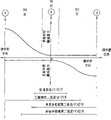
Fig. 5 is the performance diagram of the damping force of representational bumper SA shown in representative graph 3 and 4 with respect to piston velocity;
Fig. 6 is a damping force coefficient feature diagram of curves corresponding to the damping force control area of each stage position of regulating control, this regulating control is contained in shown in Fig. 2 and 3 among the representational bumper SA, links to each other with a stepping motor according to the rotation work of typical pulse (stepping) motor;
Fig. 7 A, 7B and 7C are the cross-sectional cutaway view of cutting open along K-K line among Fig. 4, represent the main portion of typical bumper SA shown in Figure 4;
Fig. 8 A, 8B and 8C sectional elevation, the main portion of typical bumper SA shown in the representative graph 3 and 4 for cutting open along L-L among Fig. 4 and M-M line;
Fig. 9 A, 9B and 9C sectional elevation, typical bumper SA main portion shown in the representative graph 3 and 4 for cutting open along N-N line among Fig. 4;
Figure 10 is the damping force characteristic diagram of curves when the relative piston of typical bumper SA extension stroke side shown in Figure 4 (phase place) is in the damping force hardware features;
Figure 11 is the damping force characteristic diagram of curves when stretching, extension and compression stroke side (phase place) all are in soft damping force state;
The damping force characteristic diagram of curves of Figure 12 when being in hard damping force state when compression stroke side (phase place);
Figure 13 is the square circuit diagram according to the signal processor in the suspension damping force control setup among first kind of embodiment of the present invention shown in Figure 1, and wherein the control signal of Chan Shenging uses for each bumper;
Figure 14 is according under first kind of embodiment situation of the present invention, the operational flowchart of carrying out in a control unit;
Figure 15 A, 15B, 15C, 15D is the time chart that comprehensively becomes together with 15E, and the damping force characteristic control operation situation of control unit in the first embodiment of the invention is shown;
Figure 16 A, 16B, 16C, 16D and 16E illustrate the formation state of control signal in the signal conditioning shown in Figure 13;
Figure 17 A, 17B and 17C are several time charts, in order to explain under the first embodiment situation shown in Fig. 1 to 16E and the excessive and not enough state of control effort that obtains under the Comparative Examples situation;
Figure 18 A, 18B and 18C are the time chart that combines, and in order to explain under first embodiment and Comparative Examples (Figure 18 C) situation, act on the duty ratio of corresponding stepping motor between a driving and hold mode;
Figure 19 A, 19AA, 19B, 19BB and 19C are several signal time charts, are illustrated in the various analog results under first embodiment and the Comparative Examples situation;
Figure 20 A and 20B are two performance diagrams, and representative forms the inverse ratio illustration of processing signals again under a kind of alternative situation of first embodiment.
Below referring to each accompanying drawing, so that better understand the present invention.
(first embodiment)
Fig. 1 illustrates the overall system structure figure of a kind of damping force characteristic of vehicular suspension system control setup that provides according to first kind of preferred embodiment of the present invention.
4 bumper SA
FL, SA
FR, SA
RLAnd SA
RRBe contained in the giving between the certain portions of given partial sum corresponding wheel (tire) (non-suspended mass) of car body (suspended mass) respectively, it should be noted, left wheel side (part) before the footnote FL representative, right wheel side (part) before the FR representative, FL represents back left wheel side (part), RR represents back right wheel side (part), and because all bumpers all have identical in essence structure, therefore representational bumper is only represented with SA simply.Wheel comprises the preceding left wheel of vehicle, preceding right wheel, the right wheel of back left wheel and back.Should also be noted that above-mentioned car body refer to for the certain portions system before a left side and preceding right wheel part and a left side, back and after right wheel part.
As shown in Figure 1, (vertical, promptly up and down) acceleration/accel (G; Gravity) sensor 1 (1
FL, 1
FR, 1
RR, 1
RL) be contained in respectively and a preceding left side and preceding right wheel side and a left side, back and the adjacent given car body part of back each bumper SA of right wheel side, each sensor is in order to the suspended mass normal acceleration (G) of detection effect on suspended mass (car body).
Each stroke sensor (2
FL, 2
FR, 2
RR, 2
RL) be contained between the corresponding car body partial sum corresponding wheel part, each stroke sensor 2 all is used for the relative velocity between definite suspended mass and non-suspended mass.Each stroke sensor 2 is to control unit 4 outputs one relative displacement signal H, to determine the relative velocity between suspended mass and non-suspended mass.
Fig. 2 illustrates the square circuit diagram of the vehicle shock absorber damping force control setup that provides according to first kind of embodiment of the present invention shown in Figure 1.
Referring to Fig. 1 and 2, control unit 4 is installed in the part of close driver's seat on the car body.This control unit 4 comprises: an input interface 4a; One CPU (central processing unit) 4b; One has a memory device 4bb and the RAM (random access memory) of ROM (read-only memory (ROM)); One output interface 4aa and actuator driver 4c; With a common bus.
Subsequent Fig. 3 illustrates the sectional elevation of each bumper SA shown in Fig. 1 and 2.
As shown in Figure 3, bumper SA comprises: cylinder barrel 30, (movable) piston 31, and it limits a upper chambers A and a lower chamber B; One overcoat 33, wherein the outer circumferential side at this cylinder barrel 30 forms a liquid storage cylinder 32; One bottom 34, it limits above-mentioned lower chamber B and liquid storage cylinder 32; One guide 35, it is a piston rod 7 slide-and-guides, the other end of this piston rod 7 connects above-mentioned moveable piston 31; One pendulum spring 36 is contained between this overcoat 33 and the car body; With a rubber draft gear 37.
Each stepper motor 3 shown in Fig. 1 and 2 is contained in the top of one of corresponding bumper SA shown in Figure 3, operationally rotates a regulating control 40 (referring to Fig. 4) with the rotating drive signal that sends in response to a corresponding actuator driver (circuit) 4c by a control stalk 70.
The rotating shaft of one of corresponding stepper motor 3 mechanically links to each other with corresponding regulating control 40 among each bumper SA by control stalk 70.
Fig. 4 illustrates the piston element 31 of each bumper SA and the amplification sectional elevation of the part of part on every side thereof.
As shown in Figure 4, this piston 31 is formed with through hole 31a and 31b.In addition, this piston be provided with compression phase dash pot valve 20 and stretching, extension mutually dash pot valve 12, two valves 20,12 open and close corresponding through hole 31a and 31b respectively.Single suspension mast 38 is in a spiral manner with 41 engagements of a spacing course setter and fix on it, and this course setter 41 is in a spiral manner with the small end engagement of piston rod 7 and fix on it.
In addition, extension stroke side (phase) check valve 17 also is contained in the periphery of this single suspension mast 38 with compression (or contraction) stroke side (compression mutually) check valve 22, and they flow through above-mentioned each runner that is formed by intercommunicating pore 39 according to the flow direction permission or the prevention fluid of fluid.As shown in Figure 3, this regulating control 40 by a corresponding actr (stepper motor) 3, by control stalk 70, can rotate.
It should be noted that this single suspension mast 38 is formed with the 4th aperture 14, the 3rd aperture 18,, 21, one second aperture 13,, one first aperture and the 5th aperture 16 by from top to bottom order respectively.
On the other hand, referring to Fig. 4, regulating control 40 is formed with a hollow parts 19, one first transverse holes 24 and one second transverse holes, 25, two transverse holes communicate the internal and external parts of regulating control 40.One longitudinal slot 23 is formed on an outer peripheral portion.Therefore, when showing as the stretching, extension phase time, piston stroke between upper chambers A and lower chamber, forms 4 runners as fluid flowing passage; Promptly 1) extension stroke side (phase) first flow D makes fluid pass through the inboard of the open valve of through hole 31b, extension stroke side (phase) dash pot valve 12, and arrives lower chamber B; 2) an extension stroke side (phase) the second runner E, fluid flow through second aperture 13, longitudinal slot 23, the 4th hole 14, extension stroke side (phase) dash pot valve 12 outer circumferential side of open valve within it, and arrive lower chamber B; 3) an extension stroke side (phase) the 3rd runner F, fluid flows through second aperture 13 within it, longitudinal slot 23 and the 5th aperture 16; With 4) a bypass flow channel G, fluid flows through the 3rd aperture 18, the second transverse holes 25 and hollow parts 19 within it, and arrives lower chamber B.
In addition, three fluids that during the compression stroke side (phase) of piston 31 fluid is flow through flow through passage, comprising: 1) compression stroke side (phase) first flow H, fluid flow through the open valve of through hole 31a and compression stroke side (mutually) dash pot valve 20 within it; 2) a compression stroke side (phase) the second runner J, fluid flow through hollow parts 19, the first transverse holes 24, the first apertures 21 within it, with compression stroke side (mutually) check valve of having opened 22, and arrive upper chambers A; With 3) bypass flow channel G, fluid flows through hollow parts 19, the second transverse holes 25 and the 3rd aperture 18 within it.
In brief, this bumper SA arranges and is constructed to and can as shown in Figure 5, carries out multistage damping force characteristic conversion in its damping behavior curve ranges when described regulating control 40 rotates with the rotation of corresponding stepper motor 3.
Fig. 6 illustrates with respect to extension stroke of piston 31 (phase) and compression stroke (mutually), the turned position of regulating control 40 and the relation between the damping force characteristic.
More particularly, as shown in Figure 6, the basic midway location that all is in soft damping force characteristic position (hereinafter referred to as soft district SS) mutually from its stretching, extension and compression when regulating control 40 is when given anticlockwise direction rotates, the damping force coefficient of extension stroke side (phase) can be from maximum hardware features to minimum hardware features with multistage variation, the damping force coefficient of compression stroke side then is fixed on a software feature position (hereinafter referred to as extension stroke side hard area HS).On the contrary, when regulating control 40 in the middle of it position when given clockwise direction rotates, the damping force coefficient of compression stroke side (phase) only can then be fixed on software feature position (hereinafter referred to as the compression hard area) at the damping force characteristic of compression stroke side from maximum hardware features to minimum hardware features with the multistage hard area that is converted to.
As shown in Figure 6, when 1. regulating control 40 goes to the position, 2. and 3. during arbitrary position, along K-K among Fig. 4, L-L, the cross-sectional plane of the piston assembly each several part that M-M and N-N line are cut open is illustrated respectively in Fig. 7 A (1.), 7B (2.) and 7C (3.) (K-K), Fig. 8 A (1.), 8B (2.) and 8C (3.) (L-L, M-M), Fig. 9 A (1.) is among 9B (2.) and the 9C (3.).
Relevant position shown in Figure 6 1., 2. and damping force characteristic 3. be shown in Figure 10 respectively, in 11 and 12.
Figure 10 illustrates when regulating control 40 and is arranged in Fig. 6 position 1. the time, the damping force characteristic of typical bumper SA.
Figure 11 illustrates the damping force characteristic that regulating control 40 is arranged in Fig. 6 SA 2. the time.
Figure 12 illustrates the damping force characteristic that regulating control 40 is arranged in Fig. 6 SA 3. the time.
Subsequent, Figure 14 illustrates the operational flowchart of the damping force characteristic content of operation of explaining that control unit 4 carries out each bumper SA.
During step 11, CPU 4b judges whether formed control signal V (to each bumper SA) increases and surpasses predetermined positive thresholding δ
T(it should be noted in this first kind of embodiment δ
T=0).If step 101 is judged as be, program proceeds to step 102, a corresponding bumper SA is placed stretch phase hard area HS.
If step 101 is judged as non-, then program proceeds to step 103, and CPU4b judges whether control signal V is lower than predetermined negative thresholding-δ
C(it should be noted, in first kind of embodiment, should-δ
CAlso be 0).
If what step 103 was judged is that then program proceeds to step 104, and a corresponding bumper SA is placed compression phase hard area SH.
If step 103 is judged as non-, then program proceeds to step 105, if promptly CPU4b determines that control signal V value falls into from+δ
TTo-δ
CBetween the value, be zero, then a corresponding bumper SA placed separately stretching, extension and the mutually soft district SS of compression.
Figure 15 A to 15E illustrates the time chart that combines, to explain control unit 4 under first kind of embodiment situation and the operation of one or more bumper SA.
At first, when control signal (V) is shown as zero, each bumper SA press Figure 14, and soft mode SS controls shown in 15A and the 15D.
When according to suspended mass vertical speed Δ X ' and relative velocity (Δ X '-Δ X '
o) the control signal V that forms changes shown in Figure 15 A in time and this control signal is shown as timing, each bumper SA is by stretching phase hard area HS control, at this moment compression fixes a predetermined low damping force position, changes mutually so that hardware features (target damping force characteristic position P to be provided and stretch
T), the value of it and control signal V is in direct ratio.
On the other hand, if the direction of control signal V (and is lower than the thresholding-δ of predetermined negative for negative
C=0), then provides compression phase hard area SH, make stretching, extension phase damping force characteristic be fixed on low predetermined damping force characteristic position, and compression phase damping force characteristic changes, so that a target damping force characteristic position P to be provided
C, the value of it and control signal V is in direct ratio.
Conversion operations between the mode (HS, SH and SS) will illustrate in conjunction with Figure 15 A to 15E.
Symbol a representative among Figure 15 C is according to suspended mass vertical speed Δ X ' and relative velocity (Δ X '-Δ X '
o) direction of the control signal V that forms by negative value (downwards) to a zone of changing on the occasion of (making progress).
In regional a, relative velocity (Δ X '-Δ X '
o) negative value (phase place of bumper SA is in the compression phase) still is provided, like this, corresponding bumper SA is controlled in stretching, extension phase hard area HS according to the direction of control signal V, and the phase place of corresponding bumper SA is in the stretching, extension phase.Therefore, at regional a, this stretching, extension that the piston 31 of bumper SA has left provides and the directly proportional hardware features of the value of control signal V mutually.
Zone b represents a zone, and wherein the direction of control signal V (discriminating direction signal) still is just (value that makes progress), and relative velocity (Δ X '-Δ X '
o) from negative value to changing on the occasion of (the stretching, extension phase that the piston of corresponding bumper SA has left).At this moment, owing to the direction of bumper SA according to control signal V, to stretch the mode Be Controlled of phase hard area HS, the stroke directions of corresponding bumper SA is for stretching phase.Therefore, at regional b, the stretching, extension of bumper SA provides the directly proportional hardware features with control signal V mutually.
Zone c represents a zone, and wherein control signal V is from changing to negative value (downwards) on the occasion of (making progress).Yet at this regional c, because corresponding bumper SA is controlled to compression phase hard area SH according to the direction (discriminating direction signal) of control signal V, this zone c provides such phase place (at this regional c, stretch phase), move with soft (predetermined low damping force characteristic) characteristic at the piston of the corresponding bumper SA of this phase place.
Zone d represents a zone, and wherein control signal V still is a negative value (downwards), and relative velocity (Δ X '-Δ X '
o) from the occasion of changing to negative value (be positioned at stretch the phase side at the piston of the corresponding bumper SA of this phase place).At this moment, because corresponding bumper SA is controlled in compression phase hard area SH according to the direction of control signal, therefore the stroke (phase) of corresponding bumper is positioned at the compression phase.At this regional d, the piston of bumper SA provides and the directly proportional hardware features of the value of control signal V mutually in the compression of its passive movement.
The as above explanation of being done in conjunction with Figure 15 A to 15C is when according to suspended mass vertical speed Δ X ' and relative velocity (Δ X '-Δ X '
o) when definite control signal V had the direction mutually the same with the discriminating direction symbol (regional b and d), the instantaneous phase that the piston of bumper SA moves was controlled in the hardware features mode.If their (V and Δ X '-Δ X '
o)) mutual meeting differ from one another (regional a and c), this phase place that the piston of then corresponding bumper SA has moved is controlled by software feature.In this first kind of embodiment, realized according to of the control of sky Hook theory to damping force characteristic.
In first embodiment, that when the phase place termination that the piston of a corresponding bumper SA moves constantly, promptly when the zone from regional a to regional b conversion with from the moment of regional c to regional d (hardware features is to software feature) conversion, damping force characteristic position P
TOr P
CBe in such phase place, i.e. the control of being carried out is to this phase transition, and this phase place has converted the hardware features side at above-mentioned zone a and c place to.So under not free situation about lagging behind, finish to the conversion of hardware features from software feature.
Subsequent, Figure 13 illustrates a structure in order to the signal processor that forms control signal V, by this control signal V, according to desirable sky Hook theory, according to suspended mass vertical speed Δ X ' and relative velocity (Δ X '-Δ X '
o), produce control effort F, even adopt stepper motor 3 also can obtain promising result as actr (such actr has lower response characteristic so that can not the resonant frequency of non-suspended mass be responded).It should be noted that signal processor shown in Figure 13 is for each bumper SA.
Should also be noted that this control unit 4 is according to corresponding 4 suspended mass normal acceleration sensors 1 (1
FL, 1
FR, 1
RLWith 1
RR) output with front and back and preceding left wheel side bumper SA
FL, SA
FRAnd the vertical acceleration signal of the adjacent car body of the right wheel side bumper in a back left side and back obtains is 4 wheel side suspended mass normal acceleration G
FL, G
FR, G
RLAnd G
RR
Should also be noted that vehicle roll acceleration/accel G
RCan be according to following formula (5), by the preceding right side and preceding left wheel side vertical hanging mass acceleration signal G
FLAnd G
FRObtain.
G
R=(G
FR-G
FL)/2 ……(5)
At the first square B1,4 pairs 4 wheel side suspended mass normal accelerations of control unit G
FL, G
FR, G
RLAnd G
RRAnd roll acceleration G
RIntegration or make them pass through a low-pass filter is with each acceleration signal G
FLTo G
RConvert to respectively suspended mass vertical speed Δ X ' (or V ') (V '
-FL, V '
-FR, V '
-RLAnd V
-RR) and rolling velocity V
R
At this square B1, control unit 4 can be carried out a bandpass filter and handle, and to improve the isolating power to those outer component of signals of target frequency band, then will carry out damping force characteristic control in the target frequency band.That is to say that one first bandpass filter and one second bandpass filter are isolated the interior angular oscillation speed signal V of angular oscillation resonant frequency band scope of vehicle hanging quality
BFR, V
BFL, V
BRRAnd V
BRLIn addition, one the 3rd bandpass filter can obtain to have the rolling velocity signal of a vehicle roll resonant frequency band, as an expected value (center).
In square B1 place, angular oscillation factor alpha
fAnd α
rCan set independently of each other the angular oscillation of front vehicle wheel side and rear wheel side, so that can be according to the difference on vehicle front vehicle wheel side concrete parameter (weight, spring constant etc.) the simulating vehicle status values different with rear wheel side place.
At square B1 place, rolling coefficient r
fAnd r
rCan independently set preceding vehicle side and rear wheel side, so that can not become not enough owing to act on the required control effort of the vehicle-state along the rolling direction of external force (transverse acceleration) generation on the car body in the opposing Vehicular turn driving process.
At square B1 place, this control unit 4 also can calculate 4 suspended mass sub-signal V
H(V
FR-LH, V
FL-LH, V
RR-RH, V
RL-LH):
Preceding right wheel side:
V
FR-RH=α
f·V
BFR+r
f·V
R ……(6)
Preceding left wheel side:
V
FL-LH=α
f·V
BFL-r
f·V
R ……(7)
The right wheel side in back:
V
RR-RL=α
f·V
BRR+r
r·V
R ……(8)
Back left wheel side:
V
RL-LH=α
f·V
BRL+r
r·V
R ……(9)
On the other hand, as shown in figure 13, at square B2 place, this control unit 4, by for example being contained in one or more differentiators or the high-pass filter of square B2, the relative displacement signal H that each corresponding stroke sensor 2 is transmitted converts each relative velocity (the Δ X '-Δ X ' between suspended mass and non-suspended mass respectively to
o) { (Δ X '-Δ X '
o)
FL, (Δ X '-Δ X '
o)
FR, (Δ X '-Δ X '
o)
RL, (Δ X '-Δ X '
o)
RR.
Referring to Figure 13,, as shown in figure 16, form one respectively and stretch phase processing signals XP ' at one square B3 place, back
TCompress processing signals XP ' mutually with one
CThat is to say, detect positive negative peak respectively as each relative velocity signal (Δ X '-Δ X ' according to the discriminating direction symbol of relative velocity signal (stretch the phase side for just, compression phase side is for bearing)
o) stretching, extension phase peak value XP
TWith compression peak value XP mutually
C, and till they are remained to the peak value that detects the back respectively, stretch mutually and compress processing signals XP ' mutually thereby form respectively thus
TAnd XP '
C
At back one square B4, formation and stretching, extension be processing signals XP ' mutually
TInversely proportional stretching, extension phase is processing signals KUS again
-T(KUS
-FR-T, KUS
-FL-T, KUS
-RR-T, KUS
-RL-T) with compression processing signals XP ' mutually
CInversely proportional compression phase is processing signals KUS again
-C(KUS
-FR-C, KUS
-FL-C, KUS
-RR-C, KUS
-RL-C).
That is to say, stretch mutually processing signals KUS again
-TWith compression processing signals KUS mutually
-CCan obtain by following formula:
KUS
-T=1/XP '
T(10) and
KUS
-C=1/XP′
C ……(11)。
It should be noted, if stretch phase processing signals XP '
TWith compression processing signals XP ' mutually
CIn each be equal to or less than a minimum value MIN (XP '
T, XP '
C≤ MIN), then carry out such processing: the stretching, extension or the compression phase processing signals that will be equal to or less than predetermined minimum value MIN place a predetermined maximum (KUS
-T, KUS
-C=MAX (1.0,0.9)).Carry out this processing in order that prevent to stretch phase or compress phase processing signals value KUS again
-TOr KUS
-COwing in formula (10) or (11), serve as each processing signals XP ' of denominator
T, XP '
CValue can show when approaching zero and be tending towards infinitely great.
It should be noted that the final step of square B4 can be to stretching mutually processing signals KUS again
-T(KUS
-FR-T, KUS
-FL-T, KUS
-RR-T, KUS
-RL-T) with compression processing signals KUS mutually
-C(KUS
-FR-C, KUS
-FL-C, KUS
-RR-C, KUS
-RL-C) average, to obtain through asking average stretching, extension processing signals KSU ' mutually
-T(KUS '
-FR-T, KUS '
-FL-T, KUS '
-RR-T, KUS '
-RL-T) with through asking average compression processing signals KUS ' mutually
-C(KUS '
-FR-C, KUS '
-FL-C, KUS '
-RR-C, KUS '
-RL-C).
At square B5, this control unit 4 is according to the suspended mass sub-signal V of following formula (12) to (15) or (16) and (12) ' to (15) ' or (16) ' drawn by the suspended mass vertical velocity signal Δ X ' that forms according to square B1 place
HWith by the relative velocity signal that forms according to square B1 place (Δ X '-Δ X '
o) (through average) stretching, extension of drawing mutually and compress mutually processing signals KUS ' again
-TAnd KUS '
-C(or replace with without average KUS
-TAnd KUS '
-C), obtain control signal V and (stretch phase control signal V
FR-T, V
FL-T, V
RR-T, V
RL-TWith compression control signal V mutually
FR-C, V
FL-C, V
RL-C, V
RR-C).
Preceding right wheel side:
V
FR-T=g
f·V
FR-RH·KUS′
-FR-T ……(12)
V
FR-C=g
f·V
FR-RH·KUS′
-FR-C ……(12)′
Preceding left wheel side:
V
FL-T=g
f·V
FR-LH·KUS′
-FL-T ……(13)
V
FL-C=g
f·V
FR-LH·KUS′
-FR-C ……(13)′
The right wheel side in back:
V
RR-T=g
r·V
RR-RH·KUS′
-RR-T ……(14)
V
RR-C=g
r·V
FR-RH·KUS′
-FR-C ……(14)′
Back left wheel side:
V
RL-T=g
r·V
RL-LH·KUS′
-RL-T ……(15)
V
RL-T=g
r·V
RL-LH·KUS′
-RL-C ……(15)′
G wherein
fThe total ride gain of expression front vehicle wheel side damping force, and g
rThe total ride gain of expression rear wheel side damping force.
It should be noted that this control signal V also can be obtained by following formula: V=g Δ X ' KUS
-T(16) and V=g Δ X ' KUS
-C(16) '.
That is to say that in this embodiment, at square B4 shown in Figure 13 place, this stretches phase processing signals XP '
TWith compression processing signals XP ' mutually
CThe quality that is draped vertical velocity signal V
-RHMultiply each other with such form, make this stretching, extension phase processing signals XP '
TWith compression processing signals XP ' mutually
CStretch mutually processing signals KUS ' again in case be converted into
-TWith compression processing signals KUS ' mutually
-CAfter, they respectively with corresponding stretching, extension processing signals XP ' mutually
TWith compression processing signals XP ' mutually
C(average with it in addition form) is inversely proportional, avoids control signal to be removed by zero.
In addition, in the process that forms control signal V, relative velocity signal (Δ X '-Δ X '
o) each peak value be separately according to stretching phase side (positive side) and compression side (minus side) detection mutually, the peak value XP of the place phase side consistent with the discriminating direction symbol of suspended mass vertical speed Δ X
T, XP
CBe used.Therefore, shown in Figure 16 C, this stretches phase and compresses processing signals XP ' mutually
TAnd XP '
CCan obtain by the low frequency state.Thereby, can form control signal V, to show a low frequency state.
Show as square B4 place, can be to stretching mutually processing signals KUS again
-TWith compression processing signals KUS mutually
-CAverage, control signal V is formed with lower frequency state.
Subsequent Figure 16 A to 16E illustrates a time chart that combines, in order to the situation of explaining that control signal forms in the signal processor shown in Figure 13.
In this case, suppose that suspended mass vertical speed Δ X ' changes in time with lower frequency version shown in Figure 16 A, and relative velocity (Δ X '-Δ X '
o) change in time with upper frequency shown in Figure 16 B (solid line among Figure 16 B) form.
Shown in each stain of Figure 16 C (each point that provides), high frequency relative velocity (Δ X '-Δ X '
o) middle each the sampled peak value XP of phase (positive side) that stretches
TWith compression (minus side) each sampled peak value XP mutually
CDetected and remain to till next peak value is detected.Therefore, each high frequency relative velocity (Δ X '-Δ X '
o) be converted into the stretching, extension phase processing signals XP ' of lower frequency
TWith compression processing signals XP ' mutually
C
Thereby as formula (12) to (15) and formula (12) ' show to (15) ' (or (16) and (16 ')), the variation waveform of the control signal V that calculates according to above-mentioned low frequency signal also obtains with lower frequency waveform such shown in Figure 16 D.Like this, even the response characteristic of corresponding stepper motor 3 is less high, the conversion of damping force characteristic position P still can change with the control signal V shown in Figure 16 E.
Above-mentioned operation in conjunction with Figure 16 A to 16E will illustrate in greater detail in conjunction with each time chart of Figure 17 A to 17C.
It should be noted, solid line representative among Figure 17 A to 17C is with respect to the control signal in the comparative example of the present invention, long and short dash line is represented the damping force characteristic position P in this comparative example, and dotted line is represented control signal V and damping force characteristic position P among first embodiment respectively.
At first, Figure 17 A illustrates a kind of situation, wherein relative velocity (Δ X '-Δ X '
o) the peak value XP of stretching, extension phase side
TBecome a smaller value by a higher value.At this moment, because according to the control signal of this comparative example with the high-frequency range variation, actr is to the switching hysteresis of damping force characteristic position P in the corresponding stepper motor 3, control effort can not reduce ideally, thereby the excessive a part of control effort of performance control effort occurs, this represents with each left oblique line in Figure 17 A.On the other hand, according to the control signal V under the first embodiment situation, the expression control effort of representing with right oblique line is excessive and all occurred with the expression control effort insufficient section that horizon is represented.
Subsequent, Figure 17 B illustrates a kind of situation, wherein relative velocity (Δ X '-Δ X '
o) at the peak value XP that stretches phase
TBecome higher value by smaller value successively.
At this moment, according under the situation of comparative example, control signal changes at high frequency region, because the switching hysteresis of damping force characteristic position P in the corresponding stepper motor 3, control effort can not reduce ideally, like this, the excessive control effort part shown in the oblique line of Figure 17 B left side occurred under the situation of comparative example.On the other hand, under the situation of first embodiment, the control effort insufficient section of representing with horizon among Figure 17 B has appearred.
In the situation shown in Figure 17 C, relative velocity (Δ X '-Δ X '
o) peak value that stretches the phase side do not change.
At this moment, according to the control signal under the comparative example situation (V), the excessive control effort part of the control effort shown in the left oblique line appears.Yet according to the control signal V among first embodiment, the control effort insufficient section that horizon is represented among Figure 17 C appears.
As mentioned above, even the such excessive or not enough situation of control effort of Figure 17 A to 17C has taken place in first embodiment, but compare with the situation of comparative example, the area (=energy) of each control effort part reduces, like this, is difficult to occur the excessive trend of control effort.This result can clearly obtain authentication in the analog result of Figure 19 A to 19B.
Figure 19 A and 19B illustrate the target location ACTR of one of corresponding stepper motor 3 of actual suspension quality normal acceleration and according to the time chart of the actual position of one of corresponding stepper motor 3 of first embodiment simulation.
Figure 19 AA, 19BB and 19C illustrate the target location ACTR of actual suspension quality normal acceleration one of corresponding stepper motor under the comparative example situation and the time chart of actual position.
Shown in Figure 19 A to 19C, although owing in comparative example (especially referring to Figure 19 C), produced excessive control effort with the signal shown in the oblique line, big distortion appears in the signal waveform of actual acceleration, but under the situation of first embodiment, corresponding distortion but is difficult to appear in the signal waveform of actual suspension quality normal acceleration.
It should be noted, in Figure 16 A to 16E, meet corresponding each oscillating action district of each several part that S represents, wherein suspended mass vertical speed Δ X ' (because phase is stretched in positive sign "+" representative) and relative velocity (Δ X '-Δ X ' with black matrix
o) discriminating direction of (because negative sign " " representative compression phase) meets inconsistent each other.At this moment, because the effect of mutually anti-phase (compression phase) predetermined low damping force characteristic, the damping force characteristic position P of controlled phase (stretching, extension phase) does not need to carry out the variable control of damping force characteristic as doing under the comparative example situation.Therefore, because the driving to one of corresponding stepper motor 3 is left in the basket at each oscillating action district S, the driving response characteristic of 3 couples of control signal V of each stepper motor can be guaranteed as mentioned above like that, and the driving of each stepper motor 3/maintenance duty ratio can significantly reduce.
That is to say that Figure 18 A to 18C illustrates control signal (solid line) under the comparative example situation and the damping force characteristic position (long and short dash line) under the comparative example situation.In this embodiment, the driving of one of corresponding stepper motor 3/maintenance duty ratio is shown as 30% to 50%.Yet in last example, the numerical value of duty ratio is under the minimum.If it is bigger that the amplitude of control signal becomes, because stepper motor 3 responses untimely (hysteresis), above-mentioned duty ratio will show as near 100%.
In addition, with regard to stepper motor 3 minimum response characteristics, require in such time cycle semiperiod of quite non-suspended mass resonant frequency, to finish and once stretch between phase hard area HS and the soft district SS or the round driving response characteristic between compression phase hard area SH and the soft district SS.For example, the resonant frequency of supposing non-suspended mass is 10HZ, then requires to finish in 25 milliseconds the driving that once comes and goes form.
On the other hand, under the situation of first embodiment, if stretch relative velocity (the Δ X '-Δ X ' of phase
o) peak value XP
TDo not change, then the driving of stepper motor 3/maintenance duty ratio shown in Figure 18 A (dotted line), is shown as 0%.In addition, shown in Figure 18 B, even stretch phase peak value XP
TChange, described driving/maintenance duty ratio also only is shown as near 50%.
In addition, with regard to the minimum response characteristic of stepper motor 3,, promptly detect between the next peak period in the cycle at the resonant frequency of non-suspended mass, only need with stretch between phase hard area HS and soft district SS or compression mutually the form that once comes and goes between hard area SH and soft district SS drive and get final product.For example, if the resonant frequency of non-suspended mass is 10Hz, only need in 100 milliseconds, to finish once to come and go to drive.
As mentioned above, the suspension damping force control setup among first embodiment has following advantage:
(1) even adopt the cheap stepper motor that consequently can not respond to the resonant frequency of suspended mass than low responsive characteristic, also might be according to the theoretical control effort that produces of desirable sky Hook;
(2) because the driving/maintenance duty ratio of each stepper motor 3 can not increase, can not cause the increase of stepper motor 3 consumption of power and the minimizing of durability;
The following describes other several preferred embodiments according to suspension damping force control setup of the present invention.Because in described other embodiment, the content of signal processor is different from first embodiment in control unit 4, all the other structures are identical with the situation of first embodiment, therefore only explain and the variant point of first embodiment.
(second embodiment)
In second preferred embodiment, suspension damping force control setup includes following signal processor.
In the square B3 of Figure 13, stretch phase processing signals XP '
TWith compression processing signals XP ' mutually
CForm in the same manner as in the first embodiment respectively.Yet after this, control signal V is to be proportional to instantaneous suspended mass sub-signal V
HValue divided by with this suspended mass sub-signal V
HDiscriminating direction meet that consistent phase processing signals (XP '
TOr XP '
C) in the mode of arbitrary signal form, that is:
V=gV
H/ XP '
T(17), or
V=g·V
H/XP′
C ……(18)
(or do not adopting instantaneous suspended mass sub-signal V
HSituation under,
V=g1/XP '
T(17) ' or
V=g·1/XP′
C ……(18)′)
(the 3rd embodiment)
In the third preferred embodiment, include following signal processor (circuit) in the control unit 4 of suspension damping force control setup.
In the same manner as in the first embodiment, obtain a relative velocity (Δ X '-Δ X ' at the square B2 of Figure 13
o).Afterwards, this relative velocity (Δ X '-Δ X '
o) the absolute value XP of positive negative peak
T, CBe detected and remain to the absolute value of back one peak value measured till, to form processing signals XP '
T, CProcessing signals together with forming forms control signal V by following formula, it and instantaneous suspended mass sub-signal V
HDivided by this processing signals XP '
T, CValue in direct ratio:
V=g·V
H/XP′
T,C ……(19)
(perhaps, the replacement situation that second embodiment is such is not obtained V
H,
V=g·1/XP′
T,C ……(19)′)。
Can obtain in described stretching, extension phase control signal and compression nonseptate control between the control signal mutually.
(the 4th embodiment)
In the suspension control setup that provides according to the 4th kind of preferred embodiment of the present invention, control unit 4 is provided with following signal processor (circuit).
At the square B2 place of Figure 13, obtain a relative velocity (Δ X '-Δ X ' in the same manner as in the first embodiment
o).Afterwards, measure this relative velocity (Δ X '-Δ X '
o) the absolute value XP of peak value
T, C, and remain to the absolute value of measuring next peak value, to form processing signals XP '
P, CForm then one with this processing signals XP '
T, CThe inversely proportional KUS of processing signals again
-T, CForm control signal by following formula (20 and 21) at last, it and instantaneous suspended mass sub-signal V
HMultiply by this processing signals KUS again
-T, CValue in direct ratio:
KUS
-T, C=1/XP '
T, C(20) and
V=g·V
H·KUS
-T,C ……(21)
(perhaps, if do not form suspended mass sub-signal V
H, this formula (21) is used
V=gX ' KUS
-T, C(21) ' replace).
(the 5th embodiment)
Among the 5th kind of embodiment according to suspension damping force control setup of the present invention, obtain average stretching, extension phase peak value XP by the method for second embodiment
T-nWith average compression peak value XP mutually
T-nThen mutually and compress peak value (XP mutually according to the average stretching, extension of described warp
T-n, XP
C-n), form stretching, extension processing signals XP ' mutually by following formula (22) and (23)
T-nWith compression processing signals XP ' mutually
C-n:
XP
T-n=(α·XP
T(n)+β·XP
T(n-1)+γP
T(n-2)+η·XP
T(n-3)×(1/(α+β+γ+η) ……(22)
XP
C-n=(α XP
C (n)+ β XP
C (n-1)+ γ P
C (n-2)+ η XP
C (n-3)* (1/ (alpha+beta+γ+η) ... (23) n is an integer in formula (22) and (23), and α, beta, gamma and η are coefficient of weight.
(other alternatives)
For example, although in the various embodiments described above, 4 suspended mass G sensors 1 (1
FL, 1
FR, 1
RLAnd 1
RR) be the car body position of the left and right wheel of left and right wheel side and back before being contained in, but the quantity of installation site is random.The system that can be used for only being equipped with single suspended mass G sensor according to suspension damping force control setup of the present invention in the front vehicle wheel side.
In addition, although among above-mentioned first and second embodiment, stretch mutually processing signals KUS again with inverse proportion function (10) and (11) formation
-TWith compression processing signals KUS mutually
-C(they respectively with stretch processing signals XP ' mutually
TWith compression processing signals XP ' mutually
CInversely proportional), but also can correspondingly adopt square B4 among Figure 13 and the inverse ratio illustration among Figure 20 A and the 20B.
At last, above-mentioned formula (13) to (16) and (13) ' to (16) ' in for deriving the front and back wheel side control gain g of control signal V
fAnd g
rAlso can carry out conversion (it should be noted the available speed of a motor vehicle conversion of representing with g of gain) according to the speed of a motor vehicle that the car speed sensor shown in Fig. 2 (being represented by dotted lines) measures.
Claims (24)
1. device that is used for vehicle suspension system, described suspension have the dampening arrangement that is contained between the non-suspended mass that one of the suspended mass that is made of car body and corresponding wheel constitute, and described device comprises:
A) damping force characteristic converting means, it responds to driving command, and in order to the damping force characteristic of arbitrary phase place in the stretching, extension of the described dampening arrangement of conversion or the compression mutually, and another phase place in its stretching, extension or compression mutually provides low damping force characteristic;
B) first detecting device in order to detecting the state as the car body of suspended mass, and is exported first signal that characterizes this car body state;
C) rate switching device is converted to a secondary signal that characterizes the suspended mass vertical speed of described suspended mass in order to first signal with the output of described first detecting device;
D) second detecting device, in order to detecting the relative displacement between described suspended mass and non-suspended mass, and according to the displacement between suspended mass that records and non-suspended mass, output one characterizes the 3rd signal of relative velocity between suspended mass and non-suspended mass;
E) control signal forms device, in order to according to the secondary signal of described rate switching device output and the 3rd signal of described second detecting device output, forms and export a control signal;
F) control setup, in order to according to described control signal, control the damping force characteristic of described dampening arrangement by described damping force characteristic converting means, make the relative suspended mass of discriminating direction symbol when the secondary signal of described rate switching device output be shown as when making progress, the stretching, extension phase damping force characteristic of described bumper can be controlled with changing, be shown as when downward with the relative suspended mass of described discriminating direction symbol when described control setup, the damping force characteristic Be Controlled of compression phase, this control setup also comprise one be contained in described dampening arrangement in the low responsive characteristic actr that links to each other of described damping force characteristic converting means, and wherein said control signal forms device and forms a lower frequency section control signal, make the driving of the driving command of described actr being sent according to this control signal and keep duty ratio between order, when any variation not taking place, described control signal do not become less, even and bigger variation when taking place in described control signal, also become and have only half, like this, described actr just can be followed the variation of described control signal.
2. the device that is used for vehicle suspension system as claimed in claim 1, it is characterized in that described control signal forms device and comprises stretching, extension phase and compression processing signals formation device mutually, stretching the peak value of the 3rd signal of output mutually in order to detect described second detecting device, and the peak value that records remained to by it detect next peak value, and another peak value that detects described the 3rd signal of compression phase, and this another peak value that will record remains to and detects next another peak value, stretch the phase processing signals and compress processing signals mutually to form respectively, thereby the discriminating direction symbol detection according to described the 3rd signal of described second detecting device output goes out described peak value, and wherein said control signal forms that device forms and the described control signal of output with in direct ratio by a value of the secondary signal of described rate switching device output, this value for the value of secondary signal divided by with one of the mutually any processing signals acquisition of the corresponding to described stretching, extension of discriminating direction symbol of the described secondary signal of described rate switching device output and compression.
3. the device that is used for vehicle suspension system as claimed in claim 1, it is characterized in that described control signal forms device and comprises that processing signals forms device, absolute value in order to the peak value of described the 3rd signal that detects the output of described second detecting device, and this peak value absolute value remained to detect next peak value absolute value, to form a processing signals, and a value of the control signal that wherein said control signal formation device forms and the described secondary signal of described rate switching device output is in direct ratio, and this value is that second control signal obtains divided by described processing signals.
4. the device that is used for vehicle suspension system as claimed in claim 1 is characterized in that described control signal forms device and comprises:
Processing signals forms device with compressing mutually to stretch phase, in order to correspondingly to detect the peak value of the 3rd signal that stretches the output of second detecting device described in the phase, and the peak value of measuring remained to by it detect next peak value, and remain to by it in order to another peak value of the 3rd signal that correspondingly detects the compression phase and another peak value that will measure and to detect next another peak value, stretch the phase processing signals and compress processing signals mutually to form respectively; Described each peak value is according to the discriminating direction symbol detection of described the 3rd signal of described second detecting device output; With
Stretch and compression processing signals formation device again mutually, in order to form one with described stretching, extension mutually the inversely proportional stretching, extension of processing signals mutually again processing signals and one with the inversely proportional compression of described compression phase processing signals processing signals mutually, and wherein said control signal forms that device forms and the control signal of output with by the 3rd signal times of described second detecting device output with stretch mutually by consistent described of the discriminating direction symbol of the secondary signal of described rate switching device output or the compression phase again in the processing signals value of arbitrary signal acquisition in direct ratio.
5. the device that is used for vehicle suspension system as claimed in claim 1 is characterized in that control signal forms device and comprises:
Processing signals forms device, in order to the peak value absolute value of described the 3rd signal that detects described second detecting device output, and this peak value absolute value remained to by it detects next peak value absolute value, to form processing signals; With
Processing signals forms device again, in order to form one with the inversely proportional processing signals again of described processing signals, and the wherein said control signal described secondary signal that forms described control signal that device forms and the output of described rate switching device to multiply by a value of the described acquisition of processing signals more in direct ratio.
6. the device that is used for vehicle suspension system as claimed in claim 2, it also comprises stretches and compresses mutually processing signals formation device again, stretches and compress mutually processing signals (KUS again in order to form and to export
-TSignal KUS
-C), this is processing signals and the present maintained peak value (XP of representative again
T, XP
C) stretching, extension with the compression mutually processing signals (XP '
TAnd XP '
C) inversely proportional (KUX
-T=1/XP '
T, KUS
-C=1/XP '
C); And equilibration device, in order to average described stretching, extension and compression processing signals (KUS mutually
-T, KUS
-C), with produce with output through average stretching, extension and compression mutually again processing signals (KUS '
-T, KUS '
-C), described average stretching, extension with the compression mutually again processing signals offer described control signal generating means, to produce described control signal.
7. the device that is used for vehicle suspension system as claimed in claim 4, it also comprises equilibration device, in order to average described stretching, extension and compression processing signals (KUS mutually
-T, KUS
-C) with produce with output through average stretching, extension and compression mutually again processing signals (KUS '
-T, KUS '
-C), described average stretching, extension mutually and compress mutually again that processing signals offers described control signal generating means, to produce described control signal.
8. the device that is used for vehicle suspension system as claimed in claim 7 is characterized in that described control signal comprises that one stretches phase control signal (V
-T), it enters stretching, extension at described dampening arrangement and works relatively, compresses control signal (V mutually with one
-C) it enters the compression phase time at described dampening arrangement and works, described stretching, extension and compression mutually control signal all according to the secondary signal (Δ X) of described rate switching device output with through average stretching, extension and compression mutually again processing signals (KUS '
-T, KUS '
-C) produce and output.
9. the device that is used for vehicle suspension system as claimed in claim 8, it is characterized in that described dampening arrangement comprises 4 bumpers, they all have identical structure, and be positioned at a preceding left side, preceding right, a left side, back and right wheel position, back, and wherein said first detecting device comprises 4 suspended mass normal acceleration sensors and rate switching device, they are according to a left side before determining as each suspended mass acceleration signal of first signal that obtains from described each suspended mass normal acceleration sensor, preceding right, the right wheel side in a left side, back and back, the suspended mass normal acceleration.
10. the device that is used for the suspension of vehicle as claimed in claim 9, it comprises that also roll acceleration determines device, in order to according to front vehicle wheel side mounting quality normal acceleration (G
FL, G
FR), determine roll acceleration (G according to the following equation
R): G
R=(G
FL-G
FR)/2.
11. the device that is used for vehicle suspension system as claimed in claim 10 is characterized in that described suspended mass normal acceleration transfer device comprises a low-pass filter.
12. the device that is used for vehicle suspension system as claimed in claim 10 wherein also comprises: bandpass filter, in order to from the suspended mass normal acceleration that constitutes secondary signal and obtain from described rate switching device (V '
FR, V '
FL, V '
RL, V '
RR) in obtain angular oscillation speed signal (V with predetermined suspended mass angular oscillation resonant frequency band
BFR, V
BRL, V
BRL, V
BRR).
13. the device that is used for vehicle suspension system as claimed in claim 12 comprises also that wherein the suspended mass sub-signal determines device, in order to determine the suspended mass sub-signal (V of each control signal by following formula
H):
Preceding right wheel side:
V
FR-RH=α
f·V
BFR+r
f·V
R,
Preceding left wheel side:
V
FL-LH=α
f·V
BFL+r
f·V
R,
The right wheel side in back:
V
RR-RH=α
fV
BRR+ r
rV
RAnd
Back left wheel side:
V
RL-LH=α
f·V
BRL-r
r·V
R,
α wherein
fWith front vehicle wheel side mounting quality angular oscillation coefficient, α
rBe rear wheel side mounting quality angular oscillation coefficient, r
fBe front vehicle wheel side rolling coefficient, r
rBe rear wheel side rolling coefficient, and V
RBe the rolling sub-signal.
14. the device that is used for vehicle suspension system as claimed in claim 13 is characterized in that the preceding right side, a preceding left side, and the right and back left wheel side in back stretches mutually and compresses control signal (V mutually
FR-T, V
FR-C, V
FL-T, V
FL-C, V
RR-T, V
RR-C, V
RL-T, V
RL-C) in each signal obtain by following formula:
Preceding right wheel side:
V
FR-T=g
f·V
FR-RH·KUS′
-FR-T,
V
FR-C=g
f·V
FR-RH·KUS′
-FR-C,
Preceding left wheel side:
V
FL-T=g
f·V
FR-LH·KUS′
-FL-T,
V
FL-C=g
f·V
FR-LH·KUS′
-FR-C,
The right wheel side in back:
V
RR-T=g
r·V
RR-RH·KUS′
-RR-T,
V
RR-C=g
r·V
FR-RH·KUS′
-FR-C,
Back left wheel side:
V
RL-T=g
r·V
RL-LH·KUS′
-RL-T,
V
RL-T=g
r·V
RL-LH·KUS′
-RL-C,
G wherein
fBe the overhead control gain of front vehicle wheel side damping force, and g
rOverhead control gain for rear wheel side damping force.
15. the device that is used for vehicle suspension system as claimed in claim 14 wherein also comprises: discriminator, in order to each by described processing signals form the described stretching, extension phase processing signals that device obtains (XP '
T) with described compression mutually processing signals (XP '
C) with a predetermined minimum value (MIN) relatively, with determine this signal (XP '
T) whether be equal to or less than this a predetermined minimum value (MIN) and setting device, stretch mutually processing signals (KUS again in order to set
-T) or compress phase processing signals (KUS again
-C), they are determined to be equivalent to the described predetermined minimum value (MIN) of a certain relatively predetermined maximum (MAX) or less than this minimum value (MIN).
16. the device that is used for vehicle suspension system as claimed in claim 14, it is characterized in that described actr comprises a stepper motor that links to each other with a regulating control of each described bumper and an actuator that can respond to the described control signal of a corresponding described bumper, this drive arrangement and being constructed to be permeable to this stepper motor provides a drive signal can stretch described bumper described mutually described regulating control or the damping force of compression phase transfer to the target damping force.
17. the device that is used for vehicle suspension system as claimed in claim 1, it is characterized in that described dampening arrangement is provided with the device of conversion damping force characteristic, make described dampening arrangement be stretched or compressed two-phase one according to the control of the size and Orientation of described control signal, and in the two-phase another fixes at predetermined soft damping force characteristic, and when wherein being shown as upwards with respect to car body by the symbol of the 3rd signal of described rate switching device output, the stretching, extension phase damping force characteristic of dampening arrangement is controlled by the control signal of described damping force characteristic control setup, and show that when downward, the damping force characteristic of compression phase is also according to this control signal control when the symbol of described the 3rd signal.
18. the device that is used for vehicle suspension system as claimed in claim 12, it comprises that also the suspended mass sub-signal determines device, in order to determine a suspended mass sub-signal (V
H), and each described each control signal (V wherein
HOr V
TAnd V
C) explain by following formula:
V
T=gV
H/ XP '
TAnd
V
C=gV
H/ XP '
C, wherein g is predetermined control gain.
19. the device that is used for vehicle suspension system as claimed in claim 12 is characterized in that described control signal explains with following formula:
V=gV
H/ XP '
T, C, XP ' wherein
T, CAbsolute value XP ' for described first signal peak of representing present maintenance
T, CProcessing signals.
20. the device that is used for vehicle suspension system as claimed in claim 12 is characterized in that described control signal explains with following formula:
V=gV
H/ XP '
-T, C, wherein g is predetermined control gain, and KUS
-T, CExplain with following formula:
KUS
-T, C=1/XP '
T, C, XP ' wherein
T, CProcessing signals again for the peak value absolute value of the 3rd signal of described second detecting device output of representing present maintenance.
21. the device that is used for vehicle suspension system as claimed in claim 18 is characterized in that described stretching, extension phase processing signals XP '
T-nWith compression processing signals XP ' mutually
C-nStretching, extension and compression phase average peak value by the following formula statement are obtained:
XP
T-n=(α XP
T (n)+ β XP
T (n-1)+ γ P
T (n-2)+ η XP
T (n-3)* (1/ (alpha+beta+γ+η) wherein n is an integer, and α, beta, gamma and η are coefficient of weight.
22. the device that is used for vehicle suspension system as claimed in claim 3 is characterized in that described peak value XP
T, CAbsolute value explain with following formula:
XP
C-n=(α XP
C (n)+ β XP
C (n-1)+ γ P
C (n-2)+ η XP
C (n-3)* (1/ (alpha+beta+γ+η) wherein n is an integer, and α, beta, gamma and η are coefficient of weight.
23. the device that is used for vehicle suspension system as claimed in claim 14, it also comprises a car speed sensor, and it is arranged and is constructed to be permeable to detect the speed of a motor vehicle and exports a speed of a motor vehicle characterization signal, and g wherein
fAnd g
rChange with the speed of a motor vehicle.
24. the method for a control vehicle suspension damping force characteristic, described vehicle suspension system has dampening arrangement, and it is arranged between the suspended mass and the non-suspended mass by one of corresponding wheel that is made of corresponding car body, and described method comprises the steps:
A) detect car body state, and export first signal that characterizes the car body state as suspended mass;
B) first signal that described detecting device is exported is converted to the secondary signal of the suspended mass vertical speed that characterizes described suspended mass;
C) detect relative displacement between described suspended mass and non-suspended mass, and according to detected relative displacement between them, output one characterizes the 3rd signal of relative velocity between suspended mass and non-suspended mass;
D) produce and the output control signal according to the secondary signal of described step b) output and the 3rd signal of step c) output, described control signal is conducted to an actr, the damping force that described dampening arrangement is applied is controlled, wherein said actr is a low responsive characteristic actr, and the control signal that occurs with the lower frequency frequency band that wherein said step d) produces is identified, make according to this control signal produce to the driving of the driving command of described actr and the duty ratio between keeping, when any variation not taking place, described control signal do not become relatively little, even when described control signal changes quite greatly, also only become half, thereby described actr is followed the variation of described control signal.
Applications Claiming Priority (2)
| Application Number | Priority Date | Filing Date | Title |
|---|---|---|---|
| JP235468/94 | 1994-09-29 | ||
| JP6235468A JPH0899513A (en) | 1994-09-29 | 1994-09-29 | Vehicle suspension device |
Publications (1)
| Publication Number | Publication Date |
|---|---|
| CN1127196A true CN1127196A (en) | 1996-07-24 |
Family
ID=16986539
Family Applications (1)
| Application Number | Title | Priority Date | Filing Date |
|---|---|---|---|
| CN95118661A Pending CN1127196A (en) | 1994-09-29 | 1995-09-29 | Apparatus and method for controlling damping force characteristic of vehicular suspension system |
Country Status (5)
| Country | Link |
|---|---|
| US (2) | US5808890A (en) |
| EP (2) | EP0704327A3 (en) |
| JP (1) | JPH0899513A (en) |
| KR (2) | KR0171465B1 (en) |
| CN (1) | CN1127196A (en) |
Cited By (6)
| Publication number | Priority date | Publication date | Assignee | Title |
|---|---|---|---|---|
| CN101966804A (en) * | 2010-10-27 | 2011-02-09 | 江苏大学 | Vehicle suspension control device and method based on automaton technology |
| CN102205781A (en) * | 2010-03-31 | 2011-10-05 | 日立汽车系统株式会社 | Suspension control apparatus and vehicle control apparatus |
| CN1704862B (en) * | 2004-06-02 | 2013-07-10 | 株式会社日立制作所 | Adaptive automobile running control system and method |
| CN107870619A (en) * | 2016-09-28 | 2018-04-03 | 本田技研工业株式会社 | Active vibration insulators |
| CN109515096A (en) * | 2017-09-18 | 2019-03-26 | 长城汽车股份有限公司 | A kind of shock-absorbing control method and device |
| CN113280070A (en) * | 2021-06-10 | 2021-08-20 | 长安大学 | Eight-stage damping automatic adjustment shock absorber |
Families Citing this family (27)
| Publication number | Priority date | Publication date | Assignee | Title |
|---|---|---|---|---|
| US6246945B1 (en) * | 1996-08-10 | 2001-06-12 | Daimlerchrysler Ag | Process and system for controlling the longitudinal dynamics of a motor vehicle |
| JPH10278529A (en) * | 1997-04-08 | 1998-10-20 | Unisia Jecs Corp | Suspension device for vehicle |
| US6026339A (en) * | 1997-06-12 | 2000-02-15 | Trw Inc. | Apparatus and method for providing an inertial velocity signal in an active suspension control system |
| JP2000016047A (en) * | 1998-07-06 | 2000-01-18 | Toyota Motor Corp | Sprung mass estimating device |
| JP2001311448A (en) * | 2000-04-28 | 2001-11-09 | Tokico Ltd | Damping force adjustable hydraulic shock absorber |
| DE10126933B4 (en) * | 2001-06-01 | 2004-08-26 | Continental Aktiengesellschaft | Method for regulating or controlling the damper force of adjustable dampers on vehicles |
| DE10318110A1 (en) * | 2003-04-22 | 2004-11-11 | Continental Aktiengesellschaft | Method of controlling damping |
| US20050173849A1 (en) * | 2004-02-10 | 2005-08-11 | Bart Vandewal | Electronically controlled frequency dependent damping |
| KR100993168B1 (en) * | 2004-11-22 | 2010-11-10 | 주식회사 만도 | Method for controlling variable damper in car |
| US7751959B2 (en) * | 2005-06-21 | 2010-07-06 | Tenneco Automotive Operating Company Inc. | Semi-active suspension system with anti-roll for a vehicle |
| FR2890902B1 (en) * | 2005-09-22 | 2007-12-14 | Peugeot Citroen Automobiles Sa | SUSPENSION CONTROL DEVICE, VEHICLE PROVIDED WITH SAME, METHOD OF OBTAINING AND PROGRAM |
| JP4155299B2 (en) * | 2005-12-26 | 2008-09-24 | トヨタ自動車株式会社 | Vehicle damping force control device |
| JP2007216737A (en) * | 2006-02-14 | 2007-08-30 | Hitachi Ltd | Collision safety controller for vehicle |
| JP4525651B2 (en) * | 2006-09-15 | 2010-08-18 | トヨタ自動車株式会社 | Vehicle suspension system |
| JP4930346B2 (en) | 2007-11-29 | 2012-05-16 | トヨタ自動車株式会社 | Suspension system |
| JP2010064590A (en) * | 2008-09-10 | 2010-03-25 | Hitachi Cable Ltd | Motion control sensor system for movable body and motion control system |
| JP2010253989A (en) * | 2009-04-21 | 2010-11-11 | Nissan Motor Co Ltd | Apparatus and method for controlling suspension |
| US8731785B2 (en) | 2011-03-18 | 2014-05-20 | The Raymond Corporation | Dynamic stability control systems and methods for industrial lift trucks |
| US9403667B2 (en) | 2011-03-18 | 2016-08-02 | The Raymond Corporation | Dynamic vibration control systems and methods for industrial lift trucks |
| US8763990B2 (en) | 2012-03-20 | 2014-07-01 | The Raymond Corporation | Turn stability systems and methods for lift trucks |
| US9738132B2 (en) | 2012-06-25 | 2017-08-22 | Ford Global Technologies, Llc | Ride performance optimization in an active suspension system |
| US8918253B2 (en) * | 2012-06-25 | 2014-12-23 | Ford Global Technologies, Llc | Ride performance optimization in an active suspension system |
| US9302893B2 (en) | 2013-02-07 | 2016-04-05 | The Raymond Corporation | Vibration control systems and methods for industrial lift trucks |
| US9002557B2 (en) | 2013-03-14 | 2015-04-07 | The Raymond Corporation | Systems and methods for maintaining an industrial lift truck within defined bounds |
| JP2014237362A (en) * | 2013-06-07 | 2014-12-18 | ヤマハ発動機株式会社 | Saddle-riding type vehicle |
| JP6482909B2 (en) * | 2015-03-12 | 2019-03-13 | 株式会社ショーワ | Vehicle suspension system |
| JP6259944B1 (en) * | 2017-07-07 | 2018-01-10 | 株式会社ショーワ | Control device and suspension system for suspension system |
Family Cites Families (25)
| Publication number | Priority date | Publication date | Assignee | Title |
|---|---|---|---|---|
| JPS61163011A (en) * | 1985-01-14 | 1986-07-23 | Nissan Motor Co Ltd | Electronic control shock absorber |
| US5020825A (en) * | 1987-03-18 | 1991-06-04 | Monroe Auto Equipment Company | Method and apparatus for absorbing mechanical shock |
| US4936425A (en) * | 1989-02-10 | 1990-06-26 | Lord Corporation | Method of operating a vibration attenuating system having semiactive damper means |
| US4921272A (en) * | 1989-02-10 | 1990-05-01 | Lord Corporation | Semi-active damper valve means with electromagnetically movable discs in the piston |
| US5123671A (en) * | 1989-03-13 | 1992-06-23 | Monroe Auto Equipment Company | Method and apparatus for controlling shock absorbers |
| US5016908A (en) * | 1989-03-13 | 1991-05-21 | Monroe Auto Equipment Company | Method and apparatus for controlling shock absorbers |
| DE4015972A1 (en) * | 1989-06-20 | 1991-01-10 | Bilstein August Gmbh Co Kg | Motor vehicle running gear regulation system |
| JP2937405B2 (en) * | 1990-04-24 | 1999-08-23 | マツダ株式会社 | Car suspension device |
| JPH0463712A (en) * | 1990-06-07 | 1992-02-28 | Mazda Motor Corp | Suspension for vehicle |
| US5097419A (en) * | 1990-06-08 | 1992-03-17 | Monroe Auto Equipment Company | Method and apparatus for dynamic leveling |
| JPH04232111A (en) * | 1990-06-23 | 1992-08-20 | Robert Bosch Gmbh | Method and device for processing signal |
| JP2526018Y2 (en) * | 1990-11-16 | 1997-02-12 | 株式会社ユニシアジェックス | Damping force control device |
| JP2538791Y2 (en) * | 1990-11-30 | 1997-06-18 | 株式会社ユニシアジェックス | Damping force control device |
| JP2954411B2 (en) * | 1991-12-19 | 1999-09-27 | 株式会社ユニシアジェックス | Vehicle suspension system |
| GB2263959B (en) * | 1992-02-03 | 1996-01-31 | Tokico Ltd | Suspension control device |
| US5425436A (en) * | 1992-08-26 | 1995-06-20 | Nippondenso Co., Ltd. | Automotive suspension control system utilizing variable damping force shock absorber |
| JP3080274B2 (en) * | 1992-09-16 | 2000-08-21 | 株式会社ユニシアジェックス | Vehicle suspension system |
| JPH06247117A (en) * | 1993-02-23 | 1994-09-06 | Unisia Jecs Corp | Vehicle suspension device |
| JP3182021B2 (en) * | 1993-03-22 | 2001-07-03 | 株式会社ユニシアジェックス | Vehicle suspension system |
| FR2704484B1 (en) * | 1993-04-28 | 1995-07-07 | Siemens Automotive Sa | DEVICE FOR CONTROLLING A SUSPENSION ASSEMBLY INTERPOSED BETWEEN A WHEEL AND THE BODY OF A MOTOR VEHICLE. |
| JP3075501B2 (en) * | 1993-09-13 | 2000-08-14 | 株式会社ユニシアジェックス | Vehicle suspension system |
| JP3110219B2 (en) * | 1993-09-13 | 2000-11-20 | 株式会社ユニシアジェックス | Vehicle suspension system |
| US5532921A (en) * | 1993-09-28 | 1996-07-02 | Toyota Jidosha Kabushiki Kaisha | Electric control apparatus for shock absorber |
| DE69517221T2 (en) * | 1994-02-24 | 2000-10-26 | Unisia Jecs Corp | Device and method for regulating the damping characteristics of vehicle shock absorbers |
| US5510988A (en) * | 1994-12-19 | 1996-04-23 | General Motors Corporation | Vehicle chassis control system |
-
1994
- 1994-09-29 JP JP6235468A patent/JPH0899513A/en active Pending
-
1995
- 1995-09-29 EP EP95115432A patent/EP0704327A3/en not_active Withdrawn
- 1995-09-29 EP EP95115433A patent/EP0704328A3/en not_active Withdrawn
- 1995-09-29 US US08/536,745 patent/US5808890A/en not_active Expired - Fee Related
- 1995-09-29 CN CN95118661A patent/CN1127196A/en active Pending
- 1995-09-29 KR KR1019950032775A patent/KR0171465B1/en not_active IP Right Cessation
- 1995-09-29 KR KR1019950032774A patent/KR0169183B1/en not_active IP Right Cessation
- 1995-09-29 US US08/536,751 patent/US5781873A/en not_active Expired - Lifetime
Cited By (10)
| Publication number | Priority date | Publication date | Assignee | Title |
|---|---|---|---|---|
| CN1704862B (en) * | 2004-06-02 | 2013-07-10 | 株式会社日立制作所 | Adaptive automobile running control system and method |
| CN102205781A (en) * | 2010-03-31 | 2011-10-05 | 日立汽车系统株式会社 | Suspension control apparatus and vehicle control apparatus |
| CN102205781B (en) * | 2010-03-31 | 2015-04-01 | 日立汽车系统株式会社 | Suspension control apparatus and vehicle control apparatus |
| CN101966804A (en) * | 2010-10-27 | 2011-02-09 | 江苏大学 | Vehicle suspension control device and method based on automaton technology |
| CN101966804B (en) * | 2010-10-27 | 2012-11-07 | 江苏大学 | Vehicle suspension control device and method based on automaton technology |
| CN107870619A (en) * | 2016-09-28 | 2018-04-03 | 本田技研工业株式会社 | Active vibration insulators |
| CN107870619B (en) * | 2016-09-28 | 2020-04-07 | 本田技研工业株式会社 | Active vibration isolator |
| CN109515096A (en) * | 2017-09-18 | 2019-03-26 | 长城汽车股份有限公司 | A kind of shock-absorbing control method and device |
| CN113280070A (en) * | 2021-06-10 | 2021-08-20 | 长安大学 | Eight-stage damping automatic adjustment shock absorber |
| CN113280070B (en) * | 2021-06-10 | 2022-09-06 | 长安大学 | Eight-stage damping automatic adjustment shock absorber |
Also Published As
| Publication number | Publication date |
|---|---|
| KR960010298A (en) | 1996-04-20 |
| KR0171465B1 (en) | 1999-02-18 |
| EP0704327A3 (en) | 1997-07-09 |
| JPH0899513A (en) | 1996-04-16 |
| US5781873A (en) | 1998-07-14 |
| EP0704328A2 (en) | 1996-04-03 |
| KR960010299A (en) | 1996-04-20 |
| KR0169183B1 (en) | 1999-01-15 |
| EP0704328A3 (en) | 1997-07-09 |
| US5808890A (en) | 1998-09-15 |
| EP0704327A2 (en) | 1996-04-03 |
Similar Documents
| Publication | Publication Date | Title |
|---|---|---|
| CN1127196A (en) | Apparatus and method for controlling damping force characteristic of vehicular suspension system | |
| CN1129646A (en) | Apparatus and method for controlling damping force characteristic of vehicular suspension system | |
| CN1126152A (en) | Apparatus and method for controlling damping force characteristic of vehicular shock absorber | |
| CN1880792A (en) | Shock absorber | |
| CN1099372C (en) | Incline controller for engineering vehicles | |
| CN1746042A (en) | Vehicle stability control system | |
| US7333882B2 (en) | Suspension control apparatus | |
| CN1579823A (en) | Suspension of vehicles and method for controlling said suspension | |
| CN1134370A (en) | Automative vehicle suspension control system | |
| CN1600588A (en) | Suspension control system and suspension control method for vehicle | |
| CN1089016A (en) | The vibration damping system that is used for vehicle | |
| CN113147307B (en) | Active suspension inversion control method based on reference model | |
| CN105440359A (en) | Wear resistant anti-vibration pad material for automobile and preparation method thereof | |
| US5324067A (en) | System for generating a signal on a vehicle | |
| KR101771687B1 (en) | Shock absorber with a frequency and pressure unit | |
| CN1119154A (en) | Apparatus and method for controlling damping force characteristic of vehicular shock absorber | |
| CN2790826Y (en) | Air-spring air-bag assembly | |
| CN207879962U (en) | A kind of inversion type or so damping force asymmetry front damper | |
| CN207634602U (en) | A kind of compression valve assembly with integral type compensation valve guard | |
| CN208089834U (en) | A kind of compression valve assembly | |
| CN213056675U (en) | Active suspension control device | |
| CN113665311B (en) | Vibration damper control method and system based on frequency domain analysis | |
| CN208036029U (en) | Seat Vertical Vibration Reduction system based on semi-active damper device | |
| CN114654953B (en) | Active suspension based on self-quality improvement of actuator and controller design method thereof | |
| JPH10329522A (en) | Vehicle suspension device |
Legal Events
| Date | Code | Title | Description |
|---|---|---|---|
| C10 | Entry into substantive examination | ||
| SE01 | Entry into force of request for substantive examination | ||
| C06 | Publication | ||
| PB01 | Publication | ||
| AD01 | Patent right deemed abandoned | ||
| C20 | Patent right or utility model deemed to be abandoned or is abandoned |