EP0704256B1 - Rolling stand with tie-rods with extremely high strength to axial stresses - Google Patents
Rolling stand with tie-rods with extremely high strength to axial stresses Download PDFInfo
- Publication number
- EP0704256B1 EP0704256B1 EP94202813A EP94202813A EP0704256B1 EP 0704256 B1 EP0704256 B1 EP 0704256B1 EP 94202813 A EP94202813 A EP 94202813A EP 94202813 A EP94202813 A EP 94202813A EP 0704256 B1 EP0704256 B1 EP 0704256B1
- Authority
- EP
- European Patent Office
- Prior art keywords
- tie
- rods
- rolling stand
- rolling
- contoured
- Prior art date
- Legal status (The legal status is an assumption and is not a legal conclusion. Google has not performed a legal analysis and makes no representation as to the accuracy of the status listed.)
- Expired - Lifetime
Links
- 238000005096 rolling process Methods 0.000 title claims abstract 15
- 239000000969 carrier Substances 0.000 claims abstract 7
- 230000000295 complement effect Effects 0.000 claims 2
Images




Classifications
-
- B—PERFORMING OPERATIONS; TRANSPORTING
- B21—MECHANICAL METAL-WORKING WITHOUT ESSENTIALLY REMOVING MATERIAL; PUNCHING METAL
- B21B—ROLLING OF METAL
- B21B31/00—Rolling stand structures; Mounting, adjusting, or interchanging rolls, roll mountings, or stand frames
- B21B31/02—Rolling stand frames or housings; Roll mountings ; Roll chocks
- B21B31/04—Rolling stand frames or housings; Roll mountings ; Roll chocks with tie rods in frameless stands, e.g. prestressed tie rods
Definitions
- the present invention relates to a rolling stand of the type with tie-rods, endowed with extremely high strength to axial stresses, which makes it possible high-precision nonsymmetrical-profile rolled sections to be obtained
- tie-rod rolling stands are such as to enable also rolled sections with particular contours, such as a double-"T" contours, to be manufactured with very good quality.
- contour of the cross-section of the rolled section is nonsymmetrical, for example an "L"-shaped contour, stresses arise which, by being oriented parallel to the axis of the rolling rolls, cannot be easily counteracted.
- the purpose of the present invention is of obviating these drawbacks, by providing a tie-rod rolling stand capable of meeting the necessary requirements of strength and stability, i.e., of allowing rolled sections of non-symmetrical profile with any sizes and with very precise dimensional tolerances to be obtained, while simultaneously preventing the components which constitute the rolling stand from undergoing wear.
- the tie-rod rolling stand according to the invention is generally indicated with 10 and is structurally formed by a stand base 11 performing the task of containing carriers 12 bearing at least one pair of respective horizontal rolling rolls 13.
- the rolling rod according to the present invention is provided with tie-rods or setscrews 14 which enable the rolling rolls 13 to be adjusted in position relatively to each other, driven by an adjustment/synchronism unit arranged above the rolling stand and not illustrated, because it is of a well-known type for those skilled in the art.
- This unit causes the carriers 12 bearing the rolling rolls 13, to be vertically moved towards/apart from each other.
- stand base 11 On the stand base 11, according to the present invention, four support feet or bases, generally indicated with 15, are mounted and constrained to it by means of eye tie-rods 16 which are hinged, at their bottom ends 17, onto the stand base 11.
- the eye tie-rods 16 are hinged, through a shaft 18, inside hollows 19 provided in the stand base 11, can rotate around the shaft 18 and can be inserted inside purposely provided hollows 20 of the support feet 15, inside which they are fastened by means of nuts 21.
- the support feet 15 are also centered relatively to the stand base 11, by means of keys 22 positioned inside complementary, mutually opposite key seats 23 and 24 provided in the support feet 15 and in the stand base 11, and protruding ribs suitable for being housed inside corresponding seats, not shown in the drawings.
- Each support foot 15 protrudes inside the interior of the rolling stand, to form a sleeve portion 25 which receives a central, smooth portion 25' of the tie-rods 14.
- each support foot 15, according to the present invention extends into two "C"-shaped portions 26, extending upwards and downwards to surround, at least partially, the external sides of the carriers 12.
- the tie-rods 14 have screw-threaded portions 27, provided on opposite sides of the support foot 15, which receive ring nuts 28 integral with the stand base relatively to the rotation inside the carriers 12.
- the carriers 12 are provided, along side portions thereof, in perpendicular direction to the direction of the axes of the rolling rolls 13, with outwards protruding, vertical ribs 29 which get engaged inside the contoured portions 26 of the support feet 15.
- the "C"-shaped portions 26 have, in section, an enlarged end portion 30 and an opposite, thinned end portion 31.
- adjustment wedge elements 32, 33 are housed, which are horizontally fastened the one, in parallel direction to the axes of the rolling rolls; and the other, in perpendicular direction to the axes of the rolling rolls.
- the wedge elements 32 and 33 are freely removable adjustment/sliding elements.
- the enlarged end portion 30 is facing the interior of the rolling stand in which the rolling rolls are housed, and, in this example, the relevant wedge element 32 is fastened by means of at least two fastening screws 34.
- the opposite, thinner end portion 31 facing the outside of the rolling stand houses an "L"-shaped support block 35 fastened by means of three side screws 36.
- the wedge element 33 is fastened by means of screws 37 to the support block 35 and is constrained to the whole structure of the support foot 15.
- the wedge elements 32 and 33 have an "L"-shape and their inner, longer side acts as an slant plane, and cooperates, in order that said wedge elements can be correctly positioned, with complementary slant planes internally provided on the enlarged end portion 30 and on the support block 35.
- Said crowned runners 38 enable the carriers 12 to match the deformations of the rolling rolls 13.
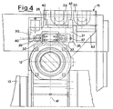
- Figure 4 displays how each "L"-shaped wedge element 32 and 33 is further fastened by means of a small plate 39 provided above the base of the "L"-shape of the wedge element.
- the small plate 39 constrains, through screws 40, the wedge element 32 to the enlarged end portion 30 of the "C"-contoured portion 26. In an analogous way, the small plate 39 constrains, through screws 40, the wedge element 33 to the support block 35.
- Figures 4 and 5 show top plan views of the support foot 15 of the tie-rod rolling stand according to the invention, which has a nonsymmetrical body aligned with the axis 41 running through the centre of the tie-rods 14. From its sleeve portion 25, the body of the support foot 15 extends towards the outside of the rolling stand into a slant portion 42 which acts like a strut in order to counteract the axial thrusts generated by the rolling rolls 13.
- strut-acting portion 42 the hollows 20 are provided which receive the eye tie-rods 26 -- with, in the instant example, two of them being provided.
- the general structure of the support feet 15 is such as to bear the operating axial load which is generated during the rolling of a nonsymmetrical rolled section.
- the rolling stand according to the present invention displays a very high stiffness and secures that rolled sections will be produced in the desired size, with very narrow dimensional tolerances.
- the shape of the upwards/downwards extending "C"-shaped portions 26, as well as of the wedge elements 32 and 33 results to be designed for an easy servicing.
- the wedge elements 32 and 33 can thus be replaced and in the event that their coupling planes with the contoured portions 26 are no longer perfectly smooth, they can be levelled off, with a correct coupling being restored.
- the support block 35 of the wedge element 33 can be reprocessed in order to restore the coupling planarity of the parts.
- the rolling stand of the present invention can be provided with such support feet at one shoulder only, or, according to and alternative embodiment, said support feet can be provided at both rolling stand shoulders.
- vertical ribs 43 can be provided which act to further stiffen the structure thereof, i.e., stabilize the whole tie-rod rolling stand.
- a tie-rod rolling stand according to the present invention is suitable for being horizontally opened, i.e., by moving apart the shoulders containing the carriers and the supports, in order to remove the rolling rolls, which remain in their position, and replace them with a new pair of rolling rolls.
- This result can be attained because both the old (i.e., presently installed) rolling rolls, and the new rolling rolls (i.e., the rolling rolls which the operator wishes to install) are borne by a suitable service unit according to U.S. patent No. 4,552,007.
Landscapes
- Engineering & Computer Science (AREA)
- Mechanical Engineering (AREA)
- Reduction Rolling/Reduction Stand/Operation Of Reduction Machine (AREA)
- Heat Treatment Of Articles (AREA)
- Rehabilitation Tools (AREA)
- Orthopedics, Nursing, And Contraception (AREA)
Abstract
Description
- The present invention relates to a rolling stand of the type with tie-rods, endowed with extremely high strength to axial stresses, which makes it possible high-precision nonsymmetrical-profile rolled sections to be obtained
- The presently used rolling stands of the type with tie-rods (referred to in the following as "tie-rod rolling stands") are such as to enable also rolled sections with particular contours, such as a double-"T" contours, to be manufactured with very good quality.
- However, it should be remarked here that these rolling stands operate very well for rolled sections with symmetrical contour. An example of a tie-rod rolling stand of the above type is disclosed in detail in European patent No. 0 166 478.
- If the contour of the cross-section of the rolled section is nonsymmetrical, for example an "L"-shaped contour, stresses arise which, by being oriented parallel to the axis of the rolling rolls, cannot be easily counteracted.
- The axial stresses have a detrimental impact on the whole structure of the rolling stand, causing mutually engaged moving components to undergo wear during the rolling process. Among such mutually moving components, we remind here, for example, the lead nuts or threaded rings installed in the carriers, and those components which perform the task of guiding the movement.
- This drawback generates clearances in the rolling stand and can also endanger the dimensional tolerances of the rolled section product which consequently may not meet the requirements.
- The purpose of the present invention is of obviating these drawbacks, by providing a tie-rod rolling stand capable of meeting the necessary requirements of strength and stability, i.e., of allowing rolled sections of non-symmetrical profile with any sizes and with very precise dimensional tolerances to be obtained, while simultaneously preventing the components which constitute the rolling stand from undergoing wear.
- This purpose is achieved by a rolling stand of the type with tie-rods which displays the features expounded in the appended claims.
- The structural and functional characteristics of the invention, and its advantages over the prior art, will be still more evident from an examination of the following disclosure made by referring to the accompanying schematic drawings, which display an example of a tie-rod rolling stand embodying the principles of the same invention.
- In the drawings:
- -- Figure 1 shows a front elevation view illustrating a rolling stand of the type with tie-rods according to the present invention;
- -- Figure 2 shows a vertical sectional view, on an enlarged scale, of a side portion of the rolling stand, illustrating a stabilizer/contrast foot provided sideways of the carriers which support the neck of the rolling rolls;
- -- Figure 3 shows a top perspective view illustrating a portion of a shoulder of the rolling stand as displayed in Figure 2, according to the present invention;
- -- Figure 4 shows a top plan view illustrating a half of a shoulder of the rolling stand as displayed in Figure 2, without the eye tie-rods which are used to fasten it to the stand base;
- -- Figure 5 shows a horizontal sectional view seen from upwards, of the shoulder with the stabilizer/contrast foot at the bearings which support the neck of a rolling roll between the tie-rods or setscrews;
- -- Figure 6 shows a vertical sectional view of a half of the shoulder with foot of Figure 2.
-
- Referring to the figures, the tie-rod rolling stand according to the invention is generally indicated with 10 and is structurally formed by a
stand base 11 performing the task of containingcarriers 12 bearing at least one pair of respectivehorizontal rolling rolls 13. - The rolling rod according to the present invention is provided with tie-rods or
setscrews 14 which enable therolling rolls 13 to be adjusted in position relatively to each other, driven by an adjustment/synchronism unit arranged above the rolling stand and not illustrated, because it is of a well-known type for those skilled in the art. This unit causes thecarriers 12 bearing therolling rolls 13, to be vertically moved towards/apart from each other. - On the
stand base 11, according to the present invention, four support feet or bases, generally indicated with 15, are mounted and constrained to it by means of eye tie-rods 16 which are hinged, at theirbottom ends 17, onto thestand base 11. - The eye tie-
rods 16 are hinged, through ashaft 18, insidehollows 19 provided in thestand base 11, can rotate around theshaft 18 and can be inserted inside purposely providedhollows 20 of thesupport feet 15, inside which they are fastened by means ofnuts 21. - The
support feet 15 are also centered relatively to thestand base 11, by means ofkeys 22 positioned inside complementary, mutually oppositekey seats support feet 15 and in thestand base 11, and protruding ribs suitable for being housed inside corresponding seats, not shown in the drawings. - Each
support foot 15 protrudes inside the interior of the rolling stand, to form asleeve portion 25 which receives a central, smooth portion 25' of the tie-rods 14. - Outside the rolling stand, each support
foot 15, according to the present invention, extends into two "C"-shaped portions 26, extending upwards and downwards to surround, at least partially, the external sides of thecarriers 12. - The tie-
rods 14 have screw-threadedportions 27, provided on opposite sides of thesupport foot 15, which receivering nuts 28 integral with the stand base relatively to the rotation inside thecarriers 12. - The
carriers 12 are provided, along side portions thereof, in perpendicular direction to the direction of the axes of therolling rolls 13, with outwards protruding,vertical ribs 29 which get engaged inside thecontoured portions 26 of thesupport feet 15. - As shown by Figures 2-5, the "C"-
shaped portions 26 have, in section, an enlargedend portion 30 and an opposite,thinned end portion 31. Insidesuch end portions adjustment wedge elements wedge elements - As it can clearly be seen from Figure 4, the enlarged
end portion 30 is facing the interior of the rolling stand in which the rolling rolls are housed, and, in this example, therelevant wedge element 32 is fastened by means of at least twofastening screws 34. - The opposite,
thinner end portion 31 facing the outside of the rolling stand houses an "L"-shaped support block 35 fastened by means of threeside screws 36. In its turn, thewedge element 33 is fastened by means ofscrews 37 to thesupport block 35 and is constrained to the whole structure of thesupport foot 15. - The
wedge elements end portion 30 and on thesupport block 35. - However, on both said
wedge elements runners 38 slide, which act as freely removable sliding elements, constrained, on opposite sides, to the bottom end of thevertical rib 29 protruding from thecarriers 12. - Said crowned
runners 38 enable thecarriers 12 to match the deformations of therolling rolls 13. - Figure 4 displays how each "L"-
shaped wedge element small plate 39 provided above the base of the "L"-shape of the wedge element. - The
small plate 39 constrains, throughscrews 40, thewedge element 32 to the enlargedend portion 30 of the "C"-contouredportion 26. In an analogous way, thesmall plate 39 constrains, throughscrews 40, thewedge element 33 to thesupport block 35. - Figures 4 and 5 show top plan views of the
support foot 15 of the tie-rod rolling stand according to the invention, which has a nonsymmetrical body aligned with theaxis 41 running through the centre of the tie-rods 14. From itssleeve portion 25, the body of thesupport foot 15 extends towards the outside of the rolling stand into aslant portion 42 which acts like a strut in order to counteract the axial thrusts generated by therolling rolls 13. - In the slant, strut-acting
portion 42 thehollows 20 are provided which receive the eye tie-rods 26 -- with, in the instant example, two of them being provided. - The general structure of the
support feet 15 is such as to bear the operating axial load which is generated during the rolling of a nonsymmetrical rolled section. - In this situation of the structure, the rolling stand according to the present invention displays a very high stiffness and secures that rolled sections will be produced in the desired size, with very narrow dimensional tolerances. Of course, the shape of the upwards/downwards extending "C"-
shaped portions 26, as well as of thewedge elements - In the event that the mutually engaging parts undergo wear owing to the stresses they are submitted to, and to their mutual sliding, the
screws wedge elements screws 36 to be easily and rapidly removed, with thesupport block 35 being as easily and rapidly removed too. - The
wedge elements contoured portions 26 are no longer perfectly smooth, they can be levelled off, with a correct coupling being restored. - Also the
support block 35 of thewedge element 33, subject to a higher axial stress, can be reprocessed in order to restore the coupling planarity of the parts. - The rolling stand of the present invention can be provided with such support feet at one shoulder only, or, according to and alternative embodiment, said support feet can be provided at both rolling stand shoulders.
- Externally to the support feet on the "C"-shaped portions,
vertical ribs 43 can be provided which act to further stiffen the structure thereof, i.e., stabilize the whole tie-rod rolling stand. - Also a tie-rod rolling stand according to the present invention is suitable for being horizontally opened, i.e., by moving apart the shoulders containing the carriers and the supports, in order to remove the rolling rolls, which remain in their position, and replace them with a new pair of rolling rolls. This result can be attained because both the old (i.e., presently installed) rolling rolls, and the new rolling rolls (i.e., the rolling rolls which the operator wishes to install) are borne by a suitable service unit according to U.S. patent No. 4,552,007.
Claims (10)
- Rolling stand of the type with tie-rods, endowed with extremely high strength to axial stresses, which comprises a stand base (11) supporting at least two rolling rolls (13) borne by carriers (12) which can be vertically moved in order to be approached/moved apart from each other, by means of four vertical tie-rods (14) displaying screw-threaded portions (27) provided on opposite sides of at least one pair of support feet (15) arranged between the stand base and the carriers (12) which support and contain a central smooth portion (25') of the tie-rods (15), characterized in that from at least one of the support feet (15), a contoured portion (26) extends upwards and downwards in parallel direction to the tie-rods (14), which contoured portion (26) is suitable for housing and guiding a vertical rib (29) protruding outwards from said carriers (12), with both said contoured portion (26) and said vertical rib (29) bearing, on mutually opposite surfaces, freely removable adjustment/sliding elements (32, 33, 38).
- Rolling stand according to claim 1, characterized in that said contoured portions (26) and said vertical ribs (29) are arranged at opposite side ends of said carriers (12) aligned to an axis (41) running through one pair of tie-rods (14) of a same rolling stand shoulder.
- Rolling stand according to claim 1, characterized in that said contoured portions (26) have a "C"-shaped cross-section.
- Rolling stand according to claim 3, characterized in that said contoured portions with "C"-shaped cross-section have an enlaged end portion (30) and an opposite, thinned end portion (31) which bear, constrained, both said adjustment/sliding elements (32, 33), with said vertical ribs (29) constraining complementary, crowned sliding elements (38).
- Rolling stand according to claim 1, characterized in that said adjustment/sliding elements constrained to said contoured portion (26) are wedge elements (32, 33).
- Rolling stand according to claim 5, characterized in that at least one of said wedge elements (33) is fastened onto a small support block (35) which, in its turn, is fastened to said contoured portion (26) in a thinned portion (31) thereof.
- Rolling stand according to claim 6, characterized in that said wedge elements (32, 33) have an "L"-shape and are constrained, at a base portion of said "L"-shape thereof, the one (32) to said contoured portion (26), and the other one (33) to said support block (35).
- Rolling stand according to claim 1, characterized in that said support feet (15) are constrained to said stand base (11) by means of eye tie-rods (16), with said stand base (11) and said support feet (15) being kept centered by keys (22) housed inside mutually complementary seats (23, 24) which are provided partially on said support feet (15) and partially on said stand base (11).
- Rolling stand according to claim 1, characterized in that said support foot (15), in a central portion thereof, extends towards the outside into a slant, strut-acting portion (42).
- Rolling stand according to claim 1, characterized in that said contoured portions (26) of said support feet (15) are externally provided with vertical stiffening ribs (43).
Priority Applications (4)
| Application Number | Priority Date | Filing Date | Title |
|---|---|---|---|
| DE69416408T DE69416408T2 (en) | 1994-09-29 | 1994-09-29 | Roll stand with tie rods of extremely high tensile strength |
| ES94202813T ES2127884T3 (en) | 1994-09-29 | 1994-09-29 | ROLLER WITH BRACES AND WITH EXTRAORDINARY RESISTANCE TO AXIAL EFFORTS. |
| EP94202813A EP0704256B1 (en) | 1994-09-29 | 1994-09-29 | Rolling stand with tie-rods with extremely high strength to axial stresses |
| AT94202813T ATE176412T1 (en) | 1994-09-29 | 1994-09-29 | ROLLING STAND WITH TIE ANCHORS OF EXTREMELY HIGH TENSILE STRENGTH |
Applications Claiming Priority (1)
| Application Number | Priority Date | Filing Date | Title |
|---|---|---|---|
| EP94202813A EP0704256B1 (en) | 1994-09-29 | 1994-09-29 | Rolling stand with tie-rods with extremely high strength to axial stresses |
Publications (2)
| Publication Number | Publication Date |
|---|---|
| EP0704256A1 EP0704256A1 (en) | 1996-04-03 |
| EP0704256B1 true EP0704256B1 (en) | 1999-02-03 |
Family
ID=8217239
Family Applications (1)
| Application Number | Title | Priority Date | Filing Date |
|---|---|---|---|
| EP94202813A Expired - Lifetime EP0704256B1 (en) | 1994-09-29 | 1994-09-29 | Rolling stand with tie-rods with extremely high strength to axial stresses |
Country Status (4)
| Country | Link |
|---|---|
| EP (1) | EP0704256B1 (en) |
| AT (1) | ATE176412T1 (en) |
| DE (1) | DE69416408T2 (en) |
| ES (1) | ES2127884T3 (en) |
Families Citing this family (3)
| Publication number | Priority date | Publication date | Assignee | Title |
|---|---|---|---|---|
| RU2210448C1 (en) * | 2001-11-13 | 2003-08-20 | Общество с ограниченной ответственностью "Инвестметаллургмаш" | Housing-free prestressed rolling stand |
| CN105414195B (en) * | 2015-12-18 | 2017-12-19 | 重庆麦拓科技有限公司 | A kind of short stress path rolling mill |
| CN113182357A (en) * | 2021-04-06 | 2021-07-30 | 马鞍山市银鼎机械制造有限公司 | Short stress path rolling mill capable of preventing roller from burning |
Family Cites Families (3)
| Publication number | Priority date | Publication date | Assignee | Title |
|---|---|---|---|---|
| GB1183573A (en) * | 1966-06-03 | 1970-03-11 | Davy & United Eng Co Ltd | Rolling Mills |
| JPS5316791B2 (en) * | 1974-02-18 | 1978-06-03 | ||
| IT1174098B (en) * | 1984-05-28 | 1987-07-01 | Pomini Farrel Spa | LAMINATION CAGE OF THE TYPE OF TIE RODS WITH OSCILATING SUPPORTS WITH INTERMEDIATE SUPPORT BASES |
-
1994
- 1994-09-29 ES ES94202813T patent/ES2127884T3/en not_active Expired - Lifetime
- 1994-09-29 AT AT94202813T patent/ATE176412T1/en active
- 1994-09-29 DE DE69416408T patent/DE69416408T2/en not_active Expired - Lifetime
- 1994-09-29 EP EP94202813A patent/EP0704256B1/en not_active Expired - Lifetime
Also Published As
| Publication number | Publication date |
|---|---|
| DE69416408D1 (en) | 1999-03-18 |
| DE69416408T2 (en) | 1999-07-29 |
| ES2127884T3 (en) | 1999-05-01 |
| ATE176412T1 (en) | 1999-02-15 |
| EP0704256A1 (en) | 1996-04-03 |
Similar Documents
| Publication | Publication Date | Title |
|---|---|---|
| US4715206A (en) | Rolling stand of the type with tie-rods with oscillating supports with interchangeable intermediate holder bases | |
| JP2607859B2 (en) | Mold clamping device for equipping heavy large molds for plastic injection molding machines | |
| US4905493A (en) | Rolling stand which can be converted into a four-high stand or universal stand, and rolling line which employs such convertible stand | |
| CN87100390A (en) | Mill stand | |
| RU2050994C1 (en) | Method of rolling mill operation at making rolled strip | |
| EP0704256A1 (en) | Rolling stand with tie-rods with extremely high strength to axial stresses | |
| US5551273A (en) | Rolling stand with tie-rods with extremely high strength to axial stresses | |
| US3055242A (en) | Rolling mills | |
| RU94035662A (en) | Rolling mill with axial displacement of rolls | |
| CA2463075C (en) | Rolling device | |
| US5090228A (en) | Window and roll chock arrangement for a rolling mill | |
| JPH04224018A (en) | Correcting device | |
| US5195347A (en) | Guide device for shape rolling | |
| US5457979A (en) | Universal demountable rolling mill stand | |
| US4026136A (en) | Method and apparatus for changing rolls for a rolling mill | |
| US5752404A (en) | Roll shifting system for rolling mills | |
| TW424008B (en) | A metal band product rolling installation and method for implementing the same | |
| CN1060976C (en) | Rolling stand with tie-rods with extremely high strength to axial stresses | |
| CN221361889U (en) | Rolling mill backing roll is used in stainless steel strip production | |
| CN101346195A (en) | Device for rotationally locking the back-up roll balance mechanism of a rolling mill stand | |
| US5787749A (en) | Rolling mill stand | |
| GB1569029A (en) | Pipewelding machine with replaceable rolls | |
| CN214556270U (en) | Fixing device of aluminum cold rolling working roll | |
| SU1680405A1 (en) | Shaping mill | |
| US4753097A (en) | Universal roll stand |
Legal Events
| Date | Code | Title | Description |
|---|---|---|---|
| PUAI | Public reference made under article 153(3) epc to a published international application that has entered the european phase |
Free format text: ORIGINAL CODE: 0009012 |
|
| AK | Designated contracting states |
Kind code of ref document: A1 Designated state(s): AT BE DE ES FR GB SE |
|
| 17P | Request for examination filed |
Effective date: 19961001 |
|
| GRAG | Despatch of communication of intention to grant |
Free format text: ORIGINAL CODE: EPIDOS AGRA |
|
| 17Q | First examination report despatched |
Effective date: 19980310 |
|
| GRAG | Despatch of communication of intention to grant |
Free format text: ORIGINAL CODE: EPIDOS AGRA |
|
| GRAH | Despatch of communication of intention to grant a patent |
Free format text: ORIGINAL CODE: EPIDOS IGRA |
|
| GRAH | Despatch of communication of intention to grant a patent |
Free format text: ORIGINAL CODE: EPIDOS IGRA |
|
| GRAA | (expected) grant |
Free format text: ORIGINAL CODE: 0009210 |
|
| RAP1 | Party data changed (applicant data changed or rights of an application transferred) |
Owner name: TECHINT COMPAGNIA TECNICA INTERNAZIONALE S.P.A. |
|
| AK | Designated contracting states |
Kind code of ref document: B1 Designated state(s): AT BE DE ES FR GB SE |
|
| REF | Corresponds to: |
Ref document number: 176412 Country of ref document: AT Date of ref document: 19990215 Kind code of ref document: T |
|
| REF | Corresponds to: |
Ref document number: 69416408 Country of ref document: DE Date of ref document: 19990318 |
|
| ET | Fr: translation filed | ||
| REG | Reference to a national code |
Ref country code: ES Ref legal event code: FG2A Ref document number: 2127884 Country of ref document: ES Kind code of ref document: T3 |
|
| PLBE | No opposition filed within time limit |
Free format text: ORIGINAL CODE: 0009261 |
|
| STAA | Information on the status of an ep patent application or granted ep patent |
Free format text: STATUS: NO OPPOSITION FILED WITHIN TIME LIMIT |
|
| 26N | No opposition filed | ||
| REG | Reference to a national code |
Ref country code: GB Ref legal event code: IF02 |
|
| PGFP | Annual fee paid to national office [announced via postgrant information from national office to epo] |
Ref country code: FR Payment date: 20030909 Year of fee payment: 10 |
|
| PGFP | Annual fee paid to national office [announced via postgrant information from national office to epo] |
Ref country code: BE Payment date: 20031208 Year of fee payment: 10 |
|
| PG25 | Lapsed in a contracting state [announced via postgrant information from national office to epo] |
Ref country code: BE Free format text: LAPSE BECAUSE OF NON-PAYMENT OF DUE FEES Effective date: 20040930 |
|
| BERE | Be: lapsed |
Owner name: *TECHINT COMPAGNIA TECNICA INTERNAZIONALE S.P.A. Effective date: 20040930 |
|
| PG25 | Lapsed in a contracting state [announced via postgrant information from national office to epo] |
Ref country code: FR Free format text: LAPSE BECAUSE OF NON-PAYMENT OF DUE FEES Effective date: 20050531 |
|
| REG | Reference to a national code |
Ref country code: FR Ref legal event code: ST |
|
| BERE | Be: lapsed |
Owner name: *TECHINT COMPAGNIA TECNICA INTERNAZIONALE S.P.A. Effective date: 20040930 |
|
| PGFP | Annual fee paid to national office [announced via postgrant information from national office to epo] |
Ref country code: SE Payment date: 20120911 Year of fee payment: 19 |
|
| PGFP | Annual fee paid to national office [announced via postgrant information from national office to epo] |
Ref country code: AT Payment date: 20120810 Year of fee payment: 19 |
|
| PGFP | Annual fee paid to national office [announced via postgrant information from national office to epo] |
Ref country code: GB Payment date: 20130911 Year of fee payment: 20 |
|
| PGFP | Annual fee paid to national office [announced via postgrant information from national office to epo] |
Ref country code: DE Payment date: 20131120 Year of fee payment: 20 |
|
| PGFP | Annual fee paid to national office [announced via postgrant information from national office to epo] |
Ref country code: ES Payment date: 20131030 Year of fee payment: 20 |
|
| REG | Reference to a national code |
Ref country code: SE Ref legal event code: EUG |
|
| PG25 | Lapsed in a contracting state [announced via postgrant information from national office to epo] |
Ref country code: SE Free format text: LAPSE BECAUSE OF NON-PAYMENT OF DUE FEES Effective date: 20130930 |
|
| REG | Reference to a national code |
Ref country code: AT Ref legal event code: MM01 Ref document number: 176412 Country of ref document: AT Kind code of ref document: T Effective date: 20130929 |
|
| PG25 | Lapsed in a contracting state [announced via postgrant information from national office to epo] |
Ref country code: AT Free format text: LAPSE BECAUSE OF NON-PAYMENT OF DUE FEES Effective date: 20130929 |
|
| REG | Reference to a national code |
Ref country code: DE Ref legal event code: R071 Ref document number: 69416408 Country of ref document: DE |
|
| REG | Reference to a national code |
Ref country code: DE Ref legal event code: R071 Ref document number: 69416408 Country of ref document: DE |
|
| REG | Reference to a national code |
Ref country code: GB Ref legal event code: PE20 Expiry date: 20140928 |
|
| PG25 | Lapsed in a contracting state [announced via postgrant information from national office to epo] |
Ref country code: DE Free format text: LAPSE BECAUSE OF EXPIRATION OF PROTECTION Effective date: 20140930 |
|
| PG25 | Lapsed in a contracting state [announced via postgrant information from national office to epo] |
Ref country code: GB Free format text: LAPSE BECAUSE OF EXPIRATION OF PROTECTION Effective date: 20140928 |
|
| REG | Reference to a national code |
Ref country code: ES Ref legal event code: FD2A Effective date: 20150108 |
|
| PG25 | Lapsed in a contracting state [announced via postgrant information from national office to epo] |
Ref country code: ES Free format text: LAPSE BECAUSE OF EXPIRATION OF PROTECTION Effective date: 20140930 |