EP0704049B1 - Float-controlled level switch with adjustable switching points - Google Patents
Float-controlled level switch with adjustable switching points Download PDFInfo
- Publication number
- EP0704049B1 EP0704049B1 EP95913893A EP95913893A EP0704049B1 EP 0704049 B1 EP0704049 B1 EP 0704049B1 EP 95913893 A EP95913893 A EP 95913893A EP 95913893 A EP95913893 A EP 95913893A EP 0704049 B1 EP0704049 B1 EP 0704049B1
- Authority
- EP
- European Patent Office
- Prior art keywords
- float
- switching
- level switch
- elements
- controlled level
- Prior art date
- Legal status (The legal status is an assumption and is not a legal conclusion. Google has not performed a legal analysis and makes no representation as to the accuracy of the status listed.)
- Expired - Lifetime
Links
Images
Classifications
-
- H—ELECTRICITY
- H01—ELECTRIC ELEMENTS
- H01H—ELECTRIC SWITCHES; RELAYS; SELECTORS; EMERGENCY PROTECTIVE DEVICES
- H01H1/00—Contacts
- H01H1/58—Electric connections to or between contacts; Terminals
- H01H1/5833—Electric connections to or between contacts; Terminals comprising an articulating, sliding or rolling contact between movable contact and terminal
-
- G—PHYSICS
- G01—MEASURING; TESTING
- G01F—MEASURING VOLUME, VOLUME FLOW, MASS FLOW OR LIQUID LEVEL; METERING BY VOLUME
- G01F23/00—Indicating or measuring liquid level or level of fluent solid material, e.g. indicating in terms of volume or indicating by means of an alarm
- G01F23/30—Indicating or measuring liquid level or level of fluent solid material, e.g. indicating in terms of volume or indicating by means of an alarm by floats
- G01F23/64—Indicating or measuring liquid level or level of fluent solid material, e.g. indicating in terms of volume or indicating by means of an alarm by floats of the free float type without mechanical transmission elements
- G01F23/72—Indicating or measuring liquid level or level of fluent solid material, e.g. indicating in terms of volume or indicating by means of an alarm by floats of the free float type without mechanical transmission elements using magnetically actuated indicating means
- G01F23/74—Indicating or measuring liquid level or level of fluent solid material, e.g. indicating in terms of volume or indicating by means of an alarm by floats of the free float type without mechanical transmission elements using magnetically actuated indicating means for sensing changes in level only at discrete points
-
- H—ELECTRICITY
- H01—ELECTRIC ELEMENTS
- H01H—ELECTRIC SWITCHES; RELAYS; SELECTORS; EMERGENCY PROTECTIVE DEVICES
- H01H36/00—Switches actuated by change of magnetic field or of electric field, e.g. by change of relative position of magnet and switch, by shielding
- H01H36/02—Switches actuated by change of magnetic field or of electric field, e.g. by change of relative position of magnet and switch, by shielding actuated by movement of a float carrying a magnet
Definitions
- the invention relates to a float-controlled level switch with electrical and / or electronic switching elements, of which in the case of DE 25 36 843 B2 only a single one (reed switch) is present, which, actuated by the magnetic field of a float magnet, changes its states without contact generate binary or analog signals, several switching points lying one above the other being infinitely adjustable to the level of the liquid to be regulated, which drives a float that is guided on a pipe.
- the various switching points make it possible to continuously regulate the level of liquids in selected height ranges, especially in connection with changing operating conditions.
- a known from DE-OS 1 690 197 "magnetic float switch" of the aforementioned type avoids the disadvantage of other similar switches that no stepless adjustment is possible due to construction-related distances between pluggable switch elements, in that several around a central guide tube (3) parallel bolts (9) are arranged equidistantly, each of which carries a magnetic switch (7) in the vicinity of the tube (3) receiving a switching magnet (4), which is connected to a float (6) by means of a rod (5) arranged therein Each switch (7) is guided on its bolt (9) and can be locked by means of a screw. The whole thing is covered by a protective hood (15).
- the parts carrying the electrical current are: the connecting cable 13, the lines 14, the busbars 15 used in the profile rod 11, the carriers attached to the switching elements 12, contact springs 16 and reed switches 17th
- auxiliary magnets 18 are arranged next to reed switches 17. All parts of the level switch that come into contact with the medium are made of corrosion-resistant material.
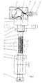
- FIG. 1 shows the installation of the level switch by means of flange 5.
- any other suitable closure part of the container can also be used for this after appropriate processing.
- the prepared wires of the connecting cable 13 can be connected to the connecting terminals 2.
- the adjustment spindles 19 are accessible, which can be rotated using a suitable tool.
- the associated switching element carriers 12 and thus the switching points of the level switch move up and down.
- the adjusting spindles 19 are fixed in their position by screwing on a pressure plate and thus also the switching element carrier 12.
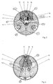
- the switching element carrier 12 move in the guideways 21 of the profile rod 11.
- these guideways 21 are arranged one behind the other and offset by 120 angular degrees on the circumference of the profiled rod 11. The distances between them can be any.
- the profile rod 11 consists of electrically non-conductive material, in which two conductor rails 15 are embedded at the level of the guide tracks 21.
- the busbars 15 are connected directly to the terminals 2 via the lines 14 in channels 23. When the height of these contact halves is adjusted, the contact springs 16 of the switching element carriers slide on the contact surfaces 15, 1 of the busbars 15. Appropriate material selection and surface treatment of both contact elements ensure reliable contact with a low contact resistance.
- the contact springs 16 are electrically connected directly to the reed switches 17.
- the reed switches 17 and the auxiliary magnets 18 are housed in pairs in the cavities of the switching element carrier 12 and, after their adjustment, are cast with electrically non-conductive material.
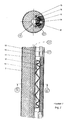
- FIG. 4 shows the arrangement of the profile rod 11 and the switching element carrier 12 without the possibility of adjustment by the adjusting spindles 19.
- the profile rod 11 is removed from the level switch after opening the terminal housing 1.
- the profile rod 11 After adjusting the switching element carrier 12, the profile rod 11 is reinserted in the level switch and fixed in its position.
- the profile rod 11 has only a single, continuous guideway 22, in which the busbars 15 and the switching element carrier 12 are arranged one behind the other, at the intervals of the switching points.
Abstract
Description
Die Erfindung betrifft einen schwimmergesteuerten Niveau-Schalter
mit elektrischen und/oder elektronischen Schaltelementen,
von denen im Falle der DE 25 36 843 B2 nur ein
einziges (Reed-Schalter) vorhanden ist, welche berührungslos
durch das magnetische Feld eines Schwimmermagneten betätigt
ihre Zustände ändern und dabei binäre oder analoge
Signale erzeugen, wobei mehrere übereinanderliegende Schaltpunkte
stufenlos auf die zu regelnden Niveauhöhen der Flüssigkeit
einstellbar sind, die einen Schwimmer auftreibt, der
an einem Rohr geführt ist. - Die verschiedenen Schaltpunkte
ermöglichen es, Pegelstände von Flüssigkeiten in ausgewählten
Höhenbereichen, vor allem auch im Zusammenhang mit sich ändernden
Betriebsbedingungen, stufenlos zu regeln.
Ein aus der DE-OS 1 690 197 bekannter "Magnet-Schwimmerschalter"
der zuvor genannten Art vermeidet den Nachteil
anderer ähnlicher Schalter, daß aufgrund baubedingter Abstände
zwischen steckbaren Schalterelementen keine stufenlose
Verstellung möglich ist, dadurch, daß um ein zentrales
Führungsrohr (3) mehrere parallele Bolzen (9) äquidistant
angeordnet sind, von denen jeder einen Magnetschalter (7) in
der Nähe des einen Schaltmagneten (4) aufnehmenden Rohrs (3)
trägt, welcher mittels einer darin angeordneten Stange (5)
mit einem Schwimmer (6) verbunden ist, wobei jeder Schalter
(7) an seinem Bolzen (9) geführt und mittels einer Schraube
feststellbar ist. Das Ganze deckt eine Schutzhaube (15).
Nachteilig ist an diesem bekannten schwimmergesteuerten
Niveau-Schalter mit stufenlos einstellbaren Schaltpunkten,
daß er einen relativ großen Durchmesser (den der Haube 15)
besitzt; dazu auch noch eine um die axiale Ausdehnung der
Stange (5) vergrößerte Gesamtlänge, die mit der Stangenlänge
zunimmt, wobei der Schwimmer (6) mehr belastet wird und
schließlich schwebt oder sinkt, falls er nicht vergrößert
wird. Außerdem kann sich der Stab (5) und Schwimmer (6) wie
ein Pendel aufhängende Schaltmagnet (4) im Führungsrohr (3)
verkanten.
Diesen Nachteil vermeidet der erfindungsgemäße Niveau-Schalter
gemäß Anspruch 1 mittels dessen kennzeichnenden Merkmalen
die ihm zu einer viel schlankeren Bauform bei verminderter
Gesamtlänge verhelfen.
Aus der DE-GM 7 102 291 (Fig. 1) ist es bei einer "Vorrichtung
zur Bestimmung des Spiegels einer Flüssigkeit in einem
geschlossenen Gefäß" lediglich bekannt, ein einziges Schaltelement
(Reed-Kontakt 13) in einer rohrförmigen Hülle (1)
mit schließendem Boden 815) auf diesem abzustützen und diese
Hülle axial (vertikal) verschiebbar in einem rohrförmigen
Mantel (11) anzuordnen, auf dem ein Schwimmer (20, mit Magnetring
21) hoch und nieder gleitet. Dabei ist das Schaltelement
(13) "ortsfest, das heißt, nur zu Justierzwecken
veränderbar, angeordnet", indem die Hülle (1) mittels einer
Schraubmutter (4) im Mantel (11) auf- und abwärts zu verschieben
ist.The invention relates to a float-controlled level switch with electrical and / or electronic switching elements, of which in the case of DE 25 36 843 B2 only a single one (reed switch) is present, which, actuated by the magnetic field of a float magnet, changes its states without contact generate binary or analog signals, several switching points lying one above the other being infinitely adjustable to the level of the liquid to be regulated, which drives a float that is guided on a pipe. - The various switching points make it possible to continuously regulate the level of liquids in selected height ranges, especially in connection with changing operating conditions.
A known from DE-OS 1 690 197 "magnetic float switch" of the aforementioned type avoids the disadvantage of other similar switches that no stepless adjustment is possible due to construction-related distances between pluggable switch elements, in that several around a central guide tube (3) parallel bolts (9) are arranged equidistantly, each of which carries a magnetic switch (7) in the vicinity of the tube (3) receiving a switching magnet (4), which is connected to a float (6) by means of a rod (5) arranged therein Each switch (7) is guided on its bolt (9) and can be locked by means of a screw. The whole thing is covered by a protective hood (15). The disadvantage of this known float-controlled level switch with infinitely adjustable switching points that it has a relatively large diameter (that of the hood 15); in addition, an overall length increased by the axial extension of the rod (5), which increases with the rod length, the float (6) being subjected to greater loads and finally floating or sinking if it is not enlarged. In addition, the rod (5) and float (6) can tilt like a pendulum-mounted switching magnet (4) in the guide tube (3).
This disadvantage is avoided by the level switch according to the invention according to claim 1 by means of its characteristic features which help it to achieve a much slimmer design with a reduced overall length.
From DE-GM 7 102 291 (Fig. 1) it is only known in a "device for determining the level of a liquid in a closed vessel" to have a single switching element (reed contact 13) in a tubular casing (1) closing bottom 815) on this and to arrange this sheath axially (vertically) displaceably in a tubular jacket (11) on which a float (20, with magnetic ring 21) slides up and down. The switching element (13) is "stationary, that is to say can only be changed for adjustment purposes", in that the casing (1) can be moved up and down in the casing (11) by means of a screw nut (4).
Vorteilhafte Ausgestaltungen und Weiterbildungen des erfindungsgemäßen
Niveau-Schalters gemäß Hauptanspruch (Nr. 1)
sind in den Unteranspriichen gekennzeichnet.
Die Ausbildung der Verstellelemente gemäß Anspruch 2 als
Gewindespindeln ergibt im Vergleich mit den Klemmschrauben
des Schalters gemäß DE-OS 1 690 197 eine wesentlich höhere
Verstellgenauigkeit. Advantageous refinements and developments of the level switch according to the invention according to the main claim (No. 1) are characterized in the dependent claims.
The design of the adjusting elements according to
Im folgenden ist die Erfindung anhand zweier durch die Zeichnung
beispielhaft dargestellter und bevorzugter Ausführungsformen des
erfindungsgemäßen schwimmergesteuerten Niveau-Schalters im
einzelnen erläutert.
Sie zeigt:
- Figur 1:
- Eine Gesamtansicht der ersten Ausführungsform
"Verstellung der
Schaltelemente 12 mittelsVerstellspindeln 19", teilweise aufgebrochen, unterbrochen und axial geschnitten. - Figur 2:
- Eine vergrößerte Einzelheit Z von Fig. 1 im Quer-bzw. Längsschnitt
- Figur 3:
- Eine vergrößerte Stirnansicht des in der
Figur 2 Dargestellten (im Schnitt gezeichnet). - Figur 4:
- Eine vergrößerte Stirnansicht der zweiten Ausführungsform
"Verstellung der
Schaltelementeträger 12 ohneVerstellspindel 19" (im Schnitt gezeichnet).
She shows:
- Figure 1 :
- An overall view of the first embodiment "adjustment of the
switching elements 12 by means of adjustingspindles 19", partially broken open, interrupted and cut axially. - Figure 2 :
- An enlarged detail Z of Fig. 1 in the transverse or. Longitudinal section
- Figure 3 :
- An enlarged end view of that shown in Figure 2 (shown in section).
- Figure 4 :
- An enlarged front view of the second embodiment "adjustment of the
switching element carrier 12 without adjustingspindle 19" (shown in section).
In beiden Ausführungsbeispielen besteht der erfindungsgemäße Niveau-Schalter, der vertikal im Flüssigkeitsbehälter eingebaut wird, von oben nach unten gesehen, hauptsächlich aus:
- dem Klemmengehäuse 1 mit seinen
Anschlußklemmen 2 und derKabelverschraubung 3, - dem
Anschlußkopf 4 zur Befestigung des Schalters am Behälter im Beispiel mittels Flansch 5 undGegenmutter 6, - dem mit dem
Anschlußkopf 4 druckdicht verbundenen und nach unten hingeschlossenen Gleitrohr 7, - dem
Schwimmer 8 mit dem in seinem Inneren sich befindenden Permanent-Magneten 9 und demStellring 10 auf demGleitrohr 7 - dem sich im Inneren des
Gleitrohrs 7befindenden Profilstabes 11 und denVerstellspindeln 19 mit Gewinde sowie - den
Schaltelementeträgern 12 mit entsprechendem Innengewinde.
- the terminal housing 1 with its connecting
terminals 2 and thecable gland 3, - the
connection head 4 for fastening the switch to the container in the example by means offlange 5 and locknut 6, - the
sliding tube 7 connected to theconnection head 4 in a pressure-tight manner and closed at the bottom, - the
float 8 with thepermanent magnet 9 located in its interior and the adjustingring 10 on thesliding tube 7 - the
profile rod 11 located inside thesliding tube 7 and the adjustingspindles 19 with thread and - the
switching element carriers 12 with a corresponding internal thread.
Die den elektrischen Strom führenden Teile sind:
das Anschlußkabel 13, die Leitungen 14, die im Profilstab 11
eingesetzten Stromschienen 15, die an den Schaltelemente trägern 12
befestigten Kontaktfedern 16 und Reedschalter 17. The parts carrying the electrical current are:
the connecting
Zur Gewährleistung einer bistabilen Schaltfunktion der
Reedschalter 17 sind daneben die Hilfsmagneten 18 angeordnet.
Alle mit dem Medium in Berührung kommenden Teile des Niveau-Schalters
sind aus korrosionsbeständigem Material gefertigt.To ensure a bistable switching function of the
The
Das erste Ausführungsbeispiel, Figur 1, zeigt den Einbau des Niveau-Schalters
mittels Flansch 5. Statt dessen kann auch jedes andere
geeignete Verschlußteil des Behälters nach einer entsprechenden
Bearbeitung dafür genutzt werden.
Nach dem Einbau des Niveau-Schalters im Behälter und nach Öffnung
des Deckels des Klemmengehäuses 1 können die vorbereiteten Adern
des Anschlußkabels 13 an die Anschlußklemmen 2 angeschlossen
werden. Außerdem werden die Verstellspindeln 19 zugänglich, die
mittels einens geeigneten Werkzeuges verdreht werden können.
Entsprechend den Drehrichtungen bewegen sich die jeweils
dazugehörenden Schaltelementeträger 12 und damit die Schaltpunkte
des Niveau-Schalters auf- bzw. abwärts.
Nach Einstellung der Schaltpunkte werden die Verstellspindeln 19
durch das Festschrauben einer Anpreßplatte und damit auch die
Schaltelementeträger 12 in ihrer Lage fixiert.
Die Schaltelementeträger 12 bewegen sich in den Führungsbahnen 21 des
Profilstabes 11.
Diese Führungsbahnen 21 sind im ersten Ausführungsbeispiel,
Figur 1 bis 3, hintereinander und auf dem Umfang des Profilstabes
11 um 120 Winkelgrade versetzt angeordnet.
Die Entfernungen zwischen ihnen können beliebig sein.
Der Profilstab 11 besteht aus elektrisch nichtleitendem Material,
in dem auf der Höhe der Führungsbahnen 21 jeweils zwei Stromschienen
15 eingebettet sind.
Die Stromschienen 15 sind über die Leitungen 14 in Kanälen 23 mit den
Anschlußklemmen 2 direkt verbunden.
Auf den Kontaktflächen 15,1 der Stromschienen 15 gleiten die Kontaktfedern 16 der
Schaltelementeträger bei der Höhenverstellung dieser Kontakthälften
Durch entsprechende Materialauswahl und Oberflächenbehandlung
beider Kontaktelemente wird die sichere Kontaktgabe bei niedrigem
übergangswiderstand gewährleistet. The first exemplary embodiment, FIG. 1, shows the installation of the level switch by means of
After installing the level switch in the container and after opening the cover of the terminal housing 1, the prepared wires of the connecting
After setting the switching points, the adjusting
The switching
In the first exemplary embodiment, FIGS. 1 to 3, these
The distances between them can be any.
The
The
When the height of these contact halves is adjusted, the
Die Kontaktfedern 16 sind direkt mit den Reedschaltern 17
galvanisch verbunden.
Die Reedschalter 17 und die Hilfsmagnete 18 sind in den Hohlräumen
der Schaltelementeträger 12 paarweise untergebracht und nach ihrer
Einstellung mit elektrisch nichtleitender Masse vergossen.The
The reed switches 17 and the
Das zweite Ausführungsbeispiel, Figur 4, zeigt die Anordnung des
Profilstabes 11 und der Schaltelementeträger 12 ohne die
Verstellmöglichkeit durch die Verstellspindeln 19.
In diesem Falle wird zur Verstellung der Schaltelementeträger 12
und damit der Schaltpunkte des Niveau-Schalters der Profilstab 11
nach Öffnung des Klemmengehäuses 1 aus dem Niveau-Schalter
entnommen.The second exemplary embodiment, FIG. 4, shows the arrangement of the
In this case, for adjusting the
Nach der Justierung der Schaltelementeträger 12 wird der
Profilstab 11 wieder in den Niveau-Schalter eingeführt und in
seiner Lage festgelegt.
Der Profilstab 11 besitzt im Beispiel nur eine einzige, durchgehende
Führungsbahn 22, in der hintereinander, in den Abständen der
Schaltpunkte, die Stromschienen 15 und die Schaltelementeträger 12
angeordnet sind.After adjusting the switching
In the example, the
Claims (6)
- A float-controlled level switch with at least one electric and/or electronic switching element (17) which, actuated without contact by the magnetic field of a float magnet (9), changes its state and thereby generates binary or analog signals, wherein the switching point is continuously adjustable to the desired level height of the fluid on which a float (8) swims which is guided at a slide tube (7), and wherein an oblong holding element (11) united with said slide tube has at least one vertical guideway (21, 22) in which at least one guideable support (12) is contained and parallel to which electrically conductive contact surfaces (15.1) for the electric connection of the switching element (17) are running, characterized in that there are several switching elements (17) provided in one slide tube (7) whereby
- 1.1)
- the switching elements (17) can be adjusted in height independently from each other;
- 1.2)
- the holding element (11) is installed radially inside and the float (8) radially outside coaxial to the slide tube (7),
- 1.3)
- the guideways (21) corresponding to the switching elements (17) including the pertaining electrically conductive contact surfaces (15.1) and switching element supports (12) are provided on the circumference of the holding element (11) one behind the other and staggered by determined degrees, o r the holding element (11) has only one continuous guideway (22) in which one after the other in the same distances than the switching points the electrically conductive contact surfaces (15.1) and the switching element supports (12) are provided.
- A float-controlled level switch according to claim 1 characterized in that continuous setting of the switching points by continuous setting of the switching element supports (12) in the guideways (21) by means of adjustment elements (19) is made possible from outside.
- A float-controlled level switch according to claims 1 or 2 characterized in that in an electrically nonconducting profiled rod (11) intended as holding element parallel to the guideways (21, 22) conductor rails (15) with contact surfaces (15.1) are embedded or electrically conductive layers are coated on contact surfaces of the guideways (21, 22) which are electrically connected with the lines (14) which are laid in the channels (23) of the profiled rod (11) towards the connector (2).
- A float-controlled level switch according to claim 3 characterized in that the electric connection of the switching elements (17) with the conductor rails (15) or conductive coatings is achieved by means of springy contact elements (16) fixed to the switching element support (12).
- A float-controlled level switch according to claim 4 characterized in that the conductor rails (15) are coated with a soft tin/lead layer into which the contact surfaces of the contact elements (16) penetrate.
- A float-controlled level switch according to claims 1 to 5 characterized in that if reed switches (17) are used as switching elements, said reed switches have a monostable or bistable switching behaviour.
Applications Claiming Priority (3)
| Application Number | Priority Date | Filing Date | Title |
|---|---|---|---|
| DE4413311 | 1994-04-16 | ||
| DE4413311A DE4413311C1 (en) | 1994-04-16 | 1994-04-16 | Float-controlled level switch (III) with adjustable switching points |
| PCT/EP1995/001210 WO1995028622A1 (en) | 1994-04-16 | 1995-03-31 | Float-controlled level switch with adjustable switching points |
Publications (2)
| Publication Number | Publication Date |
|---|---|
| EP0704049A1 EP0704049A1 (en) | 1996-04-03 |
| EP0704049B1 true EP0704049B1 (en) | 1998-02-11 |
Family
ID=6515678
Family Applications (1)
| Application Number | Title | Priority Date | Filing Date |
|---|---|---|---|
| EP95913893A Expired - Lifetime EP0704049B1 (en) | 1994-04-16 | 1995-03-31 | Float-controlled level switch with adjustable switching points |
Country Status (5)
| Country | Link |
|---|---|
| EP (1) | EP0704049B1 (en) |
| AT (1) | ATE163228T1 (en) |
| DE (2) | DE4413311C1 (en) |
| DK (1) | DK0704049T3 (en) |
| WO (1) | WO1995028622A1 (en) |
Families Citing this family (1)
| Publication number | Priority date | Publication date | Assignee | Title |
|---|---|---|---|---|
| CN114508493B (en) * | 2022-02-17 | 2024-03-12 | 湖南程微电力科技有限公司 | Intelligent drainage device with liquid level adjustment |
Family Cites Families (6)
| Publication number | Priority date | Publication date | Assignee | Title |
|---|---|---|---|---|
| DE1690197A1 (en) * | 1968-01-17 | 1971-05-06 | Scheer & Cie C F | Magnetic float switch |
| DE7102291U (en) * | 1971-01-22 | 1971-06-24 | Flamco Nv | Device for determining the level of a liquid in a closed vessel, in particular for a central heating system |
| DE2702736A1 (en) * | 1977-01-24 | 1978-07-27 | B W Controls Inc | Liq. level sensor with vertical guide tube - has free float magnetically latching switch reeds as it passes in one direction and unlatching in opposite direction |
| DE3919414A1 (en) * | 1989-06-14 | 1990-12-20 | Imo Ind Gmbh | Liquid level control float switch - has ball with magnets to operate reed relays in centre tube |
| DE3937895A1 (en) * | 1989-11-15 | 1991-05-16 | Jakob Elektronische Mess Und R | Level switching changing binary state - has two elements movable relative to each other in common housing |
| US5239285A (en) * | 1990-09-21 | 1993-08-24 | Culligan International Company | Low salt level sensor |
-
1994
- 1994-04-16 DE DE4413311A patent/DE4413311C1/en not_active Expired - Fee Related
-
1995
- 1995-03-31 EP EP95913893A patent/EP0704049B1/en not_active Expired - Lifetime
- 1995-03-31 WO PCT/EP1995/001210 patent/WO1995028622A1/en active IP Right Grant
- 1995-03-31 DK DK95913893T patent/DK0704049T3/en active
- 1995-03-31 AT AT95913893T patent/ATE163228T1/en not_active IP Right Cessation
- 1995-03-31 DE DE59501435T patent/DE59501435D1/en not_active Expired - Fee Related
Also Published As
| Publication number | Publication date |
|---|---|
| DK0704049T3 (en) | 1998-09-28 |
| WO1995028622A1 (en) | 1995-10-26 |
| DE4413311C1 (en) | 1995-10-19 |
| ATE163228T1 (en) | 1998-02-15 |
| DE59501435D1 (en) | 1998-03-19 |
| EP0704049A1 (en) | 1996-04-03 |
Similar Documents
| Publication | Publication Date | Title |
|---|---|---|
| DE3446045C2 (en) | ||
| DE2341982C2 (en) | Plastic-insulated switch block for high-voltage switchgear | |
| DE4412784A1 (en) | Current and voltage sensor for a high-voltage control panel and high-voltage control panel with such a current and voltage sensor | |
| DE69929229T2 (en) | GAS INSULATED SWITCHING DEVICE | |
| DE2724939C3 (en) | Switching device, in particular electronic, contactless switching device | |
| DE3610742A1 (en) | Supporting insulator | |
| EP2256469B1 (en) | Device for displaying and/or controlling fluids | |
| EP0134541A1 (en) | Supporting insulator for high voltage | |
| EP0704049B1 (en) | Float-controlled level switch with adjustable switching points | |
| EP1201009B1 (en) | Coupling for conductor bars | |
| EP0207270A2 (en) | Contactless working proximity switching device | |
| DE3540547C2 (en) | ||
| DE69834370T2 (en) | Clutch mechanism for TE011 and TE01delta mode resonators | |
| DE102006038221A1 (en) | Device for electrical shielding of a high voltage feedthrough | |
| DE3318344A1 (en) | High-voltage installation | |
| DE102005017902A1 (en) | Switch-disconnector and switchgear with switch-disconnector | |
| DE3112776A1 (en) | SWITCHING DEVICE WITH A VACUUM BREAKER BETWEEN A BUSBAR AND A CABLE CONNECTOR | |
| EP0795220B1 (en) | Enclosed high-voltage electrical line | |
| EP0718942B1 (en) | High voltage installation | |
| DE4414828A1 (en) | Capacitive high-voltage transformer for measuring-protecting gas-insulated metal-encased switch-gear | |
| DE19856775A1 (en) | High voltage (HV) power switch with interrupter unit e.g. for overhead lines | |
| EP0875972B1 (en) | Device for optical detection of arcing in switchgear | |
| DE60204505T2 (en) | Sealed electrical switch housing | |
| DE3520221C2 (en) | ||
| DE10246993B3 (en) | High-voltage bushing arrangement with multiple bushings |
Legal Events
| Date | Code | Title | Description |
|---|---|---|---|
| PUAI | Public reference made under article 153(3) epc to a published international application that has entered the european phase |
Free format text: ORIGINAL CODE: 0009012 |
|
| 17P | Request for examination filed |
Effective date: 19951230 |
|
| AK | Designated contracting states |
Kind code of ref document: A1 Designated state(s): AT BE CH DE DK ES FR GB GR IE IT LI LU MC NL PT SE |
|
| 17Q | First examination report despatched |
Effective date: 19961025 |
|
| GRAG | Despatch of communication of intention to grant |
Free format text: ORIGINAL CODE: EPIDOS AGRA |
|
| GRAG | Despatch of communication of intention to grant |
Free format text: ORIGINAL CODE: EPIDOS AGRA |
|
| GRAH | Despatch of communication of intention to grant a patent |
Free format text: ORIGINAL CODE: EPIDOS IGRA |
|
| GRAH | Despatch of communication of intention to grant a patent |
Free format text: ORIGINAL CODE: EPIDOS IGRA |
|
| GRAA | (expected) grant |
Free format text: ORIGINAL CODE: 0009210 |
|
| AK | Designated contracting states |
Kind code of ref document: B1 Designated state(s): AT BE CH DE DK ES FR GB GR IE IT LI LU MC NL PT SE |
|
| PG25 | Lapsed in a contracting state [announced via postgrant information from national office to epo] |
Ref country code: IT Free format text: LAPSE BECAUSE OF FAILURE TO SUBMIT A TRANSLATION OF THE DESCRIPTION OR TO PAY THE FEE WITHIN THE PRESCRIBED TIME-LIMIT;WARNING: LAPSES OF ITALIAN PATENTS WITH EFFECTIVE DATE BEFORE 2007 MAY HAVE OCCURRED AT ANY TIME BEFORE 2007. THE CORRECT EFFECTIVE DATE MAY BE DIFFERENT FROM THE ONE RECORDED. Effective date: 19980211 Ref country code: GR Free format text: LAPSE BECAUSE OF FAILURE TO SUBMIT A TRANSLATION OF THE DESCRIPTION OR TO PAY THE FEE WITHIN THE PRESCRIBED TIME-LIMIT Effective date: 19980211 Ref country code: ES Free format text: THE PATENT HAS BEEN ANNULLED BY A DECISION OF A NATIONAL AUTHORITY Effective date: 19980211 |
|
| REF | Corresponds to: |
Ref document number: 163228 Country of ref document: AT Date of ref document: 19980215 Kind code of ref document: T |
|
| REG | Reference to a national code |
Ref country code: CH Ref legal event code: EP |
|
| REF | Corresponds to: |
Ref document number: 59501435 Country of ref document: DE Date of ref document: 19980319 |
|
| PG25 | Lapsed in a contracting state [announced via postgrant information from national office to epo] |
Ref country code: LU Free format text: LAPSE BECAUSE OF NON-PAYMENT OF DUE FEES Effective date: 19980331 |
|
| GBT | Gb: translation of ep patent filed (gb section 77(6)(a)/1977) |
Effective date: 19980324 |
|
| ET | Fr: translation filed | ||
| PG25 | Lapsed in a contracting state [announced via postgrant information from national office to epo] |
Ref country code: SE Free format text: LAPSE BECAUSE OF FAILURE TO SUBMIT A TRANSLATION OF THE DESCRIPTION OR TO PAY THE FEE WITHIN THE PRESCRIBED TIME-LIMIT Effective date: 19980511 Ref country code: PT Free format text: LAPSE BECAUSE OF FAILURE TO SUBMIT A TRANSLATION OF THE DESCRIPTION OR TO PAY THE FEE WITHIN THE PRESCRIBED TIME-LIMIT Effective date: 19980511 |
|
| REG | Reference to a national code |
Ref country code: CH Ref legal event code: NV Representative=s name: ISLER & PEDRAZZINI AG |
|
| REG | Reference to a national code |
Ref country code: IE Ref legal event code: FG4D Free format text: 78897 |
|
| REG | Reference to a national code |
Ref country code: CH Ref legal event code: PUEA Free format text: JACOB ELEKTRONISCHE MESS- UND REGELGER-TE GMBH;STEREMAT FUELLSTANDS- UND MSR-GER-TE GMBH & CO. KG -DANN AN- JACOB ELEKTRONISCHE MESS- UND REGELGER-TE GMBH |
|
| PG25 | Lapsed in a contracting state [announced via postgrant information from national office to epo] |
Ref country code: IE Free format text: LAPSE BECAUSE OF NON-PAYMENT OF DUE FEES Effective date: 19980924 |
|
| REG | Reference to a national code |
Ref country code: DK Ref legal event code: T3 |
|
| PG25 | Lapsed in a contracting state [announced via postgrant information from national office to epo] |
Ref country code: MC Free format text: LAPSE BECAUSE OF NON-PAYMENT OF DUE FEES Effective date: 19980930 |
|
| REG | Reference to a national code |
Ref country code: IE Ref legal event code: FD4D Ref document number: 78897 Country of ref document: IE |
|
| REG | Reference to a national code |
Ref country code: FR Ref legal event code: TP |
|
| REG | Reference to a national code |
Ref country code: GB Ref legal event code: 732E |
|
| NLS | Nl: assignments of ep-patents |
Owner name: JACOB ELEKTRONISCHE MESS- UND REGELGERAETE GMBH |
|
| PLBE | No opposition filed within time limit |
Free format text: ORIGINAL CODE: 0009261 |
|
| STAA | Information on the status of an ep patent application or granted ep patent |
Free format text: STATUS: NO OPPOSITION FILED WITHIN TIME LIMIT |
|
| 26N | No opposition filed | ||
| PGFP | Annual fee paid to national office [announced via postgrant information from national office to epo] |
Ref country code: FR Payment date: 20000303 Year of fee payment: 6 |
|
| PGFP | Annual fee paid to national office [announced via postgrant information from national office to epo] |
Ref country code: BE Payment date: 20000307 Year of fee payment: 6 |
|
| PGFP | Annual fee paid to national office [announced via postgrant information from national office to epo] |
Ref country code: AT Payment date: 20000317 Year of fee payment: 6 |
|
| PGFP | Annual fee paid to national office [announced via postgrant information from national office to epo] |
Ref country code: GB Payment date: 20000324 Year of fee payment: 6 Ref country code: DE Payment date: 20000324 Year of fee payment: 6 |
|
| PGFP | Annual fee paid to national office [announced via postgrant information from national office to epo] |
Ref country code: CH Payment date: 20000329 Year of fee payment: 6 |
|
| PGFP | Annual fee paid to national office [announced via postgrant information from national office to epo] |
Ref country code: DK Payment date: 20000330 Year of fee payment: 6 |
|
| PGFP | Annual fee paid to national office [announced via postgrant information from national office to epo] |
Ref country code: NL Payment date: 20000331 Year of fee payment: 6 |
|
| PG25 | Lapsed in a contracting state [announced via postgrant information from national office to epo] |
Ref country code: LI Free format text: LAPSE BECAUSE OF NON-PAYMENT OF DUE FEES Effective date: 20010331 Ref country code: GB Free format text: LAPSE BECAUSE OF NON-PAYMENT OF DUE FEES Effective date: 20010331 Ref country code: DK Free format text: LAPSE BECAUSE OF NON-PAYMENT OF DUE FEES Effective date: 20010331 Ref country code: CH Free format text: LAPSE BECAUSE OF NON-PAYMENT OF DUE FEES Effective date: 20010331 Ref country code: BE Free format text: LAPSE BECAUSE OF NON-PAYMENT OF DUE FEES Effective date: 20010331 Ref country code: AT Free format text: LAPSE BECAUSE OF NON-PAYMENT OF DUE FEES Effective date: 20010331 |
|
| BERE | Be: lapsed |
Owner name: JACOB ELEKTRONISCHE MESS- UND REGELGERATE G.M.B.H Effective date: 20010331 |
|
| PG25 | Lapsed in a contracting state [announced via postgrant information from national office to epo] |
Ref country code: NL Free format text: LAPSE BECAUSE OF NON-PAYMENT OF DUE FEES Effective date: 20011001 |
|
| REG | Reference to a national code |
Ref country code: CH Ref legal event code: PL |
|
| REG | Reference to a national code |
Ref country code: DK Ref legal event code: EBP |
|
| GBPC | Gb: european patent ceased through non-payment of renewal fee |
Effective date: 20010331 |
|
| PG25 | Lapsed in a contracting state [announced via postgrant information from national office to epo] |
Ref country code: FR Free format text: LAPSE BECAUSE OF NON-PAYMENT OF DUE FEES Effective date: 20011130 |
|
| NLV4 | Nl: lapsed or anulled due to non-payment of the annual fee |
Effective date: 20011001 |
|
| REG | Reference to a national code |
Ref country code: FR Ref legal event code: ST |
|
| PG25 | Lapsed in a contracting state [announced via postgrant information from national office to epo] |
Ref country code: DE Free format text: LAPSE BECAUSE OF NON-PAYMENT OF DUE FEES Effective date: 20020101 |