EP0703387B1 - Method for forming cam face on structure member of loading cam device for toroidal-type continuously variable transmission - Google Patents
Method for forming cam face on structure member of loading cam device for toroidal-type continuously variable transmission Download PDFInfo
- Publication number
- EP0703387B1 EP0703387B1 EP95113038A EP95113038A EP0703387B1 EP 0703387 B1 EP0703387 B1 EP 0703387B1 EP 95113038 A EP95113038 A EP 95113038A EP 95113038 A EP95113038 A EP 95113038A EP 0703387 B1 EP0703387 B1 EP 0703387B1
- Authority
- EP
- European Patent Office
- Prior art keywords
- cam face
- structure member
- cam
- toroidal
- continuously variable
- Prior art date
- Legal status (The legal status is an assumption and is not a legal conclusion. Google has not performed a legal analysis and makes no representation as to the accuracy of the status listed.)
- Expired - Lifetime
Links
Images


Classifications
-
- F—MECHANICAL ENGINEERING; LIGHTING; HEATING; WEAPONS; BLASTING
- F16—ENGINEERING ELEMENTS AND UNITS; GENERAL MEASURES FOR PRODUCING AND MAINTAINING EFFECTIVE FUNCTIONING OF MACHINES OR INSTALLATIONS; THERMAL INSULATION IN GENERAL
- F16H—GEARING
- F16H53/00—Cams ; Non-rotary cams; or cam-followers, e.g. rollers for gearing mechanisms
- F16H53/02—Single-track cams for single-revolution cycles; Camshafts with such cams
-
- Y—GENERAL TAGGING OF NEW TECHNOLOGICAL DEVELOPMENTS; GENERAL TAGGING OF CROSS-SECTIONAL TECHNOLOGIES SPANNING OVER SEVERAL SECTIONS OF THE IPC; TECHNICAL SUBJECTS COVERED BY FORMER USPC CROSS-REFERENCE ART COLLECTIONS [XRACs] AND DIGESTS
- Y10—TECHNICAL SUBJECTS COVERED BY FORMER USPC
- Y10T—TECHNICAL SUBJECTS COVERED BY FORMER US CLASSIFICATION
- Y10T82/00—Turning
- Y10T82/10—Process of turning
-
- Y—GENERAL TAGGING OF NEW TECHNOLOGICAL DEVELOPMENTS; GENERAL TAGGING OF CROSS-SECTIONAL TECHNOLOGIES SPANNING OVER SEVERAL SECTIONS OF THE IPC; TECHNICAL SUBJECTS COVERED BY FORMER USPC CROSS-REFERENCE ART COLLECTIONS [XRACs] AND DIGESTS
- Y10—TECHNICAL SUBJECTS COVERED BY FORMER USPC
- Y10T—TECHNICAL SUBJECTS COVERED BY FORMER US CLASSIFICATION
- Y10T82/00—Turning
- Y10T82/25—Lathe
- Y10T82/2502—Lathe with program control
Definitions
- the present invention relates to a method for forming a cam face on a structure member of a loading cam device for a toroidal-type continuously variable transmission, which is applicable to forming an irregular surface, i.e., a cam face, extending circumferentially, on a back surface of an input-side disk constituting a toroidal-type continuously variable transmission or one surface of a cam plate opposite to the back surface.
- a toroidal-type continuously variable transmission as illustrated in FIGs. 1 and 2, as a transmission for motor vehicles or a transmission for various industrial machines.
- an input-side disk 2 is supported to be coaxial with an input shaft 1 rotatably supported in the inside a transmission case (not shown) and an output-side disk 4 is fixed at an end portion of an output shaft 3 similarly supported rotatably with respect to the transmission case.
- Each of the trunnions 5, 5 is made of a metallic material having a satisfactory rigidity, and the foregoing pivots are provided with respect to the outside surfaces of both ends thereof. Further, around displacement shafts 6, 6 fitted at central portions of the respective trunnions 5, 5, there are located power rollers 7, 7 rotatably supported. The respective power rollers 7, 7 are interposed between the input-side disk 2 and the output-side disk 4.
- an input-side concave 2a and an output-side concave 4a each having an arc configuration about a point on the pivot.
- Peripheral surfaces 7a, 7a of the power rollers 7, 7 formed on rotational arc-shaped convexs are made to come into contact with the input-side concave 2a and the output-side concave 4a.
- the loading cam device 8 acts as a rotational-force transfer apparatus with a pressuring function extending axially.
- the loading cam device 8 allows the input-side disk 2 to be freely pressed toward the output-side disk 4.
- the loading cam device 8 is made up of a cam plate 9 rotatable together with the input shaft 1 and a plurality of rollers 11, 11 (for example, four) held through retainer 10.
- the plurality of rollers 11, 11 are made to be rotatable radially about the axis of the input shaft 1.
- the input-side disk 2 is supported to be slightly swingable axially (in the right and left directions in FIGs.1 and 2) with respect to the input shaft 1 and further to be slightly displaceable in the rotational direction.
- the cam plate 9 As the input shaft 1 rotates, the cam plate 9 also rotates so that a rotational phase difference takes place with respect to the input-side disk 2, whereby the plurality of rollers 11, 11 run on the cam faces 12 and 13 so that the cam plate 9 and the input-side disk 2 are separated from each other.
- the cam plate 9 is supported by the input shaft 1, supported by a bearing on the transmission case, so as not to be impossible to move axially, for which reason the input-side disk 2 is pressed toward the power rollers 7, 7 which in turn are pressed toward the output-side disk 4.
- the output-side disk 4 is supported to be rotatable together with the output shaft 3 with respect to the transmission case, but not movable axially.
- the power rollers 7, 7 are pressed between the input-side disk 2 and the output-side disk 4.
- This pressing creates a pressing force between the circumferential surfaces 7a, 7a of the power rollers 7, 7 and both the input-side cancave 2a and the output-side concave 4a so that the rotation of the input-side disk 2 can be transferred through the power rollers 7, 7 to the output-side disk 4 without substantially slipping, thereby rotating the output shaft 3 fixedly secured to the output-side disk 4.
- the plurality of power rollers 7, 7 are sufficiently pressed between the input-side disk 2 and the output-side disk 4
- the further separation between the cam plate 9 and the input-side disk 2 does not occur.
- the plurality of rollers 11, 11 are engaged with a portion between the convexs of both the cam faces 12, 13, with the result that the rotational motion transferred from the input shaft 1 to the cam plate 9 can directly be transmitted to the input-side disk 2.
- the cam faces 12, 13 making up the loading cam device 8 to be incorporated into such a toroidal-type continuously variable transmission have configurations exemplified in FIGs.3 and 4. More specifically, flat portions 14, 14, as indicated by oblique lines in FIG.3, are circumferentially formed at an equal interval at a plurality places (four places in the figure) on the cam face 12 (13). Further, V-shaped concaves 15, 15 which are the lowest portions are circumferentially provided between the adjacent flat portions 14, 14. The bottom portions 16, 16 of the respective concaves 15, 15 have arc-shaped surfaces each of which has the radius of curvature R.
- steps L are respectively formed between the bottom portions 16, 16 and the flat portions 14, 14.
- the pitch (central angle) of the circumferentially adjacent bottom portions 16, 16 is set to 90 degrees and the central angles of the flat portions 14, 14 are set to approximately 10 degrees. Accordingly, the central angles of the concaves 15, 15 result in being approximately 80 degrees.
- a method of forming the cam face by a rotary tool using a machining center or 2) a method of forming the cam face through a swinging forging.
- a workpiece (the cam plate 9 to the input-side disk 2 on which the cam face 12 (13) is turned out) is fixed onto a work supporting base in the machining center and indexed in a given manner, while the peripheral surface of the rotary tool is brought into contact with a surface to be processed (a surface in which the cam face 12 (13) is formed).
- a workpiece is placed on the upper surface of a fixed model so that a surface to be processed is brought into contact therewith, while a cope is pressed against the surface to be processed and simultaneously swung.
- the cope is swung in a state in which the surface to be processed is pressed against the upper surface of the model, the metallic material constituting the workpiece moves to turn out the concaves 15, 15.
- the accuracy maintaining and the cost reduction are incompatible with each other, and for the following reason. That is, the radius of curvature R of the bottom portions 16, 16 of the concaves 15, 15 making up the cam face 12 (13) are approximately 8 to 10 [mm] for a general toroidal-type continuously variable transmission to be used as a motor vehicle transmission. Accordingly, the outer diameter D of the rotary tool to be employed gives approximately 16 to 20 [mm].
- such a rotary tool is cantilever-supported and rotated while the tip portion or mid-portion thereof is brought into contact with the surface being processed. Accordingly, taking the elastic deformation of the rotary tool into consideration, difficulty is experienced to considerably increase the force by which the peripheral surface of the rotary tool is pressed against the surface being processed.
- the peripheral surface of the rotary tool must be pressed against the surface being processed at a soft load so as to take a long time for the formation of the cam face 12 (13), which makes it difficult to avoid the increasing in manufacturing cost because of poor efficiency.
- the peripheral surface of the rotary tool cantilever-supported is pressed against the surface being processed even if it is by a soft load, the elastic deformation of the rotary tool is unavoidable, thereby lowering the configuration accuracy by a degree corresponding to the elastic deformation.
- the pre-processing and after-processing are necessary, causing increasing in manufacturing cost because of increasing in the number of manufacturing steps. That is, for the swinging forging, it is needed that the pre-processing such as turning is made for the surface being processed which is formed by the hot forging to have a given shape, the surface layer of the surface being processed is removed, and the surface is made to be flat. In addition, after the swinging processing, as the after-processing step the excessive thickness portions diametrically extruding inwardly and outwardly from the outer edges need to be removed by the cutting work.
- a part of the material, i.e., portions corresponding to the concaves 15, 15 move in the surface direction, while at this time the diametrical movement of the material becomes larger as compared with the circumferential movement thereof, with the result that the metallic portions squeezed out from the portions corresponding to the concaves 15, 15 extrude as excessive thickness portions from the inner and outer circumferential edges of the workpiece after the swinging forging.
- the after-processing is needed in order to remove the excessive thickness portion protruding from the inner and outer circumferential edges. This, together with the foregoing pre-processing, raises the manufacturing cost.
- cam face 12 (13) by the cold forging is taken into consideration but not still put in practice because of increasing in equipment cost. More specifically, since the overall dimension of the cam plate 9 and the input-side disk 2 to be incorporated into the toroidal-type continuously variable transmission used as a motor vehicle transmission is over approximately 120 [mm], a large-capacity press apparatus is needed when the cam face 12 (13) is formed on these members 9, 2 by the cold forging. This increases the equipment cost.
- the present invention has been developed in consideration with the above situation, and a method of forming a cam face on a structure member of a loading cam device for a toroidal-type continuously variable transmission according to the present invention can form the cam faces 12, 13 with satisfactory accuracy at a low cost.
- the structure member built in the loading cam device to be rotatable about its own axis is rotated about the axis, while a cutting tool is brought axially into contact with one axial surface of the structure member on which the cam surface is to be turned and axially displaced in accordance with the rotational angle of the structure member, thereby forming, on the one axial surface thereof, the cam face which is an irregular surface circumferentially extending.
- the cutting tool since the cutting tool is axially driven against the one axial surface, i.e., a surface being machined for the formation of the cam face, even if the driving force becomes large, the elastic deformation of the cutting tool does not take place to such an extent as to affect the machining accuracy. Accordingly, the cutting tool can be driven against the surface being machined at a sufficiently large force, with the result that, in addition to the necessary accuracy being kept, the machining efficiency is improved, besides the time required for the machining of the cam face is shortened.
- the processing itself of the cam face relies upon the cutting machining, which make it unnecessary to perform the pre-machining for the removal of the surface layer and further to carry out the after-machining for the removal of the excessive thickness portions produced due to the swinging forging.
- the machining process become simplified, thus reducing the manufacturing time as well as reducing the cost required for the formation of the cam face.
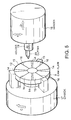
- FIG.5 illustrates a machining apparatus applicable to a method of forming a cam face on a structure member of a loading cam device for a toroidal-type continuously variable transmission.
- a chuck 17 is coaxially fixed to an end portion of a main shaft (spindle) of the machining apparatus so as to be rotatable together with the main shaft in a direction indicated by an arrow C.
- a cam plate 9 being a workpiece is fixed to be coaxially with the chuck 17 and the main shaft in forming a cam face 12.
- the structure of the chuck 17 is similar to a chuck incorporated into an ordinary lathe.
- a header 18 provided in opposed relation to the chuck 17 is displaceable in a direction Z1, i.e., in the axial directions of the chuck 17, and in a direction X, i.e., in the diametrical directions thereof.
- a holder 19 is provided in an end surface of the header 18 to be in confronting relation to the chuck 17, and can be made to withdraw and emerge with respect to the end surface thereof.
- the holder 19 can move or displace in its axial direction Z2.
- a cutter 20 being a cutting tool.
- the holder 19 is displaceable at a high speed and the displacement is controlled by means of a numerical control system.
- the rotation of the main shaft is made to be synchronized with the axial displacement of the holder 19 and, in accordance with the rotation of the chuck 17, the circumferentially extending cross-sectional configuration of the one surface of the cam plate 9 is made to be coincident with the circumferentially extending cross-sectional configuration of the cam face 12 to be formed.
- NC apparatus numerical control apparatus
- the header 18 is displaced in the direction shown in the arrow X, i.e., the diametrical directions of the chuck 17, in FIG.5. Consequently, pluralities of flat portions 14, 14 and concaves 15, 15 are turned out on the cam plate 9, thus forming, thereon, the cam face 12 being an irregular surface circumferentially extending.
- the stroke length S of the holder 19 is required to exceed the step L (see FIG.4, 4 to 5 [mm] for an ordinary toroidal-type continuously variable transmission for ordinary motor vehicles) on the cam face to be formed, i.e., to be "S > L".
- the cam face machining can satisfactorily be put into practical use.
- the rotational speed of the chuck 17 takes a value obtained by dividing the number of times of the follow-up by the number of the concaves 15, 15 making up the cam face 12.
- the rotational speed of the chuck 17 gives 100 to 133 [rpm].
- the rotational speed of the chuck 17 results in being 75 to 100 [rpm].
- the stroke length of the header 18 in the direction X i.e., in the diametric directions of the chuck 17, is set to be greater than the difference between the inner and outer diameters of the cam plate 9 on which the cam face 12 is formed.
- the minimum inner diameter is about 90 [mm] and the maximum outer diameter is about 150 [mm], whereupon the stroke length in the direction X is needed to be over 30 [mm].
- a method of forming a cam face on a structure member of a loading cam device for a toroidal-type continuously variable transmission thus arranged, because the cutter 20 is placed or thrust into one surface of the cam plate 9, on which the cam face 12 is formed, in the axial direction, there results in no elastic deformation of the cutter 20 occurring to affect the manufacturing accuracy if the force placed into the surface is made greater. Therefore, a cutting tool or something having a great flexural rigidity can be used as the cutter 20, besides a small protruding amount from the holder 19 also permits satisfactory machining. Moreover, since the cutter 20 is pressed axially so as to provide a great rigidity, the elastic deformation of the cutter 20 substantially remains within a disregardable range. Accordingly, the cutter 20 can be placed on the one surface of the cam plate 9 at a sufficiently strong force, besides it is possible to ensure a necessary accuracy, improve the manufacturing accuracy and shorten the time taken for the machining of the cam face 12.
- the machining itself of the cam face 12 is based on the cutting machining to remove unnecessary portions of the metallic material, which make it unnecessary to perform the pre-machining for the removal of the surface layer and further to carry out the after-machining for the removal of the excessive thickness portions produced due to the swinging forging.
- the machining process become simplified, thus reducing the manufacturing time as well as reducing the cost required for the formation of the cam face.
- the method according to the present invention permits a surface processing such as a barrel processing for the cam face 12 after the cutting machining without any limitation.
- heat treatment such as curburizing can be made for the cam plate 9 or the input-side disk 2 before the formation of the cam face 12 or 13, if taking the hardness of the cutter 20 into consideration (if using a cutter having a hardness to allow the cutting of a portion hardened by the heat treatment)
- the method of forming a cam face on a structure member of a loading cam device for a toroidal-type continuously variable transmission according to the present invention can also carry out the heat treatment without requiring further conditions other than the condition taken in no heat treatment.
- the method according to the present invention allows the pressing of the cutter 20 against the surface being processed, which permits the formation of the cam face 12 even after the heat treatment. For this reason, the manufacturing cost can sharply be reduced as compared with that in the conventional method wherein the cam face is ground with a whetstone after the heat treatment.
- the numerical control apparatus described above includes a copy shaping control apparatus.
- a method of forming a cam face on a component of a loading cam device for a toroidal-type continuously variable transmission is arranged and works as described above, thus making it possible to ensuring the necessary accuracy as well as forming the cam face at a low cost.
Landscapes
- Engineering & Computer Science (AREA)
- General Engineering & Computer Science (AREA)
- Mechanical Engineering (AREA)
- Friction Gearing (AREA)
Description
Claims (2)
- A method of machining a cam face (12; 13) on a structure member of a loading cam device (8) for a toroidal-type continuously variable transmission, comprising the steps of:rotating said structure member about its own axis, said structure member being incorporated into said loading cam device (8) to be rotatable about its own axis;axially pressing a cutting tool (20) mounted on a holder (19) against one axial surface of said structure member to be machined to have said cam face (12; 13);axially displacing said cutting tool (20) in accordance with a rotational angle of said structure member to form an irregular surface (14, 15, 16) serving as said cam face (12; 13); andforming a circumferentially extending surface (14, 15, 16);wherein said cutting tool (20) is displaced in a diametric direction of said structure member (1; 2) in accordance with the rotational angle of said structure member, wherein the displacement of the axial direction and the diametric direction are controlled by a numerical control system or a copy shaping control system, and wherein a stroke length in the axial direction of said cutting tool (20) is set to exceed a step between a flat portion (14) and concave portion (15) on the cam face (12; 13) to be machined.
- The method as claimed in claim 1, wherein the stroke length in the diametric direction of said cutting tool in the diametric direction of said loading cam device (8) is set to be greater than half of the difference between inner and outer diameters of the structure member of which the cam face (12; 13) is formed.
Applications Claiming Priority (2)
| Application Number | Priority Date | Filing Date | Title |
|---|---|---|---|
| JP202265/94 | 1994-08-26 | ||
| JP6202265A JPH0861452A (en) | 1994-08-26 | 1994-08-26 | Method for forming cam face on member constituting loading cam device for toroidal continuously variable transmission |
Publications (2)
| Publication Number | Publication Date |
|---|---|
| EP0703387A1 EP0703387A1 (en) | 1996-03-27 |
| EP0703387B1 true EP0703387B1 (en) | 1999-01-27 |
Family
ID=16454681
Family Applications (1)
| Application Number | Title | Priority Date | Filing Date |
|---|---|---|---|
| EP95113038A Expired - Lifetime EP0703387B1 (en) | 1994-08-26 | 1995-08-18 | Method for forming cam face on structure member of loading cam device for toroidal-type continuously variable transmission |
Country Status (4)
| Country | Link |
|---|---|
| US (1) | US5669274A (en) |
| EP (1) | EP0703387B1 (en) |
| JP (1) | JPH0861452A (en) |
| DE (1) | DE69507560T2 (en) |
Families Citing this family (5)
| Publication number | Priority date | Publication date | Assignee | Title |
|---|---|---|---|---|
| JP3982104B2 (en) | 1999-03-31 | 2007-09-26 | 日本精工株式会社 | Thrust measurement method of loading cam device for toroidal type continuously variable transmission |
| DE19931087C2 (en) | 1999-07-06 | 2002-07-04 | Nsk Ltd | Cam disc for a continuously variable toroidal gear and method for producing the same |
| JP3849404B2 (en) | 2000-05-25 | 2006-11-22 | 日本精工株式会社 | Loading cam plate for toroidal type continuously variable transmission |
| JP3775660B2 (en) | 2002-01-17 | 2006-05-17 | 日本精工株式会社 | Cage for loading cam device of toroidal type continuously variable transmission |
| JP4748370B2 (en) * | 2006-09-26 | 2011-08-17 | 日本精工株式会社 | Toroidal continuously variable transmission |
Family Cites Families (8)
| Publication number | Priority date | Publication date | Assignee | Title |
|---|---|---|---|---|
| SU588067A1 (en) * | 1976-04-16 | 1978-01-15 | Институт Проблем Надежности И Долговечности Машин Ан Белорусской Сср | Cutting tool |
| US4343206A (en) * | 1980-06-12 | 1982-08-10 | The United States Of America As Represented By The United States Department Of Energy | Slide system for machine tools |
| JPH0672656B2 (en) * | 1989-03-31 | 1994-09-14 | 日産自動車株式会社 | Loading cam device for toroidal continuously variable transmission |
| GB9001906D0 (en) * | 1990-01-27 | 1990-03-28 | Matrix Churchill Limited | Machine tool apparatus |
| US5177842A (en) * | 1990-03-28 | 1993-01-12 | Mitsuba Electric Manufacturing Co. Ltd. | Apparatus for finishing surface of commutator of motor |
| SU1743703A1 (en) * | 1990-10-19 | 1992-06-30 | Одесское специальное конструкторское бюро специальных станков | Method of working profiled end surfaces |
| EP0534740B1 (en) * | 1991-09-27 | 1997-04-23 | Coburn Optical Industries, Inc. | Lathe for generating ophthalmic products from blanks, and a method of operating the lathe |
| US5138894A (en) * | 1992-01-06 | 1992-08-18 | Excelermatic Inc. | Axial loading cam arrangement in or for a traction roller transmission |
-
1994
- 1994-08-26 JP JP6202265A patent/JPH0861452A/en active Pending
-
1995
- 1995-08-16 US US08/515,582 patent/US5669274A/en not_active Expired - Lifetime
- 1995-08-18 EP EP95113038A patent/EP0703387B1/en not_active Expired - Lifetime
- 1995-08-18 DE DE69507560T patent/DE69507560T2/en not_active Expired - Lifetime
Also Published As
| Publication number | Publication date |
|---|---|
| DE69507560T2 (en) | 1999-09-02 |
| DE69507560D1 (en) | 1999-03-11 |
| JPH0861452A (en) | 1996-03-08 |
| EP0703387A1 (en) | 1996-03-27 |
| US5669274A (en) | 1997-09-23 |
Similar Documents
| Publication | Publication Date | Title |
|---|---|---|
| US7118462B2 (en) | Disk for toroidal continuously variable transmission and method of machining the same | |
| JP2000033443A (en) | Spinning method and device therefor | |
| JP2001347443A (en) | Grinding work method of half toroidal cvt disc | |
| CA1176438A (en) | Machine tools | |
| EP0703387B1 (en) | Method for forming cam face on structure member of loading cam device for toroidal-type continuously variable transmission | |
| WO2001026837A1 (en) | Spinning device | |
| EP0791147B1 (en) | Eccentric gear | |
| JP3849404B2 (en) | Loading cam plate for toroidal type continuously variable transmission | |
| US3621617A (en) | Machining apparatus | |
| US7468015B2 (en) | Method for manufacturing a variator component of continuously variable transmission, and variator component of continuously variable transmission | |
| JPH11254258A (en) | Machining jig for constant velocity universal joint | |
| JP4456208B2 (en) | Spinning processing equipment | |
| US6224508B1 (en) | Trunnion of a toroidal continuously variable transmission and manufacturing process thereof | |
| JP3760762B2 (en) | Burnishing device and burnishing method | |
| JP2000061702A (en) | End face machining method of disc for troidal type continuously variable transmission | |
| JP2620186B2 (en) | Continuously variable transmission | |
| SU1256937A1 (en) | Method of working curvilinear components shaped as body of revolution | |
| JPH10156450A (en) | Caulking method and caulking device | |
| JPH10175036A (en) | Conical gear, concaved surface worm and its matching method | |
| JPH04105720A (en) | Manufacture of crown roller | |
| EP0114108A2 (en) | Method for cold sizing a round workpiece having multiple diameters | |
| JP2000202710A (en) | Machining method and device for cam face of loading cam mechanism | |
| JP2022088755A (en) | Support shaft for toroidal-type continuously variable transmission and manufacturing method of support shaft | |
| SU1556881A1 (en) | Arrangement for honing | |
| JPH0199712A (en) | Apparatus for manufacturing internally grooved pipe |
Legal Events
| Date | Code | Title | Description |
|---|---|---|---|
| PUAI | Public reference made under article 153(3) epc to a published international application that has entered the european phase |
Free format text: ORIGINAL CODE: 0009012 |
|
| AK | Designated contracting states |
Kind code of ref document: A1 Designated state(s): DE FR GB |
|
| 17P | Request for examination filed |
Effective date: 19960613 |
|
| 17Q | First examination report despatched |
Effective date: 19970411 |
|
| GRAG | Despatch of communication of intention to grant |
Free format text: ORIGINAL CODE: EPIDOS AGRA |
|
| GRAG | Despatch of communication of intention to grant |
Free format text: ORIGINAL CODE: EPIDOS AGRA |
|
| GRAH | Despatch of communication of intention to grant a patent |
Free format text: ORIGINAL CODE: EPIDOS IGRA |
|
| GRAH | Despatch of communication of intention to grant a patent |
Free format text: ORIGINAL CODE: EPIDOS IGRA |
|
| GRAA | (expected) grant |
Free format text: ORIGINAL CODE: 0009210 |
|
| AK | Designated contracting states |
Kind code of ref document: B1 Designated state(s): DE FR GB |
|
| REF | Corresponds to: |
Ref document number: 69507560 Country of ref document: DE Date of ref document: 19990311 |
|
| ET | Fr: translation filed | ||
| PLBE | No opposition filed within time limit |
Free format text: ORIGINAL CODE: 0009261 |
|
| STAA | Information on the status of an ep patent application or granted ep patent |
Free format text: STATUS: NO OPPOSITION FILED WITHIN TIME LIMIT |
|
| 26N | No opposition filed | ||
| REG | Reference to a national code |
Ref country code: GB Ref legal event code: IF02 |
|
| PGFP | Annual fee paid to national office [announced via postgrant information from national office to epo] |
Ref country code: FR Payment date: 20060426 Year of fee payment: 17 |
|
| PGFP | Annual fee paid to national office [announced via postgrant information from national office to epo] |
Ref country code: GB Payment date: 20080827 Year of fee payment: 14 |
|
| GBPC | Gb: european patent ceased through non-payment of renewal fee |
Effective date: 20090818 |
|
| REG | Reference to a national code |
Ref country code: FR Ref legal event code: ST Effective date: 20100430 |
|
| PG25 | Lapsed in a contracting state [announced via postgrant information from national office to epo] |
Ref country code: FR Free format text: LAPSE BECAUSE OF NON-PAYMENT OF DUE FEES Effective date: 20090831 |
|
| PG25 | Lapsed in a contracting state [announced via postgrant information from national office to epo] |
Ref country code: GB Free format text: LAPSE BECAUSE OF NON-PAYMENT OF DUE FEES Effective date: 20090818 |
|
| PGFP | Annual fee paid to national office [announced via postgrant information from national office to epo] |
Ref country code: DE Payment date: 20140813 Year of fee payment: 20 |
|
| REG | Reference to a national code |
Ref country code: DE Ref legal event code: R071 Ref document number: 69507560 Country of ref document: DE |