EP0702508B1 - Electronic ballast with fuzzy-logic for gas-discharge lamps - Google Patents
Electronic ballast with fuzzy-logic for gas-discharge lamps Download PDFInfo
- Publication number
- EP0702508B1 EP0702508B1 EP95114572A EP95114572A EP0702508B1 EP 0702508 B1 EP0702508 B1 EP 0702508B1 EP 95114572 A EP95114572 A EP 95114572A EP 95114572 A EP95114572 A EP 95114572A EP 0702508 B1 EP0702508 B1 EP 0702508B1
- Authority
- EP
- European Patent Office
- Prior art keywords
- lamp
- ist
- gas discharge
- discharge lamp
- current
- Prior art date
- Legal status (The legal status is an assumption and is not a legal conclusion. Google has not performed a legal analysis and makes no representation as to the accuracy of the status listed.)
- Expired - Lifetime
Links
- 238000000034 method Methods 0.000 claims description 30
- 230000006870 function Effects 0.000 claims description 21
- 238000010438 heat treatment Methods 0.000 claims description 14
- 230000032683 aging Effects 0.000 claims description 11
- 230000008859 change Effects 0.000 claims description 6
- 238000001514 detection method Methods 0.000 claims description 4
- 238000005259 measurement Methods 0.000 claims 4
- 230000007613 environmental effect Effects 0.000 claims 3
- 238000004804 winding Methods 0.000 claims 3
- 230000001419 dependent effect Effects 0.000 claims 2
- 238000009529 body temperature measurement Methods 0.000 claims 1
- 230000001105 regulatory effect Effects 0.000 abstract description 8
- 238000010586 diagram Methods 0.000 description 9
- 230000008901 benefit Effects 0.000 description 8
- 230000008569 process Effects 0.000 description 4
- 238000001816 cooling Methods 0.000 description 3
- 230000005484 gravity Effects 0.000 description 3
- 238000010792 warming Methods 0.000 description 3
- 238000007630 basic procedure Methods 0.000 description 2
- 238000013461 design Methods 0.000 description 2
- 238000011156 evaluation Methods 0.000 description 2
- 230000008447 perception Effects 0.000 description 2
- 238000013459 approach Methods 0.000 description 1
- 238000004364 calculation method Methods 0.000 description 1
- 238000006243 chemical reaction Methods 0.000 description 1
- 230000003247 decreasing effect Effects 0.000 description 1
- 238000009472 formulation Methods 0.000 description 1
- 238000013178 mathematical model Methods 0.000 description 1
- 239000000203 mixture Substances 0.000 description 1
- 230000003287 optical effect Effects 0.000 description 1
- 230000004044 response Effects 0.000 description 1
- 230000035807 sensation Effects 0.000 description 1
- 230000002123 temporal effect Effects 0.000 description 1
- 230000036962 time dependent Effects 0.000 description 1
- 238000013519 translation Methods 0.000 description 1
- 230000001755 vocal effect Effects 0.000 description 1
Images


Classifications
-
- H—ELECTRICITY
- H05—ELECTRIC TECHNIQUES NOT OTHERWISE PROVIDED FOR
- H05B—ELECTRIC HEATING; ELECTRIC LIGHT SOURCES NOT OTHERWISE PROVIDED FOR; CIRCUIT ARRANGEMENTS FOR ELECTRIC LIGHT SOURCES, IN GENERAL
- H05B41/00—Circuit arrangements or apparatus for igniting or operating discharge lamps
- H05B41/14—Circuit arrangements
- H05B41/36—Controlling
- H05B41/38—Controlling the intensity of light
- H05B41/39—Controlling the intensity of light continuously
- H05B41/392—Controlling the intensity of light continuously using semiconductor devices, e.g. thyristor
-
- Y—GENERAL TAGGING OF NEW TECHNOLOGICAL DEVELOPMENTS; GENERAL TAGGING OF CROSS-SECTIONAL TECHNOLOGIES SPANNING OVER SEVERAL SECTIONS OF THE IPC; TECHNICAL SUBJECTS COVERED BY FORMER USPC CROSS-REFERENCE ART COLLECTIONS [XRACs] AND DIGESTS
- Y10—TECHNICAL SUBJECTS COVERED BY FORMER USPC
- Y10S—TECHNICAL SUBJECTS COVERED BY FORMER USPC CROSS-REFERENCE ART COLLECTIONS [XRACs] AND DIGESTS
- Y10S315/00—Electric lamp and discharge devices: systems
- Y10S315/04—Dimming circuit for fluorescent lamps
-
- Y—GENERAL TAGGING OF NEW TECHNOLOGICAL DEVELOPMENTS; GENERAL TAGGING OF CROSS-SECTIONAL TECHNOLOGIES SPANNING OVER SEVERAL SECTIONS OF THE IPC; TECHNICAL SUBJECTS COVERED BY FORMER USPC CROSS-REFERENCE ART COLLECTIONS [XRACs] AND DIGESTS
- Y10—TECHNICAL SUBJECTS COVERED BY FORMER USPC
- Y10S—TECHNICAL SUBJECTS COVERED BY FORMER USPC CROSS-REFERENCE ART COLLECTIONS [XRACs] AND DIGESTS
- Y10S315/00—Electric lamp and discharge devices: systems
- Y10S315/07—Starting and control circuits for gas discharge lamp using transistors
-
- Y—GENERAL TAGGING OF NEW TECHNOLOGICAL DEVELOPMENTS; GENERAL TAGGING OF CROSS-SECTIONAL TECHNOLOGIES SPANNING OVER SEVERAL SECTIONS OF THE IPC; TECHNICAL SUBJECTS COVERED BY FORMER USPC CROSS-REFERENCE ART COLLECTIONS [XRACs] AND DIGESTS
- Y10—TECHNICAL SUBJECTS COVERED BY FORMER USPC
- Y10S—TECHNICAL SUBJECTS COVERED BY FORMER USPC CROSS-REFERENCE ART COLLECTIONS [XRACs] AND DIGESTS
- Y10S706/00—Data processing: artificial intelligence
- Y10S706/90—Fuzzy logic
Definitions
- the present invention relates to an electronic ballast for Gas discharge lamps according to the preamble of claim 1.
- Ballasts are known in the field of electronic ballasts that work with a positively controlled oscillator and are dimmable. For dimming a gas discharge lamp to be connected to the electronic ballast the current flowing through the lamp changes. This is controlled using the Oscillator achieved by changing the lamp current frequency.
- the Gas discharge lamp is controlled via a series resonance circuit in its load circuit. Approximately corresponds to the frequency of the current delivered to the gas discharge lamp the resonance frequency of the series resonance circuit, the lamp is ignited. By Shift the current frequency from the resonance frequency of the series resonant circuit away or to the resonance frequency of the resonant circuit, the current of the Gas discharge lamp can be lowered or increased. To regulate the lamp current the actual value of the current lamp current is measured and with a setpoint compared. A corresponding current controller generates based on these two Values a control value for the current. The lamp voltage is set accordingly Lamp curve on.
- Gas discharge lamps have a negative characteristic. That means that the The lamp voltage drops when the lamp current increases. The lamp should be brighter the current must be regulated up. But it works because of negative characteristic of the lamp counteracts the drop in lamp voltage.
- the lamp current but the Lamp power, d. H. to regulate the product of lamp current and lamp voltage.
- the lamp power is in turn adjusted via the frequency.
- the actual value of the lamp power is measured and compared with a target value.
- the frequency depends on the sign of the control difference from the resonance frequency of the one present in the load circuit of the lamp Series resonance circuit away or shifted to the resonance frequency.
- Such Ballasts have the disadvantage that only the lamp power can be monitored. Because only the product of lamp voltage and lamp current is regulated, it is not excluded that the electronic ballast may be in an unstable or prohibited range is controlled. For example conceivable that a limit value for the maximum permissible lamp power is maintained is exceeded, however, a limit value for a maximum permissible lamp current becomes.
- the invention has for its object an improved electronic Ballast for gas discharge lamps to specify, which in particular the avoids disadvantages explained above.
- fuzzy logic control technology i.e. the The brightness of the connected gas discharge lamp is controlled by a fuzzy controller regulated that, depending on at least one input variable, a manipulated variable for a physical size of the inverter or the load circuit of the electronic Ballast generated.
- the lamp current is preferably regulated, i.e. the The actual value of the lamp current is recorded and fed to a comparator which measures the actual value with a specified target value and compares the resulting control difference passes on to the fuzzy controller.
- the fuzzy controller generates according to the rules of Fuzzy logic depending on the control difference a control signal for the Inverter or the load circuit.
- the control signal of the Fuzzy controller the frequency or the duty cycle of the lamp current or the Lamp voltage set.
- the fuzzy controller ensures by setting up Decision rules, into which corresponding empirical values can flow, that the Lamp is not controlled in unstable areas.
- the Ambient temperature and / or the filament resistance of the gas discharge lamp is detected and be fed to the fuzzy controller.
- the Fuzzy controller in connection with the detected lamp voltage a statement about make the degree of aging of the connected gas discharge lamp.
- the setpoint signal of the comparator of the control device can be external, e.g. be changeable via a dimmer and also stored as a predetermined fixed value.
- the fuzzy controller as exponential or logarithmic function element, so that between the Output variable of the fuzzy controller and its input variable an exponential or there is a logarithmic relationship. This is - as explained below will be - particularly advantageous to a linear relationship between the of the brightness output received by the gas discharge lamp and that of the To create observers subjectively perceived brightness.
- a special feature of fuzzy logic is that not all input variables are used for Obtaining the output variable must be evaluated.
- Reaches e.g. one or the fuzzy controller sets several of the input variables regardless of the remaining input variables, the output variable to one certain value.
- the output value of the fuzzy controller depends only on the Design of the decision rules, i.e. the so-called fuzzy rules.
- the fuzzy logic is also advantageous for detecting the lamp type connected gas discharge lamp used. From EP-A-0 413 991 it is known to determine the ignition voltage of the connected gas discharge lamp and on the basis the determined ignition voltage to infer the lamp type. The determination of Ignition voltage depends, among other things, on the manufacturer, the degree of aging Gas filling and the heating of the lamp, so that there are overall fluctuations in Range between 10% and 20% when determining the ignition voltage.
- Claim 13 specifies a new method, by means of which by determining at least one operating parameter after startup of the gas discharge lamp Lamp type can be determined.
- the solution according to the invention has the advantage on that several different operating parameters for evaluating the lamp type can be used, the different volatility exhibit. For this reason, it is advantageous to determine the lamp type Fuzzy logic is used because of the free design of the fuzzy rules allows the individual operating parameters to be evaluated individually or in combination. A corresponding solution is given in claim 14.
- the lamp type of the connected gas discharge lamp has been determined, then this preferably in a memory in the form of various operating parameters or stored in the form of the corresponding lamp characteristic so that the lamp type does not have to be constantly checked and determined as long as the corresponding one Gas discharge lamp has not been replaced.
- the lamp can be replaced determined by detecting a possible break in the heating circuit become.
- the corresponding controller of the electronic controls Ballast the brightness of the connected gas discharge lamp in Depending on their type.
- the type of lamp found is optical and / or indicated acoustically so that the user is constantly aware of the type of lamp used.
- an electronic ballast for Gas discharge lamps used the fuzzy logic.
- Fuzzy logic The generally valid statements of Fuzzy logic will be briefly described below.
- Fuzzy logic is logic that works with imprecise statements.
- the single ones Quantities of the fuzzy logic are quantified, i.e. it is for each size only certain value ranges permitted.
- the individual sizes are quantified according to so-called membership functions, the current value being one Input variable of the fuzzy logic a corresponding value range according to its Affiliation function and a corresponding truth value (degree of fulfillment) is assigned.
- the quantified input variables are with their Truth values combined according to certain decision rules, so that a - likewise quantified - output variable of the fuzzy logic system can be derived can.
- the quantified output variable is then converted into a concrete one Output variable converted according to a certain method.
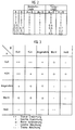
- the heating of a room depends on the interior and Outside temperature of the room should be regulated.
- the two input variables i.e. the inside and outside temperature
- the Output variable i.e. for example the control value for the temperature of the Boiler
- everyone Size is assigned only five ranges of values, according to their corresponding Membership function are delimited from each other.
- the course of the membership functions is by no means mandatory.
- the individual areas can optionally also be non-overlapping and triangular.
- a concrete input value of the fuzzy controller is now based on its corresponding one Membership function assigned to one or more of the areas, depending on whether the areas for the concrete input value overlap or not. Of further is for the concrete input value and for each of its assigned Areas a corresponding truth value or degree of fulfillment.
- the output variable of the controller is also quantified, ie divided into certain value ranges.
- the identifiers label
- strong heating "slight heating”
- Constant “slight cooling”
- strong cooling are available for the output variable, which are each defined between specific temperature limits. The individual temperature limits are determined based on certain empirical values. If the designation for the output variable is "slight cooling” with a truth value of 1.0, this would mean the manipulated variable T 4 for the heating. If the output variable has a correspondingly low truth value, the control value for the heating changes according to the membership function C.
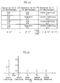
- the fuzzy logic provides the minimum value of the for an AND combination of the input variables two input variables and for an OR combination the maximum value of the two Input variables, so that in principle the fuzzy logic corresponds to the Boolean logic, but with the exception that the fuzzy logic also contains unsharp values between 0 and 1 can combine with each other.
- the individual value pairs of the input variables A and B which correspond to the Affiliation functions in Figure 1 are now obtained after certain rules, the so-called fuzzy rules, combined with each other.
- fuzzy rules For each a combination of a pair of values of input variable A with a pair of values the input variable B results in a certain quantified output variable C.
- the Individual fuzzy rules are set up based on certain empirical values. On the corresponding combination diagram is shown in FIG. 3 with the associated legend. The assignment of a specific identifier of the output variable C to one certain combination of input variables A and B is initially without Consideration of the corresponding truth values.
- the truth value corresponds to the quantified one Output variable C the minimum of the two truth values of each other Combined input variables A and B.
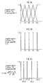
- Figure 4a four pairs of values for the output variable C received.
- the last remaining step to determine a concrete manipulated variable for the Heating is the implementation of the four pairs of values of the quantified output variable C in a specific controller manipulated variable.
- the four different ones Value pairs of the output variable C combined with each other to a specific one to receive a concrete manipulated variable. This process is called defuzzification.
- Figure 4b is intended to illustrate the operation of this method.
- the associated truth values are applied to the individual identifiers of the output variable C.
- the identifier "strong warming” with a truth value of 0.7 was obtained once for the quantified initial variable C and three times the identifier "slight warming" with a truth value of 0.3 each.
- the remaining identifiers of the associated membership function C have not been determined, which corresponds to a truth value 0 for these identifiers.
- the calculated center of gravity corresponds to the concrete manipulated variable for the boiler temperature. If, for example, it is assumed that T 1 corresponds to a heating boiler temperature of 80 ° C and T 2 corresponds to a heating boiler temperature of 70 ° C, the control value for the heating boiler temperature would be 74 ° C.
- the inventive method results electronic ballast compared to the known electronic ballast a number of advantages.
- the main advantages of fuzzy logic are for example in "Fuzzy logic, the fuzzy logic conquers technology", Daniel McNeill and Paul Freiberger, Droemer Knaur Verlag, 1994. So points for example, the logic control over digital control has the advantage that a possibly existing control difference is gradually reduced, while at comparable digital controllers often exceed or fall below the target value is so that this overregulation must be quickly compensated for.
- the fuzzy logic can be used in particular when igniting gas discharge lamps become. Gas discharge lamps are made by approximating the frequency of the Lamp current to the resonance frequency of the existing in the load circuit Series resonance circuit switched on or ignited. Should the lamp after Turn on to operate at a low brightness, so it is necessary after switch the brightness of the lamp down quickly when switching on, whereby at ordinary systems undershoot below the desired brightness occur what in the worst case, the lamp can go out.
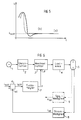
- FIG. 5 shows (a) the time-dependent characteristic of the lamp brightness E during an ignition process of the gas discharge lamp. It can be seen that while the lamp brightness is being reduced, the target brightness E target is fallen short of, so that compensation control is necessary to achieve the target value. With the fuzzy logic, on the other hand, an improved approach to the desired brightness value is possible without overshoot or undershoot. For comparison, FIG. 5 shows the brightness characteristic curve (b) that can be achieved with a fuzzy controller.
- fuzzy logic enables a particularly fast response or Setting the output size possible so that when using a fuzzy controller an existing control difference, as can also be seen in FIG. 5, is compensated more quickly can be.
- Other advantages of fuzzy logic can be seen in the fact that compared less information is required about known control systems and additionally this Verbal formulations can be found immediately because the Fuzzy logic works with linguistic terms. For this reason, too human knowledge is brought into the system in the simplest way, without translation into complex mathematical models.
- FIG. 6 shows a first Embodiment of the ballast according to the invention.
- the electronic ballast comprises a rectifier 2, which is fed by a supply voltage source 1 and is connected to an inverter 3.
- a load circuit 4 is connected to the inverter 3, which serves to control a gas discharge lamp 5 and usually contains, inter alia, a series resonance circuit for igniting the connected gas discharge lamp 5.
- the electronic ballast comprises a control device which comprises a controller 7 and a comparator 6.
- the controller 7 is designed as a fuzzy controller.
- the control device can be arranged in the electronic ballast or also externally.
- the lamp current of the connected gas discharge lamp 5 is preferably regulated.
- the lamp current is detected by a current measuring element 8 and the instantaneous actual value of the lamp current i is output to the comparator 6 of the control device.
- the comparator 6 compares the actual value i ist of the lamp current with a predetermined lamp current setpoint i soll , the current setpoint i soll corresponding to a predetermined dimming setpoint, which is output, for example, by a dimmer to the comparator 6.
- Be the current target value i soll or the predetermined dimming setpoint can be changed in both time manually, as is the case with ordinary Dimm healthyen, as well as present an invariable fixed value, for example, stored in the form.
- the comparator 6 determines a control difference value i diff , which is applied to the fuzzy controller 7, on the basis of the comparison of the current setpoint i soll with the actual value i ist .
- the fuzzy controller generates a control value y for the inverter 3 depending on the input variable i diff.
- the lamp brightness is usually set by adjusting the frequency f or the pulse duty factor d of the lamp current of the connected gas discharge lamp 5.
- the fuzzy controller can also be used to regulate the lamp voltage or lamp power.
- a voltage measuring element 9 is provided which detects the instantaneous lamp voltage and generates an actual value of the lamp voltage u ist .
- the lamp voltage actual value signal u ist determined by the voltage measuring element 9 is then applied to the comparator 6 instead of the lamp current actual value signal i ist and compared there with a voltage target value, the comparator 6 then correspondingly Control difference signal of the voltage to the fuzzy controller.
- the current control as shown in FIG. 6, represents the common type of control.
- the reason for this can be seen in the fact that, due to the negative characteristic curve of the lamp, a plurality of lamp current values can be assigned for one lamp voltage value, so that ambiguities would arise in the case of voltage regulation. In contrast, there is only a single lamp voltage value for each lamp current value, so that ambiguities are avoided with the aid of the current control.
- the lamp voltage u detected by the voltage measuring element 9 is to be applied directly to the fuzzy controller 7 as a further input variable of the fuzzy controller 7.
- the fuzzy controller 7 combines the two input values i diff and u which are present in fuzz repeater form, and determines capped decision rules based on previously a corresponding control value signal y for the inverter 3 or the load circuit 4 of the electronic ballast. Due to the properties of the fuzzy logic described above, in contrast to conventional controllers, it is possible in principle to evaluate certain input variables and to combine them, whereby neither the input variables nor the output variable need to belong to the same physical variable (eg current or voltage).
- FIG. 7 shows a further exemplary embodiment, which differs from the first exemplary embodiment shown in FIG. 6 in that, as already described above, the lamp voltage is also monitored by a voltage measuring element 9 and a corresponding actual lamp voltage value u is applied to the fuzzy Controller 7 is created as an additional input variable. Furthermore, in FIG. 7, the fuzzy controller 7 generates a further output signal z in addition to the control value y for the inverter 3. In the drawing, the corresponding parts of the block diagrams are identified by identical reference numerals. In the second exemplary embodiment shown in FIG. 7, the fuzzy controller 7 can draw conclusions about the aging of the connected gas discharge lamp 5 with the aid of the supplied voltage u ist .
- the fuzzy controller assigns each fuzzified lamp voltage value u is a corresponding degree of aging on the basis of previously established decision rules, the degrees of aging also being present in fuzzified form. After defuzzification of the degree of aging has taken place, ie the conversion of the fuzzified degree of aging into a concrete aging value, the fuzzy controller 7 outputs the corresponding output signal z. Furthermore, the feedback voltage u ist can also be used for constant regulation of the lamp power. The lamp voltage of the gas discharge lamp 5 changes depending on the ambient temperature, so that it is necessary for constant regulation of the lamp power, depending on the instantaneous lamp voltage u , the current value has to be increased or decreased.
- the brightness of the connected gas discharge lamp is approximately proportional to the lamp power.
- FIG. 7 it is also indicated that, in addition to the control difference value i diff, alternatively or alternatively also its temporal gradient i ' diff , ie the change in the control difference i diff over time , can be fed to the fuzzy controller 7, since, for example, also when the degree of aging is detected of the connected gas discharge lamp are interested in the rate of change of the lamp current over time and can accordingly be used to determine the degree of aging.
- the output variable Y does not become inherent overlapping value ranges, but by individual, discrete values, so-called Singletons, each modeled with the truth value 1.0.
- the values of the singletons result from inserting the maximum values of the value ranges of the input variable X into the function to be described by the fuzzy component.
- the straight line equation we get for the singletons have the same values as for the maximum values of the value ranges of the Input variable X.
- Figure 9 shows a third embodiment of the invention according to the invention, at that in connection with an electronic ballast for a Gas discharge lamp use is made of the fuzzy logic.
- the exemplary embodiment shown in FIG. 9 is independent of the fuzzy logic the inventive idea is based on different operating parameters of the connected gas discharge lamp after commissioning to the lamp type to close the gas discharge lamp 5.
- the ignition voltage of a connected gas discharge lamp determine and infer the lamp type based on the determined ignition voltage.
- the determination of the ignition voltage depends on many different ones Requirements or parameters, so that the ignition voltage is only inaccurate can be determined.
- the invention proposes at least one Determine the operating parameters of the lamp after its commissioning and on the basis of this operating parameter to infer the lamp type.
- the basic procedure for lamp detection is briefly described below described. It is assumed that the Control device to be controlled physical quantity is the lamp current. To Commissioning of the gas discharge lamp will have different lamp current setpoints specified and the lamp current set according to these setpoints. To each Lamp current setpoint becomes the corresponding actual value of those to be monitored Operating size of the gas discharge lamp determined. The individual thus preserved Actual values of the operating variables are combined with one another, so that subsequently on the basis of the actual values depending on the specified lamp current setpoints Lamp type of the connected gas discharge lamp can be closed. To This purpose is, for example, the evaluation of various predefined ones Characteristic curves of the individual lamp types conceivable. For example, the Current / voltage characteristics of different lamp types can be known. As before different current setpoints are set and accordingly the Lamp voltage determined depending on the set current setpoints. Based the determined current / voltage value pairs and the various existing ones Current / voltage characteristics can be based on the lamp type of the connected Gas discharge lamp can be closed.
- fuzzy logic is advantageously used for the evaluation of individual operating parameter values or different operating parameters in combination.
- a corresponding embodiment is shown in FIG 9.
- the fuzzy logic component 14 specifies current setpoints for setting the lamp current to a control device and detects the actual values R ist , u ist and T ist depending on the set current setpoints. In this way, several actual lamp values R ist , u ist and T ist are assigned to several lamp current values that have been set.
- the controller 7 shown in Figure 9 can also be implemented as a fuzzy controller, in which a supply of the lamp voltage detected is u is as further input variable of the fuzzy controller for more precise control of the lamp current of advantage.
- a supply of the lamp voltage detected is u is as further input variable of the fuzzy controller for more precise control of the lamp current of advantage.
- the fuzzy logic component 14 is the respective (fuzz er) in quantified form the present actual values of the monitored operating variables R, u and T is according to the procedure of Fuzzy logic assigns a corresponding lamp type.
- the decision rules were preferably established on the basis of known characteristic curves of the different lamp types.
- FIG. 10 shows an example of the assignment of the lamp type to the detected actual values of the outside temperature T ist , the filament resistance R ist and the lamp voltage u ist , different current-voltage characteristics being shown for different lamp types.
- the characteristics shown show the current-voltage characteristics of three different lamp types for the temperature range T ist ⁇ 25 ° C and for a filament resistance R ist below a certain limit. For other areas of the temperature T ist and the coil resistance R ist , further characteristic curves are recorded or are already available.
- the voltage range of the lamp voltage u L is divided into several ranges U 1 to U 5 , ie quantified or fuzzified.
- a memory 13 is advantageous with the fuzzy logic 14 connected so that after determining the lamp type, this lamp type for example in the form of the corresponding lamp characteristic or in the form of various operating parameter values can be stored in the memory.
- this lamp type for example in the form of the corresponding lamp characteristic or in the form of various operating parameter values can be stored in the memory.
- the lamp type can also be indicated acoustically or optically be so that the user during the operation of a gas discharge lamp the connected lamp type is constantly informed.
- According to the invention continues proposed to delete the memory after each lamp change. So can for example by detecting an interruption in the heating circuit Gas discharge lamp using a heating current measuring element 12 detects a lamp change and then the memory will be deleted.
- said fuzzy logic component 14 defines a respective current target value i soll according to the determined lamp type to the comparator 6 of the control device.
Landscapes
- Circuit Arrangements For Discharge Lamps (AREA)
Abstract
Description
Die vorliegende Erfindung betrifft ein elektronisches Vorschaltgerät für
Gasentladungslampen nach dem Oberbegriff des Patentanspruches 1.The present invention relates to an electronic ballast for
Gas discharge lamps according to the preamble of
Auf dem Gebiet der elektronischen Vorschaltgeräte sind Vorschaltgeräte bekannt, die mit einem zwangsgesteuerten Oszillator arbeiten und dimmbar sind. Zur Dimmung einer an das elektronische Vorschaltgerät anzuschließenden Gasentladungslampe wird der durch die Lampe fließende Strom verändert. Dies wird mithilfe des gesteuerten Oszillators durch Verändern der Lampenstromfrequenz erreicht. Die Gasentladungslampe wird über einen Serienresonanzkreis in ihrem Lastkreis gesteuert. Entspricht die Frequenz des an die Gasentladungslampe abgegebenen Stromes in etwa der Resonanzfrequenz des Serienresonanzkreises, so wird die Lampe gezündet. Durch Verschieben der Stromfrequenz von der Resonanzfrequenz des Serienschwingkreises weg bzw. zur Resonanzfrequenz des Schwingkreises hin kann der Strom der Gasentladungslampe erniedrigt bzw. erhöht werden. Zur Regelung des Lampenstromes wird der Istwert des aktuellen Lampenstromes gemessen und mit einem Sollwert verglichen. Ein entsprechend vorhandener Stromregler erzeugt aufgrund dieser beiden Werte einen Stellwert für den Strom. Die Lampenspannung stellt sich entsprechend der Lampenkennlinie ein.Ballasts are known in the field of electronic ballasts that work with a positively controlled oscillator and are dimmable. For dimming a gas discharge lamp to be connected to the electronic ballast the current flowing through the lamp changes. This is controlled using the Oscillator achieved by changing the lamp current frequency. The Gas discharge lamp is controlled via a series resonance circuit in its load circuit. Approximately corresponds to the frequency of the current delivered to the gas discharge lamp the resonance frequency of the series resonance circuit, the lamp is ignited. By Shift the current frequency from the resonance frequency of the series resonant circuit away or to the resonance frequency of the resonant circuit, the current of the Gas discharge lamp can be lowered or increased. To regulate the lamp current the actual value of the current lamp current is measured and with a setpoint compared. A corresponding current controller generates based on these two Values a control value for the current. The lamp voltage is set accordingly Lamp curve on.
Gasentladungslampen weisen eine negative Kennlinie auf. Das heißt, daß die Lampenspannung sinkt, wenn der Lampenstrom steigt. Soll die Lampe heller geregelt werden, so muß der Strom hochgeregelt werden. Dem wirkt aber aufgrund der negativen Kennlinie der Lampe das Abfallen der Lampenspannung entgegen.Gas discharge lamps have a negative characteristic. That means that the The lamp voltage drops when the lamp current increases. The lamp should be brighter the current must be regulated up. But it works because of negative characteristic of the lamp counteracts the drop in lamp voltage.
Aus diesem Grunde wurde vorgeschlagen, nicht den Lampenstrom, sondern die Lampenleistung, d. h. das Produkt aus Lampenstrom und Lampenspannung, zu regeln. Die Einstellung der Lampenleistung erfolgt dabei wiederum über die Frequenz. Der Istwert der Lampenleistung wird gemessen und mit einem Sollwert verglichen. Um einen Ausgleich der Regeldifferenz, d.h. der Differenz zwischen dem Istwert und dem Sollwert, zu erzielen, wird die Frequenz abhängig vom Vorzeichen der Regeldifferenz von der Resonanzfrequenz des im Lastkreis der Lampe vorhandenen Serienresonanzkreises weg bzw. zu der Resonanzfrequenz hin verschoben. Derartige Vorschaltgeräte weisen jedoch den Nachteil auf, daß lediglich die Lampenleistung überwacht werden kann. Da nur das Produkt aus Lampenspannung und Lampenstrom geregelt wird, ist nicht ausgeschlossen, daß das elektronische Vorschaltgerät ggf. in einen instabilen oder nicht zulässigen Bereich gesteuert wird. So ist beispielsweise denkbar, daß ein Grenzwert für die maximal zulässige Lampenleistung eingehalten wird, jedoch ein Grenzwert für einen maximal zulässigen Lampenstrom überschritten wird.For this reason, it was suggested not the lamp current, but the Lamp power, d. H. to regulate the product of lamp current and lamp voltage. The lamp power is in turn adjusted via the frequency. The The actual value of the lamp power is measured and compared with a target value. Around compensation of the control difference, i.e. the difference between the actual value and the To achieve the desired value, the frequency depends on the sign of the control difference from the resonance frequency of the one present in the load circuit of the lamp Series resonance circuit away or shifted to the resonance frequency. Such Ballasts, however, have the disadvantage that only the lamp power can be monitored. Because only the product of lamp voltage and lamp current is regulated, it is not excluded that the electronic ballast may be in an unstable or prohibited range is controlled. For example conceivable that a limit value for the maximum permissible lamp power is maintained is exceeded, however, a limit value for a maximum permissible lamp current becomes.
Der Erfindung liegt die Aufgabe zugrunde, ein verbessertes elektronisches Vorschaltgerät für Gasentladungslampen anzugeben, welches insbesondere die vorstehend erläuterten Nachteile vermeidet.The invention has for its object an improved electronic Ballast for gas discharge lamps to specify, which in particular the avoids disadvantages explained above.
Die Aufgabe wird erfindungsgemäß durch ein elektronisches Vorschaltgerät nach
Anspruch 1 mit den im Kennzeichen des Anspruches 1 angegebenen Merkmalen gelöst.According to the invention, the object is achieved by an
Erfindungsgemäß wird von der Fuzzy-Logik-Regeltechnik Gebrauch gemacht, d.h. die Helligkeit der angeschlossenen Gasentladungslampe wird von einem Fuzzy-Regler geregelt, der abhängig von mindestens einer Eingangsgröße einen Stellwert für eine physikalische Größe des Wechselrichters oder des Lastkreises des elektronischen Vorschaltgeräts erzeugt. Vorzugsweise wird dabei der Lampenstrom geregelt, d.h. der Istwert des Lampenstromes wird erfaßt, einem Vergleicher zugeführt, der den Istwert mit einem vorgegebenen Sollwert vergleicht und die daraus gewonnene Regeldifferenz an den Fuzzy-Regler weitergibt. Der Fuzzy-Regler erzeugt gemäß den Regeln der Fuzzy-Logik abhängig von der Regeldifferenz ein Stellwertsignal für den Wechselrichter oder den Lastkreis. Vorzugsweise wird durch das Stellwertsignal des Fuzzy-Reglers die Frequenz oder das Tastverhältnis des Lampenstromes oder der Lampenspannung eingestellt. Der Fuzzy-Regler gewährleistet durch Aufstellen von Entscheidungs-Regeln, in die entsprechende Erfahrungswerte einfließen können, daß die Lampe nicht in instabile Bereiche gesteuert wird.According to the invention, use is made of fuzzy logic control technology, i.e. the The brightness of the connected gas discharge lamp is controlled by a fuzzy controller regulated that, depending on at least one input variable, a manipulated variable for a physical size of the inverter or the load circuit of the electronic Ballast generated. The lamp current is preferably regulated, i.e. the The actual value of the lamp current is recorded and fed to a comparator which measures the actual value with a specified target value and compares the resulting control difference passes on to the fuzzy controller. The fuzzy controller generates according to the rules of Fuzzy logic depending on the control difference a control signal for the Inverter or the load circuit. The control signal of the Fuzzy controller the frequency or the duty cycle of the lamp current or the Lamp voltage set. The fuzzy controller ensures by setting up Decision rules, into which corresponding empirical values can flow, that the Lamp is not controlled in unstable areas.
Anstelle der Stromregelung ist auch eine Spannungs- oder Leistungsregelung denkbar.Instead of current regulation, voltage or power regulation is also conceivable.
Für eine umfassende Regelung der Lampenhelligkeit können des weiteren die Umgebungstemperatur und/oder der Wendelwiderstand der Gasentladungslampe erfaßt und dem Fuzzy-Regler zugeführt werden. Mithilfe dieser Informationen kann der Fuzzy-Regler im Zusammenhang mit der erfaßten Lampenspannung eine Aussage über den Alterungsgrad der angeschlossenen Gasentladungslampe machen.For a comprehensive control of the lamp brightness, the Ambient temperature and / or the filament resistance of the gas discharge lamp is detected and be fed to the fuzzy controller. Using this information, the Fuzzy controller in connection with the detected lamp voltage a statement about make the degree of aging of the connected gas discharge lamp.
Das Sollwertsignal des Vergleichers der Regeleinrichtung kann sowohl extern, z.B. über einen Dimmer, veränderbar als auch als vorgegebener Festwert gespeichert sein. The setpoint signal of the comparator of the control device can be external, e.g. be changeable via a dimmer and also stored as a predetermined fixed value.
Des weiteren wird erfindungsgemäß vorgeschlagen, den Fuzzy-Regler als exponentielles oder logarithmisches Funktionsglied einzusetzen, so daß zwischen der Ausgangsgröße des Fuzzy-Reglers und seiner Eingangsgröße ein exponentieller bzw. logarithmischer Zusammenhang besteht. Dies ist - wie noch nachfolgend erläutert werden wird - besonders vorteilhaft, um einen linearen Zusammenhang zwischen der von der Gasentladungslampe aufgenommenen Helligkeitsleistung und der vom Beobachter subjektiv empfundenen Helligkeit herzustellen.Furthermore, it is proposed according to the invention to use the fuzzy controller as exponential or logarithmic function element, so that between the Output variable of the fuzzy controller and its input variable an exponential or there is a logarithmic relationship. This is - as explained below will be - particularly advantageous to a linear relationship between the of the brightness output received by the gas discharge lamp and that of the To create observers subjectively perceived brightness.
Eine Besonderheit der Fuzzy-Logik liegt darin, daß nicht sämtliche Eingangsgrößen zur Gewinnung der Ausgangsgröße ausgewertet werden müssen. Erreicht z.B. eine oder mehrere der Eingangsgrößen einen vorgebenen Grenzwert, so stellt der Fuzzy-Regler unabhängig von den restlichen Eingangsgrößen die Ausgangsgröße auf einen bestimmten Wert ein. Der Ausgangswert des Fuzzy-Reglers hängt lediglich von der Gestaltung der Entscheidungsregeln, d.h. den sogenannten Fuzzy-Regeln, ab.A special feature of fuzzy logic is that not all input variables are used for Obtaining the output variable must be evaluated. Reaches e.g. one or the fuzzy controller sets several of the input variables regardless of the remaining input variables, the output variable to one certain value. The output value of the fuzzy controller depends only on the Design of the decision rules, i.e. the so-called fuzzy rules.
Vorteilhaft wird des weiteren die Fuzzy-Logik auch zur Erkennung des Lampentyps der angeschlossenen Gasentladungslampe eingesetzt. Aus der EP-A-0 413 991 ist bekannt, die Zündspannung der angeschlossenen Gasentladungslampe zu ermitteln und aufgrund der ermittelten Zündspannung auf den Lampentyp zu schließen. Die Bestimmung der Zündspannung hängt jedoch unter anderem vom Hersteller, dem Alterungsgrad, der Gasfüllung und der Heizung der Lampe ab, so daß sich insgesamt Schwankungen im Bereich zwischen 10% und 20% beim Ermitteln der Zündspannung ergeben können.The fuzzy logic is also advantageous for detecting the lamp type connected gas discharge lamp used. From EP-A-0 413 991 it is known to determine the ignition voltage of the connected gas discharge lamp and on the basis the determined ignition voltage to infer the lamp type. The determination of Ignition voltage depends, among other things, on the manufacturer, the degree of aging Gas filling and the heating of the lamp, so that there are overall fluctuations in Range between 10% and 20% when determining the ignition voltage.
Anspruch 13 gibt ein neues Verfahren an, mit dessen Hilfe durch Ermitteln von
mindestens einem Betriebsparameter nach Inbetriebnahme der Gasentladungslampe der
Lampentyp festgestellt werden kann. Die erfindungsgemäße Lösung weist den Vorteil
auf, daß mehrere unterschiedliche Betriebsparameter zur Auswertung des Lampentyps
herangezogen werden können, die unterschiedliche Schwankungsanfälligkeiten
aufweisen. Vorteilhaft wird aus diesem Grund zum Ermitteln des Lampentyps die
Fuzzy-Logik eingesetzt, die es aufgrund der freien Gestaltung der Fuzzy-Regeln
erlaubt, die einzelnen Betriebsparameter einzeln oder in Kombination auszuwerten. Eine
entsprechende Lösung wird in Anspruch 14 angegeben.
Wurde der Lampentyp der angeschlossenen Gasentladungslampe festgestellt, so wird dieser vorzugsweise in einem Speicher in Form von verschiedenen Betriebsparametern oder in Form der entsprechenden Lampenkennlinie gespeichert, so daß der Lampentyp nicht ständig überprüft und ermittelt werden muß, solange die entsprechende Gasentladungslampe nicht ausgewechselt worden ist. Ein Austauschen der Lampe kann dabei durch Erfassen einer eventuellen Unterbrechung des Heizstromkreises ermittelt werden.If the lamp type of the connected gas discharge lamp has been determined, then this preferably in a memory in the form of various operating parameters or stored in the form of the corresponding lamp characteristic so that the lamp type does not have to be constantly checked and determined as long as the corresponding one Gas discharge lamp has not been replaced. The lamp can be replaced determined by detecting a possible break in the heating circuit become.
Nach Feststellen des Lampentyps regelt der entsprechende Regler des elektronischen Vorschaltgerätes die Helligkeit der angeschlossenen Gasentladungslampe in Abhängigkeit von deren Typ. Idealerweise wird der festgestellte Lampentyp optisch und/oder akustisch angezeigt, so daß der Benutzer ständig Kenntnis über den eingesetzten Lampentyp besitzt.After determining the lamp type, the corresponding controller of the electronic controls Ballast the brightness of the connected gas discharge lamp in Depending on their type. Ideally, the type of lamp found is optical and / or indicated acoustically so that the user is constantly aware of the type of lamp used.
Weitere vorteilhafte Ausgestaltungen der Erfindung sind in den übrigen Unteransprüchen angegeben.Further advantageous embodiments of the invention are in the rest Subclaims specified.
Die Erfindung wird nachfolgend unter Bezugnahme auf die Zeichnung näher
beschrieben. Es zeigen:
Die Erfindung wird nachstehend anhand bevorzugter Ausführungsbeispiele unter Bezugnahme auf die Zeichnung näher beschrieben.The invention is described below on the basis of preferred exemplary embodiments Described in more detail with reference to the drawing.
Wie zuvor erwähnt, wird erfindungsgemäß in einem elektronischen Vorschaltgerät für Gasentladungslampen die Fuzzy-Logik eingesetzt. Die allgemein gültigen Aussagen der Fuzzy-Logik sollen im folgenden kurz dargestellt werden.As mentioned above, according to the invention, an electronic ballast for Gas discharge lamps used the fuzzy logic. The generally valid statements of Fuzzy logic will be briefly described below.
Fuzzy-Logik ist eine Logik, die mit unpräzisen Aussagen arbeitet. Die einzelnen Größen der Fuzzy-Logik werden quantifiziert, d.h. es sind für jede Größe nur bestimmte Wertebereiche zugelassen. Die Quantifizierung der einzelnen Größen erfolgt nach sogenannten Zugehörigkeitsfunktionen, wobei dem aktuellen Wert einer Eingangsgröße der Fuzzy-Logik ein entsprechender Wertebereich gemäß seiner Zugehörigkeitsfunktion und ein entsprechender Wahrheitswert (Erfüllungsgrad) zugewiesen wird. Die quantifizierten Eingangsgrößen werden mit ihren Wahrheitswerten entsprechend bestimmter Entscheidungsregeln kombiniert, so daß eine - ebenfalls quantifizierte - Ausgangsgröße des Fuzzy-Logik-Systems abgeleitet werden kann. Die quantifizierte Ausgangsgröße wird abschließend in eine konkrete Ausgangsgröße nach einer bestimmten Methode umgewandelt.Fuzzy logic is logic that works with imprecise statements. The single ones Quantities of the fuzzy logic are quantified, i.e. it is for each size only certain value ranges permitted. The individual sizes are quantified according to so-called membership functions, the current value being one Input variable of the fuzzy logic a corresponding value range according to its Affiliation function and a corresponding truth value (degree of fulfillment) is assigned. The quantified input variables are with their Truth values combined according to certain decision rules, so that a - likewise quantified - output variable of the fuzzy logic system can be derived can. The quantified output variable is then converted into a concrete one Output variable converted according to a certain method.
Die prinzipielle Vorgehensweise der Fuzzy-Logik soll nun anhand des Beispieles einer Temperaturregelung, wie sie beispielsweise im Bericht "Technology Profile Fuzzy Logic", Marcello Hoffmann, SRI International, Juni 1994, beschrieben ist, erläutert werden.The basic procedure of the fuzzy logic is now based on the example of a Temperature control, as described, for example, in the report "Technology Profile Fuzzy Logic ", Marcello Hoffmann, SRI International, June 1994 become.
Es sei angenommen, daß die Heizung eines Zimmers abhängig von der Innen- und Außentemperatur des Zimmers geregelt werden soll. Wie in Figur 1 gezeigt, werden die beiden Eingangsgrößen, d.h. die Innen- und Außentemperatur, und die Ausgangsgröße, d.h. beispielsweise der Stellwert für die Temperatur des Heizungskessels, nach entsprechenden Zugehörigkeitsfunktionen quantifiziert. Jeder Größe sind lediglich fünf Wertebereiche zugewiesen, die gemäß ihrer entsprechenden Zugehörigkeitsfunktion gegeneinander abgegrenzt sind. Der in Figur 1 dargestellte Verlauf der Zugehörigkeitsfunktionen ist keineswegs zwingend. Die einzelnen Bereiche können auch wahlweise nicht überlappend und nicht dreiecksförmig ausgestaltet sein. Ein konkreter Eingangswert des Fuzzy-Reglers wird nun anhand seiner entsprechenden Zugehörigkeitsfunktion einem oder mehreren der Bereiche zugeordnet, abhängig davon, ob sich die Bereiche für den konkreten Eingangswert überschneiden oder nicht. Des weiteren wird für den konkreten Eingangswert und für jeden seiner zugewiesenen Bereiche ein entsprechender Wahrheitswert bzw. Erfüllungsgrad ermittelt.It is assumed that the heating of a room depends on the interior and Outside temperature of the room should be regulated. As shown in Figure 1 the two input variables, i.e. the inside and outside temperature, and the Output variable, i.e. for example the control value for the temperature of the Boiler, quantified according to corresponding membership functions. Everyone Size is assigned only five ranges of values, according to their corresponding Membership function are delimited from each other. The one shown in Figure 1 The course of the membership functions is by no means mandatory. The individual areas can optionally also be non-overlapping and triangular. A concrete input value of the fuzzy controller is now based on its corresponding one Membership function assigned to one or more of the areas, depending on whether the areas for the concrete input value overlap or not. Of further is for the concrete input value and for each of its assigned Areas a corresponding truth value or degree of fulfillment.
Zur Erläuterung dieser Vorgehensweise sei angenommen, daß für die beiden Eingangsgrößen fünf Wertebereiche "kalt", "kühl", "angenehm", "warm" und "heiß" bereit stehen. Der Wertebereich "kühl" verläuft beispielsweise zwischen 10°C und 20°C. Würde die Eingangsgröße A 15°C betragen, würde ihr der Wertebereich "kühl" mit einem Wahrheitswert von 1,0 zugewiesen werden. Für einen enstprechend niedrigeren oder höheren Wert in diesem Wertebereich wird der dazugehörige Wahrheitswert gemäß der Zugehörigkeitsfunktion verringert.To explain this procedure it is assumed that for the two Input values five value ranges "cold", "cool", "pleasant", "warm" and "hot" stand ready. The value range "cool" runs between 10 ° C and 20 ° C. If the input variable A were 15 ° C, the value range would be "cool" assigned with a truth value of 1.0. For one accordingly the corresponding lower or higher value in this range of values Truth value reduced according to the membership function.
Analog dazu wird auch die Ausgangsgröße des Reglers quantifiziert, d.h. in bestimmte Wertebereiche unterteilt. Wie in Figur 1 gezeigt, stehen für die Ausgangsgröße die Bezeichner (Label) "starke Erwärmung", "leichte Erwärmung", "gleichbleibend", "leichte Abkühlung" und "starke Abkühlung" zur Verfügung, die jeweils zwischen bestimmten Temperaturgrenzen definiert sind. Die einzelnen Temperaturgrenzen werden nach bestimmten Erfahrungswerten festgelegt. Ergibt sich für die Ausgangsgröße der Bezeichner "leichte Abkühlung" mit einem Wahrheitswert von 1,0, so würde dies den Stellwert T4 für die Heizung bedeuten. Ergibt sich für die Ausgangsgröße ein entsprechend niedriger Wahrheitswert, so verändert sich der Stellwert für die Heizung gemäß der Zugehörigkeitsfunktion C.Analogously, the output variable of the controller is also quantified, ie divided into certain value ranges. As shown in FIG. 1, the identifiers (label) "strong heating", "slight heating", "constant", "slight cooling" and "strong cooling" are available for the output variable, which are each defined between specific temperature limits. The individual temperature limits are determined based on certain empirical values. If the designation for the output variable is "slight cooling" with a truth value of 1.0, this would mean the manipulated variable T 4 for the heating. If the output variable has a correspondingly low truth value, the control value for the heating changes according to the membership function C.
Der Vorgang der Quantifizierung der Eingangsgrößen und der Ausgangsgröße wird als "Fuzzifizierung" bzw. "Defuzzifizierung" bezeichnet. Im folgenden soll exemplarisch davon ausgegangen werden, daß die Innentemperatur, wie in Figur 1 gezeigt, 12°C und die Außentemperatur 17°C beträgt. Entsprechend den in Figur 1 dargestellten Zugehörigkeitsfunktionen ergibt sich somit für die Einheitsgröße A ein Wahrheitswert 0,7 für den Bezeichner "kalt" und ein Wahrheitswert 0,3 für den Bezeichner "kühl". Für die Eingangsgröße B ergibt sich ein Wahrheitswert 0,8 für den Bezeichner "kühl" und ein Wahrheitswert 0,3 für den Bezeichner "angenehm". Durch die Zugehörigkeitsfunktionen werden somit für jeden konkreten Eingangswert der Innen- und Außentemperatur jeweils ein Wertepaar, bestehend aus einem Bezeichner und einem dazugehörigen Wahrheitswert, erzeugt. Da sich bei dem in Figur 1 gezeigten Beispiel die einzelnen Wertebereiche für die gewählten Temperaturwerte überschneiden, ergeben sich insgesamt vier Wertepaare, die zum Auffinden eines konkreten Stellwertes für die Heizkesseltemperatur miteinander kombiniert werden müssen. Die einzelnen Wertepaare werden jeweils kreuzweise miteinander kombiniert, wobei die Gesetzmäßigkeiten der Fuzzy-Logik zu beachten sind. Figur 2 zeigt die Gesetzmäßigkeiten der Fuzzy-Logik im Vergleich zur Boolschen Logik. Für die Kombination der diskreten Werte A und B mit einem Wahrheitsgehalt von 1 oder 0 entspricht die Fuzzy-Logik der Boolschen Logik. Weist jedoch eine der Eingangsgrößen A und B einen Wert zwischen 0 und 1 auf, so versagt die Boolsche Logik. Die Fuzzy-Logik liefert für eine UND-Kombination der Eingangsgrößen den Minimalwert der beiden Eingangsgrößen und für eine ODER-Kombination den Maximalwert der beiden Eingangsgrößen, so daß im Prinzip die Fuzzy-Logik der Boolschen Logik entspricht, jedoch mit der Ausnahme, daß die Fuzzy-Logik auch unscharfe Werte zwischen 0 und 1 miteinander kombinieren kann.The process of quantifying the input quantities and the output quantity is called "Fuzzification" or "defuzzification" referred to. The following is exemplary be assumed that the internal temperature, as shown in Figure 1, 12 ° C and the outside temperature is 17 ° C. Corresponding to that shown in Figure 1 Membership functions thus result in a truth value for unit size A. 0.7 for the identifier "cold" and a truth value 0.3 for the identifier "cool". For the input variable B, a truth value of 0.8 results for the identifier "cool" and a truth value of 0.3 for the identifier "pleasant". Through the Membership functions are thus the internal and for each concrete input value Outside temperature each a pair of values, consisting of an identifier and an associated truth value. Since in the shown in Figure 1 Example overlap the individual value ranges for the selected temperature values, there are a total of four pairs of values that are used to find a specific manipulated variable for the boiler temperature must be combined. The single ones Pairs of values are combined crosswise with each other, with the Laws of fuzzy logic must be observed. Figure 2 shows the Laws of fuzzy logic compared to Boolean logic. For the Combination of discrete values A and B with a truth content of 1 or 0 the fuzzy logic corresponds to the Boolean logic. However, has one of the input variables A and B have a value between 0 and 1, so the Boolean logic fails. The fuzzy logic provides the minimum value of the for an AND combination of the input variables two input variables and for an OR combination the maximum value of the two Input variables, so that in principle the fuzzy logic corresponds to the Boolean logic, but with the exception that the fuzzy logic also contains unsharp values between 0 and 1 can combine with each other.
Die einzelnen Wertepaare der Eingangsgrößen A und B, die entsprechend den Zugehörigkeitsfunktionen in Figur 1 gewonnen wurden, werden nunmehr nach bestimmten Regeln, den sogenannten Fuzzy-Regeln, miteinander kombiniert. Für jeweils eine Kombination eines Wertepaares der Eingangsgröße A mit einem Wertepaar der Eingangsgröße B ergibt sich eine bestimmte quantifizierte Ausgangsgröße C. Die einzelnen Fuzzy-Regeln werden nach bestimmten Erfahrungswerten aufgestellt. Ein entsprechendes Kombinationsdiagramm zeigt Figur 3 mit der dazugehörigen Legende. Die Zuordnung eines bestimmten Bezeichners der Ausgangsgröße C zu einer bestimmten Kombination der Eingangsgrößen A und B erfolgt vorerst ohne Berücksichtigung der entsprechenden Wahrheitswerte. Aus Figur 3 kann beispielsweise abgelesen werden, daß sich für die Eingangsgröße A mit dem Bezeichner "kalt" und die Eingangsgröße B mit dem Bezeichner "kühl" der Bezeichner der Ausgangsgröße C "starke Erwärmung" ergibt. Die jeweils zwei Wertepaare der Eingangsgröße A und B werden entsprechend dem in Figur 3 gezeigten Diagramm, das die Fuzzy-Regeln für dieses Beispiel darstellt, miteinander kombiniert, so daß sich insgesamt vier Kombinationsvariationen der Eingangsgröße A und der Eingangsgröße B mit ihren entsprechenden Wahrheitswerten ergibt. Die einzelnen Kombinationsmöglichkeiten sind in Figur 4a dargestellt. Für die Kombination der einzelnen Bezeichner der Eingangsgrößen A und B wird ein Bezeichner der Ausgangsgröße C gemäß dem in Figur 3 dargestellten Diagramm ermittelt. Dem Bezeichner wird anschließend nach den in Figur 2 gezeigten Rechenregeln der Fuzzy-Logik aus den Wahrheitswerten der einzelnen Wertepaare für die Eingangsgrößen A und B ebenfalls ein Wahrheitswert zugewiesen. Wie zuvor beschrieben, entspricht der Wahrheitswert der quantifizierten Ausgangsgröße C dem Minimum der beiden Wahrheitswerte der miteinander kombinierten Eingangsgrößen A und B. Auf diese Weise wird für jede Kombination der aus jeweils einem Bezeichner und einem Wahrheitswert bestehenden Wertepaaren der Eingangsgröße A und B ein aus einem Bezeichner und einem Wahrheitswert bestehendes Wertepaar für die quantifizierte Ausgangsgröße C ermittelt. In diesem Beispiel werden somit, wie in Figur 4a gezeigt, vier Wertepaare für die Ausgangsgröße C erhalten.The individual value pairs of the input variables A and B, which correspond to the Affiliation functions in Figure 1 are now obtained after certain rules, the so-called fuzzy rules, combined with each other. For each a combination of a pair of values of input variable A with a pair of values the input variable B results in a certain quantified output variable C. The Individual fuzzy rules are set up based on certain empirical values. On the corresponding combination diagram is shown in FIG. 3 with the associated legend. The assignment of a specific identifier of the output variable C to one certain combination of input variables A and B is initially without Consideration of the corresponding truth values. From Figure 3, for example can be read that for the input variable A with the identifier "cold" and the Input variable B with the identifier "cool" is the identifier for output variable C "strong warming" results. The two pairs of values of input variable A and B are according to the diagram shown in Figure 3, which the fuzzy rules for this example represents, combined with each other, so that a total of four Combination variations of input variable A and input variable B with their corresponding truth values. The individual combinations are shown in Figure 4a. For the combination of the individual identifiers of the Input variables A and B become an identifier of the output variable C according to the in Figure 3 determined diagram. The identifier is then after the Calculation rules of the fuzzy logic shown in FIG. 2 from the truth values of the individual pairs of values for input variables A and B also a truth value assigned. As previously described, the truth value corresponds to the quantified one Output variable C the minimum of the two truth values of each other Combined input variables A and B. In this way the consisting of an identifier and a truth value each Input variables A and B on from an identifier and a truth value existing pair of values determined for the quantified output variable C. In this Example, as shown in Figure 4a, four pairs of values for the output variable C received.
Der letzte verbleibende Schritt zur Ermittlung einer konkreten Stellgröße für die Heizung ist die Umsetzung der vier Wertepaare der quantifizierten Ausgangsgröße C in einen konkreten Regler-Stellwert. Zu diesem Zweck werden die vier verschiedenen Wertepaare der Ausgangsgröße C miteinander kombiniert, um einen bestimmten konkreten Stellwert zu erhalten. Dieser Vorgang wird Defuzzifizierung genannt.The last remaining step to determine a concrete manipulated variable for the Heating is the implementation of the four pairs of values of the quantified output variable C in a specific controller manipulated variable. For this purpose, the four different ones Value pairs of the output variable C combined with each other to a specific one to receive a concrete manipulated variable. This process is called defuzzification.
Für den Vorgang der Defuzzifizierung sind verschiedene Verfahren vorgeschlagen worden. Die gebräuchlichste Methode ist jedoch die sogenannte Flächenschwerpunkt-Methode, die mit gewichteten Anteilen arbeitet und so quasi ein gewichtetes Mittel aus den einzelnen Wertepaaren der quantifizierten Ausgangsgröße C bildet.Various methods are proposed for the defuzzification process been. The most common method, however, is the so-called center of gravity method, who works with weighted proportions and quasi a weighted average the individual pairs of values of the quantified output variable C.
Figur 4b soll die Funktionsweise dieser Methode verdeutlichen. Über die einzelnen
Bezeichner der Ausgangsgröße C werden jeweils ihre dazugehörigen Wahrheitswerte
aufgetragen. Nach Figur 4a ergab sich für die quantifizierte Augangsgröße C einmal der
Bezeichner "starke Erwärmung" mit einem Wahrheitswert 0,7 und dreimal der
Bezeichner "leichte Erwärmung " mit jeweils einem Wahrheitswert 0,3. Die restlichen
Bezeichner der dazugehörigen Zugehörigkeitsfunktion C wurden nicht ermittelt, was
jeweils einem Wahrheitswert 0 für diese Bezeichner entspricht. Für das somit
gewonnene Gebilde wird nach folgender Formel der Schwerpunkt berechnet:
Der berechnete Schwerpunkt entspricht in diesem Beispiel dem konkreten Stellwert für die Heizkesseltemperatur. Wird beispielsweise angenommen, daß T1 einer Heizkesseltemperatur der Heizung von 80°C und T2 einer Heizkesseltemperatur von 70°C entspricht, so ergäbe sich als Stellwert für die Heizkesseltemperatur 74°C.In this example, the calculated center of gravity corresponds to the concrete manipulated variable for the boiler temperature. If, for example, it is assumed that T 1 corresponds to a heating boiler temperature of 80 ° C and T 2 corresponds to a heating boiler temperature of 70 ° C, the control value for the heating boiler temperature would be 74 ° C.
Auf diese Weise kann mithilfe der Fuzzy-Logik schnell und einfach mithilfe von unscharfen Begriffen und entsprechenden Wahrheitswerten konkrete Stellwerte für einen Regler ermittelt werden. Insbesondere auf dem Gebiet der Programmierung weist die Fuzzy-Logik viele Vorteile auf, da auf kostengünstige Weise schnell automatische Anwendungen umgesetzt werden können.This way, using fuzzy logic can be done quickly and easily using fuzzy terms and corresponding truth values, concrete manipulated values for one Controller can be determined. In particular in the field of programming, the Fuzzy logic has many advantages because it is automatic quickly and inexpensively Applications can be implemented.
Erfindungsgemäß wird die zuvor beschriebene Fuzzy-Logik bei einem elektronischen Vorschaltgerät für Gasentladungslampen angewendet.According to the fuzzy logic described above for an electronic Ballast used for gas discharge lamps.
Aufgrund der Anwendung der Fuzzy-Logik ergeben sich für das erfindungsgemäße elektronische Vorschaltgerät gegenüber dem bekannten elektronischen Vorschaltgerät eine Reihe von Vorteilen. Die prinzipiellen Vorteile der Fuzzy-Logik sind beispielsweise in "Fuzzy-Logik, die unscharfe Logik erobert die Technik", Daniel McNeill und Paul Freiberger, Droemer Knaur Verlag, 1994, beschrieben. So weist beispielsweise die Logik-Regelung gegenüber einer digitalen Regelung den Vorteil auf, daß eine eventuell bestehende Regeldifferenz schrittweise reduziert wird, während bei vergleichbaren digitalen Reglern oft der angestrebte Soll-Wert über- bzw unterschritten wird, so daß diese Überregelung wieder rasch kompensiert werden muß. Dieser Vorteil der Fuzzy-Logik kann insbesondere beim Zünden von Gasentladungslampen ausgenutzt werden. Gasentladungslampen werden durch Annähern der Frequenz des Lampenstromes an die Resonanzfrequenz des im Lastkreis vorhandenen Serienresonanzkreises eingeschaltet bzw. gezündet. Soll die Lampe nach dem Einschalten auf einer niedrigen Helligkeit betrieben werden, so ist es erforderlich, nach dem Einschalten die Helligkeit der Lampe schnell herunterzuregeln, wobei bei gewöhnlichen Systemen Unterschwinger unter die gewünschte Helligkeit auftreten, was im schlimmsten Fall zum Erlöschen der Lampe führen kann.Due to the use of the fuzzy logic, the inventive method results electronic ballast compared to the known electronic ballast a number of advantages. The main advantages of fuzzy logic are for example in "Fuzzy logic, the fuzzy logic conquers technology", Daniel McNeill and Paul Freiberger, Droemer Knaur Verlag, 1994. So points for example, the logic control over digital control has the advantage that a possibly existing control difference is gradually reduced, while at comparable digital controllers often exceed or fall below the target value is so that this overregulation must be quickly compensated for. This advantage the fuzzy logic can be used in particular when igniting gas discharge lamps become. Gas discharge lamps are made by approximating the frequency of the Lamp current to the resonance frequency of the existing in the load circuit Series resonance circuit switched on or ignited. Should the lamp after Turn on to operate at a low brightness, so it is necessary after switch the brightness of the lamp down quickly when switching on, whereby at ordinary systems undershoot below the desired brightness occur what in the worst case, the lamp can go out.
In Figur 5 ist mit (a) die zeitabhängige Kennlinie der Lampenhelligkeit E während eines Zündvorganges der Gasentladungslampe dargestellt. Es ist ersichtlich, daß während des Herunterregelns der Lampenhelligkeit es zu einem Unterschreiten der angestrebten Soll-Helligkeit Esoll kommt, so daß zum Erreichen des Sollwertes eine Kompensationsregelung notwendig ist. Mit der Fuzzy-Logik ist dagegen ein verbessertes Annähern an den gewünschten Helligkeitswert ohne Über- oder Unterschwinger möglich. In Figur 5 ist zum Vergleich die mit einem Fuzzy-Regler erzielbare Helligkeit-Kennlinie (b) dargestellt.FIG. 5 shows (a) the time-dependent characteristic of the lamp brightness E during an ignition process of the gas discharge lamp. It can be seen that while the lamp brightness is being reduced, the target brightness E target is fallen short of, so that compensation control is necessary to achieve the target value. With the fuzzy logic, on the other hand, an improved approach to the desired brightness value is possible without overshoot or undershoot. For comparison, FIG. 5 shows the brightness characteristic curve (b) that can be achieved with a fuzzy controller.
Des weiteren ist mithilfe der Fuzzy-Logik ein besonders schnelles Ansprechen bzw. Einstellen der Ausgangsgröße möglich, so daß bei Verwendung eines Fuzzy-Reglers eine bestehende Regeldifferenz , wie auch aus Fig. 5 ersichtlich, schneller kompensiert werden kann. Weitere Vorteile der Fuzzy-Logik sind darin zu sehen, daß im Vergleich zu bekannten Regelsystemen weniger Information benötigt wird und zusätzlich dieser Information unmittelbar verbale Formulierungen entnommen werden können, da die Fuzzy-Logik mit linguistischen Begriffen arbeitet. Aus diesem Grund kann auch menschliches Wissen auf einfachste Art und Weise in das System eingebracht werden, ohne daß eine Übersetzung in komplexe mathematische Modelle nötig wäre.Furthermore, the fuzzy logic enables a particularly fast response or Setting the output size possible so that when using a fuzzy controller an existing control difference, as can also be seen in FIG. 5, is compensated more quickly can be. Other advantages of fuzzy logic can be seen in the fact that compared less information is required about known control systems and additionally this Verbal formulations can be found immediately because the Fuzzy logic works with linguistic terms. For this reason, too human knowledge is brought into the system in the simplest way, without translation into complex mathematical models.
Erfindungsgemäß wird die zuvor beschriebene Fuzzy-Logik bei einem elektronischen Vorschaltgerät für Gasentladungslampen angewendet. Figur 6 zeigt ein erstes Ausführungsbeispiel des erfindungsgemäßen Vorschaltgerätes.According to the fuzzy logic described above for an electronic Ballast used for gas discharge lamps. Figure 6 shows a first Embodiment of the ballast according to the invention.
Das elektronische Vorschaltgerät umfaßt einen von einer Versorgungsspannungsquelle 1
gespeisten Gleichrichter 2, der mit einem Wechselrichter 3 verbunden ist. An den
Wechselrichter 3 ist ein Lastkreis 4 angeschlossen, der zur Ansteuerung einer
Gasentladungslampe 5 dient und gewöhnlich u.a. einen Serienresonanzkreis zum
Zünden der angeschlossenen Gasentladungslampe 5 enthält. Des weiteren umfaßt das
elektronische Vorschaltgerät eine Regeleinrichtung, die einen Regler 7 und einen
Vergleicher 6 umfaßt. Erfindungsgemäß ist der Regler 7 als Fuzzy-Regler ausgebildet.
Die Regelvorrichtung kann im elektronischen Vorschaltgerät oder auch extern
angeordnet sein. Vorzugsweise wird der Lampenstrom der angeschlossenen
Gasentladungslampe 5 geregelt. Zu diesem Zweck wird von einem Strom-Meßglied 8
der Lampentstrom erfaßt und der augenblickliche Istwert des Lampenstromes iist an den
Vergleicher 6 der Regeleinrichtung abgegeben. Der Vergleicher 6 vergleicht den Istwert
iist des Lampenstromes mit einem vorgegebenen Lampenstromsollwert isoll, wobei der
Stromsollwert isoll einem vorgebenen Dimm-Sollwert entspricht, der beispielsweise von
einem Dimmer an den Vergleicher 6 abgegeben wird. Der Stromsollwert isoll bzw. der
vorgegebene Dimm-Sollwert können sowohl zeitlich manuell verändert werden, wie
dies beispielsweise bei gewöhnlichen Dimmeinrichtungen der Fall ist, als auch in Form
eines beispielsweise gespeicherten unveränderbaren Festwertes vorliegen. Der
Vergleicher 6 ermittelt aufgrund des Vergleiches des Stromsollwertes isoll mit dem
Istwert iist einen Regeldifferenzwert idiff, der an dem Fuzzy-Regler 7 anliegt. Der
Fuzzy-Regler erzeugt abhängig von der Eingangsgröße idiff einen Stellwert y für den
Wechselrichter 3. Gewöhnlich wird die Lampenhelligkeit durch Einstellen der Frequenz
f oder des Tastverhältnisses d des Lampenstromes der angeschlossenen
Gasentladungslampe 5 eingestellt. Mithilfe des Fuzzy-Reglers können jedoch auch
Stellwerte für andere physikalische Größen des Wechselrichters 3 oder des Lastkreises 4
erzeugt werden. Ebenso ist die Erfindung nicht auf das in Figur 6 gezeigte
Ausführungsbeispiel beschränkt. Vielmehr kann der Fuzzy-Regler auch zum Regeln der
Lampenspannung oder der Lampenleistung eingesetzt werden. Zu diesem Zweck wird,
wie in Figur 6 gestrichelt angedeutet, ein Spannungs-Meßglied 9 vorgesehen, das die
augenblickliche Lampenspannung erfaßt und einen Istwert der Lampenspannung uist
erzeugt. Um die Lampenspannung regeln zu können, wird dann das von dem
Spannungs-Meßglied 9 ermittelte Lampenspannungs-Istwertsignal uist anstelle des
Lampenstrom-Istwertsignals iist an den Vergleicher 6 angelegt und dort mit einem
Spannungs-Sollwert verglichen, wobei der Vergleicher 6 dann ein entsprechendes
Regeldifferenzsignal der Spannung an den Fuzzy-Regler abgibt. Soll die
Lampenleistung geregelt werden, so sind die von dem Strom-Meßglied 8 und dem
Spannungs-Meßglied 9 gelieferten Istwerte iist bzw. uist miteinander zu mulitiplizieren,
beispielsweise mithilfe eines Multiplizierers, und der dadurch erhaltene Leistungs-Istwert
an den Vergleicher 6 anzulegen, der daraus durch Vergleich mit einem
vorgegebenen Leistungs-Sollwert ein entsprechendes Regeldifferenzsignal an den
Fuzzy-Regler anlegt. Allerdings soll an dieser Stelle darauf hingewiesen werden, daß
die Stromregelung, wie sie in Figur 6 gezeigt ist, die gängige Regelungsart darstellt.
Der Grund dafür ist darin zu sehen, daß aufgrund der negativen Kennlinie der Lampe
für einen Lampen-Spannungswert mehrere Lampen-Stromwerte zugeordnet werden
können, so daß bei einer Spannungsregelung Mehrdeutigkeiten auftreten würden. Im
Gegensatz dazu existiert für jeden Lampen-Stromwert lediglich ein einziger Lampen-Spannungswert,
so daß mithilfe der Stromregelung Mehrdeutigkeiten vermieden
werden.The electronic ballast comprises a
Ebenso ist es erfindungsgemäß auch möglich, die vom dem Spannungs-Meßglied 9
erfaßte Lampenspannung uist direkt an den Fuzzy-Regler 7 als weitere Eingangsgröße
des Fuzzy-Reglers 7 anzulegen. In diesem Fall kombiniert dann der Fuzzy-Regler 7 die
beiden Eingangswerte idiff und uist, die in fuzzifizierter Form vorliegen, und ermittelt
anhand vorher aufgestellter Entscheidungsregeln ein entsprechendes Stellwertsignal y
für den Wechselrichter 3 oder den Lastkreis 4 des elektronischen Vorschaltgerätes.
Aufgrund der zuvor beschriebenen Eigenschaften der Fuzzy-Logik ist es prinzipiell im
Gegensatz zu herkömmlichen Reglern möglich, bestimmte Eingangsgrößen auszuwerten
und miteinander zu kombinieren, wobei weder die Eingangsgrößen noch die
Ausgangsgröße derselben physikalischen Größe (z.B. Strom oder Spannung) angehören
müssen. Als weitere Eingangsgrößen können z.B. auch Istwerte der Außentemperatur
und/oder des Wendelwiderstands der Gasentladungslampe dem Fuzzy-Regler 7
zugeführt werden. Dies wird anhand eines nachfolgenden Ausführungsbeispieles noch
näher erläutert werden. Aufgrund der Eigenschaft der Fuzzy-Logik kann mithilfe der
erfindungsgemäßen Schaltung die Helligkeit der angeschlossenen Gasentladungslampe 5
sehr effektiv, schnell und einfach eingestellt werden. Zu diesem Zweck werden
sämtliche Eingangsgrößen des Fuzzy-Reglers 7 sowie die Ausgangsgröße (n) des Fuzzy-Reglers
fuzzifiziert. Aus einem konkreten Wertpaar der an dem Fuzzy-Regler
anliegenden Eingangsgrößen werden ein bzw. mehrere fuzzifizierte Werte für die
Ausgangsgröße des Fuzzy-Reglers 7 gewonnen und daraus ein konkreter Wert für die
Ausgangsgröße mittels Defuzzifizierung - wie zuvor beschrieben - abgeleitet. Wie in
Figur 6 gezeigt, wird der konkrete defuzzifizierte Stellwert y des Fuzzy-Reglers 7 an
den Wechselrichter 3 oder den Lastkreis 4 angelegt, um vorzugsweise die Frequenz
oder das Tastverhältnis des Lampenstromes oder der Lampenspannung einzustellen.It is also possible according to the invention that the lamp voltage u detected by the
Figur 7 zeigt ein weiteres Ausführungsbeispiel, das sich von den dem in Figur 6
gezeigten ersten Ausführungsbeispiel darin unterscheidet, daß, wie bereits zuvor
beschrieben, auch die Lampenspannung von einem Spannungs-Meßglied 9 überwacht
und ein entsprechender Lampenspannungs-Istwert uist an den Fuzzy-Regler 7 als
weitere Eingangsgröße angelegt wird. Des weiteren erzeugt in Figur 7 der Fuzzy-Regler
7 neben dem Stellwert y für den Wechselrichter 3 ein weiteres Ausgangssignal
z. In der Zeichnung sind die jeweils sich entsprechenden Teile der Blockschaltbilder
durch identische Bezugszeichen gekennzeichnet. Bei dem in Figur 7 gezeigten zweiten
Ausführungsbeispiel kann der Fuzzy-Regler 7 mithilfe der zugeführten Spannung uist
auf die Alterung der angeschlossenen Gasentladungslampe 5 rückschließen. Zu diesem
Zweck weist der Fuzzy-Regler gemäß der Fuzzy-Logik jeden fuzzifizierten
Lampenspannungswert uist anhand vorher aufgestellter Entscheidungsregeln einen
entsprechenden Alterungsgrad zu, wobei auch die Alterungsgrade in fuzzifizierter Form
vorliegen. Nach erfolgter Defuzzifizierung des Alterungsgrades, d.h. der Umsetzung
des fuzzifizierten Alterungsgrades in einen konkreten Alterungswert, gibt der Fuzzy-Regler
7 das entsprechende Ausgangssignal z aus. Des weiteren kann auch die
rückgeführte Spannung uist zur Konstantregelung der Lampenleistung eingesetzt
werden. Die Lampenspannung der Gasentladungslampe 5 ändert sich abhängig von der
Umgebungstemperatur, so daß es zur Konstantregelung der Lampenleistung erforderlich
ist, abhängig von der augenblicklichen Lampenspannung uist den Stromwert zu erhöhen
oder zu erniedrigen. In diesem Zusammenhang sei darauf hingewiesen, daß die
Helligkeit der angeschlossenen Gasentladungslampe in etwa proportional zur
Lampenleistung verläuft. In Figur 7 ist ebenfalls angedeutet, daß neben dem
Regeldifferenzwert idiff alternativ oder wahlweise auch dessen zeitlicher Gradient
i'diff, d.h. die zeitliche Änderung der Regeldifferenz idiff, dem Fuzzy-Regler 7
zugeführt werden kann, da beispielsweise auch bei der Erkennung des Alterungsgrads
der angeschlossenen Gasentladungslampe die zeitliche Änderungsgeschwindigkeit des
Lampenstromes interessieren und dementsprechend zum Ermitteln des Alterungsgrads
herangezogen werden kann.FIG. 7 shows a further exemplary embodiment, which differs from the first exemplary embodiment shown in FIG. 6 in that, as already described above, the lamp voltage is also monitored by a
An dieser Stelle sei auf eine weitere Einsatzmöglichkeit des Fuzzy-Reglers 7 im
Zusammenhang mit elektronischen Vorschaltgeräten für Gasentladungslampen
hingewiesen. Es ist allgemein bekannt, daß zwischen der von einer Lampe
aufgenommen Helligkeitsleistung und dem subjektiven Empfinden eines Beobachters ein
logarithmischer Zusammenhang besteht, wie dies beispielsweise in Figur 8d gezeigt ist.
Dies bedeutet zum einen, daß bei einer Verdoppelung der von einer Lampe
aufgenommenen Helligkeitsleistung vom Beobachter nicht auch eine Verdoppelung der
Helligkeit wahrgenommen wird. Zum anderen folgt daraus, daß für eine lineare
Steigerung des Empfindens gegenüber der von der Lampe aufgenommenen
Helligkeitsleistung eine exponentielle Steigerung der von der Lampe aufgenommenen
Helligkeitsleistung erforderlich ist, so daß ein linearer Zusammenhang zwischen der
Helligkeitsleistung der Lampe und dem realen Empfinden des Beobachters gewährleistet
werden kann.At this point, another use of the
Aus der Zeitschrift "Elektronik", Ausgabe 9/1994, S.80, ist es bekannt, derartige
exponentielle Verzerrungen mit einem Fuzzy-Bauteil zu realisieren. Dies sei
nachfolgend anhand der Figuren 8a - 8c verdeutlicht. Unter Bezugnahme auf Figur 8a
sei angenommen, daß eine Eingangsgröße X des Fuzzy-Bauteils einen Wertebereich von
0-100 besitzt und entsprechend der in Figur 8a gezeigten Zugehörigkeitsfunktion mit
fünf verschiedenen Wertebereichen fuzzifiziert wird. Die Maximalwerte dieser
Wertebereiche liegen bei 0, 25, 50, 75 und 100. Wie in Figur 8b und 8c dargestellt,
soll auch der Wertebereich der Ausgangsgröße Y, die eine Funktion der Eingangsgröße
X darstellt, 0-100 betragen. Allerdings wird die Ausgangsgröße Y nicht durch sich
überschneidende Wertebereiche, sondern durch einzelne, diskrete Werte, sogenannte
Singletons, mit jeweils dem Wahrheitswert 1,0 modelliert. Die Werte der Singletons
ergeben sich durch Einsetzen der Maximalwerte der Wertebereiche der Eingangsgröße
X in die von dem Fuzzy-Bauteil zu beschreibende Funktion. So zeigt Figur 8b die
Realisierung der Geradenfunktion Y = X , wobei die Werte des Singletons der
Ausgangsgröße Y durch Einsetzen der Maximalwerte 0, 25, 50, 75 und 100 in die
Geradengleichung erhalten werden. Bei der Geradengleichung ergeben sich somit für
die Singletons dieselben Werte wie für die Maximalwerte der Wertebereiche der
Eingangsgröße X. Im Gegensatz dazu zeigt Figur 8c die Realisierung einer
Exponentialfunktion, bei der wiederum die Werte der Singletons der Ausgangsgröße Y
durch Einsetzen der Maximalwerte 0, 25, 50, 75 und 100 der Wertebereiche der
Eingangsgröße X in die entsprechende in Figur 8c dargestellte Exponentialgleichung
erhalten werden. Wird die in Figur 8c gezeigte Fuzzifizierungsmethode auf den zuvor
beschriebenen Fuzzy-Regler 7 übertragen, so ist es erfindungsgemäß möglich, zwischen
der Ausgangsgröße des Fuzzy-Reglers, d.h. dem Stellwert für den Wechselrichter 3
oder dem Lastkreis 4 und der Eingangsgröße des Fuzzy-Reglers, beispielsweise der
Regeldifferenz der Lampenleistung oder des Lampenstromes, einen exponentiellen
Zusammenhang herzustellen, so daß zwischen dem subjektiven Empfinden des
Beobachters und der von Lampe aufgenommenen Helligkeitsleisung ein linearer
Zusammenhang realisierbar ist.From the magazine "Electronics",
Figur 9 zeigt ein drittes erfindungsgemäßes Ausführungsbeispiel der Erfindung, bei dem im Zusammenhang mit einem elektronischen Vorschaltgerät für eine Gasentladungslampe Gebrauch von der Fuzzy-Logik gemacht wird.Figure 9 shows a third embodiment of the invention according to the invention, at that in connection with an electronic ballast for a Gas discharge lamp use is made of the fuzzy logic.
Dem in Figur 9 gezeigten Ausführungsbeispiel liegt jedoch unabhängig von der Fuzzy-Logik
der erfinderische Gedanke zugrunde, aus verschiedenen Betriebsparametern der
angeschlossenen Gasentladungslampe nach deren Inbetriebnahme auf den Lampentyp
der Gasentladungslampe 5 zu schließen. Es wurde - wie zuvor erwähnt- bereits
vorgeschlagen, die Zündspannung einer angeschlossenen Gasentladungslampe zu
ermitteln und aufgrund der ermittelten Zündspannung auf den Lampentyp zu schließen.
Die Bestimmung der Zündspannung hängt jedoch von vielen unterschiedlichen
Voraussetzungen bzw. Parametern ab, so daß sich die Zünspannung nur ungenau
ermitteln läßt. Dagegen wird erfindungsgemäß vorgeschlagen, mindestens einen
Betriebsparameter der Lampe nach deren Inbetriebnahme zu ermitteln und aufgrund
dieses Betriebsparameters auf den Lampentyp zu schließen. Es ist jedoch vorteilhaft,
mehrere Betriebsparameter zu überwachen, so daß erfindungsgemäß die Möglichkeit
besteht, die Betriebsparameter sowohl einzeln als auch in Kombination auszuwerten.However, the exemplary embodiment shown in FIG. 9 is independent of the fuzzy logic
the inventive idea is based on different operating parameters of the
connected gas discharge lamp after commissioning to the lamp type
to close the
Die prinzipielle Vorgehensweise zur Lampenerkennung wird nachfolgend kurz beschrieben. Dabei wird von der Annahme ausgegangen, daß die von der Regelvorrichtung zu regelnde physikalische Größe der Lampenstrom ist. Nach Inbetriebnahme der Gasentladungslampe werden verschiedene Lampenstrom-Sollwerte vorgegeben und der Lampenstrom entsprechend dieser Sollwerte eingestellt. Zu jedem Lampenstrom-Sollwert wird der entsprechende Istwert der zu überwachenden Betriebsgröße der Gasentladungslampe ermittelt. Die einzelnen somit erhaltenen Istwerte der Betriebsgrößen werden miteinander kombiniert, so daß anschließend aufgrund der Istwerte abhängig von den vorgegebenen Lampenstrom-Sollwerten auf den Lampentyp der angeschlossenen Gasentladungslampe geschlossen werden kann. Zu diesem Zweck ist beispielsweise die Auswertung von verschiedenen vorgegebenen Kennlinien der einzelnen Lampentypen denkbar. So können beispielsweise die Strom/Spannungs-Kennlinien verschiedener Lampentypen bekannt sein. Wie zuvor beschrieben, werden verschiedene Strom-Sollwerte eingestellt und entsprechend die Lampenspannung abhängig von den eingestellten Strom-Sollwerten ermittelt. Anhand der ermittelten Strom/Spannungs-Wertepaare und der verschiedenen vorhandenen Strom/Spannungs-Kennlinien kann auf den Lampentyp der angeschlossenen Gasentladungslampe geschlossen werden.The basic procedure for lamp detection is briefly described below described. It is assumed that the Control device to be controlled physical quantity is the lamp current. To Commissioning of the gas discharge lamp will have different lamp current setpoints specified and the lamp current set according to these setpoints. To each Lamp current setpoint becomes the corresponding actual value of those to be monitored Operating size of the gas discharge lamp determined. The individual thus preserved Actual values of the operating variables are combined with one another, so that subsequently on the basis of the actual values depending on the specified lamp current setpoints Lamp type of the connected gas discharge lamp can be closed. To This purpose is, for example, the evaluation of various predefined ones Characteristic curves of the individual lamp types conceivable. For example, the Current / voltage characteristics of different lamp types can be known. As before different current setpoints are set and accordingly the Lamp voltage determined depending on the set current setpoints. Based the determined current / voltage value pairs and the various existing ones Current / voltage characteristics can be based on the lamp type of the connected Gas discharge lamp can be closed.
Vorteilhafterweise wird für die Auswertung einzelner Betriebsparameterwerte oder
verschiedener Betriebsparameter in Kombination erfindungsgemäß die Fuzzy-Logik
eingesetzt. Ein entsprechendes Ausführungsbeispiel zeigt Figur 9. Zur
Lampenerkennung werden einem Fuzzy-Logik-Bauteil 14 über ein Widerstands-Meßglied
10 ein Spannungs-Meßglied 9 bzw. ein Temperatur-Meßglied 11 die
augenblicklichen Istwerte des Wendelwiderstandes Rist, der Lampenspannung uist der
angeschlossenen Gasentladungslampe bzw. der Außentemperatur Tist zugeführt. Das
Fuzzy-Logik-Bauteil 14 gibt einer Regelvorrichtung Strom-Sollwerte zur Einstellung
des Lampenstroms vor und erfaßt abhängig von den eingestellten Strom-Sollwerten die
Istwerte Rist, uist und Tist. Auf diese Weise werden mehreren eingestellten
Lampenstromwerten verschiedene Istwerte Rist, uist und Tist zugewiesen. Der in Figur
9 gezeigte Regler 7 kann auch als Fuzzy-Regler realisiert sein, wobei eine Zuführung
der erfaßten Lampenspannung uist als weitere Eingangsgröße des Fuzzy-Reglers zur
exakteren Regelung des Lampenstromes von Vorteil ist. Anhand bekannter
Zusammenhänge zwischen den überwachten Betriebsparametern und der einzelnen
Lampentypen wurden zuvor Entscheidungsregeln aufgestellt, aufgrund derer das Fuzzy-Logik-Bauteil
14 den jeweils in quantifizierter (fuzzifizierter) Form vorliegenden
Istwerten der überwachten Betriebsgrößen Rist, uist und Tist nach der Vorgehensweise
der Fuzzy-Logik einen entsprechenden Lampentyp zuordnet. Je mehr verschiedene
Stromwerte angefahren werden, desto exakter erfolgt die Feststellung des Lampentyps.
Vorzugsweise wurden die Entscheidungsregeln anhand bekannter Kennlinien der
verschiedenen Lampentypen aufgestellt.According to the invention, fuzzy logic is advantageously used for the evaluation of individual operating parameter values or different operating parameters in combination. A corresponding embodiment is shown in FIG 9. To lamp recognition are 14 via a resistive measuring element, a
Ein Beispiel zur Zuordnung des Lampentyps zu den erfaßten Istwerten der
Außentemperatur Tist, des Wendelwiderstandes Rist und der Lampenspannung uist
zeigt Figur 10, wobei verschiedene Strom-Spannungskennlinien für verschiedene
Lampentypen dargestellt sind. Die dargestellten Kennlinien zeigen die Strom-Spannungskennlinien
dreier unterschiedlicher Lampentypen für den Temperaturbereich
Tist ≦ 25°C und für einen unterhalb eines bestimmten Grenzwertes liegenden
Wendelwiderstand Rist. Für andere Bereiche der Temperatur Tist und des
Wendelwiderstandes Rist werden weitere Kennlinien aufgenommen oder liegen bereits
vor. Der Spannungsbereich der Lampenspannung uL ist in mehrere Bereiche U1 bis U5
aufgeteilt, d.h. quantifiziert bzw. fuzzifiziert. Aufgrund der dem Fuzzy-Logik-Bauteil
14 bekannten Spannungs- und Stromwerte kann aus der fuzzifizierten Lampenspannung
abhängig von der augenblicklichen Raumtemperatur Tist und dem augenblicklichen
Wendelwiderstand Rist, die ebenfalls in quantifizierter Form vorliegen, auf die
entsprechende Lampen-Kennlinie geschlossen, da diese Kennlinie den eingestellten
Nennpunkt beinhalten muß.FIG. 10 shows an example of the assignment of the lamp type to the detected actual values of the outside temperature T ist , the filament resistance R ist and the lamp voltage u ist , different current-voltage characteristics being shown for different lamp types. The characteristics shown show the current-voltage characteristics of three different lamp types for the temperature range T ist ≦ 25 ° C and for a filament resistance R ist below a certain limit. For other areas of the temperature T ist and the coil resistance R ist , further characteristic curves are recorded or are already available. The voltage range of the lamp voltage u L is divided into several ranges U 1 to U 5 , ie quantified or fuzzified. Because of the
Wie in Figur 9 gezeigt, ist vorteilhaft mit der Fuzzy-Logik 14 ein Speicher 13
verbunden, so daß nach dem Feststellen des Lampentyps dieser Lampentyp
beispielsweise in Form der entsprechenden Lampenkennlinie oder in Form von
verschiedenen Betriebsparameterwerten in dem Speicher abgelegt werden kann. Auf
diese Weise ist ein wiederholtes Ermitteln des Lampentyps und ein damit verbundenes
wiederholtes Einstellen des Lampenstromes der Gasentladungslampe 5 während deren
Betrieb nicht erforderlich, sondern es genügt ein einmaliges Feststellen des
Lampentyps. Wahlweise kann der Lampentyp auch akustisch oder optisch angezeigt
werden, so daß auch der Benutzer während des Betriebs einer Gasentladungslampe über
den angeschlossenen Lampentyp ständig informiert ist. Erfindungsgemäß wird weiterhin
vorgeschlagen, den Speicher jeweils nach einem Lampenwechsel zu löschen. So kann
beispielsweise durch Detektieren einer Unterbrechung des Heizstromkreises der
Gasentladungslampe mithilfe eines Heizstrom-Meßglieds 12 ein Lampenwechsel erfaßt
werden und daraufhin der Speicher gelöscht werden.As shown in FIG. 9, a
Ist der Lampentyp der angeschlossenen Gasentladungslampe einmal festgestellt worden,
so erfolgt die weitere Regelung der Lampenhelligkeit abhängig von dem festgestellten
Lampentyp, dem das Fuzzy-Logik-Bauteil 14 einen entsprechenden Strom-Sollwert isoll
entsprechend dem festgestellten Lampentyp an den Vergleicher 6 der Regeleinrichtung
vorgibt.If the lamp type of the connected gas discharge lamp has once been detected, the further control of the lamp brightness will depend on the detected lamp type, said
Claims (25)
- Electronic ballast for gas discharge lamps,characterized in that,having a rectifier (2) for rectifying a supply voltage,having an inverter (3) fed from the rectifier,having a load circuit (4), to which at least one gas discharge lamp (5) can be connected, connected to the inverter, andhaving a control device (6, 7) with a comparator (6) for controlling the brightness of the at least one gas discharge lamp,
the control device includes a fuzzy controller (7) which in dependence upon at least one input signal (idiff, uist, Rist, Tist) determines as output signal a setting value (y) for a physical parameter (f, d) of the inverter (3) or of the load circuit (4). - Electronic ballast according to claim 1,
characterized by
a current measurement means (8) for detecting the actual value (iist) of the lamp current of the at least one gas discharge lamp (5). - Electronic ballast according to claim 2,
characterized in that,the comparator (6) determines a control difference value (idiff) by means of comparison of the actual value of the lamp current (iist) with a settable lamp current desired value (isoll), andin that the control difference value is applied to the fuzzy controller (7) as input signal. - Electronic ballast according to any preceding claim,
characterized in that,
the physical parameter of the inverter (3), for which the fuzzy controller (7) determines a setting value (y), is the duty ratio (d) or the frequency (f) of the lamp current or the lamp voltage of the at least one gas discharge lamp (5). - Electronic ballast according to any preceding claim,
characterized by
a voltage measurement means (9) for detecting the actual value of the lamp voltage (uist) of the at least one gas discharge lamp (5). - Electronic ballast according to claim 5,
characterized in that,
the actual value of the lamp voltage (uist) detected by the voltage measurement means (9) is applied to the fuzzy controller (7) as input signal. - Electronic ballast according to claim 6,
characterized in that,
there is provided a temperature measurement means (11) for detecting the actual value of the environmental temperature (Tist), and in that the actual value of the environmental temperature (Tist) is applied to the fuzzy controller as input signal. - Electronic ballast according to claim 6 or 7,
characterized in that,
there is provided a resistance measurement means (10) for detecting the actual value of the winding resistance (Rist) of the at least one gas discharge lamp (5), and in that the actual value of the winding resistance (Rist) is applied to the fuzzy controller (7) as input signal. - Electronic ballast according to any of claims 6 to 8,
characterized in that,
the fuzzy controller (7) generates an output signal (z) dependent upon at least one of the input parameters (idiff, uist, Rist, Tist) applied thereto, from which output signal the degree of aging of the connected gas discharge lamp (5) can be derived. - Electronic ballast according to any of claims 3 to 9,
characterized in that,
the desired value (isoll) of the comparator (6) can be varied. - Electronic ballast according to any preceding claim,
characterized in that,
the fuzzy controller (7) determines the output signal (y) in accordance with an exponential function dependent upon the input signal (idiff). - Electronic ballast according to any preceding claim,
characterized in that,
when a limit value of one or more of its input signals (idiff, uist, Rist, Tist) is present, the fuzzy controller determines the output signal or the output signals (y, z) independently of the other input signals. - Method of recognizing the lamp type of a gas discharge lamp,
characterized by the method stepsplacing the gas discharge lamp (5) in operation,setting various current desired values (isoll),setting the lamp current correspondingly to the set lamp current desired values (isoll),determining the actual value of at least one operational parameter (uist, Rist, Tist) of the gas discharge lamp (5) in dependence upon the respectively set lamp current desired values (isoll),selecting a lamp type from several predetermined lamp types in dependence upon the various lamp current desired values (isoll) and the respectively thereto determined actual values of the at least one operational parameter (uist, Rist, Tist) andallocation of the selected lamp type to the connected gas discharge lamp (5). - Method according to claim 13,
characterized by the further method stepsfuzzification of the at least one operational parameter (uist, Rist, Tist) in accordance with fuzzy logic,prescription of at least one decision rule which allocates the at least one fuzzified operational parameter (uist, Rist, Tist) of the gas discharge lamp (5) to one of a plurality of predetermined lamp types, in accordance with fuzzy logic, andselection of one lamp type from the plurality of predetermined lamp types in dependence upon the various lamp current desired values and the respectively detected fuzzified actual values of the at least one operational parameter (uist, Rist, Tist) on the basis of the at least one decision rule. - Method according to claim 14,
characterized in that,
the at least one decision rule is prescribed on the basis of known lamp characteristics for the plurality of predetermined lamp types. - Method according to any of claims 13 to 15,
characterized in that,
the brightness of the connected gas discharge lamp (5) is controlled in dependence upon of the detected lamp type. - Method according to claim 15,
characterized in that,
after detection of the lamp type of the connected gas discharge lamp (5) a lamp current desired value (isoll) of a control device (6, 7) is set for controlling the lamp current. - Method according to claim 16 or 17,
characterized in that,
the brightness or the lamp current of the gas discharge lamp (5) is controlled in accordance with fuzzy logic. - Method according to any of claims 13 to 18,
characterized in that,
the lamp voltage (uist) and/or the winding resistance (Rist) of the gas discharge lamp is or are detected as the at least one operational parameter. - Method according to any of claims 13 to 19,
characterized in that,
as operational parameter for the selection of the lamp type of the gas discharge lamp (5) there is detected the environmental temperature (Tist) . - Method according to and of claims 13 to 20,
characterized in that,
the detected lamp type is stored in a memory (13) in the form of particular operational parameter values and/or of the corresponding lamp characteristic. - Method according to claim 21,
characterized in that,
a change of lamp is recognized, the memory is erased and then the lamp type of the new gas discharge lamp is determined. - Method according to claim 22,
characterized in that,
a change of lamp is recognized by means of detection of an interruption of the heating current circuit of the gas discharge lamp (5). - Method according to any of claims 14 to 23,
characterized in that,
the brightness of the gas discharge lamp (5) is controlled in accordance with an exponential function. - Method according to any of claims 13 to 24,
characterized in that,
the detected lamp type of the gas discharge lamp (5) is indicated optically and/or acoustically.
Applications Claiming Priority (4)
| Application Number | Priority Date | Filing Date | Title |
|---|---|---|---|
| DE4433085 | 1994-09-16 | ||
| DE4433085 | 1994-09-16 | ||
| DE4443784 | 1994-12-08 | ||
| DE4443784A DE4443784A1 (en) | 1994-09-16 | 1994-12-08 | Electronic ballast for gas discharge lamps |
Publications (2)
| Publication Number | Publication Date |
|---|---|
| EP0702508A1 EP0702508A1 (en) | 1996-03-20 |
| EP0702508B1 true EP0702508B1 (en) | 2000-02-02 |
Family
ID=25940203
Family Applications (1)
| Application Number | Title | Priority Date | Filing Date |
|---|---|---|---|
| EP95114572A Expired - Lifetime EP0702508B1 (en) | 1994-09-16 | 1995-09-15 | Electronic ballast with fuzzy-logic for gas-discharge lamps |
Country Status (5)
| Country | Link |
|---|---|
| US (1) | US5600211A (en) |
| EP (1) | EP0702508B1 (en) |
| AT (1) | ATE189573T1 (en) |
| ES (1) | ES2144081T3 (en) |
| FI (1) | FI111792B (en) |
Cited By (1)
| Publication number | Priority date | Publication date | Assignee | Title |
|---|---|---|---|---|
| US8344649B2 (en) | 2007-02-19 | 2013-01-01 | Osram Gesellschaft Mit Beschraenkter Haftung | Universal electronic ballast for operating Hg-free lamps and Hg-containing discharge lamps |
Families Citing this family (39)
| Publication number | Priority date | Publication date | Assignee | Title |
|---|---|---|---|---|
| ATE216829T1 (en) * | 1996-01-26 | 2002-05-15 | Tridonic Bauelemente | METHOD AND ELECTRONIC CONTROL CIRCUIT FOR REGULATING THE OPERATING BEHAVIOR OF GAS DISCHARGE LAMPS |
| EP0833548B1 (en) | 1996-04-10 | 2005-06-01 | Seiko Epson Corporation | Light source lamp unit, light source device, and projection display device |
| US5806055A (en) * | 1996-12-19 | 1998-09-08 | Zinda, Jr.; Kenneth L. | Solid state ballast system for metal halide lighting using fuzzy logic control |
| DE19708783C1 (en) * | 1997-03-04 | 1998-10-08 | Tridonic Bauelemente | Method and device for regulating the operating behavior of gas discharge lamps |
| US6127788A (en) | 1997-05-15 | 2000-10-03 | Denso Corporation | High voltage discharge lamp device |
| JP4252117B2 (en) * | 1997-05-16 | 2009-04-08 | 株式会社デンソー | Discharge lamp device |
| SE520653C2 (en) * | 1998-02-18 | 2003-08-05 | Pls Systems I Hestra Ab | Device for use in the operation of one or more discharge lamps |
| JP3517583B2 (en) * | 1998-03-27 | 2004-04-12 | キヤノン株式会社 | Exposure apparatus, device manufacturing method, and discharge lamp |
| US6075326A (en) * | 1998-04-20 | 2000-06-13 | Nostwick; Allan A. | High intensity discharge lamp ballast and lighting system |
| US6160361A (en) * | 1998-07-29 | 2000-12-12 | Philips Electronics North America Corporation | For improvements in a lamp type recognition scheme |
| DE19850441A1 (en) * | 1998-10-27 | 2000-05-11 | Trilux Lenze Gmbh & Co Kg | Method and ballast for operating a lamp provided with a fluorescent lamp |
| US6320329B1 (en) * | 1999-07-30 | 2001-11-20 | Philips Electronics North America Corporation | Modular high frequency ballast architecture |
| US6359394B1 (en) * | 1999-12-22 | 2002-03-19 | Phillips Electronics North America Corporation | Scheme for sampling lamp conditions during ignition and steady state modes of lamp operation |
| US6278200B1 (en) * | 2000-06-02 | 2001-08-21 | Astec International Limited | Current management system for a telecommunications power system |
| US6844682B1 (en) * | 2001-04-06 | 2005-01-18 | Carlile R. Stevens | Fluorescent ballast with emergency lighting capability |
| US6628093B2 (en) * | 2001-04-06 | 2003-09-30 | Carlile R. Stevens | Power inverter for driving alternating current loads |
| US7397203B1 (en) * | 2001-04-06 | 2008-07-08 | Lumenergi, Inc. | Fluorescent ballast with unique dimming control |
| DE10133515A1 (en) * | 2001-07-10 | 2003-01-30 | Patent Treuhand Ges Fuer Elektrische Gluehlampen Mbh | Circuit arrangement for operating a fluorescent lamp |
| US6577076B2 (en) | 2001-09-04 | 2003-06-10 | Koninklijke Philips Electronics N.V. | Adaptive control for half-bridge universal lamp drivers |
| DE10204059B4 (en) * | 2002-01-31 | 2004-07-01 | B & S Elektronische Geräte GmbH | Control device for operating a plurality of lamps equipped with gas discharge lamps |
| US7061191B2 (en) * | 2003-07-30 | 2006-06-13 | Lutron Electronics Co., Inc. | System and method for reducing flicker of compact gas discharge lamps at low lamp light output level |
| US7109668B2 (en) * | 2003-10-30 | 2006-09-19 | I.E.P.C. Corp. | Electronic lighting ballast |
| US7443113B2 (en) * | 2003-12-02 | 2008-10-28 | Universal Lighting Technologies, Inc. | Software controlled electronic dimming ballast |
| US20070194721A1 (en) * | 2004-08-20 | 2007-08-23 | Vatche Vorperian | Electronic lighting ballast with multiple outputs to drive electric discharge lamps of different wattage |
| CA2604055A1 (en) * | 2005-04-12 | 2006-10-19 | Metrolight Ltd. | Field configure ballast |
| DE102005018764A1 (en) * | 2005-04-22 | 2006-10-26 | Tridonicatco Gmbh & Co. Kg | Illuminant e.g. electric discharge lamp, output controlling method, involves controlling lamp output based on results of threshold discrimination on output parameter or further parameter as actual value |
| EP1876868A1 (en) * | 2005-04-25 | 2008-01-09 | Harison Toshiba Lighting Corp. | Discharge lamp lighting apparatus and discharge lamp lighting control method |
| DE102005046482A1 (en) * | 2005-09-28 | 2007-03-29 | Patent-Treuhand-Gesellschaft für elektrische Glühlampen mbH | Electronic ballast adjusting method for electrical lamp, involves changing settings of parameter of lamp during auxiliary operation of ballast, such that operation is adjusted when ballast recognizes value of resistance and/or dummy load |
| GB2437755A (en) * | 2006-05-02 | 2007-11-07 | Koen Geirnaert | Controlling gas discharge lamps |
| US9370729B2 (en) * | 2008-02-06 | 2016-06-21 | Proxeon Biosystems A/S | Flow control in high performance liquid chromatography |
| DE102008016753A1 (en) * | 2008-03-31 | 2009-10-01 | Tridonicatco Schweiz Ag | Detection of the type of high pressure (HID) discharge lamp |
| DE102008019158B3 (en) * | 2008-04-17 | 2009-11-05 | Vossloh-Schwabe Deutschland Gmbh | Coding element e.g. adapter plug, for fluorescent lamp of lighting device, has electrical component accommodated in or at insulator body and connected with contact pins to signalize ballast with electrical characteristics |
| DE102008031409A1 (en) | 2008-07-02 | 2010-01-07 | Tridonicatco Gmbh & Co. Kg | Detection of the type of a gas discharge lamp connected to an operating device |
| DE102008047440A1 (en) | 2008-09-16 | 2010-03-25 | Tridonicatco Gmbh & Co. Kg | Determination of the type of bulb or the topology of several bulbs |
| CN102059681A (en) * | 2010-08-20 | 2011-05-18 | 朱益民 | Fuel gas nailing gun high-voltage discharge detection protection method, circuit and fuel gas nailing gun |
| DE102010042887A1 (en) * | 2010-10-25 | 2012-04-26 | Bag Engineering Gmbh | Method and device for setting at least one dimming parameter for a high-pressure (HID) discharge lamp of predetermined rated power connected to a multi-lamp operating device |
| JP5289471B2 (en) * | 2011-01-21 | 2013-09-11 | 三菱電機株式会社 | Light source lighting device and lighting device |
| DE102014005669B4 (en) * | 2014-04-19 | 2017-10-26 | Iie Gmbh & Co. Kg | Apparatus and method for operating a light generator |
| CN106793379A (en) * | 2016-12-01 | 2017-05-31 | 上海电机学院 | A kind of control method for realizing permanent isolux street lamp |
Family Cites Families (5)
| Publication number | Priority date | Publication date | Assignee | Title |
|---|---|---|---|---|
| US4958108A (en) * | 1989-02-14 | 1990-09-18 | Avtech Corporation | Universal fluorescent lamp ballast |
| EP0409226A3 (en) * | 1989-07-21 | 1993-01-13 | Hitachi, Ltd. | Power supply control system |
| JPH0766864B2 (en) * | 1989-07-28 | 1995-07-19 | 東芝ライテック株式会社 | Discharge lamp lighting device |
| JPH0527565A (en) * | 1991-07-18 | 1993-02-05 | Canon Inc | Lamp light intensity control device |
| EP0652690B1 (en) * | 1993-11-09 | 2000-05-10 | Koninklijke Philips Electronics N.V. | Automatic control device for lighting |
-
1995
- 1995-09-08 US US08/525,197 patent/US5600211A/en not_active Expired - Lifetime
- 1995-09-13 FI FI954289A patent/FI111792B/en not_active IP Right Cessation
- 1995-09-15 AT AT95114572T patent/ATE189573T1/en not_active IP Right Cessation
- 1995-09-15 ES ES95114572T patent/ES2144081T3/en not_active Expired - Lifetime
- 1995-09-15 EP EP95114572A patent/EP0702508B1/en not_active Expired - Lifetime
Cited By (2)
| Publication number | Priority date | Publication date | Assignee | Title |
|---|---|---|---|---|
| US8344649B2 (en) | 2007-02-19 | 2013-01-01 | Osram Gesellschaft Mit Beschraenkter Haftung | Universal electronic ballast for operating Hg-free lamps and Hg-containing discharge lamps |
| CN101578925B (en) * | 2007-02-19 | 2013-01-16 | 欧司朗股份有限公司 | Universal electronic ballast for operating hg-free and hg-containing discharge lamps |
Also Published As
| Publication number | Publication date |
|---|---|
| FI954289A (en) | 1996-03-17 |
| FI954289A0 (en) | 1995-09-13 |
| FI111792B (en) | 2003-09-15 |
| US5600211A (en) | 1997-02-04 |
| ATE189573T1 (en) | 2000-02-15 |
| ES2144081T3 (en) | 2000-06-01 |
| EP0702508A1 (en) | 1996-03-20 |
Similar Documents
| Publication | Publication Date | Title |
|---|---|---|
| EP0702508B1 (en) | Electronic ballast with fuzzy-logic for gas-discharge lamps | |
| DE4428850B4 (en) | Circuit arrangement for controlling the lamp current of a high-pressure discharge lamp | |
| DE69617571T2 (en) | Process for keeping the temperature of a laser constant | |
| EP1488499B1 (en) | Power supply device comprising several switched-mode power supply units that are connected in parallel | |
| DE3407067A1 (en) | CONTROL CIRCUIT FOR GAS DISCHARGE LAMPS | |
| DE3903520A1 (en) | HIGH FREQUENCY POWER SUPPLY CIRCUIT FOR GAS DISCHARGE LAMPS | |
| DE19805732A1 (en) | Control method for output power of fluorescent lamps | |
| DE69121836T2 (en) | Circuit for controlling a discharge lamp on a vehicle | |
| DE19909464A1 (en) | Method for generating a regulated DC voltage from an AC voltage and power supply device for carrying out the method | |
| DE3045631C2 (en) | ||
| WO1995009476A1 (en) | Fly back converter | |
| DE69824751T2 (en) | REGULATOR | |
| EP0978221A1 (en) | Circuitry for dimming a fluorescent lamp | |
| EP1465465A2 (en) | Electronic ballast with a full-bridge circuit | |
| DE69513646T2 (en) | Circuit for operating discharge lamps with preheated filaments | |
| DE3712759A1 (en) | X-RAY DIAGNOSIS DEVICE | |
| DE3034489A1 (en) | POWER AND PUMP CONTROLLERS | |
| DE3610500A1 (en) | DEVICE AND METHOD FOR REGULATING THE CURRENT IN AN INDUCTIVE LOAD | |
| DE4443784A1 (en) | Electronic ballast for gas discharge lamps | |
| EP0164774B1 (en) | Circuit device for controlling the running voltage of high-pressure gas-discharge lamps | |
| DE60216814T2 (en) | METHOD AND DEVICE FOR DIMMING HID LAMPS | |
| DE69619622T2 (en) | circuitry | |
| EP1047286B1 (en) | Ballast for discharge lamp in automobile | |
| DE69515115T2 (en) | CIRCUIT ARRANGEMENT | |
| WO2007096253A1 (en) | Circuit arrangement and method for operating a high-pressure discharge lamp |
Legal Events
| Date | Code | Title | Description |
|---|---|---|---|
| PUAI | Public reference made under article 153(3) epc to a published international application that has entered the european phase |
Free format text: ORIGINAL CODE: 0009012 |
|
| AK | Designated contracting states |
Kind code of ref document: A1 Designated state(s): AT CH DE ES FR GB IT LI NL SE |
|
| 17P | Request for examination filed |
Effective date: 19960425 |
|
| GRAG | Despatch of communication of intention to grant |
Free format text: ORIGINAL CODE: EPIDOS AGRA |
|
| 17Q | First examination report despatched |
Effective date: 19990319 |
|
| GRAG | Despatch of communication of intention to grant |
Free format text: ORIGINAL CODE: EPIDOS AGRA |
|
| GRAH | Despatch of communication of intention to grant a patent |
Free format text: ORIGINAL CODE: EPIDOS IGRA |
|
| GRAH | Despatch of communication of intention to grant a patent |
Free format text: ORIGINAL CODE: EPIDOS IGRA |
|
| GRAA | (expected) grant |
Free format text: ORIGINAL CODE: 0009210 |
|
| AK | Designated contracting states |
Kind code of ref document: B1 Designated state(s): AT CH DE ES FR GB IT LI NL SE |
|
| REF | Corresponds to: |
Ref document number: 189573 Country of ref document: AT Date of ref document: 20000215 Kind code of ref document: T |
|
| ET | Fr: translation filed | ||
| REG | Reference to a national code |
Ref country code: CH Ref legal event code: NV Representative=s name: A. BRAUN, BRAUN, HERITIER, ESCHMANN AG PATENTANWAE Ref country code: CH Ref legal event code: EP |
|
| REF | Corresponds to: |
Ref document number: 59507726 Country of ref document: DE Date of ref document: 20000309 |
|
| ITF | It: translation for a ep patent filed | ||
| GBT | Gb: translation of ep patent filed (gb section 77(6)(a)/1977) |
Effective date: 20000503 |
|
| REG | Reference to a national code |
Ref country code: ES Ref legal event code: FG2A Ref document number: 2144081 Country of ref document: ES Kind code of ref document: T3 |
|
| PLBE | No opposition filed within time limit |
Free format text: ORIGINAL CODE: 0009261 |
|
| STAA | Information on the status of an ep patent application or granted ep patent |
Free format text: STATUS: NO OPPOSITION FILED WITHIN TIME LIMIT |
|
| 26N | No opposition filed | ||
| REG | Reference to a national code |
Ref country code: GB Ref legal event code: IF02 |
|
| REG | Reference to a national code |
Ref country code: CH Ref legal event code: PFA Owner name: TRIDONIC BAUELEMENTE GMBH Free format text: TRIDONIC BAUELEMENTE GMBH#SCHMELZHUETTERSTRASSE 34#6850 DORNBIRN (AT) -TRANSFER TO- TRIDONIC BAUELEMENTE GMBH#SCHMELZHUETTERSTRASSE 34#6850 DORNBIRN (AT) |
|
| PGFP | Annual fee paid to national office [announced via postgrant information from national office to epo] |
Ref country code: NL Payment date: 20090921 Year of fee payment: 15 Ref country code: CH Payment date: 20090923 Year of fee payment: 15 Ref country code: AT Payment date: 20090921 Year of fee payment: 15 |
|
| REG | Reference to a national code |
Ref country code: NL Ref legal event code: V1 Effective date: 20110401 |
|
| REG | Reference to a national code |
Ref country code: CH Ref legal event code: PL |
|
| PG25 | Lapsed in a contracting state [announced via postgrant information from national office to epo] |
Ref country code: CH Free format text: LAPSE BECAUSE OF NON-PAYMENT OF DUE FEES Effective date: 20100930 Ref country code: LI Free format text: LAPSE BECAUSE OF NON-PAYMENT OF DUE FEES Effective date: 20100930 |
|
| PG25 | Lapsed in a contracting state [announced via postgrant information from national office to epo] |
Ref country code: NL Free format text: LAPSE BECAUSE OF NON-PAYMENT OF DUE FEES Effective date: 20110401 Ref country code: AT Free format text: LAPSE BECAUSE OF NON-PAYMENT OF DUE FEES Effective date: 20100915 |
|
| PGFP | Annual fee paid to national office [announced via postgrant information from national office to epo] |
Ref country code: IT Payment date: 20110922 Year of fee payment: 17 |
|
| PGFP | Annual fee paid to national office [announced via postgrant information from national office to epo] |
Ref country code: ES Payment date: 20111028 Year of fee payment: 17 |
|
| PGFP | Annual fee paid to national office [announced via postgrant information from national office to epo] |
Ref country code: FR Payment date: 20121017 Year of fee payment: 18 |
|
| PGFP | Annual fee paid to national office [announced via postgrant information from national office to epo] |
Ref country code: SE Payment date: 20120927 Year of fee payment: 18 Ref country code: GB Payment date: 20121001 Year of fee payment: 18 |
|
| PG25 | Lapsed in a contracting state [announced via postgrant information from national office to epo] |
Ref country code: IT Free format text: LAPSE BECAUSE OF NON-PAYMENT OF DUE FEES Effective date: 20120915 |
|
| REG | Reference to a national code |
Ref country code: ES Ref legal event code: FD2A Effective date: 20131022 |
|
| REG | Reference to a national code |
Ref country code: SE Ref legal event code: EUG |
|
| PG25 | Lapsed in a contracting state [announced via postgrant information from national office to epo] |
Ref country code: SE Free format text: LAPSE BECAUSE OF NON-PAYMENT OF DUE FEES Effective date: 20130916 |
|
| GBPC | Gb: european patent ceased through non-payment of renewal fee |
Effective date: 20130915 |
|
| PG25 | Lapsed in a contracting state [announced via postgrant information from national office to epo] |
Ref country code: ES Free format text: LAPSE BECAUSE OF NON-PAYMENT OF DUE FEES Effective date: 20120916 |
|
| REG | Reference to a national code |
Ref country code: FR Ref legal event code: ST Effective date: 20140530 |
|
| PG25 | Lapsed in a contracting state [announced via postgrant information from national office to epo] |
Ref country code: GB Free format text: LAPSE BECAUSE OF NON-PAYMENT OF DUE FEES Effective date: 20130915 |
|
| PG25 | Lapsed in a contracting state [announced via postgrant information from national office to epo] |
Ref country code: FR Free format text: LAPSE BECAUSE OF NON-PAYMENT OF DUE FEES Effective date: 20130930 |
|
| PGFP | Annual fee paid to national office [announced via postgrant information from national office to epo] |
Ref country code: DE Payment date: 20141128 Year of fee payment: 20 |
|
| REG | Reference to a national code |
Ref country code: DE Ref legal event code: R071 Ref document number: 59507726 Country of ref document: DE |