EP0702444A1 - Verlegungsstütze für eine wärmerückstellfähige Manschette - Google Patents
Verlegungsstütze für eine wärmerückstellfähige Manschette Download PDFInfo
- Publication number
- EP0702444A1 EP0702444A1 EP95402047A EP95402047A EP0702444A1 EP 0702444 A1 EP0702444 A1 EP 0702444A1 EP 95402047 A EP95402047 A EP 95402047A EP 95402047 A EP95402047 A EP 95402047A EP 0702444 A1 EP0702444 A1 EP 0702444A1
- Authority
- EP
- European Patent Office
- Prior art keywords
- sleeve
- tube
- tubular part
- released
- support
- Prior art date
- Legal status (The legal status is an assumption and is not a legal conclusion. Google has not performed a legal analysis and makes no representation as to the accuracy of the status listed.)
- Granted
Links
Images


Classifications
-
- H—ELECTRICITY
- H02—GENERATION; CONVERSION OR DISTRIBUTION OF ELECTRIC POWER
- H02G—INSTALLATION OF ELECTRIC CABLES OR LINES, OR OF COMBINED OPTICAL AND ELECTRIC CABLES OR LINES
- H02G15/00—Cable fittings
- H02G15/08—Cable junctions
- H02G15/18—Cable junctions protected by sleeves, e.g. for communication cable
- H02G15/182—Cable junctions protected by sleeves, e.g. for communication cable held in expanded condition in radial direction prior to installation
- H02G15/1826—Cable junctions protected by sleeves, e.g. for communication cable held in expanded condition in radial direction prior to installation on a removable hollow core, e.g. a tube
-
- H—ELECTRICITY
- H02—GENERATION; CONVERSION OR DISTRIBUTION OF ELECTRIC POWER
- H02G—INSTALLATION OF ELECTRIC CABLES OR LINES, OR OF COMBINED OPTICAL AND ELECTRIC CABLES OR LINES
- H02G1/00—Methods or apparatus specially adapted for installing, maintaining, repairing or dismantling electric cables or lines
- H02G1/14—Methods or apparatus specially adapted for installing, maintaining, repairing or dismantling electric cables or lines for joining or terminating cables
-
- Y—GENERAL TAGGING OF NEW TECHNOLOGICAL DEVELOPMENTS; GENERAL TAGGING OF CROSS-SECTIONAL TECHNOLOGIES SPANNING OVER SEVERAL SECTIONS OF THE IPC; TECHNICAL SUBJECTS COVERED BY FORMER USPC CROSS-REFERENCE ART COLLECTIONS [XRACs] AND DIGESTS
- Y10—TECHNICAL SUBJECTS COVERED BY FORMER USPC
- Y10T—TECHNICAL SUBJECTS COVERED BY FORMER US CLASSIFICATION
- Y10T29/00—Metal working
- Y10T29/49—Method of mechanical manufacture
- Y10T29/49002—Electrical device making
- Y10T29/49117—Conductor or circuit manufacturing
- Y10T29/49123—Co-axial cable
-
- Y—GENERAL TAGGING OF NEW TECHNOLOGICAL DEVELOPMENTS; GENERAL TAGGING OF CROSS-SECTIONAL TECHNOLOGIES SPANNING OVER SEVERAL SECTIONS OF THE IPC; TECHNICAL SUBJECTS COVERED BY FORMER USPC CROSS-REFERENCE ART COLLECTIONS [XRACs] AND DIGESTS
- Y10—TECHNICAL SUBJECTS COVERED BY FORMER USPC
- Y10T—TECHNICAL SUBJECTS COVERED BY FORMER US CLASSIFICATION
- Y10T29/00—Metal working
- Y10T29/49—Method of mechanical manufacture
- Y10T29/49002—Electrical device making
- Y10T29/49117—Conductor or circuit manufacturing
- Y10T29/49174—Assembling terminal to elongated conductor
- Y10T29/49176—Assembling terminal to elongated conductor with molding of electrically insulating material
- Y10T29/49178—Assembling terminal to elongated conductor with molding of electrically insulating material by shrinking of cover
-
- Y—GENERAL TAGGING OF NEW TECHNOLOGICAL DEVELOPMENTS; GENERAL TAGGING OF CROSS-SECTIONAL TECHNOLOGIES SPANNING OVER SEVERAL SECTIONS OF THE IPC; TECHNICAL SUBJECTS COVERED BY FORMER USPC CROSS-REFERENCE ART COLLECTIONS [XRACs] AND DIGESTS
- Y10—TECHNICAL SUBJECTS COVERED BY FORMER USPC
- Y10T—TECHNICAL SUBJECTS COVERED BY FORMER US CLASSIFICATION
- Y10T29/00—Metal working
- Y10T29/49—Method of mechanical manufacture
- Y10T29/49002—Electrical device making
- Y10T29/49117—Conductor or circuit manufacturing
- Y10T29/49194—Assembling elongated conductors, e.g., splicing, etc.
- Y10T29/49195—Assembling elongated conductors, e.g., splicing, etc. with end-to-end orienting
-
- Y—GENERAL TAGGING OF NEW TECHNOLOGICAL DEVELOPMENTS; GENERAL TAGGING OF CROSS-SECTIONAL TECHNOLOGIES SPANNING OVER SEVERAL SECTIONS OF THE IPC; TECHNICAL SUBJECTS COVERED BY FORMER USPC CROSS-REFERENCE ART COLLECTIONS [XRACs] AND DIGESTS
- Y10—TECHNICAL SUBJECTS COVERED BY FORMER USPC
- Y10T—TECHNICAL SUBJECTS COVERED BY FORMER US CLASSIFICATION
- Y10T29/00—Metal working
- Y10T29/53—Means to assemble or disassemble
- Y10T29/5313—Means to assemble electrical device
- Y10T29/532—Conductor
-
- Y—GENERAL TAGGING OF NEW TECHNOLOGICAL DEVELOPMENTS; GENERAL TAGGING OF CROSS-SECTIONAL TECHNOLOGIES SPANNING OVER SEVERAL SECTIONS OF THE IPC; TECHNICAL SUBJECTS COVERED BY FORMER USPC CROSS-REFERENCE ART COLLECTIONS [XRACs] AND DIGESTS
- Y10—TECHNICAL SUBJECTS COVERED BY FORMER USPC
- Y10T—TECHNICAL SUBJECTS COVERED BY FORMER US CLASSIFICATION
- Y10T29/00—Metal working
- Y10T29/53—Means to assemble or disassemble
- Y10T29/53657—Means to assemble or disassemble to apply or remove a resilient article [e.g., tube, sleeve, etc.]
Definitions
- the present invention relates to a sleeve for fitting a retractable sleeve, intended to ensure the fitting with tightening of the sleeve on an element to be covered.
- This type of support is as such known and used in particular for the installation of a sleeve on a cable terminal equipment or equipment for joining two cables or any element having to receive a sleeve retracting thereon.
- the support initially carries the expanded sleeve and is thus mounted on the element for positioning the sleeve on the latter. It is released for the direct installation and simultaneous retraction of the sleeve on the element.
- Document FR-A 2592825 describes an embodiment of such a support, constituted by a tube which is released from below the expanded sleeve, for the positioning of the sleeve on an internal element.
- a sliding film covers the outside surface of the tube over at least part of its length. The film is fixed to one of the so-called front ends of the tube, is moreover free on the external surface of the tube and is thus trapped between the expanded sleeve and the tube. The tube is released by pulling it by its so-called rear end, advantageously not covered by the film.
- the sleeve As the tube is released, the sleeve is put in place and retracts simultaneously on the element, with the film turning on itself between the sleeve and the element. When the tube is completely released from below the sleeve, the film is in turn released by an additional stroke of the tube.
- Such a support is in practice used when the sleeve is relatively short and / or of relatively small thickness.
- a double support is used, the two parts of which consist of two tubes, such as the aforementioned tube, which are independent of one another and arranged head to tail. end to end and carry the expanded sleeve. The two parts are released one after the other from below the sleeve, when the latter is put in place.
- This spiral tube is released from the expanded sleeve by pulling on the so-called front end winding and the following turns, from the opposite so-called rear end of the tube, to undo the tube.
- a tab linked to the front end turn extends for this purpose from the inside of the tube to beyond the rear end of this tube.
- spiral supports pose the same problem as the double supports and tend to move on the element, when they are undone to disengage them from the underside of the sleeve then placed incorrectly in place.
- the object of the present invention is to remedy this problem and thus allow the correct fitting of the retractable sleeve.
- a support for laying a retractable sleeve intended to carry the expanded sleeve, to position the sleeve on an element and to ensure the fitting with tightening of the sleeve on said element by releasing the support from below said sleeve , comprising tubular parts substantially contiguous and released in turn from the underside of said sleeve, characterized in that it further comprises a temporary blocking means of the last tubular part to be released from the underside of said sleeve, for the fixed positioning of said last tubular part relatively to said element during the release of each other tubular part.
- FIGs 1, 2 and 5 there is illustrated a support 1 or 1 'equipped according to the invention for the installation of an elastically retractable sleeve 2 on an element 3 for joining two cables 4, this element being visible in the Figures 1, 2 and 5 alone.
- the junction element connects the stripped cores 5 of the two cables, the terminal parts of the cables being previously prepared by degraded removal of the outer sheath 6, of the conductive screen and / or semiconductor 7 and internal insulation 8 surrounding the core of each cable.
- the sleeve 2 belongs as such to the junction and must partially cover the stripped screen of each cable and extend between the screens. Alternatively, it can provide external protection for the junction and then extends over the end portions of the cable sheaths and between them. Alternatively also, it may belong to the junction, constituting the junction body and ensuring both the external protection of the junction.
- This sleeve as such outside of the present invention has therefore been illustrated as a single layer. It is in practice multilayer or monolayer and / or formed of a double sleeve, depending on the functions performed.
- the support 1 is constituted by two tubular parts 10A and 10B, similar to each other and arranged end to end by one of their ends called front. It carries the expanded sleeve, which extends over the two tubular parts, to the positioning of the sleeve and its fitting with clamping on the element 3 and the stripped parts of the two cables. It is of sufficient internal dimensions to slide on the cables, for its positioning with the sleeve on the element 3 and the release of its tubular parts from below the sleeve with the resulting positioning of the sleeve simultaneously.
- Each tubular part identically comprises, as referenced on the single part 10A, a rigid tube 11, preferably made of plastic, and a flexible and resistant film 12 having a low coefficient of friction.
- This film covers the outer surface of the tube and extends from its front end to substantially its opposite rear end. Preferably this film is free on the tube 11 and does not cover the rear end of the tube.
- the tube then further carries a means 13 for driving the film 12, from its outer surface, around its front end and on its inner surface, when this tubular part is released by rear traction from the underside of the sleeve.
- This drive means is in this example a set of belts integral with the front edge and the rear edge of the film and connecting them to each other.
- the belts extend inside the tube and on the rear outer part of the tube.
- these belts extend externally and internally on the tube, each forming a closed loop on itself for driving the film between each belt and the tube.
- the film and the belts are analogous in nature. They preferably have a surface film coating which is non-stick, for example silicone-based.
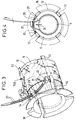
- each tube 11 On its rear part, each tube 11 has, as also shown in FIGS. 3 and 4, a set of slots 14 assigned to the passage of the belts from the interior surface to the exterior surface of the tube. It also has a rear end shoulder 15 for rear traction of the tube, according to arrow 16 for the tubular part 10B and in the opposite direction for the other part 10A.
- This shoulder can of course be replaced by another means facilitating the rear traction of the tube, for example by insertion holes of a traction tool in the rear part of said tube.
- One of the tubes 11, or preferably each of the two tubes thus rendered of identical embodiment, also has two through passages 20, provided side by side in the rear part of the tube concerned. These two passages of only one of the two tubes are assigned to the reception of a means of locking in translation 21 of this tube 11 or of the only tubular part concerned 10A, while the other tubular part 10B is released from below. of the sleeve.
- This locking means 21 maintains the tubular part 10A in position on the corresponding cable 4, that is to say relative to the element 3.
- the locking means is in particular a clamping strap, mounted through the two passages in the tube, forming a loop surrounding the cable 4. It is closed on itself on the outside of the tubular part 10A. To this end, it has a closure ring 22 on one of its end parts, to receive the other end part.
- the latter advantageously has grooves 23 to prevent it from sliding in the ring when the strap is tight to apply and hold the cable 4 against the tubular part 10A, as symbolized by the arrow 24 in FIGS. 1 and 4 and illustrated in the figure 2.
- the sleeve 2 has been shown partially in place with clamping, by releasing the tubular part 10B according to arrow 16 below the sleeve.
- the tubular part 10A remains firmly held in position relative to the element 3 throughout the release operation of the part 10B.
- the strap is opened or cut to release the tubular part 10A relative to the cable 4 and therefore to the element 4.
- the tubular parts being released from below the sleeve, they are removed from the top of the cables 4. They have for this purpose, as well known, a longitudinal line of initiation of rupture on the tube.
- the film located against the inner surface of the tube when the latter is released from the underside of the sleeve, can easily be brought back onto the outside of the tube, by hand-driving the belts 13, to be cut before rupture of the tube 11.
- This spiral support 1 ′ is constituted by successive turns integral in length with one another and capable of undoing one after the other by traction on the terminal turn called before 10′B and the following from the rear end of the support.
- An additional length 30 is integral with the front coil 10'A and is made accessible on the rear end of the support for this traction.
- This support 1 ' is equipped similarly to the previous support 1, for locking in translation of its rear part while the front and following turns are undone and released from below the sleeve.
- This spiral support 1 ′ can also have a rupture generating line, not shown, and be formed of turns or annular rings integral with each other along the rupture line, to be undone by alternating unwinding in one direction and the 'other.
- the support for laying the retractable sleeve can be constituted by two spiral tubes mounted end to end to carry the sleeve. Under these conditions, one of the last turns to be released from below the sleeve, which belongs to one and the other of these two spiral tubes is temporarily blocked in translation during the release of the turns before each spiral tube concerned.
Applications Claiming Priority (2)
| Application Number | Priority Date | Filing Date | Title |
|---|---|---|---|
| FR9410971A FR2724444B1 (fr) | 1994-09-14 | 1994-09-14 | Support de pose d'un manchon retractable |
| FR9410971 | 1994-09-14 |
Publications (2)
| Publication Number | Publication Date |
|---|---|
| EP0702444A1 true EP0702444A1 (de) | 1996-03-20 |
| EP0702444B1 EP0702444B1 (de) | 1998-11-11 |
Family
ID=9466932
Family Applications (1)
| Application Number | Title | Priority Date | Filing Date |
|---|---|---|---|
| EP95402047A Expired - Lifetime EP0702444B1 (de) | 1994-09-14 | 1995-09-11 | Verlegungsstütze für eine rückstellfähige Manschette |
Country Status (6)
| Country | Link |
|---|---|
| US (1) | US5577310A (de) |
| EP (1) | EP0702444B1 (de) |
| CA (1) | CA2158244C (de) |
| DE (1) | DE69505929T2 (de) |
| ES (1) | ES2126850T3 (de) |
| FR (1) | FR2724444B1 (de) |
Cited By (6)
| Publication number | Priority date | Publication date | Assignee | Title |
|---|---|---|---|---|
| US6103975A (en) * | 1998-06-29 | 2000-08-15 | 3M Innovative Properties Company | Pre-assembled electrical splice component |
| EP1852949A1 (de) | 2006-05-05 | 2007-11-07 | 3M Innovative Properties Company | Rohrförmiger Kabelanschluß |
| WO2007130811A2 (en) | 2006-05-05 | 2007-11-15 | 3M Innovative Properties Company | Tubular terminal for a cable |
| EP2608338A1 (de) | 2011-12-21 | 2013-06-26 | 3M Innovative Properties Company | Endgerätverbindungsvorrichtung für ein Stromkabel |
| EP3112238A1 (de) * | 2015-07-02 | 2017-01-04 | Canyon Bicycles GmbH | Leitungs-fixierelement für in fahrradrahmenrohren angeordnete leitungen, fahrradrahmenrohr sowie verfahren zur anordnung und fixierung einer leitung in einem fahrradrahmenrohr |
| EP3764492A1 (de) * | 2019-07-11 | 2021-01-13 | Nexans | Verfahren zur herstellung eines verbindungsanschlusses zwischen den abschirmungen von zwei elektrischen kabeln, und entsprechender anschluss |
Families Citing this family (15)
| Publication number | Priority date | Publication date | Assignee | Title |
|---|---|---|---|---|
| FR2746459B1 (fr) * | 1996-03-21 | 1998-04-24 | Alcatel Cable | Procede et ensemble de depose a serrage d'un revetement tubulaire elastique sur un element |
| FR2761830B1 (fr) * | 1997-04-07 | 2000-01-28 | Pirelli Cables Sa | Support de jonction a extraction autonome commandee |
| US5992010A (en) * | 1997-11-03 | 1999-11-30 | Zamanzadeh; Manouchehr | Coaxial cable connector tool |
| EP0917269B1 (de) * | 1997-11-15 | 2001-01-17 | NKT Cables GmbH | Stützkörper für einen hohlen Körper |
| US6276042B1 (en) * | 1999-02-12 | 2001-08-21 | Jim Hammond | Drive belt quick change tool and method |
| US20040262025A1 (en) * | 2001-09-21 | 2004-12-30 | Konrad Brandt | Multi-part insulating cover |
| US8119193B2 (en) * | 2004-10-27 | 2012-02-21 | Prysmian Cavi E Sistemi Energia S.R.L. | Method and device for coating the junction area between at least two elongated elements, in particular between electric cables |
| AU2005337582B2 (en) | 2005-10-19 | 2011-02-03 | Prysmian Cavi E Sistemi Energia S.R.L. | Method and apparatus for joining a pair of electric cables |
| RU2493643C2 (ru) | 2009-02-05 | 2013-09-20 | Зм Инновейтив Пропертиз Компани | Сборка для сращивания электрических кабелей с экранирующей оплеткой |
| US8853563B2 (en) | 2010-04-16 | 2014-10-07 | Thomas & Betts International, Llc | Cold shrink assembly |
| US9202612B2 (en) | 2012-09-28 | 2015-12-01 | Thomas & Betts International, Llc | Cold shrink assembly |
| US9190815B2 (en) * | 2013-01-31 | 2015-11-17 | Tyco Electronics Corporation | Method for installing cover sleeves on electrical connections |
| EP3014721A4 (de) | 2013-06-26 | 2017-02-15 | 3M Innovative Properties Company | Stromkabelklemmenverbindungsvorrichtung |
| CN108890263B (zh) * | 2018-08-22 | 2024-02-23 | 江苏众信绿色管业科技有限公司 | 一种钢衬复合管的组装设备 |
| CA3136371A1 (en) | 2019-04-09 | 2020-10-15 | 3M Innovative Properties Company | Support core for an elastic sleeve |
Citations (8)
| Publication number | Priority date | Publication date | Assignee | Title |
|---|---|---|---|---|
| US3384700A (en) * | 1966-04-19 | 1968-05-21 | Christopher W. Mier | Splice insulating device of the heavy duty type |
| US3515798A (en) | 1968-12-06 | 1970-06-02 | Minnesota Mining & Mfg | Elastic cover and removable cone assembly |
| US3823254A (en) | 1973-06-18 | 1974-07-09 | Roart Plastics Inc | Cable splice housing |
| FR2505567A1 (fr) * | 1981-05-07 | 1982-11-12 | Silec Liaisons Elec | Element de gousset de protection et d'isolation pour raccord de cables electriques |
| FR2592825A1 (fr) * | 1986-01-13 | 1987-07-17 | Artema | Manchon auxiliaire de positionnement, dispositif dote d'un tel manchon et procede de positionnement correspondant |
| EP0424090A2 (de) * | 1989-10-16 | 1991-04-24 | Minnesota Mining And Manufacturing Company | Abdeckung aus Elastomer mit anschmiegsamem Inneren |
| EP0541000A1 (de) | 1991-11-08 | 1993-05-12 | PIRELLI CAVI S.p.A. | Montage einer Umhüllung auf gestreckte zylindrische Gegenstände, so zum Beispiel auf elektrische Kabelspleisse |
| WO1993022816A1 (en) | 1992-04-28 | 1993-11-11 | Minnesota Mining And Manufacturing Company | Removable core for pre-streched tube |
Family Cites Families (6)
| Publication number | Priority date | Publication date | Assignee | Title |
|---|---|---|---|---|
| US3808352A (en) * | 1972-10-26 | 1974-04-30 | Minnesota Mining & Mfg | Elastomeric terminal insulator and stress cone and conductor terminated therewith |
| US3946480A (en) * | 1975-04-11 | 1976-03-30 | Communications Technology Corporation | Apparatus for use in applying an expandable resilient sleeve to a member therein |
| US4140412A (en) * | 1977-07-06 | 1979-02-20 | Vitt Louis O | Method of covering a joint of two rope ends |
| US4164621A (en) * | 1977-08-08 | 1979-08-14 | Amerace Corporation | Cable shield connecting device |
| US4506430A (en) * | 1983-09-19 | 1985-03-26 | Panduit Corp. | Elastic cover applicator and method of applying cover |
| DE3715915A1 (de) * | 1987-05-13 | 1988-12-08 | Minnesota Mining & Mfg | Stuetzwendel fuer einen radial gedehnten huelsenkoerper |
-
1994
- 1994-09-14 FR FR9410971A patent/FR2724444B1/fr not_active Expired - Fee Related
-
1995
- 1995-09-08 US US08/525,177 patent/US5577310A/en not_active Expired - Lifetime
- 1995-09-11 ES ES95402047T patent/ES2126850T3/es not_active Expired - Lifetime
- 1995-09-11 DE DE69505929T patent/DE69505929T2/de not_active Expired - Lifetime
- 1995-09-11 EP EP95402047A patent/EP0702444B1/de not_active Expired - Lifetime
- 1995-09-13 CA CA002158244A patent/CA2158244C/fr not_active Expired - Fee Related
Patent Citations (8)
| Publication number | Priority date | Publication date | Assignee | Title |
|---|---|---|---|---|
| US3384700A (en) * | 1966-04-19 | 1968-05-21 | Christopher W. Mier | Splice insulating device of the heavy duty type |
| US3515798A (en) | 1968-12-06 | 1970-06-02 | Minnesota Mining & Mfg | Elastic cover and removable cone assembly |
| US3823254A (en) | 1973-06-18 | 1974-07-09 | Roart Plastics Inc | Cable splice housing |
| FR2505567A1 (fr) * | 1981-05-07 | 1982-11-12 | Silec Liaisons Elec | Element de gousset de protection et d'isolation pour raccord de cables electriques |
| FR2592825A1 (fr) * | 1986-01-13 | 1987-07-17 | Artema | Manchon auxiliaire de positionnement, dispositif dote d'un tel manchon et procede de positionnement correspondant |
| EP0424090A2 (de) * | 1989-10-16 | 1991-04-24 | Minnesota Mining And Manufacturing Company | Abdeckung aus Elastomer mit anschmiegsamem Inneren |
| EP0541000A1 (de) | 1991-11-08 | 1993-05-12 | PIRELLI CAVI S.p.A. | Montage einer Umhüllung auf gestreckte zylindrische Gegenstände, so zum Beispiel auf elektrische Kabelspleisse |
| WO1993022816A1 (en) | 1992-04-28 | 1993-11-11 | Minnesota Mining And Manufacturing Company | Removable core for pre-streched tube |
Cited By (10)
| Publication number | Priority date | Publication date | Assignee | Title |
|---|---|---|---|---|
| US6103975A (en) * | 1998-06-29 | 2000-08-15 | 3M Innovative Properties Company | Pre-assembled electrical splice component |
| EP1852949A1 (de) | 2006-05-05 | 2007-11-07 | 3M Innovative Properties Company | Rohrförmiger Kabelanschluß |
| WO2007130811A2 (en) | 2006-05-05 | 2007-11-15 | 3M Innovative Properties Company | Tubular terminal for a cable |
| EP2608338A1 (de) | 2011-12-21 | 2013-06-26 | 3M Innovative Properties Company | Endgerätverbindungsvorrichtung für ein Stromkabel |
| WO2013096354A1 (en) | 2011-12-21 | 2013-06-27 | 3M Innovative Properties Company | Terminal connection device for a power cable |
| EP2698891A1 (de) | 2011-12-21 | 2014-02-19 | 3M Innovative Properties Company | Endgerätverbindungsvorrichtung für ein Stromkabel |
| EP3112238A1 (de) * | 2015-07-02 | 2017-01-04 | Canyon Bicycles GmbH | Leitungs-fixierelement für in fahrradrahmenrohren angeordnete leitungen, fahrradrahmenrohr sowie verfahren zur anordnung und fixierung einer leitung in einem fahrradrahmenrohr |
| US10723407B2 (en) | 2015-07-02 | 2020-07-28 | Canyon Bicycles Gmbh | Line fixing element for lines arranged in bicycle frame tubes, bicycle frame tubes, as well as method for arranging and fixing a line in a bicycle frame tube |
| EP3764492A1 (de) * | 2019-07-11 | 2021-01-13 | Nexans | Verfahren zur herstellung eines verbindungsanschlusses zwischen den abschirmungen von zwei elektrischen kabeln, und entsprechender anschluss |
| FR3098634A1 (fr) * | 2019-07-11 | 2021-01-15 | Nexans | Procede de fabrication d’une jonction entre les ecrans de deux cables electriques et jonction correspondante |
Also Published As
| Publication number | Publication date |
|---|---|
| DE69505929D1 (de) | 1998-12-17 |
| CA2158244C (fr) | 2000-04-04 |
| ES2126850T3 (es) | 1999-04-01 |
| DE69505929T2 (de) | 1999-04-08 |
| US5577310A (en) | 1996-11-26 |
| EP0702444B1 (de) | 1998-11-11 |
| FR2724444A1 (fr) | 1996-03-15 |
| FR2724444B1 (fr) | 1996-11-22 |
| CA2158244A1 (fr) | 1996-03-15 |
Similar Documents
| Publication | Publication Date | Title |
|---|---|---|
| EP0702444B1 (de) | Verlegungsstütze für eine rückstellfähige Manschette | |
| EP0631357B1 (de) | Rohrförmiger Träger zum Montieren einer elastischen schrumpfbaren Hülse | |
| WO1998045918A1 (fr) | Dispositif de jonction de cable electrique | |
| FR2537221A1 (fr) | Collier de serrage | |
| FR2762455A1 (fr) | Piece de raccordement etanche d'un tube a l'orifice d'une paroi | |
| FR2926410A1 (fr) | Ensemble pour recouvrir a enserrement un element allonge avec un manchon elastique de protection | |
| WO2003054438A1 (fr) | Gaine de protection refermable par recouvrement et utilisation de cette gaine | |
| EP0619636B1 (de) | Vorrichtung zum Tragen einer elastischen Muffe und durch eine entfernbare Tragvorrichtung in ausgedehntem Zustand gehaltene elastische Muffe | |
| FR2477204A1 (fr) | Mecanisme pour mat telescopique | |
| EP1342458A1 (de) | Magenband mit balgförmigem Ballon | |
| FR3017178A1 (fr) | Gaine tubulaire annelee comportant un moyen de serrage interieur | |
| EP1198684B1 (de) | Schutzkappe für ein rohrende | |
| EP0797281B1 (de) | Verfahren und Vorrichtung zum Aufbringen einer elastischen rohrförmigen Umhüllung unter Klemmwirkung auf ein Element | |
| EP1263107B1 (de) | Vorrichtung zum Halten einer elastischen Muffe in aufgeweitetem Zustand | |
| CA2652684C (fr) | Ensemble pour recouvrir a enserrement un element allonge avec un manchon elastique de protection | |
| EP2552270A1 (de) | Vorrichtung zum verschliessen und befestigen zweier längen einer biegsamen umreifung | |
| EP0963022B1 (de) | Verfahren und Vorrichtung zum Aufbringen eines rohrförmigen Elements auf ein Aufnahmeteil und daraus resultierende Anordnung | |
| FR2623474A1 (fr) | Perfectionnement au dispositif pour le conditionnement de gaines tubulaires souples | |
| FR2685141A1 (fr) | Jonction de cables electriques, ensemble premonte de jonction et procede de mise en óoeuvre. | |
| EP3540888B1 (de) | Einheit zur ummantelung eines länglichen elements mit einer elastischen schutzhülle | |
| EP1084529B1 (de) | Vorrichtung zum verbinden eines drahtes oder kabels zwecks ziehens sowie verfahren zu dessen anbringung | |
| FR2692406A1 (fr) | Dispositif de guidage et de protection de conducteurs électriques. | |
| FR2651651A1 (fr) | Procede de montage d'un element de prehension d'un bagage et bagage comprenant un tel element. | |
| EP0860925B1 (de) | Kaltschrumpfbare geschlitzte Vorrichtung zum Abdichten und Schützen | |
| FR2547247A1 (fr) | Dispositif de guidage pour la mise en place d'une roue sur l'essieu d'un vehicule automobile |
Legal Events
| Date | Code | Title | Description |
|---|---|---|---|
| PUAI | Public reference made under article 153(3) epc to a published international application that has entered the european phase |
Free format text: ORIGINAL CODE: 0009012 |
|
| AK | Designated contracting states |
Kind code of ref document: A1 Designated state(s): BE DE ES GB IT SE |
|
| 17P | Request for examination filed |
Effective date: 19960629 |
|
| 17Q | First examination report despatched |
Effective date: 19970224 |
|
| GRAG | Despatch of communication of intention to grant |
Free format text: ORIGINAL CODE: EPIDOS AGRA |
|
| GRAG | Despatch of communication of intention to grant |
Free format text: ORIGINAL CODE: EPIDOS AGRA |
|
| GRAH | Despatch of communication of intention to grant a patent |
Free format text: ORIGINAL CODE: EPIDOS IGRA |
|
| GRAH | Despatch of communication of intention to grant a patent |
Free format text: ORIGINAL CODE: EPIDOS IGRA |
|
| RAP1 | Party data changed (applicant data changed or rights of an application transferred) |
Owner name: ALCATEL ALSTHOM COMPAGNIE GENERALE D'ELECTRICITE |
|
| GRAA | (expected) grant |
Free format text: ORIGINAL CODE: 0009210 |
|
| AK | Designated contracting states |
Kind code of ref document: B1 Designated state(s): BE DE ES GB IT SE |
|
| REF | Corresponds to: |
Ref document number: 69505929 Country of ref document: DE Date of ref document: 19981217 |
|
| GBT | Gb: translation of ep patent filed (gb section 77(6)(a)/1977) |
Effective date: 19990128 |
|
| RAP4 | Party data changed (patent owner data changed or rights of a patent transferred) |
Owner name: ALCATEL |
|
| RAP4 | Party data changed (patent owner data changed or rights of a patent transferred) |
Owner name: ALCATEL |
|
| REG | Reference to a national code |
Ref country code: ES Ref legal event code: FG2A Ref document number: 2126850 Country of ref document: ES Kind code of ref document: T3 |
|
| PLBE | No opposition filed within time limit |
Free format text: ORIGINAL CODE: 0009261 |
|
| STAA | Information on the status of an ep patent application or granted ep patent |
Free format text: STATUS: NO OPPOSITION FILED WITHIN TIME LIMIT |
|
| 26N | No opposition filed | ||
| PGFP | Annual fee paid to national office [announced via postgrant information from national office to epo] |
Ref country code: SE Payment date: 20000825 Year of fee payment: 6 |
|
| PG25 | Lapsed in a contracting state [announced via postgrant information from national office to epo] |
Ref country code: SE Free format text: LAPSE BECAUSE OF NON-PAYMENT OF DUE FEES Effective date: 20010912 |
|
| REG | Reference to a national code |
Ref country code: GB Ref legal event code: 732E |
|
| BECH | Be: change of holder |
Free format text: 20010727 *NEXANS |
|
| REG | Reference to a national code |
Ref country code: GB Ref legal event code: IF02 |
|
| EUG | Se: european patent has lapsed |
Ref document number: 95402047.5 |
|
| PGFP | Annual fee paid to national office [announced via postgrant information from national office to epo] |
Ref country code: BE Payment date: 20081001 Year of fee payment: 14 |
|
| BERE | Be: lapsed |
Owner name: *NEXANS Effective date: 20090930 |
|
| PG25 | Lapsed in a contracting state [announced via postgrant information from national office to epo] |
Ref country code: BE Free format text: LAPSE BECAUSE OF NON-PAYMENT OF DUE FEES Effective date: 20090930 |
|
| PGFP | Annual fee paid to national office [announced via postgrant information from national office to epo] |
Ref country code: ES Payment date: 20100924 Year of fee payment: 16 |
|
| PGFP | Annual fee paid to national office [announced via postgrant information from national office to epo] |
Ref country code: GB Payment date: 20100921 Year of fee payment: 16 |
|
| PGFP | Annual fee paid to national office [announced via postgrant information from national office to epo] |
Ref country code: DE Payment date: 20100922 Year of fee payment: 16 |
|
| PGFP | Annual fee paid to national office [announced via postgrant information from national office to epo] |
Ref country code: IT Payment date: 20100927 Year of fee payment: 16 |
|
| GBPC | Gb: european patent ceased through non-payment of renewal fee |
Effective date: 20110911 |
|
| PG25 | Lapsed in a contracting state [announced via postgrant information from national office to epo] |
Ref country code: IT Free format text: LAPSE BECAUSE OF NON-PAYMENT OF DUE FEES Effective date: 20110911 |
|
| PG25 | Lapsed in a contracting state [announced via postgrant information from national office to epo] |
Ref country code: DE Free format text: LAPSE BECAUSE OF NON-PAYMENT OF DUE FEES Effective date: 20120403 |
|
| REG | Reference to a national code |
Ref country code: DE Ref legal event code: R119 Ref document number: 69505929 Country of ref document: DE Effective date: 20120403 |
|
| PG25 | Lapsed in a contracting state [announced via postgrant information from national office to epo] |
Ref country code: GB Free format text: LAPSE BECAUSE OF NON-PAYMENT OF DUE FEES Effective date: 20110911 |
|
| REG | Reference to a national code |
Ref country code: ES Ref legal event code: FD2A Effective date: 20130530 |
|
| PG25 | Lapsed in a contracting state [announced via postgrant information from national office to epo] |
Ref country code: ES Free format text: LAPSE BECAUSE OF NON-PAYMENT OF DUE FEES Effective date: 20110912 |