EP0702444A1 - Laying support for a recoverable sleeve - Google Patents
Laying support for a recoverable sleeve Download PDFInfo
- Publication number
- EP0702444A1 EP0702444A1 EP95402047A EP95402047A EP0702444A1 EP 0702444 A1 EP0702444 A1 EP 0702444A1 EP 95402047 A EP95402047 A EP 95402047A EP 95402047 A EP95402047 A EP 95402047A EP 0702444 A1 EP0702444 A1 EP 0702444A1
- Authority
- EP
- European Patent Office
- Prior art keywords
- sleeve
- tube
- tubular part
- released
- support
- Prior art date
- Legal status (The legal status is an assumption and is not a legal conclusion. Google has not performed a legal analysis and makes no representation as to the accuracy of the status listed.)
- Granted
Links
Images


Classifications
-
- H—ELECTRICITY
- H02—GENERATION; CONVERSION OR DISTRIBUTION OF ELECTRIC POWER
- H02G—INSTALLATION OF ELECTRIC CABLES OR LINES, OR OF COMBINED OPTICAL AND ELECTRIC CABLES OR LINES
- H02G15/00—Cable fittings
- H02G15/08—Cable junctions
- H02G15/18—Cable junctions protected by sleeves, e.g. for communication cable
- H02G15/182—Cable junctions protected by sleeves, e.g. for communication cable held in expanded condition in radial direction prior to installation
- H02G15/1826—Cable junctions protected by sleeves, e.g. for communication cable held in expanded condition in radial direction prior to installation on a removable hollow core, e.g. a tube
-
- H—ELECTRICITY
- H02—GENERATION; CONVERSION OR DISTRIBUTION OF ELECTRIC POWER
- H02G—INSTALLATION OF ELECTRIC CABLES OR LINES, OR OF COMBINED OPTICAL AND ELECTRIC CABLES OR LINES
- H02G1/00—Methods or apparatus specially adapted for installing, maintaining, repairing or dismantling electric cables or lines
- H02G1/14—Methods or apparatus specially adapted for installing, maintaining, repairing or dismantling electric cables or lines for joining or terminating cables
-
- Y—GENERAL TAGGING OF NEW TECHNOLOGICAL DEVELOPMENTS; GENERAL TAGGING OF CROSS-SECTIONAL TECHNOLOGIES SPANNING OVER SEVERAL SECTIONS OF THE IPC; TECHNICAL SUBJECTS COVERED BY FORMER USPC CROSS-REFERENCE ART COLLECTIONS [XRACs] AND DIGESTS
- Y10—TECHNICAL SUBJECTS COVERED BY FORMER USPC
- Y10T—TECHNICAL SUBJECTS COVERED BY FORMER US CLASSIFICATION
- Y10T29/00—Metal working
- Y10T29/49—Method of mechanical manufacture
- Y10T29/49002—Electrical device making
- Y10T29/49117—Conductor or circuit manufacturing
- Y10T29/49123—Co-axial cable
-
- Y—GENERAL TAGGING OF NEW TECHNOLOGICAL DEVELOPMENTS; GENERAL TAGGING OF CROSS-SECTIONAL TECHNOLOGIES SPANNING OVER SEVERAL SECTIONS OF THE IPC; TECHNICAL SUBJECTS COVERED BY FORMER USPC CROSS-REFERENCE ART COLLECTIONS [XRACs] AND DIGESTS
- Y10—TECHNICAL SUBJECTS COVERED BY FORMER USPC
- Y10T—TECHNICAL SUBJECTS COVERED BY FORMER US CLASSIFICATION
- Y10T29/00—Metal working
- Y10T29/49—Method of mechanical manufacture
- Y10T29/49002—Electrical device making
- Y10T29/49117—Conductor or circuit manufacturing
- Y10T29/49174—Assembling terminal to elongated conductor
- Y10T29/49176—Assembling terminal to elongated conductor with molding of electrically insulating material
- Y10T29/49178—Assembling terminal to elongated conductor with molding of electrically insulating material by shrinking of cover
-
- Y—GENERAL TAGGING OF NEW TECHNOLOGICAL DEVELOPMENTS; GENERAL TAGGING OF CROSS-SECTIONAL TECHNOLOGIES SPANNING OVER SEVERAL SECTIONS OF THE IPC; TECHNICAL SUBJECTS COVERED BY FORMER USPC CROSS-REFERENCE ART COLLECTIONS [XRACs] AND DIGESTS
- Y10—TECHNICAL SUBJECTS COVERED BY FORMER USPC
- Y10T—TECHNICAL SUBJECTS COVERED BY FORMER US CLASSIFICATION
- Y10T29/00—Metal working
- Y10T29/49—Method of mechanical manufacture
- Y10T29/49002—Electrical device making
- Y10T29/49117—Conductor or circuit manufacturing
- Y10T29/49194—Assembling elongated conductors, e.g., splicing, etc.
- Y10T29/49195—Assembling elongated conductors, e.g., splicing, etc. with end-to-end orienting
-
- Y—GENERAL TAGGING OF NEW TECHNOLOGICAL DEVELOPMENTS; GENERAL TAGGING OF CROSS-SECTIONAL TECHNOLOGIES SPANNING OVER SEVERAL SECTIONS OF THE IPC; TECHNICAL SUBJECTS COVERED BY FORMER USPC CROSS-REFERENCE ART COLLECTIONS [XRACs] AND DIGESTS
- Y10—TECHNICAL SUBJECTS COVERED BY FORMER USPC
- Y10T—TECHNICAL SUBJECTS COVERED BY FORMER US CLASSIFICATION
- Y10T29/00—Metal working
- Y10T29/53—Means to assemble or disassemble
- Y10T29/5313—Means to assemble electrical device
- Y10T29/532—Conductor
-
- Y—GENERAL TAGGING OF NEW TECHNOLOGICAL DEVELOPMENTS; GENERAL TAGGING OF CROSS-SECTIONAL TECHNOLOGIES SPANNING OVER SEVERAL SECTIONS OF THE IPC; TECHNICAL SUBJECTS COVERED BY FORMER USPC CROSS-REFERENCE ART COLLECTIONS [XRACs] AND DIGESTS
- Y10—TECHNICAL SUBJECTS COVERED BY FORMER USPC
- Y10T—TECHNICAL SUBJECTS COVERED BY FORMER US CLASSIFICATION
- Y10T29/00—Metal working
- Y10T29/53—Means to assemble or disassemble
- Y10T29/53657—Means to assemble or disassemble to apply or remove a resilient article [e.g., tube, sleeve, etc.]
Definitions
- the present invention relates to a sleeve for fitting a retractable sleeve, intended to ensure the fitting with tightening of the sleeve on an element to be covered.
- This type of support is as such known and used in particular for the installation of a sleeve on a cable terminal equipment or equipment for joining two cables or any element having to receive a sleeve retracting thereon.
- the support initially carries the expanded sleeve and is thus mounted on the element for positioning the sleeve on the latter. It is released for the direct installation and simultaneous retraction of the sleeve on the element.
- Document FR-A 2592825 describes an embodiment of such a support, constituted by a tube which is released from below the expanded sleeve, for the positioning of the sleeve on an internal element.
- a sliding film covers the outside surface of the tube over at least part of its length. The film is fixed to one of the so-called front ends of the tube, is moreover free on the external surface of the tube and is thus trapped between the expanded sleeve and the tube. The tube is released by pulling it by its so-called rear end, advantageously not covered by the film.
- the sleeve As the tube is released, the sleeve is put in place and retracts simultaneously on the element, with the film turning on itself between the sleeve and the element. When the tube is completely released from below the sleeve, the film is in turn released by an additional stroke of the tube.
- Such a support is in practice used when the sleeve is relatively short and / or of relatively small thickness.
- a double support is used, the two parts of which consist of two tubes, such as the aforementioned tube, which are independent of one another and arranged head to tail. end to end and carry the expanded sleeve. The two parts are released one after the other from below the sleeve, when the latter is put in place.
- This spiral tube is released from the expanded sleeve by pulling on the so-called front end winding and the following turns, from the opposite so-called rear end of the tube, to undo the tube.
- a tab linked to the front end turn extends for this purpose from the inside of the tube to beyond the rear end of this tube.
- spiral supports pose the same problem as the double supports and tend to move on the element, when they are undone to disengage them from the underside of the sleeve then placed incorrectly in place.
- the object of the present invention is to remedy this problem and thus allow the correct fitting of the retractable sleeve.
- a support for laying a retractable sleeve intended to carry the expanded sleeve, to position the sleeve on an element and to ensure the fitting with tightening of the sleeve on said element by releasing the support from below said sleeve , comprising tubular parts substantially contiguous and released in turn from the underside of said sleeve, characterized in that it further comprises a temporary blocking means of the last tubular part to be released from the underside of said sleeve, for the fixed positioning of said last tubular part relatively to said element during the release of each other tubular part.
- FIGs 1, 2 and 5 there is illustrated a support 1 or 1 'equipped according to the invention for the installation of an elastically retractable sleeve 2 on an element 3 for joining two cables 4, this element being visible in the Figures 1, 2 and 5 alone.
- the junction element connects the stripped cores 5 of the two cables, the terminal parts of the cables being previously prepared by degraded removal of the outer sheath 6, of the conductive screen and / or semiconductor 7 and internal insulation 8 surrounding the core of each cable.
- the sleeve 2 belongs as such to the junction and must partially cover the stripped screen of each cable and extend between the screens. Alternatively, it can provide external protection for the junction and then extends over the end portions of the cable sheaths and between them. Alternatively also, it may belong to the junction, constituting the junction body and ensuring both the external protection of the junction.
- This sleeve as such outside of the present invention has therefore been illustrated as a single layer. It is in practice multilayer or monolayer and / or formed of a double sleeve, depending on the functions performed.
- the support 1 is constituted by two tubular parts 10A and 10B, similar to each other and arranged end to end by one of their ends called front. It carries the expanded sleeve, which extends over the two tubular parts, to the positioning of the sleeve and its fitting with clamping on the element 3 and the stripped parts of the two cables. It is of sufficient internal dimensions to slide on the cables, for its positioning with the sleeve on the element 3 and the release of its tubular parts from below the sleeve with the resulting positioning of the sleeve simultaneously.
- Each tubular part identically comprises, as referenced on the single part 10A, a rigid tube 11, preferably made of plastic, and a flexible and resistant film 12 having a low coefficient of friction.
- This film covers the outer surface of the tube and extends from its front end to substantially its opposite rear end. Preferably this film is free on the tube 11 and does not cover the rear end of the tube.
- the tube then further carries a means 13 for driving the film 12, from its outer surface, around its front end and on its inner surface, when this tubular part is released by rear traction from the underside of the sleeve.
- This drive means is in this example a set of belts integral with the front edge and the rear edge of the film and connecting them to each other.
- the belts extend inside the tube and on the rear outer part of the tube.
- these belts extend externally and internally on the tube, each forming a closed loop on itself for driving the film between each belt and the tube.
- the film and the belts are analogous in nature. They preferably have a surface film coating which is non-stick, for example silicone-based.
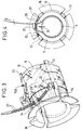
- each tube 11 On its rear part, each tube 11 has, as also shown in FIGS. 3 and 4, a set of slots 14 assigned to the passage of the belts from the interior surface to the exterior surface of the tube. It also has a rear end shoulder 15 for rear traction of the tube, according to arrow 16 for the tubular part 10B and in the opposite direction for the other part 10A.
- This shoulder can of course be replaced by another means facilitating the rear traction of the tube, for example by insertion holes of a traction tool in the rear part of said tube.
- One of the tubes 11, or preferably each of the two tubes thus rendered of identical embodiment, also has two through passages 20, provided side by side in the rear part of the tube concerned. These two passages of only one of the two tubes are assigned to the reception of a means of locking in translation 21 of this tube 11 or of the only tubular part concerned 10A, while the other tubular part 10B is released from below. of the sleeve.
- This locking means 21 maintains the tubular part 10A in position on the corresponding cable 4, that is to say relative to the element 3.
- the locking means is in particular a clamping strap, mounted through the two passages in the tube, forming a loop surrounding the cable 4. It is closed on itself on the outside of the tubular part 10A. To this end, it has a closure ring 22 on one of its end parts, to receive the other end part.
- the latter advantageously has grooves 23 to prevent it from sliding in the ring when the strap is tight to apply and hold the cable 4 against the tubular part 10A, as symbolized by the arrow 24 in FIGS. 1 and 4 and illustrated in the figure 2.
- the sleeve 2 has been shown partially in place with clamping, by releasing the tubular part 10B according to arrow 16 below the sleeve.
- the tubular part 10A remains firmly held in position relative to the element 3 throughout the release operation of the part 10B.
- the strap is opened or cut to release the tubular part 10A relative to the cable 4 and therefore to the element 4.
- the tubular parts being released from below the sleeve, they are removed from the top of the cables 4. They have for this purpose, as well known, a longitudinal line of initiation of rupture on the tube.
- the film located against the inner surface of the tube when the latter is released from the underside of the sleeve, can easily be brought back onto the outside of the tube, by hand-driving the belts 13, to be cut before rupture of the tube 11.
- This spiral support 1 ′ is constituted by successive turns integral in length with one another and capable of undoing one after the other by traction on the terminal turn called before 10′B and the following from the rear end of the support.
- An additional length 30 is integral with the front coil 10'A and is made accessible on the rear end of the support for this traction.
- This support 1 ' is equipped similarly to the previous support 1, for locking in translation of its rear part while the front and following turns are undone and released from below the sleeve.
- This spiral support 1 ′ can also have a rupture generating line, not shown, and be formed of turns or annular rings integral with each other along the rupture line, to be undone by alternating unwinding in one direction and the 'other.
- the support for laying the retractable sleeve can be constituted by two spiral tubes mounted end to end to carry the sleeve. Under these conditions, one of the last turns to be released from below the sleeve, which belongs to one and the other of these two spiral tubes is temporarily blocked in translation during the release of the turns before each spiral tube concerned.
Abstract
Description
La présente invention porte sur un manchon de pose d'un manchon rétractable, destiné à assurer la mise en place avec serrage du manchon sur un élément à recouvrir.The present invention relates to a sleeve for fitting a retractable sleeve, intended to ensure the fitting with tightening of the sleeve on an element to be covered.
Ce type de support est en tant que tel connu et utilisé notament pour la mise en place d'un manchon sur un équipement terminal de câble ou un équipement de jonction de deux câbles ou tout élément devant recevoir un manchon se rétractant sur celui-ci. Le support porte initialement le manchon expansé et est ainsi monté sur l'élément pour le positionnement du manchon sur ce dernier. Il est dégagé pour la mise en place directement et la rétraction simultanément du manchon sur l'élément.This type of support is as such known and used in particular for the installation of a sleeve on a cable terminal equipment or equipment for joining two cables or any element having to receive a sleeve retracting thereon. The support initially carries the expanded sleeve and is thus mounted on the element for positioning the sleeve on the latter. It is released for the direct installation and simultaneous retraction of the sleeve on the element.
Le document FR-A 2592825 décrit un mode de réalisation d'un tel support, constitué par un tube qui est dégagé du dessous du manchon expansé, pour la mise en place du manchon sur un élément intérieur. Selon ce document, un film de glissement recouvre la surface extérieure du tube sur au moins une partie de sa longueur. Le film est fixé à l'une des extrémités dite avant du tube, est par ailleurs libre sur la surface extérieure du tube et est ainsi prisonnier entre le manchon expansé et le tube. Le dégagement du tube est effectué en le tirant par son extrémité dite arrière, avantageusement non recouverte par le film.Document FR-A 2592825 describes an embodiment of such a support, constituted by a tube which is released from below the expanded sleeve, for the positioning of the sleeve on an internal element. According to this document, a sliding film covers the outside surface of the tube over at least part of its length. The film is fixed to one of the so-called front ends of the tube, is moreover free on the external surface of the tube and is thus trapped between the expanded sleeve and the tube. The tube is released by pulling it by its so-called rear end, advantageously not covered by the film.
Au fur et à mesure du dégagement du tube, le manchon se met en place et se rétracte simultanément sur l'élément, avec le film se retournant sur lui-même entre le manchon et l'élément. Quand le tube est totalement dégagé du dessous du manchon, le film est à son tour dégagé par une course supplémentaire du tube.As the tube is released, the sleeve is put in place and retracts simultaneously on the element, with the film turning on itself between the sleeve and the element. When the tube is completely released from below the sleeve, the film is in turn released by an additional stroke of the tube.
Un tel support est en pratique utilisé lorsque le manchon est relativement court et/ou d'épaisseur relativement faible. Lorsque la manchon est long et/ou épais, on utilise un support double, dont les deux parties sont constituées par deux tubes, tels que le tube précité, qui sont indépendants l'un de l'autre et disposés tête-bêche bout à bout et portent le manchon expansé. Les deux parties sont dégagées l'une après l'autre du dessous du manchon, lors de la mise en place de ce dernier.Such a support is in practice used when the sleeve is relatively short and / or of relatively small thickness. When the sleeve is long and / or thick, a double support is used, the two parts of which consist of two tubes, such as the aforementioned tube, which are independent of one another and arranged head to tail. end to end and carry the expanded sleeve. The two parts are released one after the other from below the sleeve, when the latter is put in place.
Le problème posé par un tel support double tube est que lors du dégagement du premier des deux tubes, le deuxième tube a tendance à se déplacer avec le premier sur l'élément. Ceci conduit à un mauvais positionnement du manchon sur l'élément.The problem with such a double tube support is that when the first of the two tubes is released, the second tube tends to move with the first on the element. This leads to improper positioning of the sleeve on the element.
Le document US-A-3 515 798 décrit un autre mode de réalisation d'un tel support dit tube spiralé. Ce tube spiralé est à spires hélicoïdales, continues et liées sur leur longueur les unes aux autres, qui définissent autant de parties tubulaires élémentaires solidaires les unes des autres que de spires sur le tube spiralé unique.Document US-A-3 515 798 describes another embodiment of such a support called a spiral tube. This spiral tube has helical turns, continuous and linked along their length to each other, which define as many elementary tubular parts integral with each other as turns on the single spiral tube.
Ce tube spiralé est dégagé du manchon expansé en tirant sur la spire terminale dite avant et les spires suivantes, depuis l'extrémité opposée dite arrière du tube, pour défaire le tube. Une patte liée à la spire terminale avant s'étend à cet effet par l'intérieur du tube jusqu'au delà de l'extrémité arrière de ce tube.This spiral tube is released from the expanded sleeve by pulling on the so-called front end winding and the following turns, from the opposite so-called rear end of the tube, to undo the tube. A tab linked to the front end turn extends for this purpose from the inside of the tube to beyond the rear end of this tube.
Le document WO 93/22816 décrit également un support dit tube spiralé dont les spires sont annulaires et définissent entre elles un serpentin pour défaire les spires alternativement dans un sens et l'autre.Document WO 93/22816 also describes a support known as a spiral tube, the turns of which are annular and define between them a serpentine to defeat the turns alternately in one direction and the other.
Ces supports spiralés posent le même problème que les supports doubles et ont tendance à se déplacer sur l'élément, quand on les défait pour les dégager du dessous du manchon alors mis incorrectement en place.These spiral supports pose the same problem as the double supports and tend to move on the element, when they are undone to disengage them from the underside of the sleeve then placed incorrectly in place.
La présente invention a pour but de remédier à ce problème et ainsi de permettre la mise en place correcte du manchon rétractable.The object of the present invention is to remedy this problem and thus allow the correct fitting of the retractable sleeve.
Elle a pour objet un support de pose d'un manchon rétractable, destiné à porter le manchon expansé, à positionner le manchon sur un élément et à assurer la mise en place avec serrage du manchon sur ledit élément par dégagement du support du dessous dudit manchon, comportant des parties tubulaires sensiblement jointives et dégagées tour à tour du dessous dudit manchon, caractérisé en ce qu'il comporte en outre un moyen de blocage temporaire de la dernière partie tubulaire à dégager du dessous dudit manchon, pour le positionnement fixe de ladite dernière partie tubulaire relativement audit élément pendant le dégagement de chaque autre partie tubulaire .It relates to a support for laying a retractable sleeve, intended to carry the expanded sleeve, to position the sleeve on an element and to ensure the fitting with tightening of the sleeve on said element by releasing the support from below said sleeve , comprising tubular parts substantially contiguous and released in turn from the underside of said sleeve, characterized in that it further comprises a temporary blocking means of the last tubular part to be released from the underside of said sleeve, for the fixed positioning of said last tubular part relatively to said element during the release of each other tubular part.
Ce support présente avantageusement en outre au moins l'une des caractéristiques additionnelles suivantes :
- le moyen de blocage est un moyen de serrage, en particulier une lanière, traversant ladite dernière partie tubulaire et formant une boucle intérieure, fermée sur elle-même sur l'extérieur de ladite dernière partie tubulaire, pour laquelle sont prévus deux passages traversants dans ladite dernière partie tubulaire.
- le support comporte deux tubes qui sont montés bout à bout par leurs extrémités dites avant et constituent lesdites parties tubulaires, et ledit moyen de blocage est monté sur la partie terminale opposée à l'extrémité avant du tube dégagé en dernier, qui constitue ladite dernière partie tubulaire.
- le support est formé par un tube spiralé unique, dont les spires, constituent lesdites parties tubulaires, alors élémentaires, à dégager successivement du dessous dudit manchon depuis l'une des deux spires terminales dite spire avant et ledit moyen de blocage est monté à travers l'une des spires sensiblement opposées à la spire avant et dites arrière, ces spires arrière constituant ladite dernière partie tubulaire dégagée.
- the locking means is a clamping means, in particular a strap, passing through said last tubular part and forming an inner loop, closed on itself on the outside of said last tubular part, for which two through passages are provided in said last tubular part.
- the support comprises two tubes which are mounted end to end by their so-called front ends and constitute said tubular parts, and said blocking means is mounted on the end part opposite to the front end of the tube released last, which constitutes said last part tubular.
- the support is formed by a single spiral tube, the turns of which constitute said tubular parts, then elementary, to be released successively from below said sleeve from one of the two terminal turns called the front turn and said blocking means is mounted through the 'one of the turns substantially opposite to the front turn and said rear, these rear turns constituting said last tubular part released.
Les caractéristiques et avantages de la présente invention ressortiront de la description faite ci-après d'exemples de réalisation illustrés dans les dessins ci-annexés. Dans ces dessins :
- la figure 1 est une vue schématique en coupe d'un support de pose d'un manchon rétractable, selon l'invention,
- la figure 2 est une vue schématique partielle du support selon la figure 1, illustrant l'opération de pose du manchon,
- les figures 3 et 4 sont deux vues en perspective partielle et latérale du support de la figure 1,
- la figure 5 est une vue schématique en perspective d'une variante de réalisation du support équipé selon l'invention.
- FIG. 1 is a schematic sectional view of a support for laying a retractable sleeve, according to the invention,
- FIG. 2 is a partial schematic view of the support according to FIG. 1, illustrating the operation of fitting the sleeve,
- FIGS. 3 and 4 are two partial and lateral perspective views of the support of FIG. 1,
- Figure 5 is a schematic perspective view of an alternative embodiment of the support equipped according to the invention.
Dans les figures 1, 2 et 5, on a illustré un support 1 ou 1' équipé selon l'invention pour la pose d'un manchon élastiquement rétractable 2 sur un élément 3 de jonction de deux câbles 4, cet élément étant visible dans les seules figures 1, 2 et 5. Dans ces exemples l'élément de jonction raccorde les âmes dénudées 5 des deux câbles, les parties terminales des câbles étant préalablement préparées par retrait en dégradé de la gaine extérieure 6, de l'écran conducteur et/ou semiconducteur 7 et de l'isolation interne 8 entourant l'âme de chaque câble.In Figures 1, 2 and 5, there is illustrated a support 1 or 1 'equipped according to the invention for the installation of an elastically
Dans ces exemples le manchon 2 appartient en tant que tel à la jonction et doit venir recouvrir partiellement l'écran dénudé de chaque câble et s'étendre entre les écrans. En variante, il peut assurer la protection extérieure de la jonction et s'étend alors sur les parties terminales des gaines des câbles et entre elles. En variante également, il peut appartenir à la jonction, en constituant le corps de jonction et assurant à la fois la protection extérieure de la jonction. Ce manchon en tant que tel hors de la présente invention a été de ce fait illustré monocouche. Il est en pratique multicouche ou monocouche et/ou formé d'un double manchon, selon les fonctions assurées.In these examples, the
En se répérant aux figures 1 et 2, on voit que le support 1 est constitué par deux parties tubulaires 10A et 10B, semblables l'une à l'autre et disposées bout à bout par l'une de leurs extrémités dite avant. Il porte le manchon expansé, qui s'étend sur les deux parties tubulaires, pour le positionnement du manchon et sa mise en place avec serrage sur l'élément 3 et les parties dénudées des deux câbles. Il est de dimensions internes suffisantes pour coulisser sur les câbles, pour son positionnement avec le manchon sur l'élément 3 et le dégagement de ses parties tubulaires du dessous du manchon avec la mise en place résultante simultanément du manchon.Referring to Figures 1 and 2, we see that the support 1 is constituted by two
Ces deux parties tubulaires sont équipées identiquement, à l'exception d'une disposition particulière prévue uniquement sur l'une d'elles ou prévue sur les deux mais utilisée uniquement sur l'une d'elles, ainsi que précisé ci-après.These two tubular parts are identically equipped, with the exception of a particular provision provided only on one of them or provided on both but used only on one of them, as specified below.
Chaque partie tubulaire comporte identiquement, ainsi que référencé sur la seule partie 10A, un tube 11 rigide et de préférence en plastique, et un film 12 souple et résistant et ayant un faible coefficient de frottement. Ce film recouvre la surface extérieure du tube et s'étend depuis son extrémité avant jusque sensiblement son extrémité arrière opposée. De préférence ce film est libre sur le tube 11 et ne recouvre pas l'extrémité arrière du tube. Le tube porte alors en outre un moyen d'entraînement 13 du film 12, depuis sa surface extérieure, autour de son extrémité avant et sur sa surface intérieure, quand cette partie tubulaire est dégagée par traction arrière du dessous du manchon.Each tubular part identically comprises, as referenced on the
Ce moyen d'entraînement est dans cet exemple un jeu de courroies solidaires du bord avant et du bord arrière du film et les reliant l'un à l'autre. Les courroies s'étendent à l'intérieur du tube et sur la partie extérieure arrière du tube. En variante, ces courroies s'étendent extérieurement et intérieurement sur le tube en formant chacune une boucle fermée sur elle-même d'entraînement du film entre chaque courroie et le tube. Le film et les courroies sont de nature analogue. Ils ont de préférence un revêtement pelliculaire de surface qui est anti-adhésif, par exemple à base de silicone.This drive means is in this example a set of belts integral with the front edge and the rear edge of the film and connecting them to each other. The belts extend inside the tube and on the rear outer part of the tube. As a variant, these belts extend externally and internally on the tube, each forming a closed loop on itself for driving the film between each belt and the tube. The film and the belts are analogous in nature. They preferably have a surface film coating which is non-stick, for example silicone-based.
Sur sa partie arrière, chaque tube 11 présente, ainsi que montré également dans les figures 3 et 4, un jeu de fentes 14 affectées au passage des courroies depuis la surface intérieure à la surface extérieure du tube. Il présente aussi un épaulement terminal arrière 15 pour des facilités de traction arrière du tube, selon la flèche 16 pour la partie tubulaire 10B et en sens opposé pour l'autre partie 10A. Cet épaulement peut bien entendu être remplacé par un autre moyen facilitant la traction arrière du tube, par exemple par des trous d'insertion d'un outil de traction dans la partie arrière dudit tube.On its rear part, each
L'un des tubes 11 ou de préférence chacun des deux tubes ainsi rendus de réalisation identique, présente en outre deux passages traversants 20, prévus côte à côte dans la partie arrière du tube concerné. Ces deux passages de l'un uniquement des deux tubes sont affectés à la réception d'un moyen de blocage en translation 21 de ce tube 11 ou de la seule partie tubulaire concernée 10A, pendant que l'autre partie tubulaire 10B est dégagée du dessous du manchon.One of the
Ce moyen de blocage 21 assure le maintien en position de la partie tubulaire 10A sur le câble 4 correspondant, c'est-à-dire relativement à l'élément 3.This locking means 21 maintains the
Ainsi que montré, le moyen de blocage est en particulier une lanière de serrage, montée à travers les deux passages dans le tube, en formant une boucle entourant le câble 4. Elle est fermée sur elle-même sur l'extérieur de la partie tubulaire 10A. Elle présente à cet effet, un anneau de fermeture 22 sur l'une de ses parties terminales, pour recevoir l'autre partie terminale. Cette dernière présente avantageusement des stries 23 pour éviter son glissement dans l'anneau quand la lanière est serrée pour appliquer et maintenir le câble 4 contre la partie tubulaire 10A, ainsi que symbolisé par la flèche 24 dans les figures 1 et 4 et illustré dans la figure 2.As shown, the locking means is in particular a clamping strap, mounted through the two passages in the tube, forming a loop surrounding the
Dans la figure 2, on a montré le manchon 2 partiellement en place avec serrage, par dégagement de la partie tubulaire 10B selon la flèche 16 du dessous du manchon. La partie tubulaire 10A reste fermement maintenue en position relativement à l'élément 3 pendant toute l'opération de dégagement de la partie 10B. Pour son propre dégagement du dessous du manchon, la lanière est ouverte ou coupée pour libérer la partie tubulaire 10A relativement au câble 4 et donc à l'élément 4.In Figure 2, the
Les parties tubulaires étant dégagées du dessous du manchon, elles sont retirées du dessus des câbles 4. Elles présentent à cet effet, ainsi que bien connu, une ligne longitudinale d'amorce de rupture sur le tube. Le film, situé contre la surface intérieure du tube quand celui-ci est dégagé du dessous du manchon, peut aisément être ramené sur l'extérieur du tube, par entraînement à la main des courroies 13, pour être sectionné avant rupture du tube 11.The tubular parts being released from below the sleeve, they are removed from the top of the
Dans la figure 5, le support 1' est du type spiralé, qui est également équipé selon l'invention.In Figure 5, the support 1 'is of the spiral type, which is also equipped according to the invention.
Ce support spiralé 1' est constitué par des spires successives solidaires en long les unes des autres et susceptibles de se défaire à la suite les unes des autres par traction sur la spire terminale dite avant 10'B et les suivantes depuis l'extrémité arrière du support. Une longueur supplémentaire 30 est solidaire de la spire avant 10'A et est rendue accessible sur l'extrémité arrière du support pour cette traction. Ces différentes spires sont analogues à des parties tubulaires, alors élémentaires, d'un support tubulaire unique, que l'on dégage à la suite les unes autres du dessous du manchon 2.This spiral support 1 ′ is constituted by successive turns integral in length with one another and capable of undoing one after the other by traction on the terminal turn called before 10′B and the following from the rear end of the support. An
Ce support 1' est équipé de manière similaire au support 1 précédent, pour le blocage en translation de sa partie arrière pendant que la spire avant et les suivantes sont défaites et dégagées du dessous du manchon.This support 1 'is equipped similarly to the previous support 1, for locking in translation of its rear part while the front and following turns are undone and released from below the sleeve.
Il comporte deux passages traversants 20, prévus sur sa spire arrière, ou l'une des spires de sa partie arrière, à travers lesquels est monté le moyen de blocage en translation relativement au câble correspondant et à l'élément de jonction.It has two through
Ce moyen est en particulier une lanière comme sur le support des figures précédentes et ainsi que désigné par les références précédemment utilisées. Il est déverrouillé pour le dégagement final de la ou des spires arrière.This means is in particular a strap as on the support of the previous figures and as designated by the references previously used. It is unlocked for the final release of the rear turn (s).
Ce support spiralé 1' peut en outre présenter une ligne génératrice de rupture, non représentée, et être formé de spires ou bagues annulaires solidaires les unes des autres le long de la ligne de rupture, pour se défaire par déroulement alterné dans un sens et l'autre.This spiral support 1 ′ can also have a rupture generating line, not shown, and be formed of turns or annular rings integral with each other along the rupture line, to be undone by alternating unwinding in one direction and the 'other.
En variante non représentée et déduite des deux exemples illustrés, le support de pose du manchon rétractable peut être constitué par deux tubes spiralés montés bout à bout pour porter le manchon. Dans ces conditions l'une des dernières spires à dégager du dessous du manchon, qui appartient à l'un et à l'autre de ces deux tubes spiralés est temporairement bloquée en translation pendant le dégagement des spires avant de chaque tube spiralé concerné.In a variant not shown and deduced from the two examples illustrated, the support for laying the retractable sleeve can be constituted by two spiral tubes mounted end to end to carry the sleeve. Under these conditions, one of the last turns to be released from below the sleeve, which belongs to one and the other of these two spiral tubes is temporarily blocked in translation during the release of the turns before each spiral tube concerned.
Bien entendu également les spires individuelles successives peuvent elle-mêmes être dégagées en les déroulant dans le même sens ou alternativement dans un sens ou l'autre.Of course also the successive individual turns can themselves be released by unwinding them in the same direction or alternately in one direction or the other.
Claims (8)
Applications Claiming Priority (2)
| Application Number | Priority Date | Filing Date | Title |
|---|---|---|---|
| FR9410971A FR2724444B1 (en) | 1994-09-14 | 1994-09-14 | SUPPORT FOR LAYING A RETRACTABLE SLEEVE |
| FR9410971 | 1994-09-14 |
Publications (2)
| Publication Number | Publication Date |
|---|---|
| EP0702444A1 true EP0702444A1 (en) | 1996-03-20 |
| EP0702444B1 EP0702444B1 (en) | 1998-11-11 |
Family
ID=9466932
Family Applications (1)
| Application Number | Title | Priority Date | Filing Date |
|---|---|---|---|
| EP95402047A Expired - Lifetime EP0702444B1 (en) | 1994-09-14 | 1995-09-11 | Laying support for a recoverable sleeve |
Country Status (6)
| Country | Link |
|---|---|
| US (1) | US5577310A (en) |
| EP (1) | EP0702444B1 (en) |
| CA (1) | CA2158244C (en) |
| DE (1) | DE69505929T2 (en) |
| ES (1) | ES2126850T3 (en) |
| FR (1) | FR2724444B1 (en) |
Cited By (6)
| Publication number | Priority date | Publication date | Assignee | Title |
|---|---|---|---|---|
| US6103975A (en) * | 1998-06-29 | 2000-08-15 | 3M Innovative Properties Company | Pre-assembled electrical splice component |
| EP1852949A1 (en) | 2006-05-05 | 2007-11-07 | 3M Innovative Properties Company | Tubular terminal for a cable |
| WO2007130811A2 (en) | 2006-05-05 | 2007-11-15 | 3M Innovative Properties Company | Tubular terminal for a cable |
| EP2608338A1 (en) | 2011-12-21 | 2013-06-26 | 3M Innovative Properties Company | Terminal connection device for a power cable |
| EP3112238A1 (en) * | 2015-07-02 | 2017-01-04 | Canyon Bicycles GmbH | Cable fixing element for cables arranged in bicycle frame tubes, bicycle frame tube and a method of mounting and securing a cable in a bicycle frame tube |
| EP3764492A1 (en) * | 2019-07-11 | 2021-01-13 | Nexans | Method for manufacturing a connection between the shields of two electrical cables and corresponding junction |
Families Citing this family (15)
| Publication number | Priority date | Publication date | Assignee | Title |
|---|---|---|---|---|
| FR2746459B1 (en) * | 1996-03-21 | 1998-04-24 | Alcatel Cable | METHOD AND ASSEMBLY FOR TIGHTENING A TUBULAR ELASTIC COATING ON AN ELEMENT |
| FR2761830B1 (en) | 1997-04-07 | 2000-01-28 | Pirelli Cables Sa | JUNCTION SUPPORT WITH SELF-CONTAINED EXTRACTION |
| US5992010A (en) * | 1997-11-03 | 1999-11-30 | Zamanzadeh; Manouchehr | Coaxial cable connector tool |
| DE59800443D1 (en) * | 1997-11-15 | 2001-02-22 | Nkt Cables Gmbh | Support body for a hollow body |
| US6276042B1 (en) * | 1999-02-12 | 2001-08-21 | Jim Hammond | Drive belt quick change tool and method |
| US20040262025A1 (en) * | 2001-09-21 | 2004-12-30 | Konrad Brandt | Multi-part insulating cover |
| CN101053134B (en) | 2004-10-27 | 2010-10-06 | 普雷斯曼电缆及系统能源有限公司 | Method and device for coating the junction area between at least two elongated elements in particular between electric cables |
| EP1938432B1 (en) * | 2005-10-19 | 2010-05-05 | Prysmian S.p.A. | Method and apparatus for joining a pair of electric cables |
| ES2628305T3 (en) * | 2009-02-05 | 2017-08-02 | 3M Innovative Properties Company | Splicing set with screen sleeve |
| US8853563B2 (en) | 2010-04-16 | 2014-10-07 | Thomas & Betts International, Llc | Cold shrink assembly |
| US9202612B2 (en) * | 2012-09-28 | 2015-12-01 | Thomas & Betts International, Llc | Cold shrink assembly |
| US9190815B2 (en) * | 2013-01-31 | 2015-11-17 | Tyco Electronics Corporation | Method for installing cover sleeves on electrical connections |
| EP3014721A4 (en) | 2013-06-26 | 2017-02-15 | 3M Innovative Properties Company | Power cable terminal connection device |
| CN108890263B (en) * | 2018-08-22 | 2024-02-23 | 江苏众信绿色管业科技有限公司 | Equipment for assembling steel lining composite pipe |
| MX2021011292A (en) | 2019-04-09 | 2021-10-13 | 3M Innovative Properties Company | Support core for an elastic sleeve. |
Citations (8)
| Publication number | Priority date | Publication date | Assignee | Title |
|---|---|---|---|---|
| US3384700A (en) * | 1966-04-19 | 1968-05-21 | Christopher W. Mier | Splice insulating device of the heavy duty type |
| US3515798A (en) | 1968-12-06 | 1970-06-02 | Minnesota Mining & Mfg | Elastic cover and removable cone assembly |
| US3823254A (en) | 1973-06-18 | 1974-07-09 | Roart Plastics Inc | Cable splice housing |
| FR2505567A1 (en) * | 1981-05-07 | 1982-11-12 | Silec Liaisons Elec | Protective gusset for wrapping electrical cable joints - uses square insulating plastics sheet with draw cords along two opposite edges and fast fixing method |
| FR2592825A1 (en) * | 1986-01-13 | 1987-07-17 | Artema | Auxiliary positioning sleeve, device provided with such a sleeve and corresponding positioning method |
| EP0424090A2 (en) * | 1989-10-16 | 1991-04-24 | Minnesota Mining And Manufacturing Company | Elastomeric covering having conformable interior |
| EP0541000A1 (en) | 1991-11-08 | 1993-05-12 | PIRELLI CAVI S.p.A. | Enclosure assembly for use over elongate cylindrical objects such as electric cable splices |
| WO1993022816A1 (en) | 1992-04-28 | 1993-11-11 | Minnesota Mining And Manufacturing Company | Removable core for pre-streched tube |
Family Cites Families (6)
| Publication number | Priority date | Publication date | Assignee | Title |
|---|---|---|---|---|
| US3808352A (en) * | 1972-10-26 | 1974-04-30 | Minnesota Mining & Mfg | Elastomeric terminal insulator and stress cone and conductor terminated therewith |
| US3946480A (en) * | 1975-04-11 | 1976-03-30 | Communications Technology Corporation | Apparatus for use in applying an expandable resilient sleeve to a member therein |
| US4140412A (en) * | 1977-07-06 | 1979-02-20 | Vitt Louis O | Method of covering a joint of two rope ends |
| US4164621A (en) * | 1977-08-08 | 1979-08-14 | Amerace Corporation | Cable shield connecting device |
| US4506430A (en) * | 1983-09-19 | 1985-03-26 | Panduit Corp. | Elastic cover applicator and method of applying cover |
| DE3715915A1 (en) * | 1987-05-13 | 1988-12-08 | Minnesota Mining & Mfg | SUPPORT REEL FOR A RADIAL EXPANDED SLEEVE BODY |
-
1994
- 1994-09-14 FR FR9410971A patent/FR2724444B1/en not_active Expired - Fee Related
-
1995
- 1995-09-08 US US08/525,177 patent/US5577310A/en not_active Expired - Lifetime
- 1995-09-11 ES ES95402047T patent/ES2126850T3/en not_active Expired - Lifetime
- 1995-09-11 DE DE69505929T patent/DE69505929T2/en not_active Expired - Lifetime
- 1995-09-11 EP EP95402047A patent/EP0702444B1/en not_active Expired - Lifetime
- 1995-09-13 CA CA002158244A patent/CA2158244C/en not_active Expired - Fee Related
Patent Citations (8)
| Publication number | Priority date | Publication date | Assignee | Title |
|---|---|---|---|---|
| US3384700A (en) * | 1966-04-19 | 1968-05-21 | Christopher W. Mier | Splice insulating device of the heavy duty type |
| US3515798A (en) | 1968-12-06 | 1970-06-02 | Minnesota Mining & Mfg | Elastic cover and removable cone assembly |
| US3823254A (en) | 1973-06-18 | 1974-07-09 | Roart Plastics Inc | Cable splice housing |
| FR2505567A1 (en) * | 1981-05-07 | 1982-11-12 | Silec Liaisons Elec | Protective gusset for wrapping electrical cable joints - uses square insulating plastics sheet with draw cords along two opposite edges and fast fixing method |
| FR2592825A1 (en) * | 1986-01-13 | 1987-07-17 | Artema | Auxiliary positioning sleeve, device provided with such a sleeve and corresponding positioning method |
| EP0424090A2 (en) * | 1989-10-16 | 1991-04-24 | Minnesota Mining And Manufacturing Company | Elastomeric covering having conformable interior |
| EP0541000A1 (en) | 1991-11-08 | 1993-05-12 | PIRELLI CAVI S.p.A. | Enclosure assembly for use over elongate cylindrical objects such as electric cable splices |
| WO1993022816A1 (en) | 1992-04-28 | 1993-11-11 | Minnesota Mining And Manufacturing Company | Removable core for pre-streched tube |
Cited By (10)
| Publication number | Priority date | Publication date | Assignee | Title |
|---|---|---|---|---|
| US6103975A (en) * | 1998-06-29 | 2000-08-15 | 3M Innovative Properties Company | Pre-assembled electrical splice component |
| EP1852949A1 (en) | 2006-05-05 | 2007-11-07 | 3M Innovative Properties Company | Tubular terminal for a cable |
| WO2007130811A2 (en) | 2006-05-05 | 2007-11-15 | 3M Innovative Properties Company | Tubular terminal for a cable |
| EP2608338A1 (en) | 2011-12-21 | 2013-06-26 | 3M Innovative Properties Company | Terminal connection device for a power cable |
| WO2013096354A1 (en) | 2011-12-21 | 2013-06-27 | 3M Innovative Properties Company | Terminal connection device for a power cable |
| EP2698891A1 (en) | 2011-12-21 | 2014-02-19 | 3M Innovative Properties Company | Terminal connection device for a power cable |
| EP3112238A1 (en) * | 2015-07-02 | 2017-01-04 | Canyon Bicycles GmbH | Cable fixing element for cables arranged in bicycle frame tubes, bicycle frame tube and a method of mounting and securing a cable in a bicycle frame tube |
| US10723407B2 (en) | 2015-07-02 | 2020-07-28 | Canyon Bicycles Gmbh | Line fixing element for lines arranged in bicycle frame tubes, bicycle frame tubes, as well as method for arranging and fixing a line in a bicycle frame tube |
| EP3764492A1 (en) * | 2019-07-11 | 2021-01-13 | Nexans | Method for manufacturing a connection between the shields of two electrical cables and corresponding junction |
| FR3098634A1 (en) * | 2019-07-11 | 2021-01-15 | Nexans | PROCESS FOR MANUFACTURING A JUNCTION BETWEEN THE SCREENS OF TWO ELECTRIC CABLES AND CORRESPONDING JUNCTION |
Also Published As
| Publication number | Publication date |
|---|---|
| ES2126850T3 (en) | 1999-04-01 |
| CA2158244A1 (en) | 1996-03-15 |
| DE69505929T2 (en) | 1999-04-08 |
| FR2724444B1 (en) | 1996-11-22 |
| US5577310A (en) | 1996-11-26 |
| CA2158244C (en) | 2000-04-04 |
| FR2724444A1 (en) | 1996-03-15 |
| EP0702444B1 (en) | 1998-11-11 |
| DE69505929D1 (en) | 1998-12-17 |
Similar Documents
| Publication | Publication Date | Title |
|---|---|---|
| EP0702444B1 (en) | Laying support for a recoverable sleeve | |
| EP0631357B1 (en) | Tubular support for mounting an elastic shrinkable sleeve | |
| WO1998045918A1 (en) | Connecting cord junction | |
| FR2537221A1 (en) | TIGHTENING NECK | |
| FR2762455A1 (en) | WATERPROOF CONNECTING PIECE OF A WALL TUBE | |
| FR2926410A1 (en) | ASSEMBLY FOR COVERING ENSERREMENT AN EXTENDED MEMBER WITH AN ELASTIC PROTECTION SLEEVE | |
| WO2003054438A1 (en) | Protective sheath reclosable by overlapping and use thereof | |
| EP0619636B1 (en) | Device for supporting an elastic sleeve and elastic sleeve maintained in an expanded condition by a removable supporting device | |
| FR2477204A1 (en) | MECHANISM FOR TELESCOPIC MAT | |
| EP1342458A1 (en) | Gastric constriction device having a balloon with bellow pleats | |
| FR3017178A1 (en) | ANNELED TUBULAR SHEATH WITH INTERNAL CLAMPING MEANS | |
| EP1198684B1 (en) | Protective end cap for tube end | |
| EP0797281B1 (en) | Process and assembly for mounting tightly a resilient tubular covering on an element | |
| EP1263107B1 (en) | Device for holding an elastic sleeve in an expanded state | |
| CA2652684C (en) | Assembly to enclose interiorly a long element with a protective elastic sleeve | |
| EP2552270A1 (en) | Device for closing and fastening two lengths of flexible strapping | |
| EP0963022B1 (en) | Method and device for placing a tubular element on a receiving part and corresponding assembly | |
| FR2623474A1 (en) | Improvement to the device for packaging flexible tubular sleeves | |
| FR2685141A1 (en) | JUNCTION OF ELECTRIC CABLES, PREFERRED JUNCTION ASSEMBLY AND METHOD FOR IMPLEMENTING THE SAME. | |
| EP3540888B1 (en) | Unit for tightly covering an elongate element with a resilient protective sleeve | |
| EP1084529B1 (en) | Device for connecting a wire or cable enabling the traction thereof and method for the installation thereof | |
| FR2692406A1 (en) | Guidance and protection device for bundle of electrical conductors - has shell to receive bundle and has, at its end, half-ring and complement to grip, support, guide and wedge connectors | |
| FR2651651A1 (en) | Method for assembling an element for gripping an item of luggage and item of luggage comprising such an element | |
| EP0860925B1 (en) | Cold shrinkable split device for sealing and protection | |
| FR2547247A1 (en) | Guidance device for installing a wheel on the axle of a motor vehicle |
Legal Events
| Date | Code | Title | Description |
|---|---|---|---|
| PUAI | Public reference made under article 153(3) epc to a published international application that has entered the european phase |
Free format text: ORIGINAL CODE: 0009012 |
|
| AK | Designated contracting states |
Kind code of ref document: A1 Designated state(s): BE DE ES GB IT SE |
|
| 17P | Request for examination filed |
Effective date: 19960629 |
|
| 17Q | First examination report despatched |
Effective date: 19970224 |
|
| GRAG | Despatch of communication of intention to grant |
Free format text: ORIGINAL CODE: EPIDOS AGRA |
|
| GRAG | Despatch of communication of intention to grant |
Free format text: ORIGINAL CODE: EPIDOS AGRA |
|
| GRAH | Despatch of communication of intention to grant a patent |
Free format text: ORIGINAL CODE: EPIDOS IGRA |
|
| GRAH | Despatch of communication of intention to grant a patent |
Free format text: ORIGINAL CODE: EPIDOS IGRA |
|
| RAP1 | Party data changed (applicant data changed or rights of an application transferred) |
Owner name: ALCATEL ALSTHOM COMPAGNIE GENERALE D'ELECTRICITE |
|
| GRAA | (expected) grant |
Free format text: ORIGINAL CODE: 0009210 |
|
| AK | Designated contracting states |
Kind code of ref document: B1 Designated state(s): BE DE ES GB IT SE |
|
| REF | Corresponds to: |
Ref document number: 69505929 Country of ref document: DE Date of ref document: 19981217 |
|
| GBT | Gb: translation of ep patent filed (gb section 77(6)(a)/1977) |
Effective date: 19990128 |
|
| RAP4 | Party data changed (patent owner data changed or rights of a patent transferred) |
Owner name: ALCATEL |
|
| RAP4 | Party data changed (patent owner data changed or rights of a patent transferred) |
Owner name: ALCATEL |
|
| REG | Reference to a national code |
Ref country code: ES Ref legal event code: FG2A Ref document number: 2126850 Country of ref document: ES Kind code of ref document: T3 |
|
| PLBE | No opposition filed within time limit |
Free format text: ORIGINAL CODE: 0009261 |
|
| STAA | Information on the status of an ep patent application or granted ep patent |
Free format text: STATUS: NO OPPOSITION FILED WITHIN TIME LIMIT |
|
| 26N | No opposition filed | ||
| PGFP | Annual fee paid to national office [announced via postgrant information from national office to epo] |
Ref country code: SE Payment date: 20000825 Year of fee payment: 6 |
|
| PG25 | Lapsed in a contracting state [announced via postgrant information from national office to epo] |
Ref country code: SE Free format text: LAPSE BECAUSE OF NON-PAYMENT OF DUE FEES Effective date: 20010912 |
|
| REG | Reference to a national code |
Ref country code: GB Ref legal event code: 732E |
|
| BECH | Be: change of holder |
Free format text: 20010727 *NEXANS |
|
| REG | Reference to a national code |
Ref country code: GB Ref legal event code: IF02 |
|
| EUG | Se: european patent has lapsed |
Ref document number: 95402047.5 |
|
| PGFP | Annual fee paid to national office [announced via postgrant information from national office to epo] |
Ref country code: BE Payment date: 20081001 Year of fee payment: 14 |
|
| BERE | Be: lapsed |
Owner name: *NEXANS Effective date: 20090930 |
|
| PG25 | Lapsed in a contracting state [announced via postgrant information from national office to epo] |
Ref country code: BE Free format text: LAPSE BECAUSE OF NON-PAYMENT OF DUE FEES Effective date: 20090930 |
|
| PGFP | Annual fee paid to national office [announced via postgrant information from national office to epo] |
Ref country code: ES Payment date: 20100924 Year of fee payment: 16 |
|
| PGFP | Annual fee paid to national office [announced via postgrant information from national office to epo] |
Ref country code: GB Payment date: 20100921 Year of fee payment: 16 |
|
| PGFP | Annual fee paid to national office [announced via postgrant information from national office to epo] |
Ref country code: DE Payment date: 20100922 Year of fee payment: 16 |
|
| PGFP | Annual fee paid to national office [announced via postgrant information from national office to epo] |
Ref country code: IT Payment date: 20100927 Year of fee payment: 16 |
|
| GBPC | Gb: european patent ceased through non-payment of renewal fee |
Effective date: 20110911 |
|
| PG25 | Lapsed in a contracting state [announced via postgrant information from national office to epo] |
Ref country code: IT Free format text: LAPSE BECAUSE OF NON-PAYMENT OF DUE FEES Effective date: 20110911 |
|
| PG25 | Lapsed in a contracting state [announced via postgrant information from national office to epo] |
Ref country code: DE Free format text: LAPSE BECAUSE OF NON-PAYMENT OF DUE FEES Effective date: 20120403 |
|
| REG | Reference to a national code |
Ref country code: DE Ref legal event code: R119 Ref document number: 69505929 Country of ref document: DE Effective date: 20120403 |
|
| PG25 | Lapsed in a contracting state [announced via postgrant information from national office to epo] |
Ref country code: GB Free format text: LAPSE BECAUSE OF NON-PAYMENT OF DUE FEES Effective date: 20110911 |
|
| REG | Reference to a national code |
Ref country code: ES Ref legal event code: FD2A Effective date: 20130530 |
|
| PG25 | Lapsed in a contracting state [announced via postgrant information from national office to epo] |
Ref country code: ES Free format text: LAPSE BECAUSE OF NON-PAYMENT OF DUE FEES Effective date: 20110912 |