EP0702103A1 - Improvement in the control arrangement of a clothes washing machine - Google Patents
Improvement in the control arrangement of a clothes washing machine Download PDFInfo
- Publication number
- EP0702103A1 EP0702103A1 EP95112638A EP95112638A EP0702103A1 EP 0702103 A1 EP0702103 A1 EP 0702103A1 EP 95112638 A EP95112638 A EP 95112638A EP 95112638 A EP95112638 A EP 95112638A EP 0702103 A1 EP0702103 A1 EP 0702103A1
- Authority
- EP
- European Patent Office
- Prior art keywords
- washing machine
- clothes washing
- motor
- switch
- drum
- Prior art date
- Legal status (The legal status is an assumption and is not a legal conclusion. Google has not performed a legal analysis and makes no representation as to the accuracy of the status listed.)
- Granted
Links
- 238000005406 washing Methods 0.000 title claims abstract description 30
- XLYOFNOQVPJJNP-UHFFFAOYSA-N water Substances O XLYOFNOQVPJJNP-UHFFFAOYSA-N 0.000 claims abstract description 16
- 239000003599 detergent Substances 0.000 claims description 4
- 239000000654 additive Substances 0.000 claims description 2
- 230000003111 delayed effect Effects 0.000 claims 1
- 230000008901 benefit Effects 0.000 description 3
- 238000000034 method Methods 0.000 description 3
- 230000008569 process Effects 0.000 description 3
- 230000009471 action Effects 0.000 description 2
- 238000010586 diagram Methods 0.000 description 2
- 230000003647 oxidation Effects 0.000 description 2
- 238000007254 oxidation reaction Methods 0.000 description 2
- 230000015556 catabolic process Effects 0.000 description 1
- 230000008859 change Effects 0.000 description 1
- 238000001035 drying Methods 0.000 description 1
- 230000004048 modification Effects 0.000 description 1
- 238000012986 modification Methods 0.000 description 1
- 230000033764 rhythmic process Effects 0.000 description 1
Images

Classifications
-
- D—TEXTILES; PAPER
- D06—TREATMENT OF TEXTILES OR THE LIKE; LAUNDERING; FLEXIBLE MATERIALS NOT OTHERWISE PROVIDED FOR
- D06F—LAUNDERING, DRYING, IRONING, PRESSING OR FOLDING TEXTILE ARTICLES
- D06F34/00—Details of control systems for washing machines, washer-dryers or laundry dryers
- D06F34/08—Control circuits or arrangements thereof
-
- D—TEXTILES; PAPER
- D06—TREATMENT OF TEXTILES OR THE LIKE; LAUNDERING; FLEXIBLE MATERIALS NOT OTHERWISE PROVIDED FOR
- D06F—LAUNDERING, DRYING, IRONING, PRESSING OR FOLDING TEXTILE ARTICLES
- D06F34/00—Details of control systems for washing machines, washer-dryers or laundry dryers
- D06F34/04—Signal transfer or data transmission arrangements
-
- D—TEXTILES; PAPER
- D06—TREATMENT OF TEXTILES OR THE LIKE; LAUNDERING; FLEXIBLE MATERIALS NOT OTHERWISE PROVIDED FOR
- D06F—LAUNDERING, DRYING, IRONING, PRESSING OR FOLDING TEXTILE ARTICLES
- D06F37/00—Details specific to washing machines covered by groups D06F21/00 - D06F25/00
- D06F37/42—Safety arrangements, e.g. for stopping rotation of the receptacle upon opening of the casing door
Definitions
- the present invention refers to a household-type clothes washing machine comprising a programme sequence control switch to control the actuation of the various process cycles to be performed by the machine, and a number of control devices provided to ensure correct operation of the same machine according to pre-set process parameters.
- Clothes washing machines are generally known to be equipped with a safety interlock arrangement provided to prevent the loading door from being able to be opened when the machine is operating.
- a first type of such door interlock arrangement is generally adapted to enable the loading door to only be opened, upon conclusion of a process cycle, after a certain delay time has elapsed so as to allow the user to reach into the drum under conditions of greater safety.
- Such an arrangement generally consists of some electromechanical device comprising mainly a catch or similar contrivance which is adapted to lock the loading door in its closed position under the action of a moving arm associated to a delaying element of the positive temperature coefficient (PTC) type, as this is described for instance in the patent specification GB-A-2 128 283.
- PTC positive temperature coefficient
- Such a PTC-type element is energized electrically, so as to command the safety arrangement accordingly, through appropriately provided controlled-type switches which indesirably complicate the overall control system of the machine.
- switches may consist of appropriately provided contacts of the programme sequence control switch (in electromechanical solutions) or relays and/or Triacs (in electronic solutions), with corresponding driving and filter circuits associated thereto, which not only add to the overall costs of the product, but also reduce the reliability of the machine owing to the increased number of component parts subject to possible failure or breakdown.
- Another type of door interlock arrangement is defined as "instantaneous" due to the fact that the loading door can be opened immediately upon actuation of an electric control element, whereas the opening of the door will in any case only be allowed if the drum is not rotating any longer, the level of the water is below the lower edge of the door and the temperature of the water is below a given value (for instance, 40°C).
- Clothes washing machines are also generally known to be provided with a water flow distributing arrangement which, when directed by the programme sequence control switch to do so, diverts the flow of incoming water into the various compartments provided in the detergent dispenser to hold the detergents and the various additives and rinsing aids required to perform the washing process.
- the systems that have been used up to now to correctly shift or direct the water flow distributor in correspondence of the required compartment are based on logical position codings capable of being implemented and carried out in a variety of manners.
- the solution according to the present invention substantially proposes the use of the electronic switch, ie. the Triac, which is normally present in the clothes washing machine to control the motor driving the rotating drum, as a general element controlling various critical component parts of the machine, such as the PTC element of the door interlock arrangement and position contacts provided to control the distribution of the inlet water flow and identify the individual operating phases of the washing cycles which the machine is going through.
- the electronic switch ie. the Triac
- the Triac which is normally present in the clothes washing machine to control the motor driving the rotating drum
- various critical component parts of the machine such as the PTC element of the door interlock arrangement and position contacts provided to control the distribution of the inlet water flow and identify the individual operating phases of the washing cycles which the machine is going through.
- the reference numeral 1 is used to indicate the main on/off switch of the clothes washing machine
- the reference numeral 2 to indicate the electrical contact of the door interlock device
- the reference numeral 3 to indicate the PTC element of the door interlock arrangement
- the reference numeral 4 to indicate the electronic control module of the clothes washing machine
- the reference numeral 5 to indicate the general relay of the machine
- the reference numeral 6 to indicate a tachometer adapted to measure the revolutions per minute of the driving motor and, hence, of the rotating drum of the machine
- the reference numeral 7 to indicate the stator of the motor rotatably driving the rotating drum of the machine
- the reference numeral 8 to indicate the rotor of the same motor
- the reference numeral 9 to indicate the electric portion of the programme sequence control switch governing the operational elements of the clothes washing machine and, in particular, the inlet water flow distributing arrangement (not shown)
- the reference numeral 10 to indicate the power contacts of said programme sequence control switch
- the reference numeral 11 to indicate the wiping contacts equipping the programme sequence control
- the wiping contacts 11 are additionally used to identify, through counting, all of the electrical positions taken by the programme sequence control switch while going through the various cycles, as this will be explained in greater detail further on.
- Figure 2 which illustrates the electrical schematics of a clothes washing machine equipped with a door interlock arrangement of the instantaneous type
- the only variant appearing as compared to Figure 1 is represented by the coil 22 (which replaces the PTC element 3) of the door interlock arrangement and the corresponding electrical connection with the electronic control module 4.
- All other component parts are identical to the ones appearing in Figure 1, so that they are indicated using the same reference numerals.
- the PTC element 3 of the door interlock arrangement is connected to the Triac 19 via a connection terminal 24 of the electronic control module 4.
- the drum driving motor 7, 8, further to its normal connection with its corresponding Triac 19, via a contact 25 of the programme sequence control switch, and the reversing relay 16, is also connected, via said reversing relay 16, with the general relay 5 and the electric contact 2 of the door interlock arrangement, via a switch-over contact 26.
- the PTC element 3 be energized either continuously or intermittently, whereas in the latter case the interval shall however be shorter than its release time (usually ⁇ 1.5 minutes). By taking advantage of this delay time, it is therefore possible to keep the door locked by simply letting the drum of the washing machine rotate according to an appropriately selected rhythm.
- the solution according to the present invention enables the door to be kept locked even without the need for the drum to be driven. This is possible through the contact 26 being switched over so as to divert the power supply from the driving motor 7, 8 to the relay 5. In this particular situation, all other electric elements of the washing machine are de-energized, so that such a condition may be only brought about in well-determined phases of an operational cycle (for instance, in the "pre-soak" phase, in which the clothes, and in particular the delicate ones, have to be kept immersed in water for a certain period of time, without any rotation of the drum).
- the microprocessor 17 will activate the relay 5 by switching over the contact 26 so as to remove the power supply from the motor 7, 8.
- the door of the clothes washing machine will then be able to be opened after the inherent delay time of the PTC element 3 has been duly allowed to elapse.
- the relay 5 is de-energized (switch-over contact 26 in the position shown in Figure 1) and the Triac 19 is operating regularly, both the door interlock arrangement 2, 3 and all of the functional elements of the washing machine are activated.
- the drum driving motor 7, 8 is in this way de-energized and, upon the drum coming to a standstill, the microprocessor 17 will activate the relay 5 (by switching over the contact 26 from the position shown in Figure 2), thereby energizing the coil 22 that will open the switch 2 of the drum loading door.
- Such a solution enables, through only two 220-volt signals coming from the contacts 11, various positions corresponding to the main phases of the operational cycles of the machine (ie. pre-wash/rinses, main wash, drying, etc.) to be recognized. Within each one of such phases there may be several positions of electrical actuation which the microprocessor 17 is able to recognize through a simple counting starting from the first one.
- the microprocessor 17 is capable to recognize the starting position of a phase and can shift the corresponding actuator to the desired position; any subsequent shifting will be made forward and/or backward with respect to that position, using per sè known means, based on said counting.
- the microprocessor 17 will start from the current position and shift the inlet water flow distributor backward until a change of phase is read. This is needed by the microprocessor 17 in order to be able to identify the position in a univocal manner.
- a solution like this which may for instance comprise a mechanical phase indicator means (flange), arranged coaxially with respect to the camshaft of the programme sequence control switch, and a clutch means being adapted to only act when the shaft is rotated clockwise, enables such an identification of position to be made without altering the associated phase indication.
- the described solution enables various positions (of the inlet water flow distributor, the current cycle phase being performed, the electric contacts of the various functional elements of the machine, and the like) to be recognized by only using two connection lines to the microprocessor. Furthermore, the signals coming from the water flow distributor position contacts 11 are more reliable since the latter are energized with alternating current at 220 Volts reducing oxidation problems.
Landscapes
- Engineering & Computer Science (AREA)
- Textile Engineering (AREA)
- Control Of Washing Machine And Dryer (AREA)
Abstract
Description
- The present invention refers to a household-type clothes washing machine comprising a programme sequence control switch to control the actuation of the various process cycles to be performed by the machine, and a number of control devices provided to ensure correct operation of the same machine according to pre-set process parameters.
- Clothes washing machines are generally known to be equipped with a safety interlock arrangement provided to prevent the loading door from being able to be opened when the machine is operating.
- A first type of such door interlock arrangement is generally adapted to enable the loading door to only be opened, upon conclusion of a process cycle, after a certain delay time has elapsed so as to allow the user to reach into the drum under conditions of greater safety.
- Such an arrangement generally consists of some electromechanical device comprising mainly a catch or similar contrivance which is adapted to lock the loading door in its closed position under the action of a moving arm associated to a delaying element of the positive temperature coefficient (PTC) type, as this is described for instance in the patent specification GB-A-2 128 283.
- Such a PTC-type element is energized electrically, so as to command the safety arrangement accordingly, through appropriately provided controlled-type switches which indesirably complicate the overall control system of the machine. As a matter of fact, such switches may consist of appropriately provided contacts of the programme sequence control switch (in electromechanical solutions) or relays and/or Triacs (in electronic solutions), with corresponding driving and filter circuits associated thereto, which not only add to the overall costs of the product, but also reduce the reliability of the machine owing to the increased number of component parts subject to possible failure or breakdown.
- Another type of door interlock arrangement is defined as "instantaneous" due to the fact that the loading door can be opened immediately upon actuation of an electric control element, whereas the opening of the door will in any case only be allowed if the drum is not rotating any longer, the level of the water is below the lower edge of the door and the temperature of the water is below a given value (for instance, 40°C).
- Clothes washing machines are also generally known to be provided with a water flow distributing arrangement which, when directed by the programme sequence control switch to do so, diverts the flow of incoming water into the various compartments provided in the detergent dispenser to hold the detergents and the various additives and rinsing aids required to perform the washing process. The systems that have been used up to now to correctly shift or direct the water flow distributor in correspondence of the required compartment are based on logical position codings capable of being implemented and carried out in a variety of manners. Anyway, all such systems call for a number of lines of the microprocessor associated to the programme sequence control switch to be occupied, as well as the use of low-voltage powered reading elements, the reliability of which is going to decrease with the time owing to problems deriving for instance from an oxidation of their electrical contacts. A solution of this kind is disclosed in the
patent specifications EP 0 253 710 andEP 0 504 545. - It would therefore be desirable, and it is actually a main purpose of the present invention, that the part count of control and adjustment arrangements of clothes washing machines be reduced to a minimum, while simplfying the overall circuitry and boosting the reliability and safety of the component parts thereof.
- The solution according to the present invention, as this is recited in the appended claims, substantially proposes the use of the electronic switch, ie. the Triac, which is normally present in the clothes washing machine to control the motor driving the rotating drum, as a general element controlling various critical component parts of the machine, such as the PTC element of the door interlock arrangement and position contacts provided to control the distribution of the inlet water flow and identify the individual operating phases of the washing cycles which the machine is going through.
- Characteristics and advantages of the present invention will be more clearly understood from the description that is given below by way of non-limiting example with reference to the accompanying drawings, in which
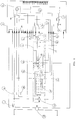
- Figure 1 is a view of a simplified wiring diagram for a clothes washing machine provided with a traditional type of PTC-based door interlock arrangement, as improved according to the present invention;
- Figure 2 is a view of a wiring diagram which is similar to the one shown in Figure 1, but intended for a clothes washing machine provided with a door interlock arrangement of the instantaneous type.
- In Figure 1, the
reference numeral 1 is used to indicate the main on/off switch of the clothes washing machine, thereference numeral 2 to indicate the electrical contact of the door interlock device, thereference numeral 3 to indicate the PTC element of the door interlock arrangement, thereference numeral 4 to indicate the electronic control module of the clothes washing machine, thereference numeral 5 to indicate the general relay of the machine, thereference numeral 6 to indicate a tachometer adapted to measure the revolutions per minute of the driving motor and, hence, of the rotating drum of the machine, thereference numeral 7 to indicate the stator of the motor rotatably driving the rotating drum of the machine, thereference numeral 8 to indicate the rotor of the same motor, thereference numeral 9 to indicate the electric portion of the programme sequence control switch governing the operational elements of the clothes washing machine and, in particular, the inlet water flow distributing arrangement (not shown), thereference numeral 10 to indicate the power contacts of said programme sequence control switch, thereference numeral 11 to indicate the wiping contacts equipping the programme sequence control switch to control the positioning of the inlet water flow distributing arrangement, thereference numeral 12 to indicate an electrical RFI suppressing filter, thereference numeral 13 the driving motor of the programme sequence control switch, thereference numeral 14 to indicate the various connections of the programme sequence control switch with the functional elements of the machine (such as electromagnetic valves, pumps and the like), thereference numeral 15 to indicate the wiping contacts euipping the programme sequence control switch to control said functional elements of the machine, thereference numeral 16 to indicate the relay controlling the reversing action of the rotating drum, thereference numeral 17 to indicate the microprocessor included in theelectronic control module 4 of the machine, thereference numeral 18 to indicate the electronic switch (Triac) of the motor driving the programme sequence control switch, and thereference numeral 19 to indicate the electronic switch (Triac) of the motor driving the rotating drum of the machine. - It should be noticed that, according to the present invention, the
wiping contacts 11 are additionally used to identify, through counting, all of the electrical positions taken by the programme sequence control switch while going through the various cycles, as this will be explained in greater detail further on. - In Figure 2, which illustrates the electrical schematics of a clothes washing machine equipped with a door interlock arrangement of the instantaneous type, the only variant appearing as compared to Figure 1 is represented by the coil 22 (which replaces the PTC element 3) of the door interlock arrangement and the corresponding electrical connection with the
electronic control module 4. All other component parts are identical to the ones appearing in Figure 1, so that they are indicated using the same reference numerals. - All such elements are normally provided and used in the control and regulation circuitry of an electronically controlled clothes washing machine.
- According to the present invention, however, some of such elements are connected, in the two illustrated embodiments, in a new and original manner to reach the previously indicated aims and advantages.
- In Figure 1, in fact, the
PTC element 3 of the door interlock arrangement is connected to the Triac 19 via aconnection terminal 24 of theelectronic control module 4. Thedrum driving motor contact 25 of the programme sequence control switch, and thereversing relay 16, is also connected, via saidreversing relay 16, with thegeneral relay 5 and theelectric contact 2 of the door interlock arrangement, via a switch-overcontact 26. - For the door to be effectively locked, it is necessary that the
PTC element 3 be energized either continuously or intermittently, whereas in the latter case the interval shall however be shorter than its release time (usually ≦1.5 minutes). By taking advantage of this delay time, it is therefore possible to keep the door locked by simply letting the drum of the washing machine rotate according to an appropriately selected rhythm. - The solution according to the present invention, however, enables the door to be kept locked even without the need for the drum to be driven. This is possible through the
contact 26 being switched over so as to divert the power supply from thedriving motor relay 5. In this particular situation, all other electric elements of the washing machine are de-energized, so that such a condition may be only brought about in well-determined phases of an operational cycle (for instance, in the "pre-soak" phase, in which the clothes, and in particular the delicate ones, have to be kept immersed in water for a certain period of time, without any rotation of the drum). - Should the Triac 19 of the
drum driving motor microprocessor 17 will activate therelay 5 by switching over thecontact 26 so as to remove the power supply from themotor PTC element 3 has been duly allowed to elapse. In other words, it can conclusively be said that when therelay 5 is de-energized (switch-overcontact 26 in the position shown in Figure 1) and the Triac 19 is operating regularly, both thedoor interlock arrangement relay 5 is energized (contact 26 switched over from the position shown in Figure 1) along with the Triac, thedoor interlock arrangement motor 13 of the programme sequence control switch, while all other functional elements of the washing machine are however de-energized, ie. separated from the power supply. - In the embodiment illustrated in Figure 2, in which a door interlock arrangement of the so-called instantaneous type is used, the specific situations are different, but they anyway ensure the same function. In fact, if the Triac 19 suffers a short-circuit condition, the
microprocessor 17 will detect such a condition on the basis of the signal delivered by thetachometer 6. Under the circumstances, themicroprocessor 17 cannot energize therelay 5 and, as a consequence, de-energize thedrum driving motor motor microprocessor 17 will therefore energize the drivingmotor 13 of the programme sequence control switch until thecontact 25 is brought to its opening position. Thedrum driving motor microprocessor 17 will activate the relay 5 (by switching over thecontact 26 from the position shown in Figure 2), thereby energizing thecoil 22 that will open theswitch 2 of the drum loading door. - Therefore, it can conclusively be said that when the
relay 5 is energized (contact 26 switched over from the position shown in Figure 2) and the Triac 19 is not operating, the door interlock arrangement is energized, while the functional elements of the washing machine are separated from the power supply. When therelay 5 is on the contrary de-energized (contact 26 in the position shown in Figure 2) and the Triac is in any of its conditions, both the door interlock arrangement and the functional elements of the washing machine are energized. - The electric circuits appearing in Figures 1 and 2 emphasize a further innovatory feature which is capable of increasing both the simplicity and the reliability of the control arrangements of a clothes washing machine. As it can be noticed in the Figures, the
wiping contacts 11 controlling the positioning of the inlet water flow distributor are connected to theelectronic control module 4 and, as a consequence, themicroprocessor 17, via twoconnection lines - Such a solution enables, through only two 220-volt signals coming from the
contacts 11, various positions corresponding to the main phases of the operational cycles of the machine (ie. pre-wash/rinses, main wash, drying, etc.) to be recognized. Within each one of such phases there may be several positions of electrical actuation which themicroprocessor 17 is able to recognize through a simple counting starting from the first one. - During a cycle, the
microprocessor 17 is capable to recognize the starting position of a phase and can shift the corresponding actuator to the desired position; any subsequent shifting will be made forward and/or backward with respect to that position, using per sè known means, based on said counting. - Should there be a power supply failure for any reason whatsoever, the
microprocessor 17, after the power supply has been duly restored, will start from the current position and shift the inlet water flow distributor backward until a change of phase is read. This is needed by themicroprocessor 17 in order to be able to identify the position in a univocal manner. A solution like this, which may for instance comprise a mechanical phase indicator means (flange), arranged coaxially with respect to the camshaft of the programme sequence control switch, and a clutch means being adapted to only act when the shaft is rotated clockwise, enables such an identification of position to be made without altering the associated phase indication. - Conclusively, the described solution enables various positions (of the inlet water flow distributor, the current cycle phase being performed, the electric contacts of the various functional elements of the machine, and the like) to be recognized by only using two connection lines to the microprocessor. Furthermore, the signals coming from the water flow
distributor position contacts 11 are more reliable since the latter are energized with alternating current at 220 Volts reducing oxidation problems. - It will be appreciated that the described circuits may undergo any modification or variation as considered to be appropriate, without departing from the scope of the present invention as defined in the appended claims.
Claims (5)
- Clothes washing machine of the rotating-drum type, comprising at least an arrangement (2, 3) adapted to lock the drum loading door, an inlet water flow distributor to direct the water flow so as to flush the various compartments containing detergent and additives of the detergent dispenser, a motor (7, 8) to rotatably drive the drum, an electromechanical programme sequence control switch (9-15), and an electronic control arrangement (4) comprising a main relay (5), a drum rotation reversing relay (16), a microprocessor (17) and an electronic motor-control switch (19), characterized in that the driving motor (13) of the programme sequence control switch is functionally associated, via the microprocessor (17) and the main relay (5), with two position signals (20, 21) coming from respective contacts (11) of the programme sequence control switch, as well as with the door interlock arrangement (2, 3) and the electronic switch (19) of the motor (7, 8).
- Clothes washing machine according to claim 1, characterized in that the signals (20, 21) of the contacts (11), in combination with the counting performed by the microprocessor (17), further constitute the means for recognizing the phases of the operational cycle performed by the machine.
- Clothes washing machine according to claim 1 or 2, characterized in that the signals (20, 21), in combination with the counting performed by the microprocessor (17), are associated to the motion of the motor (13) to form the means for identifying the phase of the cycle in the case of the power supply to the washing machine being restored after a failure.
- Clothes washing machine according to claim 1, wherein the door interlock arrangement is of the delayed type, characterized in that the door interlock arrangement (2, 3) and the drum driving motor (7, 8) are connected to the main relay (5) via a switch-over contact (26).
- Clothes washing machine according to claim 1, wherein the door interlock arrangement is of the instantaneous type, characterized in that the coil (22) of the door interlock arrangement is directly connected to the electronic switch (19) of the motor (7, 8) via a terminal (24) of the electronic control module (4), and is further connected to the main relay (5) via a switch-over contact (26).
Applications Claiming Priority (2)
| Application Number | Priority Date | Filing Date | Title |
|---|---|---|---|
| IT94PN000052A IT1267583B1 (en) | 1994-09-13 | 1994-09-13 | LAUNDRY WASHING MACHINE WITH PERFECTED COMMAND AND CONTROL DEVICES |
| ITPN940052 | 1994-09-13 |
Publications (2)
| Publication Number | Publication Date |
|---|---|
| EP0702103A1 true EP0702103A1 (en) | 1996-03-20 |
| EP0702103B1 EP0702103B1 (en) | 1998-12-02 |
Family
ID=11394944
Family Applications (1)
| Application Number | Title | Priority Date | Filing Date |
|---|---|---|---|
| EP95112638A Expired - Lifetime EP0702103B1 (en) | 1994-09-13 | 1995-08-11 | Improvement in the control arrangement of a clothes washing machine |
Country Status (4)
| Country | Link |
|---|---|
| EP (1) | EP0702103B1 (en) |
| DE (1) | DE69506345T2 (en) |
| ES (1) | ES2127440T3 (en) |
| IT (1) | IT1267583B1 (en) |
Cited By (13)
| Publication number | Priority date | Publication date | Assignee | Title |
|---|---|---|---|---|
| EP1099790A3 (en) * | 1999-11-09 | 2002-08-21 | Diehl AKO Stiftung & Co. KG | Controlling device for a washing machine or a laundry dryer |
| EP1775366A1 (en) * | 2005-10-17 | 2007-04-18 | Diehl AKO Stiftung & Co. KG | Control circuit for fabric treatment devices |
| EP1962011A1 (en) | 2007-02-26 | 2008-08-27 | Diehl AKO Stiftung & Co. KG | Device with controllable protection device |
| DE102007037767A1 (en) | 2007-02-26 | 2008-08-28 | Diehl Ako Stiftung & Co. Kg | Device with controllable protective device |
| EP1986062A1 (en) * | 2007-04-23 | 2008-10-29 | Diehl AKO Stiftung & Co. KG | Control device and control method for an electric domestic appliance |
| WO2009000690A1 (en) * | 2007-06-26 | 2008-12-31 | Arcelik Anonim Sirketi | A washer/dryer |
| WO2009007380A1 (en) * | 2007-07-10 | 2009-01-15 | Elmarc Societa' Per Azioni | System and electronic circuit used to protect the door of washing machines or washer-driers |
| WO2008148788A3 (en) * | 2007-06-05 | 2009-04-09 | Arcelik As | A washer/dryer |
| DE102007031882A1 (en) | 2007-07-09 | 2009-04-30 | Diehl Ako Stiftung & Co. Kg | Laundry treatment device i.e. washing machine, has door locking element connected with switch via field winding and commutating throttle of drive motor circuit, where door locking element and motor circuit are attached to power lines |
| WO2010063564A1 (en) * | 2008-12-03 | 2010-06-10 | Arcelik Anonim Sirketi | A household appliance wherein the heating of its pump motor is controlled |
| WO2012038311A3 (en) * | 2010-09-22 | 2012-05-18 | Arcelik Anonim Sirketi | Door lock for a washing machine |
| JP2014161486A (en) * | 2013-02-25 | 2014-09-08 | Toshiba Corp | Laundry equipment |
| JP2018027445A (en) * | 2017-11-28 | 2018-02-22 | 東芝ライフスタイル株式会社 | Laundry equipment |
Citations (9)
| Publication number | Priority date | Publication date | Assignee | Title |
|---|---|---|---|---|
| FR1553999A (en) * | 1966-12-29 | 1969-01-17 | ||
| FR1555955A (en) * | 1967-01-31 | 1969-01-31 | ||
| FR2336509A1 (en) * | 1975-12-23 | 1977-07-22 | Miele & Cie | Washing machine program control system - has electronic control unit connected to mechanical stepping unit and is adapted for selecting and displaying program |
| GB2048314A (en) * | 1979-05-14 | 1980-12-10 | Ti Domestic Appliances Ltd | Improvements In and Relating To Electrical Machines |
| GB2128283A (en) | 1982-10-04 | 1984-04-26 | Texas Instruments Italia Spa | Safety locking devices for doors of washing machines and the like |
| DE3303992A1 (en) * | 1983-02-05 | 1984-08-09 | Miele & Cie GmbH & Co, 4830 Gütersloh | Programme switching mechanism for washing machines and dishwashers |
| EP0253710A1 (en) | 1986-07-10 | 1988-01-20 | Ciapem | Programmer for control of washing machine with a microprocessor and electromechanical componant |
| EP0504545A1 (en) | 1991-02-27 | 1992-09-23 | ELECTROLUX ZANUSSI ELETTRODOMESTICI S.p.A. | Arrangement for controlling detergent addition in washing machines |
| EP0522302A1 (en) * | 1991-06-26 | 1993-01-13 | Zanussi Elettrodomestici S.p.A. | Control arrangement for washing machines |
-
1994
- 1994-09-13 IT IT94PN000052A patent/IT1267583B1/en active IP Right Grant
-
1995
- 1995-08-11 EP EP95112638A patent/EP0702103B1/en not_active Expired - Lifetime
- 1995-08-11 DE DE69506345T patent/DE69506345T2/en not_active Expired - Fee Related
- 1995-08-11 ES ES95112638T patent/ES2127440T3/en not_active Expired - Lifetime
Patent Citations (9)
| Publication number | Priority date | Publication date | Assignee | Title |
|---|---|---|---|---|
| FR1553999A (en) * | 1966-12-29 | 1969-01-17 | ||
| FR1555955A (en) * | 1967-01-31 | 1969-01-31 | ||
| FR2336509A1 (en) * | 1975-12-23 | 1977-07-22 | Miele & Cie | Washing machine program control system - has electronic control unit connected to mechanical stepping unit and is adapted for selecting and displaying program |
| GB2048314A (en) * | 1979-05-14 | 1980-12-10 | Ti Domestic Appliances Ltd | Improvements In and Relating To Electrical Machines |
| GB2128283A (en) | 1982-10-04 | 1984-04-26 | Texas Instruments Italia Spa | Safety locking devices for doors of washing machines and the like |
| DE3303992A1 (en) * | 1983-02-05 | 1984-08-09 | Miele & Cie GmbH & Co, 4830 Gütersloh | Programme switching mechanism for washing machines and dishwashers |
| EP0253710A1 (en) | 1986-07-10 | 1988-01-20 | Ciapem | Programmer for control of washing machine with a microprocessor and electromechanical componant |
| EP0504545A1 (en) | 1991-02-27 | 1992-09-23 | ELECTROLUX ZANUSSI ELETTRODOMESTICI S.p.A. | Arrangement for controlling detergent addition in washing machines |
| EP0522302A1 (en) * | 1991-06-26 | 1993-01-13 | Zanussi Elettrodomestici S.p.A. | Control arrangement for washing machines |
Cited By (22)
| Publication number | Priority date | Publication date | Assignee | Title |
|---|---|---|---|---|
| EP1099790A3 (en) * | 1999-11-09 | 2002-08-21 | Diehl AKO Stiftung & Co. KG | Controlling device for a washing machine or a laundry dryer |
| EP1775366A1 (en) * | 2005-10-17 | 2007-04-18 | Diehl AKO Stiftung & Co. KG | Control circuit for fabric treatment devices |
| US7420345B2 (en) | 2005-10-17 | 2008-09-02 | Diehl Ako Stiftung & Co. Kg | Circuit for driving an appliance for treating laundry |
| CN1952249B (en) * | 2005-10-17 | 2011-04-27 | 迪尔阿扣基金两合公司 | Control circuit for fabric treatment devices |
| US7856854B2 (en) | 2007-02-26 | 2010-12-28 | Diehl Ako Stiftung & Co. Kg | Appliance with a controllable protection device |
| EP1962011A1 (en) | 2007-02-26 | 2008-08-27 | Diehl AKO Stiftung & Co. KG | Device with controllable protection device |
| DE102007037767A1 (en) | 2007-02-26 | 2008-08-28 | Diehl Ako Stiftung & Co. Kg | Device with controllable protective device |
| CN101255646B (en) * | 2007-02-26 | 2012-01-04 | 迪尔阿扣基金两合公司 | Appliance with a controllable protection device |
| CN101295166B (en) * | 2007-04-23 | 2012-04-25 | 迪尔阿扣基金两合公司 | Control device and control method for an electric domestic appliance |
| EP1986062A1 (en) * | 2007-04-23 | 2008-10-29 | Diehl AKO Stiftung & Co. KG | Control device and control method for an electric domestic appliance |
| US8286287B2 (en) | 2007-04-23 | 2012-10-16 | Diehl Ako Stiftung & Co. Kg | Control apparatus and control method for an electrical domestic applicance |
| WO2008148788A3 (en) * | 2007-06-05 | 2009-04-09 | Arcelik As | A washer/dryer |
| WO2009000690A1 (en) * | 2007-06-26 | 2008-12-31 | Arcelik Anonim Sirketi | A washer/dryer |
| US20100175431A1 (en) * | 2007-06-26 | 2010-07-15 | Kerem Erenay | Washer/dryer |
| US8590346B2 (en) | 2007-06-26 | 2013-11-26 | Arcelik Anonim Sirketi | Washer/dryer |
| DE102007031882A1 (en) | 2007-07-09 | 2009-04-30 | Diehl Ako Stiftung & Co. Kg | Laundry treatment device i.e. washing machine, has door locking element connected with switch via field winding and commutating throttle of drive motor circuit, where door locking element and motor circuit are attached to power lines |
| DE102007031882B4 (en) * | 2007-07-09 | 2016-07-21 | Diehl Ako Stiftung & Co. Kg | Laundry treatment device with door locking element |
| WO2009007380A1 (en) * | 2007-07-10 | 2009-01-15 | Elmarc Societa' Per Azioni | System and electronic circuit used to protect the door of washing machines or washer-driers |
| WO2010063564A1 (en) * | 2008-12-03 | 2010-06-10 | Arcelik Anonim Sirketi | A household appliance wherein the heating of its pump motor is controlled |
| WO2012038311A3 (en) * | 2010-09-22 | 2012-05-18 | Arcelik Anonim Sirketi | Door lock for a washing machine |
| JP2014161486A (en) * | 2013-02-25 | 2014-09-08 | Toshiba Corp | Laundry equipment |
| JP2018027445A (en) * | 2017-11-28 | 2018-02-22 | 東芝ライフスタイル株式会社 | Laundry equipment |
Also Published As
| Publication number | Publication date |
|---|---|
| ITPN940052A0 (en) | 1994-09-13 |
| DE69506345D1 (en) | 1999-01-14 |
| ITPN940052A1 (en) | 1996-03-13 |
| ES2127440T3 (en) | 1999-04-16 |
| EP0702103B1 (en) | 1998-12-02 |
| IT1267583B1 (en) | 1997-02-07 |
| DE69506345T2 (en) | 1999-04-29 |
Similar Documents
| Publication | Publication Date | Title |
|---|---|---|
| EP0702103B1 (en) | Improvement in the control arrangement of a clothes washing machine | |
| EP0504545B1 (en) | Arrangement for controlling detergent addition in washing machines | |
| CA2071330C (en) | Control system for appliance indicator light and method for using same | |
| EP0027432B2 (en) | Electronic data memorising circuit in a domestic electrical appliance | |
| CA2190307A1 (en) | Dishwasher and control therefor | |
| US20010030482A1 (en) | Clutchless motor drive system | |
| US7973431B2 (en) | Circuit arrangement for locking and/or unlocking a door lock, especially in an electric appliance | |
| US4942346A (en) | Circuit for controlling rotational direction and rotational speed of an electric motor | |
| EP0593978B1 (en) | Dishwashing machine with water fill control | |
| EP0518147B1 (en) | Door interlock device for clothes washing and/or drying machines | |
| US3111830A (en) | Automatic clothes washing machine with lid switch control | |
| CN101688355A (en) | a washer/dryer | |
| US3140595A (en) | Control circuit for clothes washing machine | |
| EP0808935A2 (en) | Washing machine with instant-action door interlock arrangement | |
| EP0429949B1 (en) | Automatic laundry washer of the rotating drum type | |
| EP0522302B1 (en) | Control arrangement for washing machines | |
| US5889244A (en) | Dishwasher sequence switch unit | |
| EP0387942A1 (en) | Method and device for locking the drum of a top-loading washing machine in a suitable position | |
| EP0381022B1 (en) | A door locking means for a washing and/or drying machine for laundry | |
| EP0224776B1 (en) | Automatic washing machine with rotating drum | |
| KR0126458B1 (en) | Control apparatus for a compressor | |
| EP2387630B1 (en) | A household appliance with increased safety control | |
| US3934433A (en) | Switching control for a reversing motor of a washing machine | |
| JPS58216093A (en) | Drum type washer | |
| JPS62261393A (en) | Dehydrating washing machine |
Legal Events
| Date | Code | Title | Description |
|---|---|---|---|
| PUAI | Public reference made under article 153(3) epc to a published international application that has entered the european phase |
Free format text: ORIGINAL CODE: 0009012 |
|
| AK | Designated contracting states |
Kind code of ref document: A1 Designated state(s): DE ES FR GB IT |
|
| 17P | Request for examination filed |
Effective date: 19960518 |
|
| 17Q | First examination report despatched |
Effective date: 19970613 |
|
| RAP1 | Party data changed (applicant data changed or rights of an application transferred) |
Owner name: ELECTROLUX ZANUSSI S.P.A. |
|
| GRAG | Despatch of communication of intention to grant |
Free format text: ORIGINAL CODE: EPIDOS AGRA |
|
| GRAG | Despatch of communication of intention to grant |
Free format text: ORIGINAL CODE: EPIDOS AGRA |
|
| GRAH | Despatch of communication of intention to grant a patent |
Free format text: ORIGINAL CODE: EPIDOS IGRA |
|
| ITF | It: translation for a ep patent filed | ||
| GRAH | Despatch of communication of intention to grant a patent |
Free format text: ORIGINAL CODE: EPIDOS IGRA |
|
| GRAA | (expected) grant |
Free format text: ORIGINAL CODE: 0009210 |
|
| AK | Designated contracting states |
Kind code of ref document: B1 Designated state(s): DE ES FR GB IT |
|
| REF | Corresponds to: |
Ref document number: 69506345 Country of ref document: DE Date of ref document: 19990114 |
|
| ET | Fr: translation filed | ||
| REG | Reference to a national code |
Ref country code: ES Ref legal event code: FG2A Ref document number: 2127440 Country of ref document: ES Kind code of ref document: T3 |
|
| PLBE | No opposition filed within time limit |
Free format text: ORIGINAL CODE: 0009261 |
|
| STAA | Information on the status of an ep patent application or granted ep patent |
Free format text: STATUS: NO OPPOSITION FILED WITHIN TIME LIMIT |
|
| 26N | No opposition filed | ||
| REG | Reference to a national code |
Ref country code: GB Ref legal event code: IF02 |
|
| PGFP | Annual fee paid to national office [announced via postgrant information from national office to epo] |
Ref country code: IT Payment date: 20060831 Year of fee payment: 12 |
|
| PGFP | Annual fee paid to national office [announced via postgrant information from national office to epo] |
Ref country code: DE Payment date: 20070718 Year of fee payment: 13 |
|
| PGFP | Annual fee paid to national office [announced via postgrant information from national office to epo] |
Ref country code: ES Payment date: 20070808 Year of fee payment: 13 |
|
| PGFP | Annual fee paid to national office [announced via postgrant information from national office to epo] |
Ref country code: GB Payment date: 20070717 Year of fee payment: 13 |
|
| PGFP | Annual fee paid to national office [announced via postgrant information from national office to epo] |
Ref country code: FR Payment date: 20070712 Year of fee payment: 13 |
|
| GBPC | Gb: european patent ceased through non-payment of renewal fee |
Effective date: 20080811 |
|
| REG | Reference to a national code |
Ref country code: FR Ref legal event code: ST Effective date: 20090430 |
|
| PG25 | Lapsed in a contracting state [announced via postgrant information from national office to epo] |
Ref country code: FR Free format text: LAPSE BECAUSE OF NON-PAYMENT OF DUE FEES Effective date: 20080901 Ref country code: DE Free format text: LAPSE BECAUSE OF NON-PAYMENT OF DUE FEES Effective date: 20090303 |
|
| PG25 | Lapsed in a contracting state [announced via postgrant information from national office to epo] |
Ref country code: IT Free format text: LAPSE BECAUSE OF NON-PAYMENT OF DUE FEES Effective date: 20070811 |
|
| REG | Reference to a national code |
Ref country code: ES Ref legal event code: FD2A Effective date: 20080812 |
|
| PG25 | Lapsed in a contracting state [announced via postgrant information from national office to epo] |
Ref country code: GB Free format text: LAPSE BECAUSE OF NON-PAYMENT OF DUE FEES Effective date: 20080811 |
|
| PG25 | Lapsed in a contracting state [announced via postgrant information from national office to epo] |
Ref country code: ES Free format text: LAPSE BECAUSE OF NON-PAYMENT OF DUE FEES Effective date: 20080812 |