EP0701679B1 - Panel for regenerative heat-exchangers - Google Patents
Panel for regenerative heat-exchangers Download PDFInfo
- Publication number
- EP0701679B1 EP0701679B1 EP93913335A EP93913335A EP0701679B1 EP 0701679 B1 EP0701679 B1 EP 0701679B1 EP 93913335 A EP93913335 A EP 93913335A EP 93913335 A EP93913335 A EP 93913335A EP 0701679 B1 EP0701679 B1 EP 0701679B1
- Authority
- EP
- European Patent Office
- Prior art keywords
- mesh
- heat exchange
- wall member
- encapsulating layer
- element according
- Prior art date
- Legal status (The legal status is an assumption and is not a legal conclusion. Google has not performed a legal analysis and makes no representation as to the accuracy of the status listed.)
- Expired - Lifetime
Links
- 230000001172 regenerating effect Effects 0.000 title claims description 16
- 239000000463 material Substances 0.000 claims abstract description 43
- 229910052751 metal Inorganic materials 0.000 claims abstract description 26
- 239000002184 metal Substances 0.000 claims abstract description 24
- 239000002131 composite material Substances 0.000 claims abstract description 18
- 239000004033 plastic Substances 0.000 claims abstract description 17
- 229920003023 plastic Polymers 0.000 claims abstract description 17
- 230000007797 corrosion Effects 0.000 claims abstract description 5
- 238000005260 corrosion Methods 0.000 claims abstract description 5
- 239000011324 bead Substances 0.000 claims abstract description 4
- 230000002093 peripheral effect Effects 0.000 claims abstract description 4
- 239000012530 fluid Substances 0.000 claims description 15
- 239000011521 glass Substances 0.000 claims description 5
- 238000010521 absorption reaction Methods 0.000 claims description 4
- 230000000694 effects Effects 0.000 claims description 4
- 239000002253 acid Substances 0.000 claims description 3
- 229910052500 inorganic mineral Inorganic materials 0.000 claims description 3
- 239000011707 mineral Substances 0.000 claims description 3
- 230000003014 reinforcing effect Effects 0.000 claims description 3
- 238000000926 separation method Methods 0.000 claims description 3
- 239000000126 substance Substances 0.000 claims description 3
- 239000000428 dust Substances 0.000 claims description 2
- 238000005338 heat storage Methods 0.000 claims description 2
- 239000007787 solid Substances 0.000 claims description 2
- 239000007769 metal material Substances 0.000 claims 2
- 239000007789 gas Substances 0.000 description 23
- 230000002745 absorbent Effects 0.000 description 4
- 239000002250 absorbent Substances 0.000 description 4
- 239000004411 aluminium Substances 0.000 description 3
- 229910052782 aluminium Inorganic materials 0.000 description 3
- XAGFODPZIPBFFR-UHFFFAOYSA-N aluminium Chemical compound [Al] XAGFODPZIPBFFR-UHFFFAOYSA-N 0.000 description 3
- IJGRMHOSHXDMSA-UHFFFAOYSA-N Atomic nitrogen Chemical compound N#N IJGRMHOSHXDMSA-UHFFFAOYSA-N 0.000 description 2
- RYGMFSIKBFXOCR-UHFFFAOYSA-N Copper Chemical compound [Cu] RYGMFSIKBFXOCR-UHFFFAOYSA-N 0.000 description 2
- PXHVJJICTQNCMI-UHFFFAOYSA-N Nickel Chemical compound [Ni] PXHVJJICTQNCMI-UHFFFAOYSA-N 0.000 description 2
- 229910000831 Steel Inorganic materials 0.000 description 2
- 239000010949 copper Substances 0.000 description 2
- 229910052802 copper Inorganic materials 0.000 description 2
- KWGKDLIKAYFUFQ-UHFFFAOYSA-M lithium chloride Chemical compound [Li+].[Cl-] KWGKDLIKAYFUFQ-UHFFFAOYSA-M 0.000 description 2
- 150000002739 metals Chemical class 0.000 description 2
- 239000000843 powder Substances 0.000 description 2
- 239000010959 steel Substances 0.000 description 2
- 229910001369 Brass Inorganic materials 0.000 description 1
- 229910000906 Bronze Inorganic materials 0.000 description 1
- JOYRKODLDBILNP-UHFFFAOYSA-N Ethyl urethane Chemical compound CCOC(N)=O JOYRKODLDBILNP-UHFFFAOYSA-N 0.000 description 1
- 239000004677 Nylon Substances 0.000 description 1
- NINIDFKCEFEMDL-UHFFFAOYSA-N Sulfur Chemical compound [S] NINIDFKCEFEMDL-UHFFFAOYSA-N 0.000 description 1
- 239000005864 Sulphur Substances 0.000 description 1
- 239000010951 brass Substances 0.000 description 1
- 239000010974 bronze Substances 0.000 description 1
- 239000003795 chemical substances by application Substances 0.000 description 1
- 238000002485 combustion reaction Methods 0.000 description 1
- 239000004020 conductor Substances 0.000 description 1
- KUNSUQLRTQLHQQ-UHFFFAOYSA-N copper tin Chemical compound [Cu].[Sn] KUNSUQLRTQLHQQ-UHFFFAOYSA-N 0.000 description 1
- 230000032798 delamination Effects 0.000 description 1
- 229920001971 elastomer Polymers 0.000 description 1
- 239000000806 elastomer Substances 0.000 description 1
- 239000000446 fuel Substances 0.000 description 1
- 230000012010 growth Effects 0.000 description 1
- 229910052759 nickel Inorganic materials 0.000 description 1
- 229910052757 nitrogen Inorganic materials 0.000 description 1
- 229920001778 nylon Polymers 0.000 description 1
- 229920001169 thermoplastic Polymers 0.000 description 1
- 229920001187 thermosetting polymer Polymers 0.000 description 1
- 239000004416 thermosoftening plastic Substances 0.000 description 1
Images
Classifications
-
- F—MECHANICAL ENGINEERING; LIGHTING; HEATING; WEAPONS; BLASTING
- F28—HEAT EXCHANGE IN GENERAL
- F28F—DETAILS OF HEAT-EXCHANGE AND HEAT-TRANSFER APPARATUS, OF GENERAL APPLICATION
- F28F19/00—Preventing the formation of deposits or corrosion, e.g. by using filters or scrapers
- F28F19/02—Preventing the formation of deposits or corrosion, e.g. by using filters or scrapers by using coatings, e.g. vitreous or enamel coatings
-
- F—MECHANICAL ENGINEERING; LIGHTING; HEATING; WEAPONS; BLASTING
- F28—HEAT EXCHANGE IN GENERAL
- F28D—HEAT-EXCHANGE APPARATUS, NOT PROVIDED FOR IN ANOTHER SUBCLASS, IN WHICH THE HEAT-EXCHANGE MEDIA DO NOT COME INTO DIRECT CONTACT
- F28D19/00—Regenerative heat-exchange apparatus in which the intermediate heat-transfer medium or body is moved successively into contact with each heat-exchange medium
- F28D19/04—Regenerative heat-exchange apparatus in which the intermediate heat-transfer medium or body is moved successively into contact with each heat-exchange medium using rigid bodies, e.g. mounted on a movable carrier
-
- F—MECHANICAL ENGINEERING; LIGHTING; HEATING; WEAPONS; BLASTING
- F28—HEAT EXCHANGE IN GENERAL
- F28D—HEAT-EXCHANGE APPARATUS, NOT PROVIDED FOR IN ANOTHER SUBCLASS, IN WHICH THE HEAT-EXCHANGE MEDIA DO NOT COME INTO DIRECT CONTACT
- F28D19/00—Regenerative heat-exchange apparatus in which the intermediate heat-transfer medium or body is moved successively into contact with each heat-exchange medium
- F28D19/04—Regenerative heat-exchange apparatus in which the intermediate heat-transfer medium or body is moved successively into contact with each heat-exchange medium using rigid bodies, e.g. mounted on a movable carrier
- F28D19/041—Regenerative heat-exchange apparatus in which the intermediate heat-transfer medium or body is moved successively into contact with each heat-exchange medium using rigid bodies, e.g. mounted on a movable carrier with axial flow through the intermediate heat-transfer medium
- F28D19/042—Rotors; Assemblies of heat absorbing masses
-
- F—MECHANICAL ENGINEERING; LIGHTING; HEATING; WEAPONS; BLASTING
- F28—HEAT EXCHANGE IN GENERAL
- F28F—DETAILS OF HEAT-EXCHANGE AND HEAT-TRANSFER APPARATUS, OF GENERAL APPLICATION
- F28F21/00—Constructions of heat-exchange apparatus characterised by the selection of particular materials
Definitions
- the present invention relates to a heat exchange panel or element adapted for use in a regenerative or recuperative type heat exchanger and such as may be used in packages of many such panels or elements within a regenerative or recuperative gas to gas, vapour bearing gas to gas or gas or vapour bearing gas to air heat exchanger of the well known Ljungstrom or similar type.
- a body of sheet elements or panels is alternately exposed to passage through the interstitial spaces between the individual elements of a hotter flow of gas or gas and vapour and a cooler flow of gas,gas and vapour or air. It is the purpose of the elements or panels to accept and store heat energy as rapidly as possible from the hotter flow and when after a time interval a cooler flow is directed through the same interstitial spaces to give out the stored heat energy to the cooler flow thus raising the temperature of that flow.
- the elements or panels may be rotated or translated in such a way that they proceed alternately through the hotter and cooler flows. Alternatively the elements or panels may be stationary and the hotter and cooler flows respectively directed by means of dampers to pass alternately through the elements or panels.
- This invention has application for such regenerative and recuperative gas to gas or gas to air heat exchangers particularly, but not exclusively, where one or both of the gas flows, or the gas flow, contains vapours at or near their condensing temperatures or dew point and which vapours are corrosive to certain metals and other materials and which may be in a particular instance oxides of sulphur and of nitrogen as produced during the combustion of fossil and other fuels.
- GB-A-2099973 discloses a thermal regenerator for exchanging heat between two fluid streams.
- a fluid permeable mass of heat transfer material is formed by a multiplicity of parallel, non-planar, layers of thermally absorbing fluid porous or permeable material.
- Each layer comprises components of different thermal conductivity.
- a first component of each layer of higher thermal conductivity and corrosion resistant comprises expanded sheet, perforated sheet or an open mesh of woven, knitted or felted fibres, strands or wires.
- a second component of lower thermal conductivity envelopes the first component so that the latter component is encapsulated within the second component of the layer.
- the two components are intimately interlocked together against separation and the composite layer so formed is a rigid, permeable, integral mass resistant to fatigue failure or other damage from pulsating fluid flow and able to operate at higher temperatures than could the material of the second, encapsulating component alone.
- the encapsulating component is a moisture absorbent plastics material, e.g. nylon, which may in turn be coated on all sides of the first layer (including the openings when the layer comprises expanded sheet metal) with a further moisture absorbent material such as lithium chloride.
- a labyrinth of flow passages is provided by the layers through the fluid permeable mass for fluid flow through the mass.
- the hygroscopic absorbent properties of the second components of the layers are relied upon to improve the total heat transfer capacity of the layers.
- the layers are positioned generally in planes transverse to the direction of the fluid flow through the regenerator.
- the present invention consists in a heat exchange panel or element adapted for use in a regenerative or recuperative heat exchanger comprising a heat storage and transfer member which includes a composite wall member made from portions of different thermal conductivity, one said portion of higher thermal conductivity and forming a reinforcing grid within the wall member comprising a metal mesh of strips or strands and a second portion of lower thermal conductivity constituting an encapsulating layer enveloping and extending through the mesh so that the mesh is contained within the encapsulating layer, the portions are intimately interlocked together against separation, the composite wall member is enabled to operate at higher temperatures than could the material of the encapsulating layer alone and at least some of the mesh continues longitudinally and directly throughout the major part of the length and breadth of the wall member, characterised in that the composite wall member is imperforate, the encapsulating layer filling the mesh so that the composite wall member is a completely solid imperforate mass resistant to passage of fluid therethrough, at least outside the mesh on both sides of the
- the composite wall member of the heat exchange panel or element in accordance with the invention differs from the layers in the fluid permeable mass of the thermal regenerator disclosed in GB-A-2099973 in that it is not fluid permeable, and the heat absorption of the wall member is promoted by the thinness of the encapsulating layer outside the mesh and not by being of a moisture absorbent material as taught in GB-A-2099973.
- the characterising features of the composite wall member enable the heat exchange panel or element to be used for regenerative hating in an industrial environment in which sever corrosion and fouling can give rise to serious operating problems and inefficiencies, and in which the operating temperature is close to the upper working temperature of the material of the encapsulating layer.
- the encapsulating layer may be composed of a material, such as a plastics, which may or may not be filled with particulated mineral or other substance to provide as high a heat capacity as possible for any given volume or mass of the filled material.
- the thickness of the material of the encapsulating layer outside the mesh is of the order of 0.1-0.3mm.
- the average density of such a metal mesh and plastics composite wall member is considerably less than that of the equivalent metal or glass enamelled metal elements presently in use in the aforementioned Ljungstrom and such heat exchangers whereas the specific heat capacity of the wall member is for any given volume as good as for metal or glass enamelled metal elements.
- the material of the encapsulating layer may be chosen from preferred plastics such as to reduce the adherence and building up of dust or scales on the surfaces of the composite wall member.
- the surfaces of the wall member could be made to be non-fouling in respect of organic and other agents or growths.
- the encapsulating layer may be made of another suitable material of lower thermal conductivity than the metal mesh, if desired, for example glass.
- the metal mesh which forms the heat conducting material within the proposed panel or element, in operating as a reinforcing grid within the composite wall member, imparts structural stability to the panel or element. That stability would not be present if a panel or element of purely plastics material were to be used, and it enables greater rigidity and stability to be imparted to any preferred ridging, folding or other profile forming of the panel or element for it to present undulating surfaces for enhanced heat transfer at those surfaces.
- the mesh may comprise interwoven or overlaid discrete metal strips or strands of wire or filament, for example of steel, aluminium, copper or brass, or it may comprise a sheet of metal, for example of one of the metals just mentioned, which has been pierced and expanded such that the sheet whilst retaining its unity effectively presents a network of strip or strand portions.
- a preferred material is that known as EXPAMET which is metal sheet which has been pierced, expanded and subsequently flattened.
- EXPAMET is metal sheet which has been pierced, expanded and subsequently flattened.
- the percentage open area of such a sheet between the strip or strand portions may vary, typically between 5 and 25% of the total area of the mesh.
- the thickness of the metal of the mesh may vary with the size of the panel or element but typically will be 0.3-1.0mm thick, resulting in a typical total, or laminate, thickness, of the wall member between 0.5 and 1.5mm.
- a regenerative or recuperative type heat exchanger which includes a heat exchange panel or element in accordance with the first aspect of the invention herein set forth, the panel or element being positioned in a plane parallel to the direction of fluid flow through the heat exchanger when in use.
- a regenerative or recuperative heat exchanger of the Ljungstrom or similar type containing a body of heat exchange panels or elements each in accordance with the heat exchange panel or element as set forth in the first aspect of the invention herein, the panels or elements being positioned in planes parallel to the direction of fluid flow through the heat exchanger.
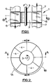
- a regenerative heat exchanger 1 comprises a drum 2 carried by a rotating shaft 3 and including peripheral pockets 4 housing removable heat exchange panels or elements 5.
- the heat exchange panels or elements 5 are arranged in packs in the pockets 4 with the panels or elements of each pack in contiguous relationship but with passages defined between them for the flow of gas, gas and vapour or air for heat exchange with the panels or elements.
- the panels or elements are corrugated, ridged or otherwise suitably profiled for the passages to be defined and for there to be turbulent flow of the gas, gas and vapour or air between the panels or elements.
- the heat exchanger 1 has a heat input side 1A and a heat output side 1B, and suitable ductings 6, 7 are provided for gas, gas and vapour or air flows (shown arrowed) through the drum 2 at these sides for heat exchange with the panels or elements 5.
- the panels or elements 5 are positioned in the pockets 4 in planes parallel to the direction of flow of the gas, gas and vapour or air through the drum.
- the drum 1 is rotated very slowly, e.g. less than 1 r.p.m., by the shaft 3.
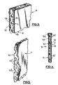
- Each heat exchange panel or element 5 includes, as shown in Figures 3 and 4, an imperforate composite wall member 9 made from portions of different thermal conductivity, one portion of higher thermal conductivity comprising a metal mesh 10 of interwoven wire strands while a further wall portion 11 of lower thermal conductivity constitutes an encapsulating layer which completely covers, extends through and fills the mesh.
- the two portions of the wall are thus soundly mechanically bonded together and so intimately interlocked that delamination of the portions is prevented.
- the covering of the encapsulating layer over the strands of the mesh is reduced to a very thin skin, preferably 0.1-0.3mm thick, which is substantially thinner than the thickness of the mesh and its strands, the skins outside the mesh being fused together by the material of the encapsulating layer through the openings between the strands of the mesh.
- the mesh 10 therefore, has a transverse extent across the depth of the wall member 9 substantially to the opposite outer surfaces or the wall member so that the mesh is able to conduct heat from the outer surfaces of the wall member into the body of the wall member to promote the heat absorption capacity of the wall member.
- the wall member 9 is incorporated, applied and fashioned into the panel or element to be suitable for application to the heat exchanger 1.
- the panel or element 5 includes a peripheral bead 5A around the wall member 9.
- the bead 5A may be omitted, if desired.
- the mesh may be made of strands of copper, aluminium, nickel, bronze or other strand material of high thermal conductivity.
- the encapsulating layer 11 immediately enveloping the mesh strands is composed of a plastics material 12 filled with particulated mineral or other substance to provide as high a heat capacity as possible for any given volume or mass of the filled plastics material.
- the plastics material 12 may be un-filled.
- the encapsulating layer also includes thin outer layers 13 on both sides of the wall member 9 composed of a plastics or other material which inseparably bonds with the plastics material 12, is inert and unaffected by corrosive effects of any condensing vapours or acid gaseous oxides or vapours which may condense upon it.
- the outer layers 13 may be omitted so that the encapsulating layer is composed entirely of the plastics material 12, filled or un-filled, which not only extends through the mesh but provides the thin skins over the strands of the mesh outside the mesh.
- the material of the encapsulating layer 11 may be a thermoplastic or thermosetting plastics having suitable flexibility to permit thermal stressing during use of the panel. It must be able to withstand the highest operational temperatures of the panel. With the mesh contained within it the plastics material is able to operate satisfactorily at temperatures in excess of those at which the material might be expected to function on its own. A urethane or other elastomer is, for example, suitable. Depending upon the type of plastics material used for the encapsulating layer, the material may be applied molten to the mesh, sprayed in the form of a powder on to the mesh or the mesh may be dipped into a bed of the powder fluidised by compressed air to be covered by that material.
- Glass may be used to form the encapsulating layer 11 instead of plastics material.
- the mesh 10 may comprise an arrangement of cross-laid strands 10' as shown in Figure 4.
- the mesh may be made of interwoven or cross-laid sheet metal strips.
- FIG. 5 of the accompanying drawings Another form of the composite wall member 9 is shown in Figure 5 of the accompanying drawings.
- the mesh 10 is formed from pierced and expanded metal sheet which though a unitary piece of material presents a network of strip or strand portions 10" across the length and breadth of the wall member.
- this mesh is formed from pierced, expanded and flattened metal sheet, for example steel or aluminium EXPAMET.
- the mesh is completely covered and filled as in the previously described form of the composite wall member, by the encapsulating layer 11 which also extends through the openings of the mesh to fuse together through the mesh the portions of the encapsulating layer at opposite sides of the mesh sheet and interlock the mesh and encapsulating layer inseparably together.
- the encapsulating layer 11 may include thin outer layers, as in the other embodiments described and illustrated.
Landscapes
- Engineering & Computer Science (AREA)
- Physics & Mathematics (AREA)
- Thermal Sciences (AREA)
- Mechanical Engineering (AREA)
- General Engineering & Computer Science (AREA)
- Heat-Exchange Devices With Radiators And Conduit Assemblies (AREA)
- Laminated Bodies (AREA)
- Filling Or Discharging Of Gas Storage Vessels (AREA)
- Gasket Seals (AREA)
Abstract
Description
- The present invention relates to a heat exchange panel or element adapted for use in a regenerative or recuperative type heat exchanger and such as may be used in packages of many such panels or elements within a regenerative or recuperative gas to gas, vapour bearing gas to gas or gas or vapour bearing gas to air heat exchanger of the well known Ljungstrom or similar type.
- Within Ljungstrom and such heat exchangers a body of sheet elements or panels is alternately exposed to passage through the interstitial spaces between the individual elements of a hotter flow of gas or gas and vapour and a cooler flow of gas,gas and vapour or air. It is the purpose of the elements or panels to accept and store heat energy as rapidly as possible from the hotter flow and when after a time interval a cooler flow is directed through the same interstitial spaces to give out the stored heat energy to the cooler flow thus raising the temperature of that flow. The elements or panels may be rotated or translated in such a way that they proceed alternately through the hotter and cooler flows. Alternatively the elements or panels may be stationary and the hotter and cooler flows respectively directed by means of dampers to pass alternately through the elements or panels.
- This invention has application for such regenerative and recuperative gas to gas or gas to air heat exchangers particularly, but not exclusively, where one or both of the gas flows, or the gas flow, contains vapours at or near their condensing temperatures or dew point and which vapours are corrosive to certain metals and other materials and which may be in a particular instance oxides of sulphur and of nitrogen as produced during the combustion of fossil and other fuels.
- GB-A-2099973 discloses a thermal regenerator for exchanging heat between two fluid streams. A fluid permeable mass of heat transfer material is formed by a multiplicity of parallel, non-planar, layers of thermally absorbing fluid porous or permeable material. Each layer comprises components of different thermal conductivity. A first component of each layer of higher thermal conductivity and corrosion resistant comprises expanded sheet, perforated sheet or an open mesh of woven, knitted or felted fibres, strands or wires. A second component of lower thermal conductivity envelopes the first component so that the latter component is encapsulated within the second component of the layer. The two components are intimately interlocked together against separation and the composite layer so formed is a rigid, permeable, integral mass resistant to fatigue failure or other damage from pulsating fluid flow and able to operate at higher temperatures than could the material of the second, encapsulating component alone. The encapsulating component is a moisture absorbent plastics material, e.g. nylon, which may in turn be coated on all sides of the first layer (including the openings when the layer comprises expanded sheet metal) with a further moisture absorbent material such as lithium chloride. A labyrinth of flow passages is provided by the layers through the fluid permeable mass for fluid flow through the mass. The hygroscopic absorbent properties of the second components of the layers are relied upon to improve the total heat transfer capacity of the layers. In the preferred arrangement the layers are positioned generally in planes transverse to the direction of the fluid flow through the regenerator.
- According to a first aspect the present invention consists in a heat exchange panel or element adapted for use in a regenerative or recuperative heat exchanger comprising a heat storage and transfer member which includes a composite wall member made from portions of different thermal conductivity, one said portion of higher thermal conductivity and forming a reinforcing grid within the wall member comprising a metal mesh of strips or strands and a second portion of lower thermal conductivity constituting an encapsulating layer enveloping and extending through the mesh so that the mesh is contained within the encapsulating layer, the portions are intimately interlocked together against separation, the composite wall member is enabled to operate at higher temperatures than could the material of the encapsulating layer alone and at least some of the mesh continues longitudinally and directly throughout the major part of the length and breadth of the wall member, characterised in that the composite wall member is imperforate, the encapsulating layer filling the mesh so that the composite wall member is a completely solid imperforate mass resistant to passage of fluid therethrough, at least outside the mesh on both sides of the wall member the encapsulating layer is of a material which is inert and resistant to corrosive effects of condensing vapours or acid gaseous oxides or vapours which may condense on the layer, and the thickness of the encapsulating layer outside the mesh is substantially less than the transverse extent of the mesh across the total thickness of the wall member and said transverse extent of the mesh is substantially to outer surfaces of the wall member whereby the mesh conducts heat from the outer surfaces to promote the heat absorption of the wall member.
- Thus the composite wall member of the heat exchange panel or element in accordance with the invention differs from the layers in the fluid permeable mass of the thermal regenerator disclosed in GB-A-2099973 in that it is not fluid permeable, and the heat absorption of the wall member is promoted by the thinness of the encapsulating layer outside the mesh and not by being of a moisture absorbent material as taught in GB-A-2099973. The characterising features of the composite wall member enable the heat exchange panel or element to be used for regenerative hating in an industrial environment in which sever corrosion and fouling can give rise to serious operating problems and inefficiencies, and in which the operating temperature is close to the upper working temperature of the material of the encapsulating layer.
- At least immediately next to the mesh the encapsulating layer may be composed of a material, such as a plastics, which may or may not be filled with particulated mineral or other substance to provide as high a heat capacity as possible for any given volume or mass of the filled material.
- Preferably the thickness of the material of the encapsulating layer outside the mesh is of the order of 0.1-0.3mm.
- The average density of such a metal mesh and plastics composite wall member is considerably less than that of the equivalent metal or glass enamelled metal elements presently in use in the aforementioned Ljungstrom and such heat exchangers whereas the specific heat capacity of the wall member is for any given volume as good as for metal or glass enamelled metal elements.
- At least to provide the corrosion resistance outside the mesh the material of the encapsulating layer may be chosen from preferred plastics such as to reduce the adherence and building up of dust or scales on the surfaces of the composite wall member. As taught in UK Patent Number 1 372 680, the surfaces of the wall member could be made to be non-fouling in respect of organic and other agents or growths.
- The encapsulating layer may be made of another suitable material of lower thermal conductivity than the metal mesh, if desired, for example glass.
- The metal mesh which forms the heat conducting material within the proposed panel or element, in operating as a reinforcing grid within the composite wall member, imparts structural stability to the panel or element. That stability would not be present if a panel or element of purely plastics material were to be used, and it enables greater rigidity and stability to be imparted to any preferred ridging, folding or other profile forming of the panel or element for it to present undulating surfaces for enhanced heat transfer at those surfaces.
- The mesh may comprise interwoven or overlaid discrete metal strips or strands of wire or filament, for example of steel, aluminium, copper or brass, or it may comprise a sheet of metal, for example of one of the metals just mentioned, which has been pierced and expanded such that the sheet whilst retaining its unity effectively presents a network of strip or strand portions. In the latter form a preferred material is that known as EXPAMET which is metal sheet which has been pierced, expanded and subsequently flattened. The percentage open area of such a sheet between the strip or strand portions may vary, typically between 5 and 25% of the total area of the mesh.
- The thickness of the metal of the mesh may vary with the size of the panel or element but typically will be 0.3-1.0mm thick, resulting in a typical total, or laminate, thickness, of the wall member between 0.5 and 1.5mm.
- According to a second aspect of the present invention a regenerative or recuperative type heat exchanger is provided which includes a heat exchange panel or element in accordance with the first aspect of the invention herein set forth, the panel or element being positioned in a plane parallel to the direction of fluid flow through the heat exchanger when in use.
- Further, according to a third aspect of the present invention there is provided a regenerative or recuperative heat exchanger of the Ljungstrom or similar type containing a body of heat exchange panels or elements each in accordance with the heat exchange panel or element as set forth in the first aspect of the invention herein, the panels or elements being positioned in planes parallel to the direction of fluid flow through the heat exchanger.
- Embodiments of the present invention will now be described by way of example with reference to the accompanying drawings wherein:
- Figure 1 shows schematically a side elevation of a regenerative heat exchanger with heat exchange
- elements according to the present invention, part sectioned through section A-A of Figure 2;
- Figure 2 shows a plan view through section B-B of Figure 1;
- Figure 3 shows a perspective view of part of a heat exchange element;
- Figure 4 shows a side view of an alternative form of heat exchange element, and
- Figure 5 shows a perspective view of part of yet another form of heat exchange element in accordance with the invention.
- Referring to the drawings, a regenerative heat exchanger 1 comprises a drum 2 carried by a rotating shaft 3 and including
peripheral pockets 4 housing removable heat exchange panels orelements 5. The heat exchange panels orelements 5 are arranged in packs in thepockets 4 with the panels or elements of each pack in contiguous relationship but with passages defined between them for the flow of gas, gas and vapour or air for heat exchange with the panels or elements. The panels or elements are corrugated, ridged or otherwise suitably profiled for the passages to be defined and for there to be turbulent flow of the gas, gas and vapour or air between the panels or elements. The heat exchanger 1 has aheat input side 1A and aheat output side 1B, andsuitable ductings 6, 7 are provided for gas, gas and vapour or air flows (shown arrowed) through the drum 2 at these sides for heat exchange with the panels orelements 5. The panels orelements 5 are positioned in thepockets 4 in planes parallel to the direction of flow of the gas, gas and vapour or air through the drum. The drum 1 is rotated very slowly, e.g. less than 1 r.p.m., by the shaft 3. - Each heat exchange panel or
element 5 includes, as shown in Figures 3 and 4, an imperforatecomposite wall member 9 made from portions of different thermal conductivity, one portion of higher thermal conductivity comprising ametal mesh 10 of interwoven wire strands while afurther wall portion 11 of lower thermal conductivity constitutes an encapsulating layer which completely covers, extends through and fills the mesh. The two portions of the wall are thus soundly mechanically bonded together and so intimately interlocked that delamination of the portions is prevented. Outside the mesh the covering of the encapsulating layer over the strands of the mesh is reduced to a very thin skin, preferably 0.1-0.3mm thick, which is substantially thinner than the thickness of the mesh and its strands, the skins outside the mesh being fused together by the material of the encapsulating layer through the openings between the strands of the mesh. Themesh 10, therefore, has a transverse extent across the depth of thewall member 9 substantially to the opposite outer surfaces or the wall member so that the mesh is able to conduct heat from the outer surfaces of the wall member into the body of the wall member to promote the heat absorption capacity of the wall member. Thewall member 9 is incorporated, applied and fashioned into the panel or element to be suitable for application to the heat exchanger 1. Particularly for this purpose some of themesh 10 continues longitudinally and directly throughout the major part of the length and breadth of the panel orelement 5 such that differential temperature between any two diverse locations in theelement 5 is minimised by the lateral transfer of heat energy through strands of the mesh. The panel orelement 5 includes aperipheral bead 5A around thewall member 9. Thebead 5A may be omitted, if desired. - The mesh may be made of strands of copper, aluminium, nickel, bronze or other strand material of high thermal conductivity.
- The
encapsulating layer 11 immediately enveloping the mesh strands is composed of aplastics material 12 filled with particulated mineral or other substance to provide as high a heat capacity as possible for any given volume or mass of the filled plastics material. Theplastics material 12 may be un-filled. The encapsulating layer also includes thinouter layers 13 on both sides of thewall member 9 composed of a plastics or other material which inseparably bonds with theplastics material 12, is inert and unaffected by corrosive effects of any condensing vapours or acid gaseous oxides or vapours which may condense upon it. Theouter layers 13 may be omitted so that the encapsulating layer is composed entirely of theplastics material 12, filled or un-filled, which not only extends through the mesh but provides the thin skins over the strands of the mesh outside the mesh. - The material of the encapsulating
layer 11 may be a thermoplastic or thermosetting plastics having suitable flexibility to permit thermal stressing during use of the panel. It must be able to withstand the highest operational temperatures of the panel. With the mesh contained within it the plastics material is able to operate satisfactorily at temperatures in excess of those at which the material might be expected to function on its own. A urethane or other elastomer is, for example, suitable. Depending upon the type of plastics material used for the encapsulating layer, the material may be applied molten to the mesh, sprayed in the form of a powder on to the mesh or the mesh may be dipped into a bed of the powder fluidised by compressed air to be covered by that material. - Glass may be used to form the
encapsulating layer 11 instead of plastics material. - Instead of the
mesh 10 being of interwoven wire strands it may comprise an arrangement of cross-laid strands 10' as shown in Figure 4. The mesh may be made of interwoven or cross-laid sheet metal strips. - Another form of the
composite wall member 9 is shown in Figure 5 of the accompanying drawings. In this case there is the encapsulatinglayer 11 as before but themesh 10 is formed from pierced and expanded metal sheet which though a unitary piece of material presents a network of strip orstrand portions 10" across the length and breadth of the wall member. Preferably this mesh is formed from pierced, expanded and flattened metal sheet, for example steel or aluminium EXPAMET. Again the mesh is completely covered and filled as in the previously described form of the composite wall member, by the encapsulatinglayer 11 which also extends through the openings of the mesh to fuse together through the mesh the portions of the encapsulating layer at opposite sides of the mesh sheet and interlock the mesh and encapsulating layer inseparably together. The encapsulatinglayer 11 may include thin outer layers, as in the other embodiments described and illustrated.
Claims (20)
- A heat exchange panel or element (5)adapted for use in a regenerative or recuperative type heat exchanger (1) comprising a heat storage and transfer member which includes a composite wall member (9) made from portions of different thermal conductivity, one said portion of higher thermal conductivity and forming a reinforcing grid within the wall member comprising a metal mesh (10) of strips or strands and a second said portion of lower thermal conductivity constituting an encapsulating layer (11) enveloping and extending through the mesh so that the mesh is contained within the encapsulating layer, the portions are intimately interlocked together against separation, the composite wall member is enabled to operate at higher temperatures than could the material of the encapsulating layer alone, and at least some of the mesh continues longitudinally and directly throughout the major part of the length and breadth of the wall member, characterised in that the composite wall member (9) is imperforate, the encapsulating layer (11) filling the mesh so that the composite wall member is a completely solid imperforate mass resistant to passage of fluid therethrough, and at least outside the mesh (10) on both sides of the wall member the encapsulating layer is of a material (13) which is inert and resistant to corrosive effects of condensing vapours or acid gaseous oxides or vapours which may condense on the layer, and the thickness of the encapsulating layer (11) outside the mesh (10) is substantially less than the transverse extent of the mesh across the total thickness of the wall member and said transverse extent of the mesh is substantially to outer surfaces of the wall member whereby the mesh conducts heat from the outer surfaces to promote the heat absorption of the wall member.
- A heat exchange panel or element according to Claim 1 characterised in that at least immediately next to the mesh the encapsulating layer (11) is composed of plastics material (12).
- A heat exchange panel or element according to Claim 1 characterised in that the encapsulating layer (11) is made of glass.
- A heat exchange panel or element according to any preceding claim characterised in that the encapsulating layer (11) at least immediately next to the mesh is of a material filled with particulated mineral or other substance which promotes the heat capacity of the material.
- A heat exchange panel or element according to any preceding claim characterised in that the inert and corrosion resistant material of the encapsulating layer (11) is a plastics which reduces the adherence and building up of dust or scales on the wall member.
- A heat exchange panel or element according to any preceding claim characterised in that the mesh (10) comprises interwoven or overlaid discrete metal strips.
- A heat exchange panel or element according to any of Claims 1 to 5 characterised in that the mesh (10) comprises interwoven or overlaid discrete metal strands of wire or filament (10').
- A heat exchange panel or element according to any of Claims 1 to 5 characterised in that the mesh comprises pierced and expanded sheet metal material which presents in effect a network of strip or strand portions (10").
- A heat exchange panel or element according to Claim 8 characterised in that the sheet of metal material is of a kind which has been flattened after it has been pierced and expanded.
- A heat exchange panel or element according to Claim 9 characterised in that the open area of the mesh (10) between the strip or strand portions (10') is 5-25% of the total area of the mesh.
- A heat exchange panel or element according to any preceding claim characterised in that it is profiled to present undulating surfaces for enhanced heat transfer at those surfaces.
- A heat exchange panel or element according to any preceding claim characterised in that the thickness of the metal of the mesh (10) is 0.3-1.0mm thick.
- A heat exchange panel or element according to any preceding claim characterised in that the thickness of the material of the encapsulating layer (11) outside the mesh (10) is of the order of 0.1-0.3mm.
- A heat exchange panel or element according to any preceding claim characterised in that the total thickness of the wall member (9) is of 0.5-1.5mm.
- A heat exchange panel or element according to any preceding claim characterised in that a peripheral bead (5A) is provided around the wall member(9).
- A regenerative or recuperative type heat exchanger characterised in that it includes a heat exchange panel or element (5) as claimed in any preceding claim, the panel or element being positioned in a plane parallel to the direction of fluid flow through the heat exchanger when in use.
- A regenerative or recuperative heat exchanger of the Ljungstrom or similar type characterised in that it contains a body of heat exchange panels or elements (5) each in accordance with the heat exchange panel or element as claimed in any of Claims 1 to 15, the panels or elements being positioned in planes parallel to the direction of fluid flow through the heat exchanger when in use.
- A regenerative or recuperative heat exchanger according to Claim 17 characterised in that the heat exchange panels or elements (5) are removably housed in pockets (4) of a rotatable drum (2).
- A regenerative or recuperative heat exchanger according to Claim 17 or Claim 18 characterised in that the heat exchange panels or elements (5) are arranged in packs in contiguous relationship and having passages defined between them for flow of gas, gas and vapour or air for heat exchange with the panels or elements.
- A regenerative or recuperative heat exchanger according to Claim 19 characterised in that the heat exchange panels or elements (5) are profiled for the passages to be defined and for there to be turbulent flow between the panels or elements.
Applications Claiming Priority (2)
| Application Number | Priority Date | Filing Date | Title |
|---|---|---|---|
| GB919126589A GB9126589D0 (en) | 1991-12-14 | 1991-12-14 | Wire mesh panels adapted for heat energy transfer and storage |
| PCT/GB1993/001232 WO1994029660A1 (en) | 1991-12-14 | 1993-06-09 | Panel for regenerative heat-exchangers |
Publications (2)
| Publication Number | Publication Date |
|---|---|
| EP0701679A1 EP0701679A1 (en) | 1996-03-20 |
| EP0701679B1 true EP0701679B1 (en) | 1997-08-06 |
Family
ID=10706279
Family Applications (1)
| Application Number | Title | Priority Date | Filing Date |
|---|---|---|---|
| EP93913335A Expired - Lifetime EP0701679B1 (en) | 1991-12-14 | 1993-06-09 | Panel for regenerative heat-exchangers |
Country Status (7)
| Country | Link |
|---|---|
| EP (1) | EP0701679B1 (en) |
| JP (1) | JPH08511336A (en) |
| AT (1) | ATE156585T1 (en) |
| DE (1) | DE69312972T2 (en) |
| ES (1) | ES2105274T3 (en) |
| GB (2) | GB9126589D0 (en) |
| WO (1) | WO1994029660A1 (en) |
Families Citing this family (7)
| Publication number | Priority date | Publication date | Assignee | Title |
|---|---|---|---|---|
| GB9929408D0 (en) * | 1999-12-14 | 2000-02-09 | Maxwell Davidson Ltd | Composite material |
| DE10233525A1 (en) * | 2002-07-23 | 2004-02-12 | Löffler, Michael, Dipl.-Ing. | Heat exchanger has a grid or series of heat storage grids made of metal positioned between the fluid inlet and outlet |
| US7819176B2 (en) * | 2003-03-03 | 2010-10-26 | Paragon Airheater Technologies, Inc. | Heat exchanger having powder coated elements |
| US7841390B1 (en) | 2003-03-03 | 2010-11-30 | Paragon Airheater Technologies, Inc. | Heat exchanger having powder coated elements |
| JP5662545B1 (en) * | 2013-11-13 | 2015-01-28 | 多田 禮子 | High performance total heat exchanger |
| JP2020536177A (en) | 2017-09-28 | 2020-12-10 | マクステリアル インコーポレイテッド | Articles containing surface coatings and methods for producing them |
| EP4355933A4 (en) | 2021-06-18 | 2026-01-07 | Maxterial Inc | COATED SURFACES, COATINGS AND ITEMS WITH IT |
Family Cites Families (7)
| Publication number | Priority date | Publication date | Assignee | Title |
|---|---|---|---|---|
| DD109947A1 (en) * | 1973-06-20 | 1974-11-20 | ||
| SE7608330L (en) * | 1976-07-21 | 1978-01-22 | Munters Ab Carl | ROTOR FOR REGENERATIVE MOISTURE RESP. HEAT EXCHANGER |
| CH628730A5 (en) * | 1977-06-02 | 1982-03-15 | Alusuisse | STRIP FOR MAKING BODY FOR EXCHANGE OF SENSIBLE AND LATENT HEAT IN A REGENERATIVE HEAT EXCHANGER. |
| SE7808367L (en) * | 1978-08-03 | 1980-02-04 | Ostbo John D B | DEVICE EXCHANGER |
| GB2099973A (en) * | 1981-05-08 | 1982-12-15 | Applegate G | Thermal regenerator media |
| DE3124379A1 (en) * | 1981-06-22 | 1983-02-03 | Oleg 5000 Köln Stolz | Heat exchanger with a small overall volume and weight |
| GB2182863A (en) * | 1985-10-24 | 1987-05-28 | Howden James & Co Ltd | Producing reinforced plastics members |
-
1991
- 1991-12-14 GB GB919126589A patent/GB9126589D0/en active Pending
-
1992
- 1992-12-11 GB GB9225901A patent/GB2262334B/en not_active Expired - Fee Related
-
1993
- 1993-06-09 EP EP93913335A patent/EP0701679B1/en not_active Expired - Lifetime
- 1993-06-09 ES ES93913335T patent/ES2105274T3/en not_active Expired - Lifetime
- 1993-06-09 JP JP7501438A patent/JPH08511336A/en active Pending
- 1993-06-09 WO PCT/GB1993/001232 patent/WO1994029660A1/en not_active Ceased
- 1993-06-09 AT AT93913335T patent/ATE156585T1/en active
- 1993-06-09 DE DE69312972T patent/DE69312972T2/en not_active Expired - Fee Related
Also Published As
| Publication number | Publication date |
|---|---|
| GB2262334B (en) | 1996-03-13 |
| GB9126589D0 (en) | 1992-02-12 |
| ES2105274T3 (en) | 1997-10-16 |
| GB9225901D0 (en) | 1993-02-03 |
| EP0701679A1 (en) | 1996-03-20 |
| JPH08511336A (en) | 1996-11-26 |
| WO1994029660A1 (en) | 1994-12-22 |
| DE69312972T2 (en) | 1997-12-18 |
| DE69312972D1 (en) | 1997-09-11 |
| ATE156585T1 (en) | 1997-08-15 |
| GB2262334A (en) | 1993-06-16 |
Similar Documents
| Publication | Publication Date | Title |
|---|---|---|
| US3595310A (en) | Modular units and use thereof in heat exchangers | |
| US8201615B2 (en) | Heat storage devices | |
| JP5798607B2 (en) | Heat storage device | |
| CA1106834A (en) | Device for use in connection with heat exchangers for the transfer of sensible and/or latent heat | |
| US4037751A (en) | Insulation system | |
| US20150224850A1 (en) | Heater module including thermal energy storage mataerial | |
| JPS5884021A (en) | Dessicant application band for heat insulating glassing or similar article and resin spacer material filled therewith | |
| US3415316A (en) | Modular units and use thereof in heat exchangers | |
| KR20130143007A (en) | Articles and devices for thermal energy storage and methods thereof | |
| EP0701679A1 (en) | Panel for regenerative heat-exchangers | |
| US20230302567A1 (en) | Ultrasonic additive manufacturing of cold plates with pre-formed fins | |
| US3241607A (en) | Brazed joint | |
| US11946703B2 (en) | Heat exchanger comprising at least one particle filter in one or more of its passages | |
| CA2621963A1 (en) | Foam core heat exchanger and method | |
| PL179713B1 (en) | Pack of heat transferring metal sheet plates used in recuperative heat exchangers | |
| CN1429169A (en) | Multicompartment structure for insulation and othermaterials | |
| JP2000501498A (en) | Basket cover assembly with prestressed membrane | |
| JPS5938513B2 (en) | Heat pipe with fins for waste heat recovery | |
| US20220404107A1 (en) | Heat exchanger and adsorption machine | |
| SU1253586A1 (en) | Multilayer packet | |
| JPS602888A (en) | Heat exchanging element | |
| GB2099973A (en) | Thermal regenerator media | |
| GB1583052A (en) | Ceramic heat exchangers | |
| JP2567691Y2 (en) | Heat exchanger with built-in ceramic heat storage material | |
| WO2024166414A1 (en) | Metal net laminated porous body and porous body-containing pipe |
Legal Events
| Date | Code | Title | Description |
|---|---|---|---|
| PUAI | Public reference made under article 153(3) epc to a published international application that has entered the european phase |
Free format text: ORIGINAL CODE: 0009012 |
|
| 17P | Request for examination filed |
Effective date: 19951222 |
|
| AK | Designated contracting states |
Kind code of ref document: A1 Designated state(s): AT BE DE ES FR GB IT NL |
|
| 17Q | First examination report despatched |
Effective date: 19960529 |
|
| GRAG | Despatch of communication of intention to grant |
Free format text: ORIGINAL CODE: EPIDOS AGRA |
|
| GRAH | Despatch of communication of intention to grant a patent |
Free format text: ORIGINAL CODE: EPIDOS IGRA |
|
| RAP3 | Party data changed (applicant data changed or rights of an application transferred) |
Owner name: GLYNWED PIPE SYSTEMS LIMITED |
|
| GRAH | Despatch of communication of intention to grant a patent |
Free format text: ORIGINAL CODE: EPIDOS IGRA |
|
| GRAA | (expected) grant |
Free format text: ORIGINAL CODE: 0009210 |
|
| AK | Designated contracting states |
Kind code of ref document: B1 Designated state(s): AT BE DE ES FR GB IT NL |
|
| REF | Corresponds to: |
Ref document number: 156585 Country of ref document: AT Date of ref document: 19970815 Kind code of ref document: T |
|
| ET | Fr: translation filed | ||
| ITF | It: translation for a ep patent filed | ||
| REF | Corresponds to: |
Ref document number: 69312972 Country of ref document: DE Date of ref document: 19970911 |
|
| REG | Reference to a national code |
Ref country code: ES Ref legal event code: FG2A Ref document number: 2105274 Country of ref document: ES Kind code of ref document: T3 |
|
| PGFP | Annual fee paid to national office [announced via postgrant information from national office to epo] |
Ref country code: BE Payment date: 19980421 Year of fee payment: 6 |
|
| PGFP | Annual fee paid to national office [announced via postgrant information from national office to epo] |
Ref country code: FR Payment date: 19980513 Year of fee payment: 6 |
|
| PGFP | Annual fee paid to national office [announced via postgrant information from national office to epo] |
Ref country code: GB Payment date: 19980601 Year of fee payment: 6 |
|
| PGFP | Annual fee paid to national office [announced via postgrant information from national office to epo] |
Ref country code: ES Payment date: 19980604 Year of fee payment: 6 |
|
| PLBE | No opposition filed within time limit |
Free format text: ORIGINAL CODE: 0009261 |
|
| STAA | Information on the status of an ep patent application or granted ep patent |
Free format text: STATUS: NO OPPOSITION FILED WITHIN TIME LIMIT |
|
| PGFP | Annual fee paid to national office [announced via postgrant information from national office to epo] |
Ref country code: AT Payment date: 19980625 Year of fee payment: 6 |
|
| PGFP | Annual fee paid to national office [announced via postgrant information from national office to epo] |
Ref country code: NL Payment date: 19980630 Year of fee payment: 6 |
|
| 26N | No opposition filed | ||
| PGFP | Annual fee paid to national office [announced via postgrant information from national office to epo] |
Ref country code: DE Payment date: 19980824 Year of fee payment: 6 |
|
| PG25 | Lapsed in a contracting state [announced via postgrant information from national office to epo] |
Ref country code: GB Free format text: LAPSE BECAUSE OF NON-PAYMENT OF DUE FEES Effective date: 19990609 Ref country code: AT Free format text: LAPSE BECAUSE OF NON-PAYMENT OF DUE FEES Effective date: 19990609 |
|
| PG25 | Lapsed in a contracting state [announced via postgrant information from national office to epo] |
Ref country code: ES Free format text: LAPSE BECAUSE OF NON-PAYMENT OF DUE FEES Effective date: 19990610 |
|
| PG25 | Lapsed in a contracting state [announced via postgrant information from national office to epo] |
Ref country code: FR Free format text: THE PATENT HAS BEEN ANNULLED BY A DECISION OF A NATIONAL AUTHORITY Effective date: 19990630 Ref country code: BE Free format text: LAPSE BECAUSE OF NON-PAYMENT OF DUE FEES Effective date: 19990630 |
|
| BERE | Be: lapsed |
Owner name: GLYNWED PIPE SYSTEMS LTD Effective date: 19990630 |
|
| PG25 | Lapsed in a contracting state [announced via postgrant information from national office to epo] |
Ref country code: NL Free format text: LAPSE BECAUSE OF NON-PAYMENT OF DUE FEES Effective date: 20000101 |
|
| GBPC | Gb: european patent ceased through non-payment of renewal fee |
Effective date: 19990609 |
|
| NLV4 | Nl: lapsed or anulled due to non-payment of the annual fee |
Effective date: 20000101 |
|
| PG25 | Lapsed in a contracting state [announced via postgrant information from national office to epo] |
Ref country code: DE Free format text: LAPSE BECAUSE OF NON-PAYMENT OF DUE FEES Effective date: 20000503 |
|
| REG | Reference to a national code |
Ref country code: FR Ref legal event code: ST |
|
| REG | Reference to a national code |
Ref country code: ES Ref legal event code: FD2A Effective date: 20010503 |
|
| PG25 | Lapsed in a contracting state [announced via postgrant information from national office to epo] |
Ref country code: IT Free format text: LAPSE BECAUSE OF NON-PAYMENT OF DUE FEES;WARNING: LAPSES OF ITALIAN PATENTS WITH EFFECTIVE DATE BEFORE 2007 MAY HAVE OCCURRED AT ANY TIME BEFORE 2007. THE CORRECT EFFECTIVE DATE MAY BE DIFFERENT FROM THE ONE RECORDED. Effective date: 20050609 |